EP3349619B1 - Zusammenklappbarer bügel zur verringerung der faltenbildung - Google Patents
Zusammenklappbarer bügel zur verringerung der faltenbildung Download PDFInfo
- Publication number
- EP3349619B1 EP3349619B1 EP16847207.4A EP16847207A EP3349619B1 EP 3349619 B1 EP3349619 B1 EP 3349619B1 EP 16847207 A EP16847207 A EP 16847207A EP 3349619 B1 EP3349619 B1 EP 3349619B1
- Authority
- EP
- European Patent Office
- Prior art keywords
- hanger
- arms
- arm
- collapsible
- hook
- Prior art date
- Legal status (The legal status is an assumption and is not a legal conclusion. Google has not performed a legal analysis and makes no representation as to the accuracy of the status listed.)
- Active
Links
Images






Classifications
-
- A—HUMAN NECESSITIES
- A47—FURNITURE; DOMESTIC ARTICLES OR APPLIANCES; COFFEE MILLS; SPICE MILLS; SUCTION CLEANERS IN GENERAL
- A47G—HOUSEHOLD OR TABLE EQUIPMENT
- A47G25/00—Household implements used in connection with wearing apparel; Dress, hat or umbrella holders
- A47G25/14—Clothing hangers, e.g. suit hangers
- A47G25/40—Collapsible hangers
- A47G25/4015—Collapsible hangers comprising one-piece support arms at least one only pivotally-connected to a central hook member
- A47G25/4038—Collapsible hangers comprising one-piece support arms at least one only pivotally-connected to a central hook member collapsing around a vertical axis, e.g. the axis of the hook member
-
- A—HUMAN NECESSITIES
- A47—FURNITURE; DOMESTIC ARTICLES OR APPLIANCES; COFFEE MILLS; SPICE MILLS; SUCTION CLEANERS IN GENERAL
- A47G—HOUSEHOLD OR TABLE EQUIPMENT
- A47G25/00—Household implements used in connection with wearing apparel; Dress, hat or umbrella holders
- A47G25/14—Clothing hangers, e.g. suit hangers
- A47G25/28—Hangers characterised by their shape
- A47G25/30—Hangers characterised by their shape to prevent slipping-off of the clothes
-
- A—HUMAN NECESSITIES
- A47—FURNITURE; DOMESTIC ARTICLES OR APPLIANCES; COFFEE MILLS; SPICE MILLS; SUCTION CLEANERS IN GENERAL
- A47G—HOUSEHOLD OR TABLE EQUIPMENT
- A47G25/00—Household implements used in connection with wearing apparel; Dress, hat or umbrella holders
- A47G25/14—Clothing hangers, e.g. suit hangers
- A47G25/28—Hangers characterised by their shape
- A47G25/32—Hangers characterised by their shape involving details of the hook
-
- A—HUMAN NECESSITIES
- A47—FURNITURE; DOMESTIC ARTICLES OR APPLIANCES; COFFEE MILLS; SPICE MILLS; SUCTION CLEANERS IN GENERAL
- A47G—HOUSEHOLD OR TABLE EQUIPMENT
- A47G2200/00—Details not otherwise provided for in A47G
- A47G2200/10—Magnetism
- A47G2200/106—Permanent
Definitions
- the present disclosure generally relates to garment hangers, and more particularly to a collapsible garment hanger suitable for use in garment during garment storage.
- US2004/020949A1 discloses a garment hanger with a swivelling hook.
- a crisp, clean, wrinkle-free, and crease-free shirt collar and jacket collar are important to many people, such as professionals and fashionistas.
- a shirt or suit is stored, even for a short time, in an enclosure, drawer, bag, carrying case, or the like, it often becomes wrinkled, creased, and/or crushed, degrading the structure, e.g., the shoulders padding, the collar, etc.
- the material of the collar and upper shoulder area in a garment tends to degrade and lose its shape and structure contributing sagging, dimpling of shoulders including wrinkling and creasing. This results in an unsightly and potentially unwearable garment.
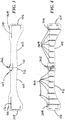
- the collapsible hanger 100 comprises a left arm 102 and a right arm 104 which are joined together by a hinge 202.
- the left arm 102 has a hinged end 110 and a distal end 106.
- the right arm 104 similarly has a hinged end 112 and a distal end 108.
- the hinge 202 is attached to both hinged ends 110, 112.
- a pin 710 in the hinge 202 holds the hinge 202 together.
- the pin 710 in the example, also provides indication of an axis of rotation for the arms 102, 104.
- a hook 107 is moveably coupled to the left arm 102.
- a hook 107 has a curved end 118 and a straight end 120.
- a pin hole near the end of the straight end 120 provides a mechanical joint that receives a locking pin 712 that secures the hook 107 to a mechanical joint at the hinged end of the left arm 102 in a rotational coupling arrangement.
- the locking pin 712 mates with a mating hole 714 in the straight end 120 of the hanger hook 107, and thereby secures the hanger hook 107 to a toothed wheel 902 that rotates along with rotation of the hook 107.
- a plastic end cap 716 mates with the other end of the locking pin 712, and provides a decorative cover on the locking pin 712.
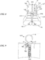
- the toothed wheel 902 rotates with its teeth being progressively rotationally engaged with notches along an outer circular structure 904 at least partially surrounding a portion of the toothed wheel 902, thereby providing a detent mechanism as shown in FIG. 9 .
- the straight end 120 of the hook 107, the toothed wheel 902, and the notched outer circular structure 904, are mechanically coupled together providing a detent mechanism that allows the hook 107 to gradually, progressively, rotate between at least two positions, and in certain embodiments several positions.
- the detent mechanism holds the hanger hook 107 in one or more of a plurality of positions around the rotatable coupling arrangement, until sufficient rotation force is applied to the hanger hook 107 to overcome the holding force of the detent at the particular position.
- the detent mechanism releases the hanger hook 107 from being held in one of a plurality of positions around the rotatable coupling arrangement by application of an external rotational force to the hanger hook 107 relative to the respective hinged end 110 of the left arm 102.
- a user of the collapsible hanger 100 can push using rotational force on the hanger hook 107 relative to the hinged end 110 such that the hanger hook 107 is released from the current position in the detent.
- the hanger hook 107 may then rotate to, and be held in, a next rotational position defined by the detent mechanism.
- the curved end 118 of the hook 107 is located above a top side of the hanger arms 102, 104.
- the curved end 118 of the hook 107 when in the first position (e.g., in an expanded state), can be used to hang the hanger 100 from another separate supporting structure (e.g., a hanger rod) in a known manner. See, for example, FIGs. 1, 2 , and 9 .
- the hanger arms 102, 104 can be rotated relative to each other between an expanded state and a collapsed state of the arms without impediment from the hook 107.
- the curved end 118 of the hook 107 is located below a top side of the hanger arms 102, 104.
- the curved end 118 of the hook 107 when in the second position (e.g., in a retracted state), can be rotated into a slot opening 802 and recess in the hanger 100.
- the curved end 118 of the hook 107 can be fully inserted into the slot opening 802 and recess in the hanger 100 as illustrated in the example of FIG. 8 . In this way, the hook 107 can be retracted into the slot opening 802 and held inside the recess in the hanger 100.
- the detent mechanism can hold the hook 107 secured in the recess in the hanger 100.
- Other mechanisms may be used to securely hold the hook 107 inside the recess.
- the hanger arms 102, 104 With the hook 107 out of the way inside the recess, the hanger arms 102, 104 can be rotated between the expanded state and the collapsed state without impediment from the hook 107.
- the hanger 100 arms 102, 104 can be in either an expanded state or a collapsed state independently of the hook 107 being in either an expanded state or a retracted state.
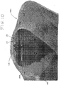
- FIG. 10 shows an example of a user's hand 1006 carrying a jacket 1001 on the hanger 100 with the hook 107 retracted into the slot opening 802 and recess in the hanger 100 and showing the hanger arms 102, 104 in an expanded state.
- the hinged ends 110, 112 are held together with magnetic attractive force between the plurality of magnets 702, 704, 706, 708, which are more clearly visible in FIG. 8 .
- the hanger's left arm 102 is inserted into the jacket 1001 supporting the left shoulder and arm 1002 of the jacket 1001.
- the hanger's right arm 104 is inserted into the jacket 1001 supporting the right shoulder and arm 1004 of the jacket 1001.
- the top side of the left arm 102 near its distal end 106 includes a raised rubber strip 114 that generally follows the outer perimeter of the distal end 106.
- the top side of the right hanger arm 104 near its distal end 108 includes a raised rubber strip 116 that generally follows the outer perimeter of the distal end 108.
- Each of the raised rubber strips 114, 116 has a set of tabs that mate into small slots in the top side of each of the left and right arms 102, 104.
- the raised rubber strips 114, 116 help prevent the material of the shoulders of a garment being held by the hanger 100 from migrating or slipping off the hanger arms 102, 104.
- the raised rubber strips 114, 116 help prevent the garment material from migrating or slipping from the hanger 100 in the various states of the hanger arms 102, 104.
- the garment material in an expanded state of the hanger arms 102, 104, such as shown in FIGs. 1 and 2 , the garment material can be prevented from slipping from the distal ends 106, 108 of the hanger arms 102, 104.
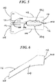
- the garment material in a collapsed state of the hanger arms 102, 104, such as shown in FIG. 5 , the garment material can be prevented from slipping from the gap 506.
- each of the left and right arms 102, 104 comprise a hollow recess region including a set of reinforcing bars 402, 404 inside the hollow recess region of each respective arm 102, 104.
- the reinforcing bars 402, 404 provide mechanical strength and at least some rigidity to the arms 102, 104 to help support garments on the hanger 100 with the hanger arms, in the expanded state, inserted into the sleeves of the garment.
- These reinforcing bars 402, 404 are only visible in the bottom-side view of the collapsible hanger 100 shown in FIG. 4 .
- the hanger 100 appears as a solid and sturdy high quality hanger 100, without readily showing the reinforcing bars 402, 404. It should be noted that while a number of the reinforcing bars 402, 404, are used in this example, other examples of the hanger 100 can be implemented with very few or with no reinforcing bars 402, 404
- the hanger arms 102, 104 are made of a high strength plastic or polymer material, for example polycarbonate. Texturing and coloring on the outer surfaces of the hanger arms 102, 104 can make the hanger 100 appear to be made of different types of materials.
- the hanger arms 102, 104 can be textured and colored such as to appear to be made from wood, carbon fiber, aluminum, etc.
- the hanger hook 107 could be made of a strong metal and could be colored such as to appear a precious metal or another high value metal, e.g., gold, silver, platinum, copper, brass, and the like.
- the rear side of the left arm 102 near its distal end 106 includes at least one magnet 204. While one magnet 204 is shown, a plurality of magnets can be located at the distal end 106. Similarly, the rear side of the right arm 104 near its distal end 108 includes at least one magnet 206. While one magnet 206 is shown, a plurality of magnets can be located at the distal end 108.
- the magnets 204, 206 can be colored or tinted to provide a higher quality finish to the hanger 100. The plurality of magnets 204, 206 at the distal ends 106, 108, when in proximity to each other magnetically attract each other.
- This arrangement of the collapsible hanger 100 is shown in FIG. 5 .
- the present example shows the hinge 202 being mechanically coupled with the hinged ends 110, 112 of the left and right arms 102, 104, proximal to a rear side of the first and second arms.
- the hinge 202 could be mechanically coupled with the hinged ends 110, 112 of the left and right arms 102, 104, proximal to the front side of the first and second arms 102, 104.
- the arms 102, 104 would rotate toward the front side to be rotated from an expanded state to a collapsed state.
- the collapsible hanger 100 can be in an expanded state, i.e., with both arms 102, 104 extended opposite each other in an expanded state and ready to be inserted into the sleeves of a hanging garment to support the hanging garment.
- This expanded state is shown, for example, in FIGs. 1 and 2 .
- the arms 102, 104 are held together in the expanded state by the hinge 202 and by a plurality of magnets 702, 704, 706, 708, located in the hinged ends 110, 112 of the arms 102, 104.
- FIG. 1 The arms 102, 104, are held together in the expanded state by the hinge 202 and by a plurality of magnets 702, 704, 706, 708, located in the hinged ends 110, 112 of the arms 102, 104.
- the hinge 202 is mechanically coupled with the hinged ends 110, 112 proximal the rear side of the arms 102, 104, and there are at least two magnets 702, 704 located in the hinged end 110 of the left arm 102 proximal the front side of the arm 102, and at least two magnets 706, 708 located in the hinged end 112 of the right arm 104 proximal the front side of the arm 104.
- the arms 102, 104 would rotate toward the rear side to be rotated from an expanded state to a collapsed state. While four magnets are shown in the current example, various embodiments of the present disclosure may include two or more magnets paired together with at least one magnet located at each of the hinged ends 110, 112.
- the two magnets 702, 706 near the top side of the arms 102, 104 are paired together and magnetically attractive with each other.
- the two magnets 704, 708 near the bottom side of the arms 102, 104 are paired together and magnetically attractive with each other.
- the hinge 202 could be coupled with the hinged ends 110, 112, proximal to the front side of the arms 102, 104.
- at least one magnet would be located at each of the hinged ends 110, 112, proximal to the rear side of the arms 102, 104.
- the arms 102, 104 would rotate toward the front side from an extended state to a collapsed state.
- the collapsible hanger 100 can be in a collapsed state, i.e., with both arms 102, 104 rotated from the expanded state to the collapsed state using the hinge 202.
- the lengths of the arms 102, 104 i.e., extending from the hinged ends 110, 112 to the distal ends 106, 108) are generally adjacent to each other as illustrated in FIG. 5 .
- the two magnets 204, 206 are paired together in proximity to each other in the collapsed state.
- the collapsed arms 102, 104 are secured together by the attractive magnetic force between the plurality of magnets 204, 206 near the distal ends 106, 108 of the arms 102, 104.
- the attractive magnetic force between the magnets 204, 206 in proximity with each other in the collapsed state is strong enough to hold together the distal ends 106, 108 of the arms 102, 104 through garment material from a garment such as a shirt or a suit located between the magnets 204, 206 and being held by the arms 102, 104.
- FIGs. 11 and 12 An example of this arrangement of the collapsible hanger 100 is shown in FIGs. 11 and 12 .
- a jacket 1001 is held by the sleeve arms 102, 104 when the collapsible hanger 100, while inserted into the sleeve arms of the jacket 1001, is rotated by a user 1104 from the expanded state to the collapsed state of the hanger 100.
- the jacket 1001 is folded toward its rear side while mounted on the hanger 100 and held in this position by the hanger arms 102, 104 in the collapsed state.
- the magnets 204, 206 in proximity to each other while the hanger 100 is in the collapsed state, attract each other with magnetic force passing through the material of the jacket 1001.
- the collapsed arms 102, 104 are secured together, and hold the jacket 1001 in a folded state near its shoulder region, by the attractive magnetic force between the magnets 204, 206 near the distal ends 106, 108 of the arms 102, 104.
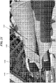
- FIG. 11 shows the hanger hook 107 rotated to a position where the curved end 118 of the hanger hook 107 is rotated to a fully expanded state.
- FIG. 12 shows the hanger hook 107 rotated to a position where the curved end 118 of the hanger hook 107 is located below a top side of the respective hinged end of the hanger arm.
- FIG. 13 shows the hanger hook 107 rotated to a position where the curved end 118 of the hanger hook 107 is rotated into a slot opening and recess in the respective hinged end of the hanger arm.
- the gap 506 is formed by inwardly curved surface areas 502, 504 at the rear side of the respective arms 102, 104.
- the gap 506 maintaining separation between the inwardly curved surface areas 502, 504 of the collapsed arms 102, 104 helps the fold 1106 of the garment, especially around the collar region of the garment, to remain loose, wrinkle-fee, and crease-free while the garment is held by the collapsed hanger arms 102, 104.
- the gap formed provides at least approximately half an inch of separation between the inwardly curved surface areas of the arms.
- the folded garment, with the hanger arms in the collapsed state can be conveniently stored in at least one of a brief case, suit case, personal carrying bag, storage container, and drawer.
- Various alternative embodiments can form a gap between the inwardly curved surface areas of the arms to provide different separation distances, which may be greater than or less than the half an inch of separation according to the present example.
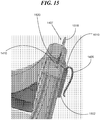
- FIGs. 14 to 18 illustrate an alternative example of the collapsible hanger 100, 1400, according to various embodiments of the present disclosure.
- FIG. 14 shows a top view of the alternative example collapsible hanger 1400. It generally corresponds to the collapsible hanger 100 that was discussed above. Arrow 1409 indicates the front side of the collapsible hanger 1400. Arrow 1411 indicates the rear side of the collapsible hanger 1400.
- the left hanger arm 1402 is rotatably coupled at its hinged end 1410 with the hinged end 1412 of the right hanger arm 1404. In this alternative example, the pin 710 in the hinge 202 of the collapsible hanger 100 (see FIGs.
- the clasp 1406 can comprise a curved portion of the pin 1510 overhanging, in close proximity to, the outer surface of the hinge 1502 to form the clasp therewith.
- the clasp (not shown) could be formed as a clasp structure separate from, but in close proximity to, the hinge 1502.
- the clasp 1406 can additionally securely hold the collar of the garment to the hinged ends of the hanger arms 1402, 1404.
- the separate clasp structure could operate as a clasp separate from the outer surfaces of the hinge 1502 to securely hold the collar of the garment to the hinged ends 1410, 1412, of the hanger arms 1402, 1404, of the collapsible hanger 1400. While the clasp is discussed in the example above as holding the collar of the garment, it should be understood that the clasp can be used to hold other portion of the garment.
- the purpose of the clasp is to immobilize the garment relative to the hanger hinged ends 1410, 1412, of the hanger arms 1402, 1404, of the collapsible hanger 1400. In this way, the possibility of wrinkling this region of the garment while collapsing the hanger 1400 is significantly reduced or entirely eliminated.
- the clasp 1406, is mechanically coupled with the hinge pin 1510 such that it can function both as a hinge pin 1510 (interoperating with the inside surfaces of the rotating hinge 1502 to hold the hinge together) and as well as a clasp 1406 (interoperating with the outside surfaces of the hinge 1502) that is particularly relevant to the collapsible hanger 100, 1400, as it closes.
- a hinge pin 1510 interoperating with the inside surfaces of the rotating hinge 1502 to hold the hinge together
- a clasp 1406 interoperating with the outside surfaces of the hinge 1502 that is particularly relevant to the collapsible hanger 100, 1400, as it closes.
- the straight end 1520 of the hanger hook 1407 is mechanically coupled with one of a ball or a socket, and the left hanger arm 1402 being mechanically coupled with the other one of the ball or socket in a ball and socket arrangement at the hinged end 1410 of the left hanger arm 1402.
- This allows the collapsible hanger 1400 while in the expanded state to hang from the curved end 1518 of the hanger 1407 mounted on another separate supporting structure (e.g., a hanger rod) in a known manner.
- the expanded collapsible hanger 1400 using the ball and socket mechanism can have its hanger arms 1402, 1404, horizontally rotated by up to three hundred and sixty degrees (360 degrees) or more of rotation about a vertical axis running through the straight end 1520 of the hanger hook 1407.
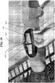
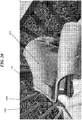
- a collar portion 1902 of a garment e.g., a jacket
- the clasp 1406 securely holds a fold 1106 on the collar portion 1902 of the garment 1001.
- This clasp feature 1406 effectively secures the collar 1902 of the garment 1001 to the hanger 1400 and prevents migration of the collar portion 1902 of the garment 1001 that is sandwiched between the two collapsing hanger arms 1402, 1404, (i.e., that are moving in a rotating motion toward each other) avoiding misalignment of the shoulders of the garment and potential wrinkling thereof. In this way, the possibility of wrinkling this region 1902 of the garment 1001 while collapsing the hanger 1400 is significantly reduced or entirely eliminated.
- a socket 1604 is formed on the underside of the hinged end 1410 of the left hanger arm 1402 in a recess region near the slot opening 1602 of the hinged end 1410.
- the socket 1604 includes a slotted region 1606 that is generally aligned with the slot opening 1602 of the hinged end 1410 of the left hanger arm 1402.
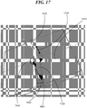
- the straight end 1520 of the hanger hook 1407 is mechanically coupled with the ball 1702.
- the ball 1702 is affixed to the very end of the straight end 1520 of the hanger hook 1407.
- the diameter of the ball 1702 is sized slightly larger than the diameter of an inside recess region of the socket 1604 that receives the ball 1702. This creates friction tension between the surface of the ball 1702 and the surface of the inside recess region of the socket 1604.
- the ball 1702 does not freely move in the socket 1604.
- the ball 702 can be moved by external force (e.g., provided by a user on the collapsible hanger) overcoming the shear friction of these surfaces caused by the tension in the socket 1604. In this way, by overcoming the shear friction force of the ball and socket arrangement, the user can force relative movement between the hook 1407 and the rest of the hanger 1400.
- This ball 1702 and socket 1604 system is used to retain the retracting hook 1407 mechanism.
- the hook 1407 and ball 1702 portion is installed in the socket 1604 through the bottom aperture of the hanger 1400 and pops securely in place after molding.
- the hook 1407 can then be rotated from the underside of the hinged end 1410 of the left hanger arm 1402, through the slot opening 1602 of the hinged end 1410, and upward into an expanded hanger hook 1407 position such as shown in FIGs. 14 and 15 .
- the socket 1604 includes a slotted region 1606 that is generally aligned with the slot opening 1602 of the hinged end 1410 of the left hanger arm 1402.
- the ball 1702 can include a slot feature 1802 as shown in FIG. 18 .
- This allows an external instrument e.g., a fat head screw driver
- This slot feature 1802 can be useful to adjust the position of the ball 1702 in the socket 1604.
- the terms “a” or “an”, as used herein, are defined as one or more than one.
- the term “plurality”, as used herein, is defined as two or more than two.
- the term “another”, as used herein, is defined as at least a second or more.
- the terms “including” and “having,” as used herein, are defined as comprising (i.e., open language).
- the term “coupled,” as used herein, is defined as “connected,” although not necessarily directly, and not necessarily mechanically.
- the term “configured to” describes structure that is adapted to, set up, arranged, commanded, altered, modified, built, composed, constructed, designed, or that has any combination of these characteristics to carry out a given function.
- the term “adapted to” describes structure that is capable of, able to accommodate, to make, or that is suitable to carry out a given function.
Landscapes
- Holders For Apparel And Elements Relating To Apparel (AREA)
Claims (15)
- Ein klappbarer Kleiderbügel (100, 1400), bestehend aus:Arm 1(102, 1402) und Arm 2 (104, 1404), wobei jeder Arm über ein Scharnier-Ende(1 10, 112, 1410, 1412) und ein distales Ende (106, 108) verfügt. Die Rückseite jedes Arms ist vom Scharnier-Ende über die Länge des jeweiligen Arms in Richtung des distalen Endes ausgespart, wobei die Länge der ausgesparten Fläche kürzer ist als die Gesamtlänge des Arms;einem Scharnier (202), das mit den jeweiligen Scharnier-Enden von Arm 1 und Arm 2 verbunden ist. Arm 1 und Arm 2können mithilfe des Scharniers aufeinander zu bzw. voneinander wegbewegt werden, und zwar zwischeneiner aufgeklappten Position, bei derArm 1 und Arm 2jeweils in die entgegengesetzte Richtung aufgeklappt werden, sodass die jeweiligen Scharnier-Enden und entsprechenden distalen Enden der Arme auf einer Ebene liegen, undeiner zusammengeklappten Position, bei der die jeweiligen distalen Enden von Arm 1 und Arm 2 von den Scharnier-Enden ausgehend entlang ihrer Rückseiten aneinander geklappt werden;einem Haken (107)mit einem gebogenen Ende (118)und einem geraden Ende (120, 1520), einer Gelenkkomponente 1 am oder nahe des geraden Endes, die drehbar an einem Kugelgelenk befestigt ist und einer Gelenkkomponente 2, die am oder nahe des Scharnier-Endes (110, 112, 1410, 1412) von Arm 1 oder Arm 2 angebracht ist. Durch das Zusammenspiel aus Gelenkkomponente 1 und 2 kann der Haken, sofern sich Arm 1 und 2 in der zusammengeklappten Position befinden, in zwei verschiedene Positionen gebracht werden, nämlichPosition 1: das gebogene Ende des Hakens befindet sich auf der und senkrecht zur Oberseite des Scharnier-Endes des jeweiligen Arms, undPosition 2: das gebogene Ende des Hakens befindet sich unter der Oberseite des Scharnier-Endes des jeweiligen Arms, undeiner der Arme verfügt am Scharnier-Ende über eine Vertiefung hat, die zum gebogenen Ende des Hakens passt, sofern dieser sich auf Position 2 befindet.
- Laut Anforderung 1 ist der Haken durch das Kugelgelenk (1702, 1604) in seiner Position verstellbar.
- Laut Anforderung 1 kann der Haken im Verhältnis zu den Armen des klappbaren Kleiderbügels um 360 Grad oder mehr gedreht und dank eines Kugelgelenks in der Position verstellt werden.
- Laut Anforderung 1 ist der Haken im Verhältnis zu Arm 1 und 2 des klappbaren Kleiderbügels um 360 Grad oder mehr drehbar, sofern sich die Arme in der aufgeklappten Position befindeen. Durch das Kugelgelenk bestehend aus einer Kugel und einer Pfanne, deren Oberflächen formschlüssig miteinander verbunden sind, kann die Position des Hakens verändert werden. Die Scherspannung zwischen den Oberflächen, die den Haken in Position hält, kann nur durch extern angelegte Kraft überwunden werden.
- Laut Anforderung 4 hält die Scherspannung zwischen den Oberflächen des Kugelgelenks das gebogene Ende des Hakens in der Vertiefung des Scharnier-Endes von Arm 1 oder 2, sofern sich der Haken auf Position 2 befindet.
- Laut Anforderung 1 verfügt das Kugelgelenk über eine Pfanne (1604) in der Vertiefung am Scharnier-Ende des betreffenden Arms.
- Laut Anforderung 6 handelt es sich bei der Vertiefung am Scharnier-Ende des jeweiligen Arms um eine schlitzförmige Vertiefung und verfügt die Gelenkpfanne (1604) ebenfalls über einen Schlitz (1606), dessen Maße an die der schlitzförmigen Vertiefung (1602) am Scharnier-Ende des jeweiligen Arms angepasst sind.
- Laut Anforderung 6 ist die Kugel des Kugelgelenks am geraden Ende des Hakens befestigt.
- Laut Anforderung 1 verfügt das Scharnier über einen Stift (1510), der das Scharnier in Position hält, der mit einer Klammer (1406) in der Nähe des Scharniers verbunden ist. Diese Klammer befestigt Kleidungsstücke sicher an den Scharnier-Enden der Arme des klappbaren Kleiderbügels.
- Laut Anforderung 9 verfügt der klappbare Kleiderbügel über eine Klammer, die den Kragen des Kleidungsstücks sicher an den Scharnier-Enden der Arme des klappbaren Kleiderbügels fixiert.
- Laut Anforderung 9 ist die Klammer an einem überstehenden, gebogenen Fortsatz des Stifts in der Nähe der Außenfläche des Scharniers angebracht.
- Laut Anforderung 9 ist die Klammer am Stift befestigt, und zwar in der Nähe Scharniers, von dem sie aber kein Bestandteil ist.
- Laut Anforderung 1 verfügt der klappbare Kleiderbügel über einen ersten, mindestens einen Magneten (702, 704) am Scharnier-Ende von Arm 1 und einen zweiten, mindestens einen Magneten (706, 708) am Scharnier-Ende von Arm 2. In der ausgeklappten Position des Kleiderbügels befindet sich der erste mindestens eine Magnet in der Nähe des zweiten mindestens einen Magneten und Arm 1 und Arm 2 werden durch die Anziehungskraft der Magnete in der ausgeklappten Position gehalten. Der erste, mindestens eine Magnet am Scharnier-Ende von Arm 1 zieht den zweiten, mindestens einen Magneten am Scharnier-Ende von Arm 2 an.
- Laut Anforderung 1 kann der Haken von Position 1 in Position 2 gebracht werden, in der das gebogene Ende des Hakens in die Vertiefung des jeweiligen Scharnier-Endes von entweder Arm 1 oder Arm 2 eingeführt wird, sofern sich Arm 1 und 2 in der zusammengeklappten Position befinden.
- Anwendungsbeispiel eines klappbaren Kleiderbügels, bestehend aus:Arm 1 (102, 1402) und Arm 2 (104, 1404), wobei jeder Arm über ein Scharnier-Ende (110, 112, 1410, 1412) und ein distales Ende (106, 108) verfügt. Die Rückseite jedes Arms ist vom Scharnier-Ende über die Länge des jeweiligen Arms in Richtung des distalen Endes bis etwa zur Mitte des jeweiligen Arms ausgespart;den jeweiligen Scharnier-Enden (110, 112, 1410, 1412) von Arm 1 und Arm 2, die mithilfe eines Scharniers aufeinander zu bzw. voneinander wegbewegt werden, und zwar zwischeneiner aufgeklappten Position, bei der Arm 1 und Arm 2 jeweils in die entgegengesetzte Richtung aufgeklappt werden, sodass die jeweiligen Scharnier-Enden und entsprechenden distalen Enden der Arme auf einer Ebene liegen, undeiner zusammengeklappten Position, bei der die jeweiligen distalen Enden von Arm 1 und Arm 2 von den Scharnier-Enden ausgehend entlang ihrer Rückseiten aneinander geklappt werden;einem Haken, bestehend aus einem gebogenen und einem geraden Ende. Das gerade Ende ist über ein Gelenk mit dem Scharnier-Ende von entweder Arm 1 oder Arm 2 verbunden, wodurch der Haken zwischen Position 1 und Position 2 verstellt werden kann, sofern sich Arm 1 und Arm 2 in der zusammengeklappten Position befinden, nämlichPosition 1: das gebogene Ende des Hakens befindet sich auf der und senkrecht zur Oberseite des Scharnier-Endes des jeweiligen Arms, undPosition 2: das gebogene Ende des Hakens befindet sich unter der Oberseite des Scharnier-Endes des jeweiligen Arms, und
einer der Arme verfügt am Scharnier-Ende über eine Vertiefung hat, die zum gebogenen Ende des Hakens passt, sofern dieser sich auf Position 2 befindet; und der Anwendung wie folgt:Durch die Anlegung externer Kraft auf den Haken kann dieser in Position 2 bewegt werden, in der das gebogene Ende des Hakens in die Vertiefung eingeführt wird.
Applications Claiming Priority (3)
| Application Number | Priority Date | Filing Date | Title |
|---|---|---|---|
| US14/853,448 US9687099B2 (en) | 2015-09-14 | 2015-09-14 | Collapsible hanger for use in-garment to reduce creasing, crushing, and wrinkling, while maintaining support, of upper garment during storage and transportation |
| US15/209,009 US9801485B2 (en) | 2015-09-14 | 2016-07-13 | Collapsible hanger for use in-garment to reduce creasing, crushing, and wrinkling, while maintaining support and structure, of upper garment during storage and transportation |
| PCT/US2016/051680 WO2017048806A1 (en) | 2015-09-14 | 2016-09-14 | Collapsible hanger to reduce creasing |
Publications (3)
| Publication Number | Publication Date |
|---|---|
| EP3349619A1 EP3349619A1 (de) | 2018-07-25 |
| EP3349619A4 EP3349619A4 (de) | 2019-08-21 |
| EP3349619B1 true EP3349619B1 (de) | 2021-08-04 |
Family
ID=58256878
Family Applications (1)
| Application Number | Title | Priority Date | Filing Date |
|---|---|---|---|
| EP16847207.4A Active EP3349619B1 (de) | 2015-09-14 | 2016-09-14 | Zusammenklappbarer bügel zur verringerung der faltenbildung |
Country Status (4)
| Country | Link |
|---|---|
| US (1) | US9801485B2 (de) |
| EP (1) | EP3349619B1 (de) |
| ES (1) | ES2895924T3 (de) |
| WO (1) | WO2017048806A1 (de) |
Families Citing this family (8)
| Publication number | Priority date | Publication date | Assignee | Title |
|---|---|---|---|---|
| GB201408151D0 (en) * | 2014-05-08 | 2014-06-25 | Firstlight Projects London Ltd | Carrier apparatus for garments |
| EP3192405A1 (de) * | 2016-01-18 | 2017-07-19 | Salvatore Milazzo | Kleiderbügel mit magnete |
| EP3634182B1 (de) * | 2017-06-09 | 2023-11-15 | Davidoff, Jessica | Kompakter kleiderbügel |
| US20190150646A1 (en) * | 2017-11-21 | 2019-05-23 | Gnanavathanan Raphael Maharajah | Folding clothes hanger |
| US11478097B2 (en) * | 2018-09-07 | 2022-10-25 | Brian Curci | Collapsible hanger cover |
| EP3965621A2 (de) * | 2019-05-15 | 2022-03-16 | Anton, George-Adrian | Doppelgelenkige vorrichtung und system |
| USD896533S1 (en) * | 2019-07-05 | 2020-09-22 | Neu-Ventures, Inc. | Multi-hinged foldable hanger |
| US20220369839A1 (en) * | 2021-05-18 | 2022-11-24 | DeAnne Murray | Foldable Garment Hanger |
Family Cites Families (37)
| Publication number | Priority date | Publication date | Assignee | Title |
|---|---|---|---|---|
| US881818A (en) * | 1907-02-11 | 1908-03-10 | John Morrison Jr | Combined wardrobe appliance. |
| US863236A (en) * | 1907-03-25 | 1907-08-13 | John P Sundin | Garment-hander. |
| US1059649A (en) * | 1912-05-06 | 1913-04-22 | James Wallace | Coat-hanger. |
| FR629628A (fr) * | 1927-02-21 | 1927-11-14 | Pierre M Rosier | Perfectionnement aux porte-manteaux et autres supports de vêtements |
| US1836942A (en) * | 1928-09-08 | 1931-12-15 | Sumi Yuji | Combined coat hanger and hat brush |
| US1836935A (en) * | 1931-04-28 | 1931-12-15 | Fold Brush Mfg Co Inc Du | Foldable wardrobe appliance |
| US2425527A (en) * | 1945-07-24 | 1947-08-12 | Gaudino Orlando Alboeno | Disappearing hanger hook |
| US2544170A (en) * | 1946-04-30 | 1951-03-06 | Fred M Mills | Folding garment hanger |
| US2478590A (en) * | 1946-06-24 | 1949-08-09 | Lola F Mcknelly | Folding coat hanger |
| US4168791A (en) * | 1978-03-24 | 1979-09-25 | Tantera, Inc. | Folding hanger |
| US4300688A (en) * | 1980-04-16 | 1981-11-17 | Wallace London | Compact merchandising package of a flexible garment bag and collapsible hanger |
| US4624396A (en) * | 1985-10-28 | 1986-11-25 | Universe Samy F | Garment hanger |
| US4669642A (en) * | 1986-02-10 | 1987-06-02 | Nicholas Robert J L | Foldable shirt hanger with reinforced collar |
| IT211356Z2 (it) * | 1987-03-06 | 1989-03-06 | Mazzei Mfg Srl | Appendiabito in plastica o simile con gancio snodato a due gradi di liberta'. |
| US5085357A (en) * | 1991-04-17 | 1992-02-04 | Chen Ken Wang | Collapsible garment hanger with hook recess |
| US5154329A (en) * | 1991-11-12 | 1992-10-13 | Dorfmueller Daniel P | Configured shirt-shaper article for folding shirts |
| US5566843A (en) * | 1994-03-01 | 1996-10-22 | Kruska; Phillip C. | Retractable folding hanger device |
| US5749505A (en) * | 1995-01-30 | 1998-05-12 | Reyes; Daniel | Autofoldable garment hanger for motor vehicle |
| US5480076A (en) * | 1995-03-27 | 1996-01-02 | Siegel; Kenneth D. | Clothes hanger with retractable arms |
| US5687888A (en) * | 1996-08-29 | 1997-11-18 | Chang; Ching-Chao | Multifunctional foldable hanger |
| IL119517A0 (en) | 1996-10-30 | 1997-01-10 | Hecht Michael | Foldable shirt hanger |
| US5813578A (en) * | 1996-12-24 | 1998-09-29 | Hsieh; Sing-Fuh | Foldable suit hanger |
| HK1005636A2 (en) | 1997-04-17 | 1998-12-18 | Samsonite Corporation | Folding hanger system for luggage |
| US5893493A (en) * | 1998-02-26 | 1999-04-13 | Noiray; Jean-Luc G. | Foldable clothes hanger |
| JP3557375B2 (ja) * | 1998-12-18 | 2004-08-25 | 株式会社タヤ | 衣料用ハンガー |
| KR200175314Y1 (ko) | 1999-09-22 | 2000-03-15 | 정홍준 | 옷걸이 |
| US6296160B1 (en) * | 2000-08-04 | 2001-10-02 | James Murray | Clothes hanger |
| CN2555736Y (zh) * | 2002-07-04 | 2003-06-18 | 叶仲伦 | 新型便携式折叠衣架 |
| US7237702B2 (en) * | 2003-04-22 | 2007-07-03 | Gary Landis | Folding garment hanger |
| USD508614S1 (en) * | 2004-02-24 | 2005-08-23 | Hector M. Colon | Foldable clothes hanger |
| US7243823B2 (en) * | 2004-11-10 | 2007-07-17 | Zadee Industries, Llc | Collapsible garment hanger with quick-release lever |
| GB2422536A (en) * | 2005-01-26 | 2006-08-02 | Hoi Yi Wong | Collapsible garment hanger |
| US7185795B1 (en) * | 2005-10-25 | 2007-03-06 | Wallick James R | Collapsible hanger for suspending clothes and other items |
| US7837074B2 (en) * | 2007-04-17 | 2010-11-23 | Rude Richard R | Garment hanger with a collapsible/retractable support hook |
| US7784654B1 (en) * | 2008-03-07 | 2010-08-31 | Geraldo Mercado | Collapsible travel hanger |
| US8113393B2 (en) * | 2008-04-07 | 2012-02-14 | The Build-Up Plastic & Metal Co., Ltd. | Collapsible hook hanger |
| US8459514B2 (en) * | 2010-04-26 | 2013-06-11 | Bruce Lagzdins | Collapsible adjustable garment hanging device |
-
2016
- 2016-07-13 US US15/209,009 patent/US9801485B2/en active Active
- 2016-09-14 ES ES16847207T patent/ES2895924T3/es active Active
- 2016-09-14 EP EP16847207.4A patent/EP3349619B1/de active Active
- 2016-09-14 WO PCT/US2016/051680 patent/WO2017048806A1/en not_active Ceased
Non-Patent Citations (1)
| Title |
|---|
| None * |
Also Published As
| Publication number | Publication date |
|---|---|
| EP3349619A1 (de) | 2018-07-25 |
| WO2017048806A1 (en) | 2017-03-23 |
| EP3349619A4 (de) | 2019-08-21 |
| US20170071386A1 (en) | 2017-03-16 |
| ES2895924T3 (es) | 2022-02-23 |
| US9801485B2 (en) | 2017-10-31 |
Similar Documents
| Publication | Publication Date | Title |
|---|---|---|
| EP3349619B1 (de) | Zusammenklappbarer bügel zur verringerung der faltenbildung | |
| US8523026B2 (en) | Garment hanger | |
| US8459514B2 (en) | Collapsible adjustable garment hanging device | |
| US9687099B2 (en) | Collapsible hanger for use in-garment to reduce creasing, crushing, and wrinkling, while maintaining support, of upper garment during storage and transportation | |
| US9468326B2 (en) | Collapsible hanger apparatus and methods of use thereof | |
| US4997115A (en) | Foldable garment hanger | |
| CN108495572A (zh) | 具有作为衣架的可折叠延伸件的行李箱手柄 | |
| US20200154921A1 (en) | Clothes hanger having extension rods | |
| US6293443B1 (en) | Foldable garment hanger for compactly storing garments when traveling | |
| KR20180136173A (ko) | 접이식 옷걸이 | |
| US8881350B2 (en) | Clip for folded fabrics | |
| JP4116090B2 (ja) | かばん用折りたたみ式ハンガー装置 | |
| JP2014104072A (ja) | 和服用ハンガー | |
| KR101477564B1 (ko) | 가방에 일체로 형성된 우산 | |
| US6053379A (en) | Garment hanger sleeve extension | |
| US980219A (en) | Garment-hanger. | |
| US20190380411A1 (en) | Adjusting strap for adjusting tube orifice diameter of flexible tube-shaped object | |
| CN113874576A (zh) | 用于支撑衣服的支撑装置 | |
| KR102787300B1 (ko) | 주름 방지용 옷걸이 | |
| US11959212B2 (en) | Alignment device for sewing alignment | |
| KR200340582Y1 (ko) | 바지걸이 겸용 옷걸이 | |
| US20220022677A1 (en) | Expandable clothing hanger | |
| KR100650177B1 (ko) | 파라솔의 그늘막 개폐구조 | |
| JP2005124887A (ja) | 折畳式ハンガー | |
| KR910001094Y1 (ko) | 휴대용 절첩식 파라솔 |
Legal Events
| Date | Code | Title | Description |
|---|---|---|---|
| STAA | Information on the status of an ep patent application or granted ep patent |
Free format text: STATUS: THE INTERNATIONAL PUBLICATION HAS BEEN MADE |
|
| PUAI | Public reference made under article 153(3) epc to a published international application that has entered the european phase |
Free format text: ORIGINAL CODE: 0009012 |
|
| STAA | Information on the status of an ep patent application or granted ep patent |
Free format text: STATUS: REQUEST FOR EXAMINATION WAS MADE |
|
| 17P | Request for examination filed |
Effective date: 20180416 |
|
| AK | Designated contracting states |
Kind code of ref document: A1 Designated state(s): AL AT BE BG CH CY CZ DE DK EE ES FI FR GB GR HR HU IE IS IT LI LT LU LV MC MK MT NL NO PL PT RO RS SE SI SK SM TR |
|
| AX | Request for extension of the european patent |
Extension state: BA ME |
|
| RAP1 | Party data changed (applicant data changed or rights of an application transferred) |
Owner name: SNOW, BRAD ALAN |
|
| RIN1 | Information on inventor provided before grant (corrected) |
Inventor name: SNOW, BRAD ALAN |
|
| DAV | Request for validation of the european patent (deleted) | ||
| DAX | Request for extension of the european patent (deleted) | ||
| A4 | Supplementary search report drawn up and despatched |
Effective date: 20190722 |
|
| RIC1 | Information provided on ipc code assigned before grant |
Ipc: A47G 25/14 20060101ALI20190716BHEP Ipc: A47G 25/32 20060101ALI20190716BHEP Ipc: A47G 25/40 20060101ALI20190716BHEP Ipc: A47G 25/02 20060101AFI20190716BHEP Ipc: A47G 25/30 20060101ALI20190716BHEP |
|
| RIC1 | Information provided on ipc code assigned before grant |
Ipc: A47G 25/32 20060101ALI20200612BHEP Ipc: A47G 25/14 20060101ALI20200612BHEP Ipc: A47G 25/40 20060101ALI20200612BHEP Ipc: A47G 25/02 20060101AFI20200612BHEP Ipc: A47G 25/30 20060101ALI20200612BHEP |
|
| GRAP | Despatch of communication of intention to grant a patent |
Free format text: ORIGINAL CODE: EPIDOSNIGR1 |
|
| STAA | Information on the status of an ep patent application or granted ep patent |
Free format text: STATUS: GRANT OF PATENT IS INTENDED |
|
| INTG | Intention to grant announced |
Effective date: 20200727 |
|
| GRAS | Grant fee paid |
Free format text: ORIGINAL CODE: EPIDOSNIGR3 |
|
| GRAJ | Information related to disapproval of communication of intention to grant by the applicant or resumption of examination proceedings by the epo deleted |
Free format text: ORIGINAL CODE: EPIDOSDIGR1 |
|
| GRAL | Information related to payment of fee for publishing/printing deleted |
Free format text: ORIGINAL CODE: EPIDOSDIGR3 |
|
| STAA | Information on the status of an ep patent application or granted ep patent |
Free format text: STATUS: REQUEST FOR EXAMINATION WAS MADE |
|
| INTC | Intention to grant announced (deleted) | ||
| GRAP | Despatch of communication of intention to grant a patent |
Free format text: ORIGINAL CODE: EPIDOSNIGR1 |
|
| STAA | Information on the status of an ep patent application or granted ep patent |
Free format text: STATUS: GRANT OF PATENT IS INTENDED |
|
| INTG | Intention to grant announced |
Effective date: 20210326 |
|
| GRAA | (expected) grant |
Free format text: ORIGINAL CODE: 0009210 |
|
| STAA | Information on the status of an ep patent application or granted ep patent |
Free format text: STATUS: THE PATENT HAS BEEN GRANTED |
|
| AK | Designated contracting states |
Kind code of ref document: B1 Designated state(s): AL AT BE BG CH CY CZ DE DK EE ES FI FR GB GR HR HU IE IS IT LI LT LU LV MC MK MT NL NO PL PT RO RS SE SI SK SM TR |
|
| REG | Reference to a national code |
Ref country code: GB Ref legal event code: FG4D |
|
| REG | Reference to a national code |
Ref country code: AT Ref legal event code: REF Ref document number: 1416085 Country of ref document: AT Kind code of ref document: T Effective date: 20210815 |
|
| REG | Reference to a national code |
Ref country code: CH Ref legal event code: EP |
|
| REG | Reference to a national code |
Ref country code: DE Ref legal event code: R096 Ref document number: 602016061753 Country of ref document: DE |
|
| REG | Reference to a national code |
Ref country code: IE Ref legal event code: FG4D |
|
| REG | Reference to a national code |
Ref country code: LT Ref legal event code: MG9D |
|
| REG | Reference to a national code |
Ref country code: NL Ref legal event code: MP Effective date: 20210804 |
|
| REG | Reference to a national code |
Ref country code: AT Ref legal event code: MK05 Ref document number: 1416085 Country of ref document: AT Kind code of ref document: T Effective date: 20210804 |
|
| PG25 | Lapsed in a contracting state [announced via postgrant information from national office to epo] |
Ref country code: SE Free format text: LAPSE BECAUSE OF FAILURE TO SUBMIT A TRANSLATION OF THE DESCRIPTION OR TO PAY THE FEE WITHIN THE PRESCRIBED TIME-LIMIT Effective date: 20210804 Ref country code: RS Free format text: LAPSE BECAUSE OF FAILURE TO SUBMIT A TRANSLATION OF THE DESCRIPTION OR TO PAY THE FEE WITHIN THE PRESCRIBED TIME-LIMIT Effective date: 20210804 Ref country code: LT Free format text: LAPSE BECAUSE OF FAILURE TO SUBMIT A TRANSLATION OF THE DESCRIPTION OR TO PAY THE FEE WITHIN THE PRESCRIBED TIME-LIMIT Effective date: 20210804 Ref country code: AT Free format text: LAPSE BECAUSE OF FAILURE TO SUBMIT A TRANSLATION OF THE DESCRIPTION OR TO PAY THE FEE WITHIN THE PRESCRIBED TIME-LIMIT Effective date: 20210804 Ref country code: BG Free format text: LAPSE BECAUSE OF FAILURE TO SUBMIT A TRANSLATION OF THE DESCRIPTION OR TO PAY THE FEE WITHIN THE PRESCRIBED TIME-LIMIT Effective date: 20211104 Ref country code: FI Free format text: LAPSE BECAUSE OF FAILURE TO SUBMIT A TRANSLATION OF THE DESCRIPTION OR TO PAY THE FEE WITHIN THE PRESCRIBED TIME-LIMIT Effective date: 20210804 Ref country code: HR Free format text: LAPSE BECAUSE OF FAILURE TO SUBMIT A TRANSLATION OF THE DESCRIPTION OR TO PAY THE FEE WITHIN THE PRESCRIBED TIME-LIMIT Effective date: 20210804 Ref country code: NO Free format text: LAPSE BECAUSE OF FAILURE TO SUBMIT A TRANSLATION OF THE DESCRIPTION OR TO PAY THE FEE WITHIN THE PRESCRIBED TIME-LIMIT Effective date: 20211104 Ref country code: PT Free format text: LAPSE BECAUSE OF FAILURE TO SUBMIT A TRANSLATION OF THE DESCRIPTION OR TO PAY THE FEE WITHIN THE PRESCRIBED TIME-LIMIT Effective date: 20211206 |
|
| REG | Reference to a national code |
Ref country code: ES Ref legal event code: FG2A Ref document number: 2895924 Country of ref document: ES Kind code of ref document: T3 Effective date: 20220223 |
|
| PG25 | Lapsed in a contracting state [announced via postgrant information from national office to epo] |
Ref country code: PL Free format text: LAPSE BECAUSE OF FAILURE TO SUBMIT A TRANSLATION OF THE DESCRIPTION OR TO PAY THE FEE WITHIN THE PRESCRIBED TIME-LIMIT Effective date: 20210804 Ref country code: LV Free format text: LAPSE BECAUSE OF FAILURE TO SUBMIT A TRANSLATION OF THE DESCRIPTION OR TO PAY THE FEE WITHIN THE PRESCRIBED TIME-LIMIT Effective date: 20210804 Ref country code: GR Free format text: LAPSE BECAUSE OF FAILURE TO SUBMIT A TRANSLATION OF THE DESCRIPTION OR TO PAY THE FEE WITHIN THE PRESCRIBED TIME-LIMIT Effective date: 20211105 |
|
| PG25 | Lapsed in a contracting state [announced via postgrant information from national office to epo] |
Ref country code: NL Free format text: LAPSE BECAUSE OF FAILURE TO SUBMIT A TRANSLATION OF THE DESCRIPTION OR TO PAY THE FEE WITHIN THE PRESCRIBED TIME-LIMIT Effective date: 20210804 |
|
| PG25 | Lapsed in a contracting state [announced via postgrant information from national office to epo] |
Ref country code: DK Free format text: LAPSE BECAUSE OF FAILURE TO SUBMIT A TRANSLATION OF THE DESCRIPTION OR TO PAY THE FEE WITHIN THE PRESCRIBED TIME-LIMIT Effective date: 20210804 |
|
| REG | Reference to a national code |
Ref country code: DE Ref legal event code: R097 Ref document number: 602016061753 Country of ref document: DE |
|
| REG | Reference to a national code |
Ref country code: CH Ref legal event code: PL |
|
| REG | Reference to a national code |
Ref country code: BE Ref legal event code: MM Effective date: 20210930 |
|
| PG25 | Lapsed in a contracting state [announced via postgrant information from national office to epo] |
Ref country code: SM Free format text: LAPSE BECAUSE OF FAILURE TO SUBMIT A TRANSLATION OF THE DESCRIPTION OR TO PAY THE FEE WITHIN THE PRESCRIBED TIME-LIMIT Effective date: 20210804 Ref country code: SK Free format text: LAPSE BECAUSE OF FAILURE TO SUBMIT A TRANSLATION OF THE DESCRIPTION OR TO PAY THE FEE WITHIN THE PRESCRIBED TIME-LIMIT Effective date: 20210804 Ref country code: RO Free format text: LAPSE BECAUSE OF FAILURE TO SUBMIT A TRANSLATION OF THE DESCRIPTION OR TO PAY THE FEE WITHIN THE PRESCRIBED TIME-LIMIT Effective date: 20210804 Ref country code: MC Free format text: LAPSE BECAUSE OF FAILURE TO SUBMIT A TRANSLATION OF THE DESCRIPTION OR TO PAY THE FEE WITHIN THE PRESCRIBED TIME-LIMIT Effective date: 20210804 Ref country code: EE Free format text: LAPSE BECAUSE OF FAILURE TO SUBMIT A TRANSLATION OF THE DESCRIPTION OR TO PAY THE FEE WITHIN THE PRESCRIBED TIME-LIMIT Effective date: 20210804 Ref country code: CZ Free format text: LAPSE BECAUSE OF FAILURE TO SUBMIT A TRANSLATION OF THE DESCRIPTION OR TO PAY THE FEE WITHIN THE PRESCRIBED TIME-LIMIT Effective date: 20210804 Ref country code: AL Free format text: LAPSE BECAUSE OF FAILURE TO SUBMIT A TRANSLATION OF THE DESCRIPTION OR TO PAY THE FEE WITHIN THE PRESCRIBED TIME-LIMIT Effective date: 20210804 |
|
| PLBE | No opposition filed within time limit |
Free format text: ORIGINAL CODE: 0009261 |
|
| STAA | Information on the status of an ep patent application or granted ep patent |
Free format text: STATUS: NO OPPOSITION FILED WITHIN TIME LIMIT |
|
| 26N | No opposition filed |
Effective date: 20220506 |
|
| PG25 | Lapsed in a contracting state [announced via postgrant information from national office to epo] |
Ref country code: LU Free format text: LAPSE BECAUSE OF NON-PAYMENT OF DUE FEES Effective date: 20210914 Ref country code: IT Free format text: LAPSE BECAUSE OF FAILURE TO SUBMIT A TRANSLATION OF THE DESCRIPTION OR TO PAY THE FEE WITHIN THE PRESCRIBED TIME-LIMIT Effective date: 20210804 Ref country code: IE Free format text: LAPSE BECAUSE OF NON-PAYMENT OF DUE FEES Effective date: 20210914 Ref country code: BE Free format text: LAPSE BECAUSE OF NON-PAYMENT OF DUE FEES Effective date: 20210930 |
|
| PG25 | Lapsed in a contracting state [announced via postgrant information from national office to epo] |
Ref country code: SI Free format text: LAPSE BECAUSE OF FAILURE TO SUBMIT A TRANSLATION OF THE DESCRIPTION OR TO PAY THE FEE WITHIN THE PRESCRIBED TIME-LIMIT Effective date: 20210804 Ref country code: LI Free format text: LAPSE BECAUSE OF NON-PAYMENT OF DUE FEES Effective date: 20210930 Ref country code: CH Free format text: LAPSE BECAUSE OF NON-PAYMENT OF DUE FEES Effective date: 20210930 |
|
| PG25 | Lapsed in a contracting state [announced via postgrant information from national office to epo] |
Ref country code: HU Free format text: LAPSE BECAUSE OF FAILURE TO SUBMIT A TRANSLATION OF THE DESCRIPTION OR TO PAY THE FEE WITHIN THE PRESCRIBED TIME-LIMIT; INVALID AB INITIO Effective date: 20160914 |
|
| PG25 | Lapsed in a contracting state [announced via postgrant information from national office to epo] |
Ref country code: CY Free format text: LAPSE BECAUSE OF FAILURE TO SUBMIT A TRANSLATION OF THE DESCRIPTION OR TO PAY THE FEE WITHIN THE PRESCRIBED TIME-LIMIT Effective date: 20210804 |
|
| PG25 | Lapsed in a contracting state [announced via postgrant information from national office to epo] |
Ref country code: MK Free format text: LAPSE BECAUSE OF FAILURE TO SUBMIT A TRANSLATION OF THE DESCRIPTION OR TO PAY THE FEE WITHIN THE PRESCRIBED TIME-LIMIT Effective date: 20210804 |
|
| PG25 | Lapsed in a contracting state [announced via postgrant information from national office to epo] |
Ref country code: TR Free format text: LAPSE BECAUSE OF FAILURE TO SUBMIT A TRANSLATION OF THE DESCRIPTION OR TO PAY THE FEE WITHIN THE PRESCRIBED TIME-LIMIT Effective date: 20210804 |
|
| PG25 | Lapsed in a contracting state [announced via postgrant information from national office to epo] |
Ref country code: MT Free format text: LAPSE BECAUSE OF FAILURE TO SUBMIT A TRANSLATION OF THE DESCRIPTION OR TO PAY THE FEE WITHIN THE PRESCRIBED TIME-LIMIT Effective date: 20210804 |
|
| PGFP | Annual fee paid to national office [announced via postgrant information from national office to epo] |
Ref country code: DE Payment date: 20250919 Year of fee payment: 10 |
|
| PGFP | Annual fee paid to national office [announced via postgrant information from national office to epo] |
Ref country code: GB Payment date: 20250910 Year of fee payment: 10 |
|
| PGFP | Annual fee paid to national office [announced via postgrant information from national office to epo] |
Ref country code: FR Payment date: 20250922 Year of fee payment: 10 |
|
| PGFP | Annual fee paid to national office [announced via postgrant information from national office to epo] |
Ref country code: ES Payment date: 20251028 Year of fee payment: 10 |