EP3349699B1 - Intraorale vorrichtung zur repositionierung und rehabilitation der zunge - Google Patents
Intraorale vorrichtung zur repositionierung und rehabilitation der zunge Download PDFInfo
- Publication number
- EP3349699B1 EP3349699B1 EP16766933.2A EP16766933A EP3349699B1 EP 3349699 B1 EP3349699 B1 EP 3349699B1 EP 16766933 A EP16766933 A EP 16766933A EP 3349699 B1 EP3349699 B1 EP 3349699B1
- Authority
- EP
- European Patent Office
- Prior art keywords
- blade
- strip
- tongue
- advantageously
- plane
- Prior art date
- Legal status (The legal status is an assumption and is not a legal conclusion. Google has not performed a legal analysis and makes no representation as to the accuracy of the status listed.)
- Active
Links
Images


Classifications
-
- A—HUMAN NECESSITIES
- A61—MEDICAL OR VETERINARY SCIENCE; HYGIENE
- A61F—FILTERS IMPLANTABLE INTO BLOOD VESSELS; PROSTHESES; DEVICES PROVIDING PATENCY TO, OR PREVENTING COLLAPSING OF, TUBULAR STRUCTURES OF THE BODY, e.g. STENTS; ORTHOPAEDIC, NURSING OR CONTRACEPTIVE DEVICES; FOMENTATION; TREATMENT OR PROTECTION OF EYES OR EARS; BANDAGES, DRESSINGS OR ABSORBENT PADS; FIRST-AID KITS
- A61F5/00—Orthopaedic methods or devices for non-surgical treatment of bones or joints; Nursing devices ; Anti-rape devices
- A61F5/56—Devices for preventing snoring
- A61F5/566—Intra-oral devices
-
- A—HUMAN NECESSITIES
- A61—MEDICAL OR VETERINARY SCIENCE; HYGIENE
- A61C—DENTISTRY; APPARATUS OR METHODS FOR ORAL OR DENTAL HYGIENE
- A61C7/00—Orthodontics, i.e. obtaining or maintaining the desired position of teeth, e.g. by straightening, evening, regulating, separating, or by correcting malocclusions
- A61C7/08—Mouthpiece-type retainers or positioners, e.g. for both the lower and upper arch
Definitions
- the invention relates to an intraoral device for repositioning and re-educating the tongue.
- the present invention will find application in the orthodontic field and more generally in all pathologies related to a bad position of the language.
- the positioning of the tongue plays an essential role in the growth of the face and in the mouth functions (mastication, phonation, swallowing, etc.).
- a bad position of the language causes many problems.
- a lower position of the tongue that is to say when the tip of the tongue is placed behind the lower incisors, which may or may not be combined with oral breathing, is the main cause of the dento-maxillary dysmorphosis, dental malpositions, delays and asymmetries of facial growth, lack of oxygenation of the frontal region of the brain, sleep disorders: snoring, hypopnea, sleep apnea, dysfunction of the temporomandibular joint (TMJ) or pronunciation disorders.
- TMJ temporomandibular joint
- These devices are typically U-shaped orthodontic aligners. Some include a proprioception element, for example a tongue, positioned at the palate to stimulate the tip of the tongue and encourage it to stay up. These devices have only a temporary effect.
- a proprioception element for example a tongue
- the invention relates to an intraoral device for positioning the tongue, comprising a support adapted to be fixed in position relative to the maxillary dental arch of a patient.
- the device comprises a blade mounted on the support.
- the blade extending in a longitudinal direction adapted to register in a sagittal plane of the patient from a posterior end to an anterior end.
- the blade has an elastically deformable portion configured to take alternately a rest position in which the portion is positioned beyond a bite plane and a constrained position in which the portion is deformed towards the bite plane .
- the blade comprises a segment extending from the back to the front having a component oriented in a sagittal plane and directed beyond the bite plane.
- the blade of the invention allows to deflect the tip of the tongue upwards and the front of the palate while also ensuring its position during swallowing.
- This blade is intended to guide the tip of the tongue in the up position, as well as to compel it to stay there. If the language does not position correctly in high position, the elastically deformable portion is deformed by the tongue, constrained position of the blade which then pushes the tongue in the right position thus returning to its rest position.
- the tip of the tongue rests advantageously on the blade.
- the device allows correct positioning of the tongue while ensuring this position in the long term.
- the device according to the invention has the advantage of preventing any other harmful position of the tongue.
- the posterior end of the blade is configured to apply on the floor of the mouth and thus advantageously delimit a lower compartment between the floor and the tongue that is not accessible to the tongue.
- the invention relates to an intraoral device for repositioning the tongue, comprising a fixable support relative to a maxillary dental arch of a patient, the device comprising a blade mounted on the support and extending in a longitudinal direction adapted to fit in a sagittal plane of the patient, from a posterior end to an anterior end, characterized in that the blade comprises a deformable portion resiliently configured to take alternately a rest position in which the portion is positioned at least partly beyond a bite plane of the patient and at least one constrained position in which the portion deformed towards the bite plane.
- the portion has a segment extending from the back to the front having a component oriented in a sagittal plane and away from the bite plane.
- the elastically deformable portion is at least partially curved.
- the elastically deformable portion comprises a concavity opposite to the bite plane.
- the posterior end of the blade is configured to apply to the floor of the mouth.
- the posterior end of the blade is configured to delimit a lower compartment between the floor of the mouth and the blade not accessible to the tongue.
- the device comprises means for adjusting the portion of the blade.
- the adjustment means comprise means ensuring a sliding of the blade in grooves formed in the support.
- the adjustment means of the portion of the blade provide adjustment of the length of the blade (1) so as to be atraumatic for the floor of the mouth.
- the deformed portion is positioned beyond the bite plane.
- the elastically deformable portion comprises a surface configured to support the tongue.
- the surface configured to support the tongue is smooth.
- the blade comprises an anterior portion configured to be concave in the rest position and in the stressed position so as to ensure the return to the rest position of the blade.
- the posterior end of the blade comprises a rounded edge having a median notch configured to let the brake of the tongue.
- a rounded edge of the blade comprises two tabs spaced apart by the median notch and configured to apply on the floor of the mouth.
- the blade comprises a distal portion extending to the posterior end and having a curvature opposite to that of the elastically deformable portion.
- the portion has a curved shape in a plane perpendicular to its concavity.
- the device comprises at least one front attachment point of the blade at an anterior zone of the support.
- the device comprises at least one rear attachment point of the blade at a rear area of the support.
- the blade is free of movement.
- the device comprises means for fixing the blade to the support at the attachment points.
- the blade is removable.
- the invention relates to an intraoral device for repositioning the tongue, comprising a gutter having a maxillary bearing surface and two symmetrical half-arches on either side of a median direction and joining in a front zone of the gutter, characterized in that it comprises a blade extending from the front zone towards the rear end of the two half-arches, the blade making at least partially projecting above the face maxillary support member and comprising a segment extending from the back to the front having a component oriented in a sagittal plane and directed beyond the maxillary bearing surface.
- the blade extends from the front zone to the rear end of the two half-arches and the blade has an elastically deformable portion configured to take alternately a rest position in which the portion is positioned at least partly beyond of the maxillary support surface and at least one constrained position in which the portion is deformed towards the maxillary bearing surface.
- symmetrical means that the device of the invention advantageously has a symmetry, or for certain parts along a median direction axis which will be explained later, either according to a sagittal plan.
- the symmetrical term does not mean that slight dimensional or geometric variations are impossible around a symmetry in the strict sense.
- the device may have slight variations between the left and right side portions of the invention adapted to cooperate with the dental arches.
- sagittal plane refers to its usual anatomical definition as a vertical plane and perpendicular to the plane seen from the front.
- this plane is parallel to an anteroposterior axis of the head and passes through a point located at mid-distance between the two eyes.
- the median direction is included in the sagittal plane, the sagittal plane may also be defined as the plane containing said median direction and substantially perpendicular to the maxillary support face which will be presented in more detail later.
- the adjective "frontal” is used here to designate a direction of intersection between a frontal plane and the sagittal plane, that is to say still generally a vertical direction.
- an anatomical portion of the user may include a bone portion and / or a dental portion at which the device can be applied.
- back and posterior as well as before and before are used in a similar way and are along a direction in the sagittal plane.
- the front is located at the incisors while the back is located at the bottom of the oral cavity.
- the bite plane is the plane of contact between the maxillary arch and the mandibular arch.
- the bite plane is formed by the groove 8 between the maxillary support surface 2 and the mandibular support face 15.
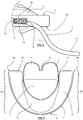
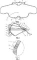
- the device according to the invention appears in various views at Figures 1 to 9 .
- the support is a gutter 8described below.
- the support according to the invention is fixable to the maxillary arch.
- Fixable means that the support is configured to be fixed in position at the maxillary arch.
- the support can be removable, it is not necessarily embedded on the maxillary arch.
- the support is a palatal plate still called fake palate.
- the palatal plate is a commonly resinous plate on which are fixed hooks and springs for cooperating with the teeth of the maxillary arch to hold the support in position.
- the blade 1 according to the invention is mounted on the palatal plate.
- Different type of mounting can be provided; for example, the blade 1 is connected to the palatal plate by lateral attachment points arranged substantially with respect to the upper lateral incisors or upper canines and at the level of the first upper molars.
- Fixing the blade 1 on the palatal plate may have an elasticity facilitating the deformation of the blade 1 and the placement of the tongue between the blade 1 and the palatal plate.
- the blade 1 is advantageously removable.
- the support is formed by dental rings.
- the blade 1 is mounted on the rings by lateral attachment points similar to what is described above for the palatal plate.
- the blade 1 is advantageously removable.
- the support is a bow which can be of contention fixed to the teeth.
- the blade 1 is mounted on the bow or on the arc attachment rings by lateral attachment points similar to what is described above for the palatal plate.
- the blade 1 is advantageously removable.
- the blade 1 is preferably mounted on the support so that once the support is in position fixed on the maxillary arch of the patient, the attachment points of the blade 1 on the support, at least to the before, are advantageously at the level of the upper incisors or possibly the canines and at the first molars, at the rear of the blade 1, the blade 1 being free between the front and rear attachment points.
- the support generally has a shape adapted to the contours of the upper dental arch of the user intended to receive the device.
- the device of the invention comprises, according to one embodiment, a channel 8 allowing at least one support of the upper jaw.
- the gutter 8 comprises a maxillary support surface 2.
- the maxillary bearing surface 2 is substantially flat. The maxillary support surface 2 allows the application of the teeth of the upper dental arch of the user.
- the groove 8 preferably comprises a mandibular support face 15 which may be substantially identical in configuration to the maxillary bearing surface 2, that is to say preferably flat.
- the channel 8 comprises two half-arches 3a, 3b, each placed on one side of the channel 8 around a front zone 4 making the junction between the two symmetrical half-arches 3a, 3b.
- the axis of symmetry of the two half-arches 3a, 3b corresponds to a median direction m of the gutter which cuts it into two equal parts.
- This direction "m” is visible in particular on the front view, figure 5 , and corresponds to the cutting plane BB.
- This median direction "m” corresponds to the intersection between the sagittal plane and a substantially horizontal plane in which at least approximately the maxillary support surface 2 is located.
- the two half-arches 3a, 3b terminate opposite the front zone 4 by posterior ends 9a, 9b substantially corresponding to the last molars of the patient.
- Gutter 1 is advantageously flexible and therefore elastically deformable as indicated above and can be made in different biocompatible materials and particularly silicone.
- the channel 8 constitutes a bite plane interposed between the upper arch and the lower arch. Its typical thickness is of the order of 2 to 4 millimeters.
- the channel 8 comprises a screen 7 and advantageously an upper posterior border 5.
- This border 5 and the screen 7 are positioned mainly in the front area 4 of the channel 8.
- the upper rear edge 5 is the edge arranged inside. the concavity of the channel 8 while the screen 7 is arranged outside the concavity of the channel 8.
- the screen 7 is for example intended to keep the lips away from the teeth.
- the upper posterior border 5 and the screen 7 follow the convexity 8.
- the border 5 and the screen 7 extend substantially in a plane perpendicular to the plane of the maxillary support surface 2.
- the border 5 and the screen 7 form anterior and posterior guides for the arcade dental maxillary, especially for guiding the teeth in the gutter 8.
- the screen 7 is located in the front zone of the device of the invention and constitutes the front part of the assembly. Its shape is advantageously convex.
- the convexity is executed not only in planes parallel to the sagittal plane but also in perpendicular planes.
- the screen 7 has a convexity in the sagittal plane and in the frontal plane. This convexity of the screen 7, more precisely these two convexities allow an advance of the gingivo-labial groove following a sagittal plane.
- the screen 7 comprises an upper panel 8 extending beyond the maxillary support surface 1 and advantageously a lower panel extending below the maxillary support surface 2. The screen 7 allows keeping the lips of the teeth at bay and thus preventing the lips from exerting harmful pressure on the teeth.
- the screen 7 may be provided with a through opening so as to facilitate the circulation of air.
- the screen 7 has a curvature 12 in the upper pan and a curvature 12 in the lower pan whose shape is preferably configured to respectively provide space for the upper labial brake and the lower labial brake and be atraumatic.
- the curvatures 12 form low points at the sagittal plane.
- the screen 7 is intended to be in contact by its outer face with the upper and lower lips of the user.
- the upper pan is intended to be in contact with the upper lip 1s while the lower pan is intended to be in contact with the lower lip li.
- the convex shape of the screen 7 is also intended to be atraumatic for the user who must wear this device over long periods of time, especially during the entire night.
- the screen 7 is configured to perfectly fit the outer shape of the upper dental arch.
- the screen 7 advantageously extends over almost the entire length of the gutter 8.
- the height of the screen 7 is advantageously decreasing from the front zone 4 of the gutter 8 towards the end of the half-arches 3a. 3b.
- the mandibular support face 15 is advantageously present with at least one flange projecting around said mandibular support face 15.
- the device comprises a rim lower lingual 13 able to lodge in the lower palace still called oral floor.
- the lower lingual flange 13 extending in the continuity of the upper posterior border 5 of the trough 8 below the maxillary bearing surface 2.
- the lower lingual flange 13 is formed of a substantially curved ply whose convexity is oriented towards the gutter 8.
- the lower lingual flange 13 is preferably in the form of a sector of sphere or hemisphere on an angular portion, for example less than a quarter of a sphere.
- the lower lingual flange 13 forms a guide for positioning the teeth of the mandibular dental arch and in particular the incisors in the groove 8 at the level of the mandibular support face 15.
- the lower lingual flange 13 extends according to one embodiment to a narrower angular sector than the angular sector on which the screen 7 extends.
- the lower lingual flange 13 extends over a sector angular of the order of 30 ° of the gutter 8.
- the device according to the invention typically comprises a blade 1.
- the description below is given for the embodiment illustrated in the figures and can be applied without difficulty to any support covered by the invention and in particular those described above. .
- the blade 1 extends from the front to the rear of the device and advantageously between the two half-arches 3a, 3b.
- the blade 1 is arranged at least partially above the maxillary support surface 2 thus ensuring a high position of the tongue.
- the blade 1 comprises a segment extending from the rear towards the front having a component in a sagittal plane and oriented upwards, that is to say in a direction extending beyond the maxillary support surface 2.
- This blade segment 1 is therefore oriented from the rear to the front and from the bottom to the top so as to advantageously guide the tip of the tongue atraumatically to a high position, it is ie the tip of the tongue behind the upper incisors in contact with the palate.
- This segment advantageously prevents the tongue from being in a low position, that is to say at the level of the floor of the mouth.
- the blade 1 is configured to ensure correct positioning of the tongue, that is to say the tip of the tongue behind the upper incisors in contact with the palate.
- the blade 1 extends from the front zone 4 of the trough preferably from the upper rear edge 5 towards the end of the two half-arches 3a-3b of the trough 8.
- the blade 1 is fixed to the trough 8 by several attachment points, more precisely advantageously at least one front attachment point at the front zone 4 of the upper rear edge 5, corresponding to the back of the roots of the upper central incisors when the device is in place in the patient's mouth.
- the blade 1 is advantageously also fixed by at least two rear attachment points at the end of the two half-arches 3a-3b, more precisely at the rear end of the upper rear edge 5.
- the blade 1 is fixed to bite plane of the gutter 8 at the lingual surfaces of the lower first molars when the device is in place in the patient's mouth.
- apart from these points of attachment front and rear blade 1 is free. This arrangement facilitates the deformation of the blade as described below.
- the blade 1 comprises at least one portion 10 elastically deformable.
- the blade 1 advantageously has a maximum height of between 0.7 and 1.5 cm.
- the height of the blade 1 is between its farthest point above the bite plane in a sagittal plane and said bite plane.
- the portion 10 of the blade 1 is configured to alternately take a rest position and preferably at least one position of tension or stress.
- the blade 1, in the tension position, is configured to return automatically to the rest position.
- the blade 1 is called shape memory, in that its deformation is elastic.
- the portion 10 is positioned at least partly above the maxillary bearing surface 2.
- the portion 10 comprises a concavity opposite to the maxillary bearing surface 2 in the rest position.
- the rest position is the stable position of the blade 1.
- the concave portion of the blade 1 is positioned at least partially above the maxillary bearing surface 2.
- the concavity is directed towards the top of the device that is to say the opposite of the maxillary support surface 2 beyond which the portion 10 protrudes.
- the portion 10 may be curvilinear, especially in an arc.
- the tongue is in the high position with the point positioned in contact with the upper palate behind the incisors.
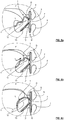
- the tongue is spread out and has a rounded tip as illustrated in figure 9b , the language is also flat. The tongue is properly maintained, even during swallowing.
- the portion 10, preferably at the concavity, in the rest position of the blade 1 is configured to receive and support the tip of the tongue in the high position.
- the portion 10 advantageously has a surface forming a support plate for a lower zone of the tongue. Preferably, this surface is smooth so as to facilitate the propulsion of the tip of the tongue upwards and forwards as well as to support the tongue atraumatically.
- this surface includes the highest point of said portion 10, that is to say the farthest point above the bite plane.
- tension position also called constrained position
- the blade 1 In tension position, also called constrained position, the blade 1 is in an unbalanced position.
- Portion 10 is deformed.
- This blade position 1 is illustrated in Figures 8a, 8b and 9a .
- the portion 10 has a convexity opposite to the concavity of the portion 10 in the rest position.
- the deformed portion is always positioned above the maxillary support surface 2.
- the blade 1 comprises an anterior portion, that is to say advantageously disposed between the front attachment point and the concave portion which also has a concavity.
- This concavity is an extension of the concavity of the portion 10 in the rest position and remains concave when the portion 10 is deformed in the constrained position.
- This anterior portion which remains concave whatever the position of the elastically deformable portion makes it possible to ensure this elastic deformation and the automatic resumption of the blade rest position 1.
- the blade 1 forms a partition separating the oral cavity into two compartments: an upper compartment, close to the palate and a lower compartment, close to the floor of the mouth and blocking access to the lower compartment.
- the blade 1 comprises a distal portion extending to the posterior end.
- the distal portion advantageously has, at least in the rest position, a curvature, or a concavity, opposite that of the portion 10.
- the blade 1 preferably has, at least in the rest position, two opposite curvatures.
- the blade 1 is configured to deform accordion during a push of the portion 10 by the tongue.
- the two curvatures are either arranged in the extension of one another giving a shape substantially S of the blade 1, or the blade comprises an inflection in the direction of the bite plane, between the concavity of the portion 10 and the opposite concavity of the rear end of the blade 1.
- the blade 1 extends beyond the rear fixing points located at the rear of the device.
- the extension of the blade makes it possible to ensure contact with the floor of the mouth.
- the blade 1 advantageously has a rounded edge and a median notch 6 configured to provide space for the lingual brake and be atraumatic and advantageously forming two tongues 11.
- the blade 1 extends beyond the attachment points, located at the rear of the device, and below the maxillary support surface 2.
- the tongues 11 are located under the maxillary support surface 2.
- the tongues 11, that is to say the lower atraumatic edge of the blade 1 are intended to be in contact with the floor of the mouth so as to prevent the passage of the tongue under the blade 1.
- the low position of the tongue is no longer possible because the lower compartment of the oral cavity is no longer accessible.
- the blade 1 advantageously comprises the anterior portion, then the elastically deformable portion 10, then the segment oriented from the rear towards the front and from the bottom upwards which can be optionally elastically deformable and part of the portion 10, then the distal or posterior portion comprising a possibility of the tabs 11 and preferably the central notch 6 to let the brake of the tongue.
- the blade 1 is a flexible blade.
- the thickness of the blade 1 is less than 2 mm, preferably 1 mm.
- the thickness of the blade 1 can be varied along a longitudinal axis of the blade 1.
- the blade 1 can be thinner at the rear end and / or thicker at the portion 10 so to be atraumatic and contribute to the elastic deformation of the portion 10.
- the blade 1 can be made of different biocompatible materials particularly silicone.
- the blade 1 has a curved shape, preferably in a plane perpendicular to the concavity, and advantageously at the curved portion 10. In this way, the blade 1 has a smaller width at the top of the portion 10, in rest position.
- the portion 10 advantageously has a constriction 14 on either side. This curved shape facilitates the deformation of the blade 1 and its return to the rest position.
- the blade 1 is movable upwards in the channel and advantageously has a width smaller than the space defined between the two half-arches 3a, 3b.
- the blade 1 is at least partially removable.
- the device comprises fastening means 16 of the blade 1 on the trough 8 and preferably on the upper rear edge 5. These fastening means 16 allow to fix the blade 1 and thus to form a springboard with tongue as described above to facilitate lingual positioning on a gutter 8 base for example on a conventional orthodontic appliance.
- these fixing means 16 are for example male-female systems such as notches and complementary projections on the upper posterior border 5 as illustrated in FIG. figure 7 and on the blade 1 as well as ends 9a, 9b of the two half-arches 3a-3b and on the blade 1. It is thus possible to form a base portion of device capable of selectively cooperating with one of several blades 8, in particular for a simple adaptation to different anatomies of users . Fixing is fast and simple.
- the device comprises adjustment means 17 of the curved portion 10.
- These adjustment means 17 are intended to allow a modification of the length and / or the height and / or the concavity of the curved portion 10 so that to best adapt to the morphology of each patient.
- the adjustment means 17 allow sliding of the blade 1 in complementary grooves formed in the groove 8 preferably on the lingual surface at the roots of the lower first molars.
- the adjusting means 17 comprise male / female fixing means and a slide, such as for example a pin 18 is formed on the blade 1 cooperating with mortises 19 in which is fixed the pin 18.
- the mortises 19 formed in the gutter 8 are connected by a slideway 20 in which the stud 18 slides.
- the practitioner can cut the lower end of the blade 1, preferably at the tongues 11, so as to limit any traumatic friction for the floor of the mouth.
- the mandible of the user who clamps the teeth is placed in the channel formed by the trough 8 at the maxillary support surface 2.
- the trough 8 enters the mouth of the user being contracted transversely between the thumb and forefinger.
- the tongue is then either directly in the high position in contact with the portion 10 of the blade 1 in the rest position, or the tongue pushes with its tip down on the portion 10 of the blade 1 causing its deformation in the tension position .
- the blade then returns the tip of the tongue upwards and forwards to return to its ideal rest position and position the tongue in the up position.
- the tongue grows on the blade 1 as illustrated in figure 8a , it has a narrow and pointed shape as illustrated in figure 9a .
- the device according to the invention is indicated to re-educate the position of the tongue at rest, during swallowing, day and night. At night, the tongue is plated in the palate and will not tend to relax obstructing the pharynx and vibrating the uvula generating snoring.
Landscapes
- Health & Medical Sciences (AREA)
- Otolaryngology (AREA)
- Pulmonology (AREA)
- Nursing (AREA)
- Orthopedic Medicine & Surgery (AREA)
- Engineering & Computer Science (AREA)
- Biomedical Technology (AREA)
- Heart & Thoracic Surgery (AREA)
- Vascular Medicine (AREA)
- Life Sciences & Earth Sciences (AREA)
- Animal Behavior & Ethology (AREA)
- General Health & Medical Sciences (AREA)
- Public Health (AREA)
- Veterinary Medicine (AREA)
- Orthopedics, Nursing, And Contraception (AREA)
Claims (15)
- Intraorale Vorrichtung zur Repositionierung und Rehabilitation der Zunge, umfassend einen Träger, der mit Bezug auf einen Kieferzahnbogen eines Patienten fixierbar ist, wobei die Vorrichtung eine Klinge (1) umfasst, die auf dem Träger montiert ist und sich gemäß einer Längsrichtung, die ausgelegt ist, um sich in eine saggitale Ebene des Patienten einzuschreiben, von einem hinteren Ende hin zu einem vorderen Ende erstreckt, dadurch gekennzeichnet, dass die Klinge (1) einen elastisch verformbaren Abschnitt (10) umfasst, der konfiguriert ist, um alternativ eine Ruheposition, in der sich der Abschnitt (10) mindestens teilweise außerhalb einer Bissebene des Patienten positioniert, und mindestens eine gespannte Position einzunehmen, in der der Abschnitt (10) in Richtung der Bissebene verformt ist.
- Vorrichtung nach dem vorhergehenden Anspruch, wobei der Abschnitt (10) ein Segment darstellt, das sich von hinten nach vorne erstreckt und einen Bestandteil aufweist, der auf eine saggitale Ebene ausgerichtet ist und sich von der Bissebene (2) entfernt.
- Vorrichtung nach einem der vorhergehenden Ansprüche, wobei der elastisch verformbare Abschnitt (10) mindestens teilweise gekrümmt ist.
- Vorrichtung nach einem der vorhergehenden Ansprüche, wobei der elastisch verformbare Abschnitt (10) eine Konkavität gegenüber der Bissebene (2) umfasst.
- Vorrichtung nach einem der vorhergehenden Ansprüche, wobei das hintere Ende der Klinge (1) konfiguriert ist, um auf den Mundboden angewendet zu werden.
- Vorrichtung nach einem der vorhergehenden Ansprüche, wobei das hintere Ende der Klinge (1) konfiguriert ist, um ein inneres Abteil zwischen dem Mundboden und der Klinge (1), der für die Zunge nicht zugänglich ist, zu begrenzen.
- Vorrichtung nach einem der vorhergehenden Ansprüche, umfassend Mittel zum Einstellen (17) des Abschnitts (10) der Klinge (1).
- Vorrichtung nach dem vorhergehenden Anspruch, wobei die Mittel zum Einstellen (17) Mittel umfassen, die das Gleiten der Klinge (1) in den Nuten, gebildet im Träger, sicherstellen.
- Vorrichtung nach einem der zwei vorhergehenden Ansprüche, wobei die Mittel zum Einstellen (17) des Abschnitts (10) der Klinge (1) eine Einstellung der Länge der Klinge (1) sicherstellen, um für den Mundboden atraumatisch zu sein.
- Vorrichtung nach einem der vorhergehenden Ansprüche, wobei in der gespannten Position der verformte Abschnitt (10) außerhalb der Bissebene (2) positioniert ist.
- Vorrichtung nach einem der vorhergehenden Ansprüche, wobei in der Ruheposition, der elastisch verformbare Abschnitt (10) eine Fläche umfasst, die konfiguriert ist, um die Zunge zu tragen.
- Vorrichtung nach einem der vorhergehenden Ansprüche, wobei die Klinge (1) einen vorderen Abschnitt umfasst, der konfiguriert ist, um in der Ruheposition und in der gespannten Position konkav zu sein, um die Rückkehr der Klinge in die Ruheposition sicherzustellen.
- Vorrichtung nach einem der vorhergehenden Ansprüche in Kombination mit Anspruch 4, wobei die Klinge (1) einen distalen Abschnitt umfasst, der sich bis zum hinteren Ende erstreckt und eine Krümmung gegenüber derjenigen des elastisch verformbaren Abschnitts (10) aufweist.
- Vorrichtung nach einem der vorhergehenden Ansprüche, umfassend mindestens einen Fixierungspunkt vor der Klinge (1) auf der Ebene der vorderen Zone des Trägers.
- Vorrichtung nach dem vorhergehenden Anspruch, wobei zwischen dem vorderen und hinteren Fixierungspunkt die Klinge (1) frei beweglich ist.
Applications Claiming Priority (2)
| Application Number | Priority Date | Filing Date | Title |
|---|---|---|---|
| FR1558729A FR3041242B1 (fr) | 2015-09-17 | 2015-09-17 | Dispositif intrabuccal destine au repositionnement et a la reeducation de la langue |
| PCT/EP2016/071734 WO2017046184A1 (fr) | 2015-09-17 | 2016-09-14 | Dispositif intrabuccal destiné au repositionnement et à la rééducation de la langue |
Publications (2)
| Publication Number | Publication Date |
|---|---|
| EP3349699A1 EP3349699A1 (de) | 2018-07-25 |
| EP3349699B1 true EP3349699B1 (de) | 2019-07-03 |
Family
ID=54356621
Family Applications (1)
| Application Number | Title | Priority Date | Filing Date |
|---|---|---|---|
| EP16766933.2A Active EP3349699B1 (de) | 2015-09-17 | 2016-09-14 | Intraorale vorrichtung zur repositionierung und rehabilitation der zunge |
Country Status (4)
| Country | Link |
|---|---|
| US (1) | US20180344507A1 (de) |
| EP (1) | EP3349699B1 (de) |
| FR (1) | FR3041242B1 (de) |
| WO (1) | WO2017046184A1 (de) |
Families Citing this family (5)
| Publication number | Priority date | Publication date | Assignee | Title |
|---|---|---|---|---|
| WO2019060624A2 (en) | 2017-09-22 | 2019-03-28 | Shah Mamta Ketan | SYSTEMS, METHODS AND DEVICES FOR TREATING DISORDERS OF THE MOUTH AND JAW |
| ES1224244Y (es) * | 2018-10-24 | 2019-04-25 | Segura Miguel Navarro | Férula intraoral con arco para evitar ronquidos y apneas. |
| MX2021009705A (es) * | 2019-02-14 | 2021-09-14 | Jaime C Salles | Mascarilla respiratoria protectora. |
| US11406527B2 (en) * | 2019-07-05 | 2022-08-09 | OptiO2 Labs LLC | Airflow inhibitor apparatus |
| US12458527B1 (en) | 2020-05-04 | 2025-11-04 | Mamta Ketan Shah | Systems, methods, and devices for treating mouth and jaw disorders |
Family Cites Families (5)
| Publication number | Priority date | Publication date | Assignee | Title |
|---|---|---|---|---|
| US6295988B1 (en) * | 1997-09-17 | 2001-10-02 | Steven K. Sue | Tongue lift and lip seal mouthpiece |
| RU2202313C2 (ru) * | 2001-04-02 | 2003-04-20 | Бредов Владимир Иванович | Устройство для предупреждения и лечения храпа и остановок дыхания во сне и предупреждения скрежетания зубами |
| US20080041396A1 (en) * | 2006-08-17 | 2008-02-21 | Lucker David A | Mouth appliance for mitigating sleep related problems |
| US8833374B2 (en) * | 2010-12-13 | 2014-09-16 | James S. Fallon | Intra-oral mandibular advancement appliance |
| FR2993450B1 (fr) * | 2012-07-19 | 2015-04-10 | Michel Alglave | Dispositif d'expansion d'un palais dans le plan transversal et frontal |
-
2015
- 2015-09-17 FR FR1558729A patent/FR3041242B1/fr not_active Expired - Fee Related
-
2016
- 2016-09-14 EP EP16766933.2A patent/EP3349699B1/de active Active
- 2016-09-14 WO PCT/EP2016/071734 patent/WO2017046184A1/fr not_active Ceased
- 2016-09-14 US US15/760,759 patent/US20180344507A1/en not_active Abandoned
Non-Patent Citations (1)
| Title |
|---|
| None * |
Also Published As
| Publication number | Publication date |
|---|---|
| US20180344507A1 (en) | 2018-12-06 |
| WO2017046184A1 (fr) | 2017-03-23 |
| FR3041242A1 (fr) | 2017-03-24 |
| FR3041242B1 (fr) | 2017-09-29 |
| EP3349699A1 (de) | 2018-07-25 |
Similar Documents
| Publication | Publication Date | Title |
|---|---|---|
| EP2693995B1 (de) | Funktionelle dentofaziale orthopädische vorrichtung | |
| EP2595563B1 (de) | Orthese mit einem oberen und unteren tray sowie einer verbindungsvorrichtung mit einstellbarer positionierung | |
| EP2081525B1 (de) | Vorrichtung zur erzeugung einer verschiebung des unterkiefers relativ zum oberkiefer | |
| WO2017046184A1 (fr) | Dispositif intrabuccal destiné au repositionnement et à la rééducation de la langue | |
| FR2831427A1 (fr) | Orthese intra-orale anti-ronflement | |
| EP1602347A1 (de) | Orthese zum Strecken des Kiefers. | |
| EP0845962A1 (de) | Intraorale vorrichtung | |
| EP3167852A1 (de) | Bissschiene, herstellungsverfahren und orthese, die eine solche bissschiene umfasst | |
| WO2014012827A1 (fr) | Dispositif d'expansion d'un palais dans le plan transversal et frontal | |
| EP2688543A1 (de) | Kieferorthopädischer schnuller | |
| EP3153136B1 (de) | Dynamische dentalvorrichtung | |
| EP3096717B1 (de) | Vorrichtung um die atmung durch die nase bei schnarchenden zu vereinfachen | |
| FR2867058A1 (fr) | Appareil de positionnement lingual | |
| FR3033999A1 (fr) | Dispositif d'intubation du type comportant une lame d'intubation | |
| FR2727008A1 (fr) | Appareil intrabuccal destine a fortement reduire les phenomenes de ronflement et d'apnee obstructive du sommeil, procede de fabrication d'un tel appareil et intercalaire pour ledit procede | |
| FR2893833A1 (fr) | Appareil d'orthopedie dento-faciale. | |
| FR3149770A1 (fr) | Dispositif orthodontique | |
| FR3145679A1 (fr) | Orthese d’avancee mandibulaire | |
| WO2004096076A1 (fr) | Porte-empreinte dentaire equipe de moyens de calage | |
| FR2971141A1 (fr) | Dispositif orthodontique a gouttieres reliees par une paire de languettes | |
| EP3201074A1 (de) | Mundstück zur abgabe von gasen an einen benutzer | |
| WO2015155464A1 (fr) | Appareil intra et exobuccal permettant de créer les conditions physiologiques nécessaires au sevrage des enfants | |
| FR3013585A1 (fr) | Ensemble d'ortheses guides |
Legal Events
| Date | Code | Title | Description |
|---|---|---|---|
| STAA | Information on the status of an ep patent application or granted ep patent |
Free format text: STATUS: THE INTERNATIONAL PUBLICATION HAS BEEN MADE |
|
| PUAI | Public reference made under article 153(3) epc to a published international application that has entered the european phase |
Free format text: ORIGINAL CODE: 0009012 |
|
| STAA | Information on the status of an ep patent application or granted ep patent |
Free format text: STATUS: REQUEST FOR EXAMINATION WAS MADE |
|
| 17P | Request for examination filed |
Effective date: 20180319 |
|
| AK | Designated contracting states |
Kind code of ref document: A1 Designated state(s): AL AT BE BG CH CY CZ DE DK EE ES FI FR GB GR HR HU IE IS IT LI LT LU LV MC MK MT NL NO PL PT RO RS SE SI SK SM TR |
|
| AX | Request for extension of the european patent |
Extension state: BA ME |
|
| DAV | Request for validation of the european patent (deleted) | ||
| DAX | Request for extension of the european patent (deleted) | ||
| GRAP | Despatch of communication of intention to grant a patent |
Free format text: ORIGINAL CODE: EPIDOSNIGR1 |
|
| STAA | Information on the status of an ep patent application or granted ep patent |
Free format text: STATUS: GRANT OF PATENT IS INTENDED |
|
| INTG | Intention to grant announced |
Effective date: 20190206 |
|
| RAP1 | Party data changed (applicant data changed or rights of an application transferred) |
Owner name: ALGLAVE, MICHEL |
|
| RIN1 | Information on inventor provided before grant (corrected) |
Inventor name: ALGLAVE, MICHEL |
|
| GRAS | Grant fee paid |
Free format text: ORIGINAL CODE: EPIDOSNIGR3 |
|
| GRAA | (expected) grant |
Free format text: ORIGINAL CODE: 0009210 |
|
| STAA | Information on the status of an ep patent application or granted ep patent |
Free format text: STATUS: THE PATENT HAS BEEN GRANTED |
|
| AK | Designated contracting states |
Kind code of ref document: B1 Designated state(s): AL AT BE BG CH CY CZ DE DK EE ES FI FR GB GR HR HU IE IS IT LI LT LU LV MC MK MT NL NO PL PT RO RS SE SI SK SM TR |
|
| REG | Reference to a national code |
Ref country code: GB Ref legal event code: FG4D Free format text: NOT ENGLISH |
|
| REG | Reference to a national code |
Ref country code: CH Ref legal event code: EP Ref country code: AT Ref legal event code: REF Ref document number: 1150084 Country of ref document: AT Kind code of ref document: T Effective date: 20190715 |
|
| REG | Reference to a national code |
Ref country code: IE Ref legal event code: FG4D Free format text: LANGUAGE OF EP DOCUMENT: FRENCH |
|
| REG | Reference to a national code |
Ref country code: DE Ref legal event code: R096 Ref document number: 602016016419 Country of ref document: DE |
|
| REG | Reference to a national code |
Ref country code: NL Ref legal event code: MP Effective date: 20190703 |
|
| REG | Reference to a national code |
Ref country code: LT Ref legal event code: MG4D |
|
| REG | Reference to a national code |
Ref country code: AT Ref legal event code: MK05 Ref document number: 1150084 Country of ref document: AT Kind code of ref document: T Effective date: 20190703 |
|
| PG25 | Lapsed in a contracting state [announced via postgrant information from national office to epo] |
Ref country code: CZ Free format text: LAPSE BECAUSE OF FAILURE TO SUBMIT A TRANSLATION OF THE DESCRIPTION OR TO PAY THE FEE WITHIN THE PRESCRIBED TIME-LIMIT Effective date: 20190703 Ref country code: AT Free format text: LAPSE BECAUSE OF FAILURE TO SUBMIT A TRANSLATION OF THE DESCRIPTION OR TO PAY THE FEE WITHIN THE PRESCRIBED TIME-LIMIT Effective date: 20190703 Ref country code: NL Free format text: LAPSE BECAUSE OF FAILURE TO SUBMIT A TRANSLATION OF THE DESCRIPTION OR TO PAY THE FEE WITHIN THE PRESCRIBED TIME-LIMIT Effective date: 20190703 Ref country code: BG Free format text: LAPSE BECAUSE OF FAILURE TO SUBMIT A TRANSLATION OF THE DESCRIPTION OR TO PAY THE FEE WITHIN THE PRESCRIBED TIME-LIMIT Effective date: 20191003 Ref country code: PT Free format text: LAPSE BECAUSE OF FAILURE TO SUBMIT A TRANSLATION OF THE DESCRIPTION OR TO PAY THE FEE WITHIN THE PRESCRIBED TIME-LIMIT Effective date: 20191104 Ref country code: HR Free format text: LAPSE BECAUSE OF FAILURE TO SUBMIT A TRANSLATION OF THE DESCRIPTION OR TO PAY THE FEE WITHIN THE PRESCRIBED TIME-LIMIT Effective date: 20190703 Ref country code: NO Free format text: LAPSE BECAUSE OF FAILURE TO SUBMIT A TRANSLATION OF THE DESCRIPTION OR TO PAY THE FEE WITHIN THE PRESCRIBED TIME-LIMIT Effective date: 20191003 Ref country code: LT Free format text: LAPSE BECAUSE OF FAILURE TO SUBMIT A TRANSLATION OF THE DESCRIPTION OR TO PAY THE FEE WITHIN THE PRESCRIBED TIME-LIMIT Effective date: 20190703 Ref country code: FI Free format text: LAPSE BECAUSE OF FAILURE TO SUBMIT A TRANSLATION OF THE DESCRIPTION OR TO PAY THE FEE WITHIN THE PRESCRIBED TIME-LIMIT Effective date: 20190703 Ref country code: SE Free format text: LAPSE BECAUSE OF FAILURE TO SUBMIT A TRANSLATION OF THE DESCRIPTION OR TO PAY THE FEE WITHIN THE PRESCRIBED TIME-LIMIT Effective date: 20190703 |
|
| PG25 | Lapsed in a contracting state [announced via postgrant information from national office to epo] |
Ref country code: IS Free format text: LAPSE BECAUSE OF FAILURE TO SUBMIT A TRANSLATION OF THE DESCRIPTION OR TO PAY THE FEE WITHIN THE PRESCRIBED TIME-LIMIT Effective date: 20191103 Ref country code: RS Free format text: LAPSE BECAUSE OF FAILURE TO SUBMIT A TRANSLATION OF THE DESCRIPTION OR TO PAY THE FEE WITHIN THE PRESCRIBED TIME-LIMIT Effective date: 20190703 Ref country code: LV Free format text: LAPSE BECAUSE OF FAILURE TO SUBMIT A TRANSLATION OF THE DESCRIPTION OR TO PAY THE FEE WITHIN THE PRESCRIBED TIME-LIMIT Effective date: 20190703 Ref country code: GR Free format text: LAPSE BECAUSE OF FAILURE TO SUBMIT A TRANSLATION OF THE DESCRIPTION OR TO PAY THE FEE WITHIN THE PRESCRIBED TIME-LIMIT Effective date: 20191004 Ref country code: AL Free format text: LAPSE BECAUSE OF FAILURE TO SUBMIT A TRANSLATION OF THE DESCRIPTION OR TO PAY THE FEE WITHIN THE PRESCRIBED TIME-LIMIT Effective date: 20190703 Ref country code: ES Free format text: LAPSE BECAUSE OF FAILURE TO SUBMIT A TRANSLATION OF THE DESCRIPTION OR TO PAY THE FEE WITHIN THE PRESCRIBED TIME-LIMIT Effective date: 20190703 |
|
| PG25 | Lapsed in a contracting state [announced via postgrant information from national office to epo] |
Ref country code: TR Free format text: LAPSE BECAUSE OF FAILURE TO SUBMIT A TRANSLATION OF THE DESCRIPTION OR TO PAY THE FEE WITHIN THE PRESCRIBED TIME-LIMIT Effective date: 20190703 |
|
| REG | Reference to a national code |
Ref country code: DE Ref legal event code: R119 Ref document number: 602016016419 Country of ref document: DE |
|
| PG25 | Lapsed in a contracting state [announced via postgrant information from national office to epo] |
Ref country code: RO Free format text: LAPSE BECAUSE OF FAILURE TO SUBMIT A TRANSLATION OF THE DESCRIPTION OR TO PAY THE FEE WITHIN THE PRESCRIBED TIME-LIMIT Effective date: 20190703 Ref country code: EE Free format text: LAPSE BECAUSE OF FAILURE TO SUBMIT A TRANSLATION OF THE DESCRIPTION OR TO PAY THE FEE WITHIN THE PRESCRIBED TIME-LIMIT Effective date: 20190703 Ref country code: DK Free format text: LAPSE BECAUSE OF FAILURE TO SUBMIT A TRANSLATION OF THE DESCRIPTION OR TO PAY THE FEE WITHIN THE PRESCRIBED TIME-LIMIT Effective date: 20190703 Ref country code: PL Free format text: LAPSE BECAUSE OF FAILURE TO SUBMIT A TRANSLATION OF THE DESCRIPTION OR TO PAY THE FEE WITHIN THE PRESCRIBED TIME-LIMIT Effective date: 20190703 |
|
| PG25 | Lapsed in a contracting state [announced via postgrant information from national office to epo] |
Ref country code: SK Free format text: LAPSE BECAUSE OF FAILURE TO SUBMIT A TRANSLATION OF THE DESCRIPTION OR TO PAY THE FEE WITHIN THE PRESCRIBED TIME-LIMIT Effective date: 20190703 Ref country code: MC Free format text: LAPSE BECAUSE OF FAILURE TO SUBMIT A TRANSLATION OF THE DESCRIPTION OR TO PAY THE FEE WITHIN THE PRESCRIBED TIME-LIMIT Effective date: 20190703 Ref country code: IS Free format text: LAPSE BECAUSE OF FAILURE TO SUBMIT A TRANSLATION OF THE DESCRIPTION OR TO PAY THE FEE WITHIN THE PRESCRIBED TIME-LIMIT Effective date: 20200224 Ref country code: SM Free format text: LAPSE BECAUSE OF FAILURE TO SUBMIT A TRANSLATION OF THE DESCRIPTION OR TO PAY THE FEE WITHIN THE PRESCRIBED TIME-LIMIT Effective date: 20190703 |
|
| REG | Reference to a national code |
Ref country code: CH Ref legal event code: PL |
|
| PLBE | No opposition filed within time limit |
Free format text: ORIGINAL CODE: 0009261 |
|
| STAA | Information on the status of an ep patent application or granted ep patent |
Free format text: STATUS: NO OPPOSITION FILED WITHIN TIME LIMIT |
|
| PG2D | Information on lapse in contracting state deleted |
Ref country code: IS |
|
| PG25 | Lapsed in a contracting state [announced via postgrant information from national office to epo] |
Ref country code: DE Free format text: LAPSE BECAUSE OF NON-PAYMENT OF DUE FEES Effective date: 20200401 Ref country code: LI Free format text: LAPSE BECAUSE OF NON-PAYMENT OF DUE FEES Effective date: 20190930 Ref country code: LU Free format text: LAPSE BECAUSE OF NON-PAYMENT OF DUE FEES Effective date: 20190914 Ref country code: CH Free format text: LAPSE BECAUSE OF NON-PAYMENT OF DUE FEES Effective date: 20190930 Ref country code: IE Free format text: LAPSE BECAUSE OF NON-PAYMENT OF DUE FEES Effective date: 20190914 |
|
| 26N | No opposition filed |
Effective date: 20200603 |
|
| PG25 | Lapsed in a contracting state [announced via postgrant information from national office to epo] |
Ref country code: SI Free format text: LAPSE BECAUSE OF FAILURE TO SUBMIT A TRANSLATION OF THE DESCRIPTION OR TO PAY THE FEE WITHIN THE PRESCRIBED TIME-LIMIT Effective date: 20190703 |
|
| GBPC | Gb: european patent ceased through non-payment of renewal fee |
Effective date: 20200914 |
|
| PG25 | Lapsed in a contracting state [announced via postgrant information from national office to epo] |
Ref country code: CY Free format text: LAPSE BECAUSE OF FAILURE TO SUBMIT A TRANSLATION OF THE DESCRIPTION OR TO PAY THE FEE WITHIN THE PRESCRIBED TIME-LIMIT Effective date: 20190703 |
|
| PG25 | Lapsed in a contracting state [announced via postgrant information from national office to epo] |
Ref country code: HU Free format text: LAPSE BECAUSE OF FAILURE TO SUBMIT A TRANSLATION OF THE DESCRIPTION OR TO PAY THE FEE WITHIN THE PRESCRIBED TIME-LIMIT; INVALID AB INITIO Effective date: 20160914 Ref country code: MT Free format text: LAPSE BECAUSE OF FAILURE TO SUBMIT A TRANSLATION OF THE DESCRIPTION OR TO PAY THE FEE WITHIN THE PRESCRIBED TIME-LIMIT Effective date: 20190703 |
|
| PG25 | Lapsed in a contracting state [announced via postgrant information from national office to epo] |
Ref country code: GB Free format text: LAPSE BECAUSE OF NON-PAYMENT OF DUE FEES Effective date: 20200914 |
|
| PG25 | Lapsed in a contracting state [announced via postgrant information from national office to epo] |
Ref country code: MK Free format text: LAPSE BECAUSE OF FAILURE TO SUBMIT A TRANSLATION OF THE DESCRIPTION OR TO PAY THE FEE WITHIN THE PRESCRIBED TIME-LIMIT Effective date: 20190703 |
|
| PGFP | Annual fee paid to national office [announced via postgrant information from national office to epo] |
Ref country code: IT Payment date: 20250910 Year of fee payment: 10 |
|
| PGFP | Annual fee paid to national office [announced via postgrant information from national office to epo] |
Ref country code: BE Payment date: 20250929 Year of fee payment: 10 |
|
| PGFP | Annual fee paid to national office [announced via postgrant information from national office to epo] |
Ref country code: FR Payment date: 20250926 Year of fee payment: 10 |