EP3349955B1 - Procédé et appareil de revêtement à bande sélectif pour appliquer un revêtement sur une face d'un premier sous-groupe sélectionné de bandes parallèles - Google Patents
Procédé et appareil de revêtement à bande sélectif pour appliquer un revêtement sur une face d'un premier sous-groupe sélectionné de bandes parallèles Download PDFInfo
- Publication number
- EP3349955B1 EP3349955B1 EP16846960.9A EP16846960A EP3349955B1 EP 3349955 B1 EP3349955 B1 EP 3349955B1 EP 16846960 A EP16846960 A EP 16846960A EP 3349955 B1 EP3349955 B1 EP 3349955B1
- Authority
- EP
- European Patent Office
- Prior art keywords
- strips
- group
- sub
- parallel strips
- strip
- Prior art date
- Legal status (The legal status is an assumption and is not a legal conclusion. Google has not performed a legal analysis and makes no representation as to the accuracy of the status listed.)
- Active
Links
Images

Classifications
-
- B—PERFORMING OPERATIONS; TRANSPORTING
- B27—WORKING OR PRESERVING WOOD OR SIMILAR MATERIAL; NAILING OR STAPLING MACHINES IN GENERAL
- B27M—WORKING OF WOOD NOT PROVIDED FOR IN SUBCLASSES B27B - B27L; MANUFACTURE OF SPECIFIC WOODEN ARTICLES
- B27M3/00—Manufacture or reconditioning of specific semi-finished or finished articles
- B27M3/0013—Manufacture or reconditioning of specific semi-finished or finished articles of composite or compound articles
- B27M3/0026—Manufacture or reconditioning of specific semi-finished or finished articles of composite or compound articles characterised by oblong elements connected laterally
- B27M3/0053—Manufacture or reconditioning of specific semi-finished or finished articles of composite or compound articles characterised by oblong elements connected laterally using glue
-
- B—PERFORMING OPERATIONS; TRANSPORTING
- B05—SPRAYING OR ATOMISING IN GENERAL; APPLYING FLUENT MATERIALS TO SURFACES, IN GENERAL
- B05C—APPARATUS FOR APPLYING FLUENT MATERIALS TO SURFACES, IN GENERAL
- B05C1/00—Apparatus in which liquid or other fluent material is applied to the surface of the work by contact with a member carrying the liquid or other fluent material, e.g. a porous member loaded with a liquid to be applied as a coating
- B05C1/02—Apparatus in which liquid or other fluent material is applied to the surface of the work by contact with a member carrying the liquid or other fluent material, e.g. a porous member loaded with a liquid to be applied as a coating for applying liquid or other fluent material to separate articles
- B05C1/027—Apparatus in which liquid or other fluent material is applied to the surface of the work by contact with a member carrying the liquid or other fluent material, e.g. a porous member loaded with a liquid to be applied as a coating for applying liquid or other fluent material to separate articles only at particular parts of the articles
-
- B—PERFORMING OPERATIONS; TRANSPORTING
- B05—SPRAYING OR ATOMISING IN GENERAL; APPLYING FLUENT MATERIALS TO SURFACES, IN GENERAL
- B05C—APPARATUS FOR APPLYING FLUENT MATERIALS TO SURFACES, IN GENERAL
- B05C1/00—Apparatus in which liquid or other fluent material is applied to the surface of the work by contact with a member carrying the liquid or other fluent material, e.g. a porous member loaded with a liquid to be applied as a coating
- B05C1/04—Apparatus in which liquid or other fluent material is applied to the surface of the work by contact with a member carrying the liquid or other fluent material, e.g. a porous member loaded with a liquid to be applied as a coating for applying liquid or other fluent material to work of indefinite length
- B05C1/16—Apparatus in which liquid or other fluent material is applied to the surface of the work by contact with a member carrying the liquid or other fluent material, e.g. a porous member loaded with a liquid to be applied as a coating for applying liquid or other fluent material to work of indefinite length only at particular parts of the work
-
- B—PERFORMING OPERATIONS; TRANSPORTING
- B27—WORKING OR PRESERVING WOOD OR SIMILAR MATERIAL; NAILING OR STAPLING MACHINES IN GENERAL
- B27G—ACCESSORY MACHINES OR APPARATUS FOR WORKING WOOD OR SIMILAR MATERIALS; TOOLS FOR WORKING WOOD OR SIMILAR MATERIALS; SAFETY DEVICES FOR WOOD WORKING MACHINES OR TOOLS
- B27G11/00—Applying adhesives or glue to surfaces of wood to be joined
-
- B—PERFORMING OPERATIONS; TRANSPORTING
- B27—WORKING OR PRESERVING WOOD OR SIMILAR MATERIAL; NAILING OR STAPLING MACHINES IN GENERAL
- B27M—WORKING OF WOOD NOT PROVIDED FOR IN SUBCLASSES B27B - B27L; MANUFACTURE OF SPECIFIC WOODEN ARTICLES
- B27M3/00—Manufacture or reconditioning of specific semi-finished or finished articles
- B27M3/0013—Manufacture or reconditioning of specific semi-finished or finished articles of composite or compound articles
- B27M3/0086—Manufacture or reconditioning of specific semi-finished or finished articles of composite or compound articles characterised by connecting using glue
-
- B—PERFORMING OPERATIONS; TRANSPORTING
- B27—WORKING OR PRESERVING WOOD OR SIMILAR MATERIAL; NAILING OR STAPLING MACHINES IN GENERAL
- B27N—MANUFACTURE BY DRY PROCESSES OF ARTICLES, WITH OR WITHOUT ORGANIC BINDING AGENTS, MADE FROM PARTICLES OR FIBRES CONSISTING OF WOOD OR OTHER LIGNOCELLULOSIC OR LIKE ORGANIC MATERIAL
- B27N3/00—Manufacture of substantially flat articles, e.g. boards, from particles or fibres
- B27N3/08—Moulding or pressing
- B27N3/18—Auxiliary operations, e.g. preheating, humidifying, cutting-off
-
- B—PERFORMING OPERATIONS; TRANSPORTING
- B32—LAYERED PRODUCTS
- B32B—LAYERED PRODUCTS, i.e. PRODUCTS BUILT-UP OF STRATA OF FLAT OR NON-FLAT, e.g. CELLULAR OR HONEYCOMB, FORM
- B32B37/00—Methods or apparatus for laminating, e.g. by curing or by ultrasonic bonding
- B32B37/14—Methods or apparatus for laminating, e.g. by curing or by ultrasonic bonding characterised by the properties of the layers
- B32B37/24—Methods or apparatus for laminating, e.g. by curing or by ultrasonic bonding characterised by the properties of the layers with at least one layer not being coherent before laminating, e.g. made up from granular material sprinkled onto a substrate
-
- B—PERFORMING OPERATIONS; TRANSPORTING
- B05—SPRAYING OR ATOMISING IN GENERAL; APPLYING FLUENT MATERIALS TO SURFACES, IN GENERAL
- B05C—APPARATUS FOR APPLYING FLUENT MATERIALS TO SURFACES, IN GENERAL
- B05C1/00—Apparatus in which liquid or other fluent material is applied to the surface of the work by contact with a member carrying the liquid or other fluent material, e.g. a porous member loaded with a liquid to be applied as a coating
- B05C1/04—Apparatus in which liquid or other fluent material is applied to the surface of the work by contact with a member carrying the liquid or other fluent material, e.g. a porous member loaded with a liquid to be applied as a coating for applying liquid or other fluent material to work of indefinite length
- B05C1/08—Apparatus in which liquid or other fluent material is applied to the surface of the work by contact with a member carrying the liquid or other fluent material, e.g. a porous member loaded with a liquid to be applied as a coating for applying liquid or other fluent material to work of indefinite length using a roller or other rotating member which contacts the work along a generating line
- B05C1/0821—Apparatus in which liquid or other fluent material is applied to the surface of the work by contact with a member carrying the liquid or other fluent material, e.g. a porous member loaded with a liquid to be applied as a coating for applying liquid or other fluent material to work of indefinite length using a roller or other rotating member which contacts the work along a generating line characterised by driving means for rollers or work
-
- B—PERFORMING OPERATIONS; TRANSPORTING
- B27—WORKING OR PRESERVING WOOD OR SIMILAR MATERIAL; NAILING OR STAPLING MACHINES IN GENERAL
- B27N—MANUFACTURE BY DRY PROCESSES OF ARTICLES, WITH OR WITHOUT ORGANIC BINDING AGENTS, MADE FROM PARTICLES OR FIBRES CONSISTING OF WOOD OR OTHER LIGNOCELLULOSIC OR LIKE ORGANIC MATERIAL
- B27N7/00—After-treatment, e.g. reducing swelling or shrinkage, surfacing; Protecting the edges of boards against access of humidity
- B27N7/005—Coating boards, e.g. with a finishing or decorating layer
Definitions
- the present invention relates to a method of applying a coating to one face of a selected first sub-group of parallel strips, the selected first sub-group of parallel strips comprising at least two parallel strips and being selected from a plurality of parallel strips advanced in a side by side relationship from a first support member to a second support member, at least two strips of said plurality of parallel strips not belonging to said selected first sub-group of parallel strips forming a second sub-group of parallel strips.
- a selective strip coating apparatus for applying a coating to one face of a selected first sub-group of parallel strips, the selected first sub-group of parallel strips comprising at least two parallel strips and being selected from a plurality of parallel strips advanced in a side by side relationship from a first support member to a second support member, at least two strips of said plurality of parallel strips not belonging to said selected first sub-group of parallel strips forming a second sub-group of parallel strips.
- a rod manufacturing apparatus which comprises the selective strip coating apparatus.
- low weight elements are widely used. Such elements usually consist of a hollow body having two parallel large sheets spaced apart by a lightweight filling material.
- a lightweight filling material is formed by strips of a wooden material, preferably a material selected among High Density Fiberboard (HDF) and Medium Density Fiberboard (MDF). The strips extend widthwise between the two sheets of the hollow body and the edges of the strips are glued to the two sheets.
- the lightweight filling material includes wooden rods attached by gluing to the side edges of the two sheets to interconnect the two sheets to each other.
- Such low weight elements can be used as building elements, door panels, and a large amount of furniture elements. Consequently, a plurality of manufacturing methods for such low weight elements have been presented.
- a method of continuous manufacture of a composite hollow board material comprising a first surface and a second surface, and between the first and second surfaces a plurality of distance members is disclosed in US 8,999,094 (Pettersson et al. ).
- the method comprises providing material for the first surface from a first reel via a first guide roller towards an output lane; providing material for the second surface from a second reel via a second guide roller towards the output lane; and providing material for the distance members from a third reel towards the output lane such that the distance members comprises strips arranged, at any cross section perpendicular to the first and second surfaces and the direction of the output lane, perpendicular to the first and second surfaces and continuous along the output lane.
- the providing of material for the distance members comprises guiding at least some of the strips in a meandering pattern, and applying an adhesive to contact the strips on opposite edges thereof such that adhesion to the material of the first and second surfaces is enabled.
- the first and second guide rollers press the material of the first and second surfaces to the opposite edges of the strips, respectively, such that the material of the first and second surfaces are adhered to the strips.
- a plurality of strips may be joined by adhesive to form a lath or rod to be used as a distance member in the composite hollow board material.
- the part for preparing the lath or rod can include a cutting mechanism for cutting a sheet material into a plurality of strips.
- the preparation part comprises a guide mechanism for assembling the strips to run in parallel towards the output lane.
- An adhesive application mechanism applies adhesive such that the parallel strips can be adhered to each other.
- the preparation part also comprises a press mechanism such that the sandwiched parallel strips, after application of the adhesive, are pressed together and thus adhered to each other such that the lath or rod is achieved.
- the object of the present invention is to provide cost efficient and flexible joining of strips to form distance elements of different dimensions, such as rods or laths to be used in low weight building elements for furniture.
- the method comprises:
- the method further comprises arranging the plurality of parallel strips in a pattern of strip-groups, where each strip-group contains at least one, and more preferably at least two, neighboring strip(s) from the selected first sub-group of parallel strips to be coated and at least one strip from the second sub-group of parallel strips to remain uncoated.
- each strip-group contains at least one, and more preferably at least two, neighboring strip(s) from the selected first sub-group of parallel strips to be coated and at least one strip from the second sub-group of parallel strips to remain uncoated.
- the method further comprises:
- the coating that is applied to the selected first sub-group of parallel strips suitably is an adhesive type of coating.
- the strips are made from a wooden material, preferably a material selected among High Density Fiberboard (HDF) and Medium Density Fiberboard (MDF).
- HDF High Density Fiberboard
- MDF Medium Density Fiberboard
- the plurality of parallel strips are, downstream of the first support member, arranged in clusters, each such cluster comprising at least two, more preferably at least three, strips, the strips of each such cluster being pressed together to form a rod having a sandwiched structure.
- each such cluster comprising at least two, more preferably at least three, strips, the strips of each such cluster being pressed together to form a rod having a sandwiched structure.
- each cluster comprises at least one, more preferably two to twenty, and most preferably two to eight, strip(s) of the selected first sub-group of parallel strips and exactly one strip of the second sub-group of parallel strips.
- the selective strip coating apparatus comprises:
- the support bar has the form of a support roll.
- the support roll is a rotary support roll adapted to rotate around its central axis as the first sub-group of strips are carried by the respective ridge surfaces, and the ridge surfaces and the grooves extend circumferentially around the rotary support roll.
- a rotary support roll for the support bar makes the apparatus less sensitive to functional trouble.
- the coating device suitably is an adhesive coating device.
- the grooves in the support bar suitably are arranged in such a way that the ridge surfaces between two adjacent grooves will receive a plurality of the strips of the selected first sub-group of parallel strips to be coated.
- the grooves and the ridge surfaces are preferably arranged in such a way that they form a pattern of strip-groups, where each strip-group will receive at least one strip of the first sub-group to be coated and at least one strip of the second sub-group that is to remain uncoated.
- each strip-group will receive at least one strip of the first sub-group to be coated and at least one strip of the second sub-group that is to remain uncoated.
- each strip-group is suitably adapted to receive from two to twenty, more preferably two to eight, strips of the first sub-group to be coated and at least one, and more preferably exactly one, strip of the second sub-group that is to remain uncoated.
- Clusters of three to twenty-one, more preferably three to nine, strips include most of the desired rod widths.
- a cluster of more than twenty-one, or nine, strips would consume a relatively high amount of coating, such as an adhesive, to adhere the strips to each other, which would make the solution less environmentally friendly.
- the apparatus is provided with at least two separate support bars, each of said at least two separate support bars having its own unique arrangement of ridge surfaces and grooves, the apparatus having a selection arrangement for bringing one of said at least two separate support bars at a time into position for functioning as the first support member.
- the apparatus can be adjusted, in an efficient manner, from producing rods having one combination of width and height of the rods to produce rods having another combination of width and height of the rods.
- the selection arrangement preferably comprises a rotary magazine holding a plurality of parallel support bars, the magazine being a rotary device having a central axis of rotation parallel to central axes of the individual support bars, wherein each support bar has a unique arrangement of ridge surfaces and grooves.
- the magazine resembles a revolver magazine and holds at least three parallel and rotary support rolls, each of which has a unique arrangement of ridge surfaces and grooves.
- the object of the invention is achieved in that the rod manufacturing apparatus further comprises a rod pressing arrangement located downstream of the selective strip coating apparatus and adapted for pressing clusters of strips together to form sandwiched rod structures. By pressing the clusters of strips together to form sandwiched rod structures the joining of the strips is finished and a cost efficient and flexible joining of strips is provided.
- the rod manufacturing apparatus further comprises a strip cutting device that is located upstream of the support bar and is adapted for cutting the plurality of parallel strips from a web-shaped board material.
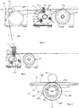
- Fig. 1 shows schematically a selective strip coating apparatus according to a preferred embodiment of the present invention and comprising a first support member 20 and a second support member 31 located downstream of the first support member 20.
- the strip coating apparatus includes a coater 4 for applying a coating to one face of a selected first sub-group 100 of parallel strips 10 when the selected sub group is supported by the first support member 20.
- the selected first sub-group 100 comprises at least two parallel strips 10 and is selected from a plurality of parallel strips 10, 11 advanced in a side by side relationship from the first support member 20 to the second support member 31. At least two strips 11 of said plurality of parallel strips 10, 11 not belonging to said selected first sub-group 100 of parallel strips 10 forming a second sub-group 110 of parallel strips 11.
- the parallel strips 10 of the selected first sub-group 100 are advanced along a first path between the first 20 and second 31 support members.
- the first path extends from a first point 200, being located adjacent to the first support member 20 and at a first distance R (shown in Fig. 3 ) from a longitudinal axis LA of the first support member 20, to a second point 310, being located adjacent to the second support member 31.
- the second sub-group 110 of parallel strips 11 is advanced along a second path between the first 20 and second 31 support members.
- the second path extends from a third point 201, that is located adjacent to the first support member 20 and at a second distance r (shown in Fig.
- the coating is applied by means of a coating device 4, which in Fig. 1 is represented by a coating roll 40 included in the coating device 4.
- the coating device 4 is in coating contact with the selected first sub-group 100 of parallel strips 10 passing the first support member 20 at the first distance R to coat one side of the strips 10 of the selected first sub-group 100 of parallel strips 10, 11, while the strips 11 of the second sub-group 110 of parallel strips that simultaneously pass the first support member 20 at the second distance r are out of reach of the coating device 4 and remain uncoated.
- an additional support member 30 for the strips 10, 11 is provided upstream of the first support member 31.
- the additional support member 30 forms part of a strip cutting device 32 which additionally comprises first and second cutting arrangements 33, 34 that use the support member 30 as an anvil and cuts the strips 10, 11 from a material web WB, for example a web of High Density Fiberboard (HDF) or Medium Density Fiberboard (MDF).
- the horizontal positions of the first and second cutting arrangements 33, 34 could be adjusted to obtain different widths of the strips 10, 11 formed by the cutting.
- the width of the strips 10, 11 as formed in the strip cutting device 32 will correspond to the height of the rods or laths formed downstream of the second support member 31, as described in more detail hereinafter.
- All three support members, 30, 20, and 31 may be support bars, but preferably they are rotary rolls, and more preferred powered rotary rolls that assist in pulling/forwarding some strips 10, 11.
- the first support member 20 could be varied, and there may be, e.g., two alternative rolls 21, 22, and in this connection it may be beneficial to use a combined motor and transmission for all rolls 20, 21, 22, to have them jointly driven, which eliminates any need of start-up time and simplifies the design.
- the strips 10, 11 run under tension from support member 30 to support member 20 and further to support member 31. At support member 20, the group 100 of strips 10 to be coated is lifted a distance of R - r above the level of group 110 of strips 11 that are not to be coated.
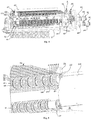
- the first support member 20 is provided in the form of a support bar having a longitudinal axis LA and a plurality of ridge surfaces 203 located at the first distance R from the longitudinal axis LA of the first support member 20 and a plurality of grooves 204 arranged between the ridge surfaces 203 and located at the second distance r from the longitudinal axis LA of the first support member 20, as is best shown in Fig. 3 .
- each one of the strips 10 of the selected first sub-group 100 of parallel strips is forwarded on a respective one of the ridge surfaces 203 to be in contact with the coating device 4 to coat a face of the strips 10 of the first sub-group 100 of parallel strips, and each one of the strips 11 of the second sub-group 110 of parallel strips is forwarded in one of the grooves 204 to remain out of reach of the coating device 4.
- the plurality of parallel strips 10. 11 preferably is arranged in a pattern of strip-groups 120, where each strip-group 120 contains at least one, and preferably at least two neighboring strips 10 from the selected first sub-group 100 of parallel strips to be coated and at least one strip 11 from the second sub-group 110 of parallel strips to remain uncoated.
- each strip-group 120 contains at least one, and preferably at least two neighboring strips 10 from the selected first sub-group 100 of parallel strips to be coated and at least one strip 11 from the second sub-group 110 of parallel strips to remain uncoated.
- each such cluster 121 and 121' comprises at least two strips 10, 11.
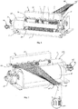
- the strips of each such cluster 121, 121' are being pressed together (see figure 8 ) by means of a rod pressing arrangement 6 to form respective rods, each such rod having a sandwiched structure comprising strips 10 and 11.
- the coating that is applied to the selected first sub-group 100 of parallel strips 10 by means of the coating device 4 preferably is an adhesive type of coating.
- the strips 10, 11 suitably are made from a wooden material, preferably a material selected among High Density Fiberboard (HDF) and Medium Density Fiberboard (MDF) and may be of a thickness of about 1 to 5 mm, more often about 2 to 3 mm, and cut, by means of the strip cutting device 32, to a constant width in the range of about 7-30 mm, preferably about 10-25 mm.
- HDF High Density Fiberboard
- MDF Medium Density Fiberboard
- the apparatus for applying a coating to one face of a selected first sub-group 100 of parallel strips 10 comprises a support bar forming the first support member 20.
- the support bar 20 has a longitudinal axis LA and a plurality of ridge surfaces 203 located at a first distance R (shown in Fig. 3 ) from the axis of the support bar 20 and adapted for carrying strips 10 of the selected first sub-group 100 of parallel strips, and a plurality of grooves 204 arranged adjacent the ridge surfaces 203 and located at a second distance r (shown in Fig. 3 ) from the axis of the support bar 20.
- the second distance r is shorter than the first distance R and adapted for housing strips of the second sub-group 110 of parallel strips 11.
- the apparatus comprises a coating device 4 positioned to be in operative contact with the strips 10 of the selected first sub-group 100 of strips carried by the respective ridge surfaces 203 of the support bar 20, while the strips 11 of the second sub-group 110 of strips will be carried in the grooves 204 and out of reach of the coating device 4 and remain uncoated.
- the support bar suitably has the form of a support roll 20, and the support roll preferably is a rotary support roll 20 adapted to rotate around its central axis LA, see Fig. 3 , as the strips 10 of the first sub-group 100 are carried by the respective ridge surfaces 203.
- the ridge surfaces 203 and the grooves 204 extend circumferentially around the rotary support roll 20, as best illustrated in Fig. 5 .
- the rotary support roll 20 comprises a tubular shaft base 23' and a plurality of flange-like rings or discs 205 of outer radius R that are mounted on the shaft base 23' and have peripheral surfaces forming said ridge surfaces 203.
- the bottom the grooves 204 may be formed by the peripheral surface of the shaft base 23', if desired, but preferably a plurality of flange-like rings or discs 206 of outer radius r are mounted on the shaft base 23' and have peripheral surfaces forming the bottom surfaces of the grooves 204.
- the flange-like rings or discs 205 and 206 are pressed axially against one another by means of screws (not shown) at least one end of the shaft base 23'.
- the coating device 4 preferably is an adhesive coating device having a reservoir 41 as shown in Figs. 2 and 6-8 for the adhesive, and the reservoir 41 has a bottom slot, in which a rotary coating roll 40 is mounted for transferring the adhesive from the reservoir 41 to the strips 10.
- the rotary coating roll 40 has a comparatively small diameter and may suitably have various structures on its peripheral surface.
- the roll 40 forms a bottom of the adhesive coating device 4, and a first doctor (not shown) makes sure that the downwards facing surface of the roll 40 carries an adhesive layer of desired thickness. Where the roll 40 touches the strips 10, the adhesive is being transferred to the strips 10.
- Adhesive remaining on the roll 40 is returned to the reservoir 41 past a second doctor (not shown), which may be set with a different gap toward the roll 40 than the first doctor, to supply a desired amount of adhesive as is known per se. Also the rotational speed of the roll 40 may be adjusted to increase or reduce the amount of adhesive, and more or less deep structural patterns in the peripheral surface of the roll 40 may be used to supply the desired amount of adhesive. This method of applying the adhesive is very well suited for this application, where strips 11 not to be coated are located at different locations along the roll 40.
- the grooves 204 in the support bar or roll 20 suitably are arranged in such a way that the ridge surfaces 203 between two adjacent grooves 204 will receive at least one, and preferably two to twenty, more preferably two to eight, of the strips 10 of the selected first sub-group 100 of parallel strips to be coated. Further, as is best shown in Figs. 4-6 , the grooves 204 and the ridge surfaces 203 are preferably arranged in such a way that they form a pattern of strip receiving ring or disc groups 207 corresponding to the strip-groups 120, where each strip receiving ring or disc group 207 will receive at least one strip 10 of the first sub-group 100 to be coated and at least one strip 11 of the second sub-group 110 that is to remain uncoated.
- Each strip receiving ring or disc group 207 is suitably adapted to receive at least one, more preferably from two to twenty, even more preferably two to eight, strips 10 of the first sub-group 100 to be coated and at least one, more preferably exactly one, strip 11 of the second sub-group 110 that is to remain uncoated.
- Clusters 121 of three to twenty-one, more preferably three to nine, strips include most of the desired rod widths.
- the apparatus is provided with at least two separate support bars or rolls 20, 21, 22 each of said at least two separate support bars or rolls 20, 21, 22 having its own unique arrangement of ridge surfaces 203 and grooves 204, and the apparatus has a selection arrangement 2, as illustrated in Fig. 4 , for bringing one of said at least two separate support bars or rolls 20, 21, 22 at a time into position for functioning as the first support member 20.
- the apparatus can, as an example, be changed from producing a first type of rods or laths having one combination of width and height, e.g.
- the selection arrangement preferably comprises a rotary magazine 2 holding a plurality of parallel support bars or rolls 20, 21, 22, the magazine 2 being a rotary device having a central axis RCA of rotation parallel to central axes of the individual support bars or rolls, and each support bar or roll 20, 21, 22 suitably has a unique arrangement of ridge surfaces 203 and grooves 204.
- the magazine 2 resembles a revolver "magazine” (i.e. a handgun revolving cylinder containing multiple chambers for rounds) and holds at least three parallel and rotary support rolls 20, 21, 22 each of which has a unique arrangement of ridge surfaces 203 and grooves 204.
- the magazine 2 has a central tubular shaft 23 and at a driven end of the shaft 23 a flange arrangement including two spaced apart large flanges 230, 231 for supporting one end of each of the support rolls 20, 21, 22 and at the other end of the shaft 23 a smaller flange 235 having an adjustable lug 232 for each one of the opposite ends of the three support rolls 20, 21, 22.
- a drive 26 is provided for rotating the magazine 2.
- the drive 26 includes a motor 260 driving a transmission 261 connected to the central tubular shaft 23 for rotating it.
- the transmission 261 may be a planetary gearing to give a desired reduction of the speed of the motor 260.
- a drive 25 is provided for rotating the support rolls 20, 21, 22.
- the drive 25 includes a motor 250 driving a transmission 251 connected to all of the three support rolls 20, 21, 22 for rotating them.
- the transmission 251 includes a common central ring gear mounted in bearings on the central tubular shaft 23, a gear that is carried by an output shaft of the motor 250, the proximate end of each one of the support rolls 20, 21, 22 includes a gear, and toothed belts transmits the rotation of the gear on the motor 250 to the common central ring gear and from there to the gears of the support rolls 20, 21, 22.
- the two ends of the central tubular shaft 23 is mounted in bearings carried by a stand 27, and the belts and gears of transmission 251 are located between the stand 27 and the outer flange 230.
- the selective strip coating apparatus preferably is included in a rod manufacturing apparatus in that a rod pressing arrangement 5 is located downstream of the selective strip coating apparatus and adapted for pressing said clusters 121 of strips 10, 11 together to form sandwiched rod structures.
- a rod pressing arrangement 5 is located downstream of the selective strip coating apparatus and adapted for pressing said clusters 121 of strips 10, 11 together to form sandwiched rod structures.
- the rod manufacturing apparatus further comprises the strip cutting device 32 that is located upstream of the selective strip coating apparatus and adapted for cutting the plurality of parallel strips 10, 11 from the web-shaped board material WB.
- Equipment for such cutting is previously known and requires no detailed description in the present specification.
- the present invention is applicable for producing distance elements of different dimensions, such as rods or laths to be used in low weight building elements for furniture.
Landscapes
- Life Sciences & Earth Sciences (AREA)
- Engineering & Computer Science (AREA)
- Wood Science & Technology (AREA)
- Forests & Forestry (AREA)
- Manufacturing & Machinery (AREA)
- Mechanical Engineering (AREA)
- Coating Apparatus (AREA)
- Application Of Or Painting With Fluid Materials (AREA)
Claims (19)
- Procédé d'application d'un revêtement à une face d'un premier sous-groupe sélectionné (100) de rubans parallèles (10), le premier sous-groupe sélectionné (100) de rubans parallèles comprenant au moins deux rubans parallèles (10) et étant sélectionné parmi des rubans d'une pluralité de rubans parallèles (10, 11) avancés dans une relation côte à côte d'un premier élément support (20) à un second élément support (31), au moins deux rubans (11) de ladite pluralité de rubans parallèles n'appartenant pas audit premier sous-groupe sélectionné (100) de rubans parallèles (10, 11) formant un second sous-groupe (110) de rubans parallèles, le procédé étant caractérisé en ce qu'il comprend :- avancer le premier sous-groupe sélectionné (100) de rubans parallèles le long d'un premier trajet entre les premier (20) et second (31) éléments supports, ledit premier trajet s'étendant d'un premier point (200), situé adjacent au premier élément support (20) et à une première distance (R) d'un axe longitudinal (LA) du premier élément support (20) à un deuxième point (310), situé adjacent au second élément support (31) ;- simultanément à ladite avance du premier sous-groupe sélectionné (100), avancer le second sous-groupe (110) de rubans parallèles (11) le long d'un second trajet entre les premier (20) et second (31) éléments supports, ledit second trajet s'étendant d'un troisième point (201), situé adjacent au premier élément support (20) et à une seconde distance (r) dudit axe longitudinal (LA) du premier élément support (20), ladite seconde distance (r) étant plus courte que ladite première distance (R), à un quatrième point (311) adjacent au second élément support (31) ; et- appliquer le revêtement au moyen d'un dispositif de revêtement (4) en contact avec le premier sous-groupe sélectionné (100) de rubans parallèles (10) en faisant passer le premier élément support (20) à la première distance (R) de façon à revêtir un côté des rubans (10) du premier sous-groupe sélectionné (100) de rubans parallèles, tandis que les rubans (11) du second sous-groupe (110) de rubans parallèles passant simultanément sur le premier élément support (20) à la seconde distance (r) étant hors d'atteinte du dispositif de revêtement (4) et demeurant non revêtus.
- Procédé selon la revendication 1, comprenant en outre l'étape consistant à :- organiser les rubans de la pluralité de rubans parallèles (10, 11) selon un motif de groupes de rubans (120), dans lequel chaque groupe de rubans (120) contient au moins un, et plus idéalement au moins deux, rubans voisins (10) issus du premier sous-groupe sélectionné (100) de rubans parallèles devant être revêtus, et au moins un ruban (11) issu du second sous-groupe (110) de rubans parallèles qui demeure non revêtu.
- Procédé selon la revendication 1 ou la revendication 2, comprenant en outre:- réaliser ledit premier élément support (20) sous la forme d'une barre de support comportant un axe longitudinal (LA) et une pluralité de surfaces nervurées (203) situées à la première distance (R) de l'axe longitudinal (LA) du premier élément support (20) et une pluralité de rainures (204) ménagées entre les surfaces nervurées (203) et situées à la seconde distance (r) de l'axe longitudinal (LA) du premier élément support (20) ;- transférer individuellement tous les rubans (10) du premier sous-groupe sélectionné (100) de rubans parallèles sur une surface respective des surfaces nervurées (203) de sorte qu'ils se trouvent en contact avec le dispositif de revêtement (4) à des fins de revêtement d'une face des rubans (10) du premier sous-groupe (100) de rubans parallèles ; et- transférer individuellement tous les rubans (11) du second sous-groupe (110) de rubans parallèles dans l'une des rainures (204) de sorte qu'ils demeurent hors d'atteinte du dispositif de revêtement (4).
- Procédé selon l'une quelconque des revendications 1 à 3, dans lequel le revêtement appliqué au premier sous-groupe sélectionné (100) de rubans parallèles (10) est un revêtement de type adhésif.
- Procédé selon l'une quelconque des revendications 1 à 4, dans lequel les rubans (10, 11) sont constitués d'un matériau de bois, idéalement d'un matériau sélectionné entre un panneau de fibres à haute densité (HDF) et un panneau de fibres à densité moyenne (MDF).
- Procédé selon l'une quelconque des revendications 1 à 5, dans lequel les rubans de la pluralité de rubans parallèles (10, 11) sont, en aval du premier élément support (20), organisés en groupes (121), chacun de ces groupes (121) comprenant au moins deux, idéalement au moins trois, rubans (10, 11), les rubans de chacun de ces groupes (121) étant pressés conjointement pour former une tige ou une latte ayant une structure en sandwich.
- Procédé selon la revendication 6, dans lequel chaque groupe (121) comprend au moins un, et plus idéalement deux à vingt rubans (10) du premier groupe sélectionné (100) de rubans parallèles (10) et exactement un ruban (11) du second sous-groupe (110) de rubans parallèles.
- Appareil de revêtement sélectif de rubans destiné à appliquer un revêtement à une face d'un premier sous-groupe sélectionné (100) de rubans parallèles (10), le premier sous-groupe sélectionné (100) de rubans parallèles comprenant au moins deux rubans parallèles (10) et étant sélectionné à partir d'une pluralité de rubans parallèles (10, 11) avancés dans une relation côte à côte d'un premier élément support (20) à un second élément support (31), au moins deux rubans (11) de ladite pluralité de rubans parallèles (10, 11) n'appartenant pas audit premier sous-groupe sélectionné (100) de rubans parallèles (10) formant un second sous-groupe (110) de rubans parallèles (11), l'appareil étant caractérisé en ce qu'il comprend :- une barre de support (20) formant le premier élément support et comportant un axe longitudinal (LA) et une pluralité de surfaces nervurées (203) situées à une première distance (R) de l'axe (LA) de la barre de support (20) et étant aptes à transporter des rubans (10) du premier sous-groupe sélectionné (100) de rubans parallèles, et une pluralité de rainures (204) ménagées adjacentes aux surfaces nervurées (203) et situées à une seconde distance (r) de l'axe (LA) de la barre de support (20), ladite seconde distance (r) étant plus courte que ladite première distance (R), lesdites rainures (204) étant aptes à loger des rubans (11) du second sous-groupe (110) de rubans parallèles ; et un dispositif de revêtement (4) positionné pour se trouver en contact fonctionnel avec les rubans (10) du premier sous-groupe sélectionné (100) de rubans transportés par les surfaces nervurées respectives (203) de la barre de support (20), tandis que les rubans (11) du second sous-groupe (110) de rubans seront transportés dans les rainures (204) et hors d'atteinte du dispositif de revêtement (4) et demeureront non revêtus.
- Appareil selon la revendication 8, dans lequel l'appareil comprend en outre un dispositif de coupe de rubans (32) situé en amont de la barre de support (20) et apte à couper les rubans de la pluralité de rubans parallèles (10, 11) à partir d'un matériau de panneau de fibres sous forme de bande (WB).
- Appareil selon la revendication 8 ou 9, dans lequel la barre de support (20) a la forme d'un rouleau de support, idéalement conçu pour appliquer une force de traction à au moins certains des rubans (10).
- Appareil selon la revendication 10, dans lequel le rouleau de support est un rouleau de support rotatif (20) apte à tourner autour de son axe central (LA) lors du transport du premier sous-groupe (100) de rubans (10) par les surfaces nervurées respectives (203), dans lequel les surfaces nervurées (203) et les rainures (204) s'étendent de manière circonférentielle autour du rouleau de support rotatif (20), le rouleau de support rotatif (20) étant idéalement prévu pour appliquer une force de traction à au moins certains des rubans (10).
- Appareil selon l'une quelconque des revendications 8 à 11, dans lequel le dispositif de revêtement (4) est un dispositif de revêtement d'adhésif.
- Appareil selon l'une quelconque des revendications 8 à 12, dans lequel les rainures (204) ménagées dans la barre de support (20) sont ménagées de sorte que les surfaces nervurées (203) situées entre deux rainures adjacentes (204) recevront une pluralité des rubans (10) du premier sous-groupe sélectionné (100) de rubans parallèles devant être revêtus.
- Appareil selon l'une quelconque des revendications 8 à 13, dans lequel les rainures (204) et les surfaces nervurées (203) sont ménagées de telle sorte qu'elles forment un motif de groupes de réception de rubans (207), chaque groupe de réception de rubans (207) recevra au moins un ruban (10) du premier sous-groupe (100) devant être revêtu et au moins un ruban (11) du second sous-groupe (110) qui doit demeurer non revêtu.
- Appareil selon la revendication 14, dans lequel chaque groupe de réception de rubans (207) est conçu pour recevoir de deux à vingt, plus idéalement de deux à huit rubans (10) du premier sous-groupe (100) devant être revêtus et au moins un, et plus idéalement exactement un, ruban (11) du second sous-groupe (110) qui doit demeurer non revêtu.
- Appareil selon l'une quelconque des revendications 8 à 15, dans lequel l'appareil est pourvu d'au moins deux barres de support distinctes (20, 21, 22), chacune desdites au moins deux barres de support distinctes (20, 21, 22) comportant son propre agencement unique de surfaces nervurées (203) et de rainures (204), l'appareil comportant un agencement de sélection (2) permettant d'amener une barre desdites au moins deux barres de support distinctes (20, 21, 22) à la fois en position de sorte qu'elle serve de premier élément support (20).
- Appareil selon la revendication 16, dans lequel l'agencement de sélection comprend un chargeur rotatif (2) contenant une pluralité de barres de support parallèles (20, 21, 22), le chargeur (2) étant un dispositif rotatif dont l'axe central de rotation (RCA) est parallèle aux axes centraux (LA) des barres de support individuelles (20, 21, 22), dans lequel chaque barre de support (20, 21, 22) comporte un agencement unique de surfaces nervurées (203) et de rainures (204).
- Appareil selon la revendication 17, dans lequel le chargeur (2) ressemble à un chargeur de revolver et contient au moins trois rouleaux de support parallèles et rotatifs (20, 21, 22), comportant individuellement un agencement unique de surfaces nervurées (203) et de rainures (204), et dans lequel, idéalement, lesdits rouleaux de support rotatifs (20, 21, 22) sont mis en mouvement au moyen d'un dispositif d'entraînement (25) pour appliquer une force de traction à au moins certains des rubans (10), et l'on préfère davantage dans lequel tous les rouleaux de support (20, 21, 22) sont mis en mouvement conjointement par le dispositif d'entraînement (25).
- Appareil de fabrication de tiges, comprenant un appareil de revêtement sélectif de rubans selon l'une quelconque des revendications 8 à 18, l'appareil de fabrication de tiges comprenant en outre un agencement de pression de tiges (6) situé en aval de l'appareil de revêtement sélectif de rubans et conçu pour presser conjointement des groupes (121, 121') de rubans (10, 11) pour former des structures de tiges en sandwich.
Priority Applications (1)
| Application Number | Priority Date | Filing Date | Title |
|---|---|---|---|
| PL16846960T PL3349955T3 (pl) | 2015-09-17 | 2016-09-15 | Sposób i urządzenie do selektywnego powlekania pasków do nakładania powłoki na jedną powierzchnię wybranej pierwszej podgrupy równoległych pasków |
Applications Claiming Priority (2)
| Application Number | Priority Date | Filing Date | Title |
|---|---|---|---|
| SE1551199A SE539739C2 (en) | 2015-09-17 | 2015-09-17 | A method of and a selective strip coating apparatus for applying a coating to one face of a selected first sub-group of parallel strips |
| PCT/SE2016/050865 WO2017048183A1 (fr) | 2015-09-17 | 2016-09-15 | Procédé et appareil de revêtement à bande sélectif pour appliquer un revêtement sur une face d'un premier sous-groupe sélectionné de bandes parallèles |
Publications (3)
| Publication Number | Publication Date |
|---|---|
| EP3349955A1 EP3349955A1 (fr) | 2018-07-25 |
| EP3349955A4 EP3349955A4 (fr) | 2019-05-22 |
| EP3349955B1 true EP3349955B1 (fr) | 2020-12-09 |
Family
ID=58289206
Family Applications (1)
| Application Number | Title | Priority Date | Filing Date |
|---|---|---|---|
| EP16846960.9A Active EP3349955B1 (fr) | 2015-09-17 | 2016-09-15 | Procédé et appareil de revêtement à bande sélectif pour appliquer un revêtement sur une face d'un premier sous-groupe sélectionné de bandes parallèles |
Country Status (7)
| Country | Link |
|---|---|
| EP (1) | EP3349955B1 (fr) |
| CN (1) | CN108136612B (fr) |
| ES (1) | ES2857150T3 (fr) |
| PL (1) | PL3349955T3 (fr) |
| PT (1) | PT3349955T (fr) |
| SE (1) | SE539739C2 (fr) |
| WO (1) | WO2017048183A1 (fr) |
Families Citing this family (1)
| Publication number | Priority date | Publication date | Assignee | Title |
|---|---|---|---|---|
| CN110124930B (zh) * | 2019-06-24 | 2021-04-23 | 无锡锦湖钢管有限公司 | 一种钢管涂油装置 |
Family Cites Families (13)
| Publication number | Priority date | Publication date | Assignee | Title |
|---|---|---|---|---|
| US2488759A (en) * | 1945-12-22 | 1949-11-22 | Mereen Johnson Machine Company | Plywood core machine |
| GB659140A (en) * | 1948-06-08 | 1951-10-17 | Ralph Symonds | Method of and means for producing shaped structures from sheets of wood or the like |
| US3191522A (en) * | 1962-09-26 | 1965-06-29 | Theodore R Drake | Continuous press |
| US3372673A (en) * | 1966-11-02 | 1968-03-12 | Edward Stern Majestic Press In | Coating apparatus |
| FR2077902A1 (en) * | 1970-02-16 | 1971-11-05 | Dubost Gerard | Wood laminates mfre - as continuous straight or curved profiles without overstraining any plies |
| US3943025A (en) * | 1973-05-07 | 1976-03-09 | Russell George F | Laminating travelling press |
| US4943328A (en) * | 1988-02-18 | 1990-07-24 | James L. Taylor Manufacturing Company Inc. | Method and apparatus for selecting wood stock to form panels of predetermined size |
| US5141582A (en) * | 1990-09-12 | 1992-08-25 | Piw Industries, Inc. | Lay-up system |
| GB2325422B (en) * | 1997-05-20 | 2001-09-05 | Ykk Europ Ltd | Apparatus and method for intermittently coating a tape |
| DE10025383A1 (de) * | 2000-05-24 | 2001-11-29 | Grecon Dimter Holzoptimierung | Verleimmaschine für zu einer Platte zusammenzusetzende lamellenförmige Hölzer sowie Verfahren zum Verpressen von lamellenförmigen Hölzern zu Platten |
| FI117128B (fi) * | 2003-04-14 | 2006-06-30 | Vesme Systems Oy | Menetelmä valmistettavan liimapalkin tms. sijoittamiseksi liimauspuristimeen ja liimauspuristin |
| US7625605B2 (en) * | 2004-12-30 | 2009-12-01 | 3M Innovative Properties Company | Method for coating a surface with a pattern of coating fluid |
| CN102671829B (zh) * | 2012-04-28 | 2014-12-10 | 东莞市华立实业股份有限公司 | 封边条背涂热熔胶装置 |
-
2015
- 2015-09-17 SE SE1551199A patent/SE539739C2/en unknown
-
2016
- 2016-09-15 PT PT168469609T patent/PT3349955T/pt unknown
- 2016-09-15 WO PCT/SE2016/050865 patent/WO2017048183A1/fr not_active Ceased
- 2016-09-15 PL PL16846960T patent/PL3349955T3/pl unknown
- 2016-09-15 EP EP16846960.9A patent/EP3349955B1/fr active Active
- 2016-09-15 CN CN201680057101.XA patent/CN108136612B/zh active Active
- 2016-09-15 ES ES16846960T patent/ES2857150T3/es active Active
Non-Patent Citations (1)
| Title |
|---|
| None * |
Also Published As
| Publication number | Publication date |
|---|---|
| CN108136612A (zh) | 2018-06-08 |
| PT3349955T (pt) | 2021-03-03 |
| EP3349955A1 (fr) | 2018-07-25 |
| ES2857150T3 (es) | 2021-09-28 |
| EP3349955A4 (fr) | 2019-05-22 |
| CN108136612B (zh) | 2020-09-18 |
| SE539739C2 (en) | 2017-11-14 |
| WO2017048183A1 (fr) | 2017-03-23 |
| PL3349955T3 (pl) | 2021-07-12 |
| SE1551199A1 (en) | 2017-03-18 |
Similar Documents
| Publication | Publication Date | Title |
|---|---|---|
| KR960008239B1 (ko) | 허니콤형 구조체의 제조장치 및 그 방법 | |
| HK1207603A1 (en) | Improvements in and relating to paperboard manufacture | |
| EP2035219A2 (fr) | Procédé et appareil de fabrication d'éléments d'âmes ouvertes à partir de matériaux en rubans | |
| US20080236730A1 (en) | Web Fluting Apparatus and Method of Forming Open Core Web Elements | |
| EP2052822B1 (fr) | Procédé et appareil d'emboîture | |
| KR20140133888A (ko) | 주름형성 롤러의 개선 | |
| US20040224828A1 (en) | Method of and apparatus for the grooving of endless webs | |
| EP3349955A1 (fr) | Procédé et appareil de revêtement à bande sélectif pour appliquer un revêtement sur une face d'un premier sous-groupe sélectionné de bandes parallèles | |
| EP3317089B1 (fr) | Procédé et dispositif de production d'un élément de construction | |
| EP3433102B1 (fr) | Procédé et machine pour former un élément de panneau creux | |
| WO2015082977A1 (fr) | Structures en nid d'abeilles de portée de charge réalisée à partir de carton ondulé multicouche plié | |
| WO1995026880A1 (fr) | Element de construction a structure ondulee | |
| US12617175B2 (en) | Apparatus and method for production of a two-ply paperboard panel | |
| CN2743127Y (zh) | 双层蜂窝纸板涂胶装置 | |
| CN111093964B (zh) | 用于生产纤维面板形建筑元件的方法和设备 | |
| JP2011037080A (ja) | ベニヤレース及び積層板の製造方法 | |
| US20080078495A1 (en) | Web Fluting Apparatus and method of Forming Open Core Web Elements | |
| CH665168A5 (de) | Saugwalze zum foerdern von bahn- oder bogenfoermigem material. | |
| KR101770173B1 (ko) | 가구재용 데코시트의 제조장치 | |
| US9322160B2 (en) | Method and device for manufacturing ultralight cardboard structures having substantial mechanical stability | |
| JP2019005928A (ja) | 中芯および段ボールの製造方法 | |
| CZ3199A3 (cs) | Tuhá vlnitá lepenka | |
| JP2000238007A (ja) | 化粧合板加工品及びその製造装置 | |
| IT202100008888A1 (it) | Impianto per la produzione di pellet per la preparazione di snack tridimensionali | |
| JPH11245315A (ja) | 段ボール紙管の製造方法および装置 |
Legal Events
| Date | Code | Title | Description |
|---|---|---|---|
| STAA | Information on the status of an ep patent application or granted ep patent |
Free format text: STATUS: THE INTERNATIONAL PUBLICATION HAS BEEN MADE |
|
| PUAI | Public reference made under article 153(3) epc to a published international application that has entered the european phase |
Free format text: ORIGINAL CODE: 0009012 |
|
| STAA | Information on the status of an ep patent application or granted ep patent |
Free format text: STATUS: REQUEST FOR EXAMINATION WAS MADE |
|
| 17P | Request for examination filed |
Effective date: 20180411 |
|
| AK | Designated contracting states |
Kind code of ref document: A1 Designated state(s): AL AT BE BG CH CY CZ DE DK EE ES FI FR GB GR HR HU IE IS IT LI LT LU LV MC MK MT NL NO PL PT RO RS SE SI SK SM TR |
|
| AX | Request for extension of the european patent |
Extension state: BA ME |
|
| DAV | Request for validation of the european patent (deleted) | ||
| DAX | Request for extension of the european patent (deleted) | ||
| A4 | Supplementary search report drawn up and despatched |
Effective date: 20190423 |
|
| RIC1 | Information provided on ipc code assigned before grant |
Ipc: B27G 11/00 20060101ALI20190415BHEP Ipc: B27M 3/00 20060101AFI20190415BHEP Ipc: B32B 37/00 20060101ALI20190415BHEP Ipc: B05C 1/16 20060101ALI20190415BHEP Ipc: B27N 3/18 20060101ALI20190415BHEP |
|
| RIC1 | Information provided on ipc code assigned before grant |
Ipc: B27G 11/00 20060101ALI20200219BHEP Ipc: B32B 37/00 20060101ALI20200219BHEP Ipc: B27N 3/18 20060101ALI20200219BHEP Ipc: B27M 3/00 20060101AFI20200219BHEP Ipc: B05C 1/16 20060101ALI20200219BHEP |
|
| GRAP | Despatch of communication of intention to grant a patent |
Free format text: ORIGINAL CODE: EPIDOSNIGR1 |
|
| STAA | Information on the status of an ep patent application or granted ep patent |
Free format text: STATUS: GRANT OF PATENT IS INTENDED |
|
| INTG | Intention to grant announced |
Effective date: 20200707 |
|
| GRAS | Grant fee paid |
Free format text: ORIGINAL CODE: EPIDOSNIGR3 |
|
| GRAA | (expected) grant |
Free format text: ORIGINAL CODE: 0009210 |
|
| STAA | Information on the status of an ep patent application or granted ep patent |
Free format text: STATUS: THE PATENT HAS BEEN GRANTED |
|
| AK | Designated contracting states |
Kind code of ref document: B1 Designated state(s): AL AT BE BG CH CY CZ DE DK EE ES FI FR GB GR HR HU IE IS IT LI LT LU LV MC MK MT NL NO PL PT RO RS SE SI SK SM TR |
|
| REG | Reference to a national code |
Ref country code: GB Ref legal event code: FG4D |
|
| REG | Reference to a national code |
Ref country code: AT Ref legal event code: REF Ref document number: 1342945 Country of ref document: AT Kind code of ref document: T Effective date: 20201215 Ref country code: CH Ref legal event code: EP |
|
| REG | Reference to a national code |
Ref country code: DE Ref legal event code: R096 Ref document number: 602016049607 Country of ref document: DE |
|
| REG | Reference to a national code |
Ref country code: IE Ref legal event code: FG4D |
|
| REG | Reference to a national code |
Ref country code: PT Ref legal event code: SC4A Ref document number: 3349955 Country of ref document: PT Date of ref document: 20210303 Kind code of ref document: T Free format text: AVAILABILITY OF NATIONAL TRANSLATION Effective date: 20210223 |
|
| PG25 | Lapsed in a contracting state [announced via postgrant information from national office to epo] |
Ref country code: NO Free format text: LAPSE BECAUSE OF FAILURE TO SUBMIT A TRANSLATION OF THE DESCRIPTION OR TO PAY THE FEE WITHIN THE PRESCRIBED TIME-LIMIT Effective date: 20210309 Ref country code: RS Free format text: LAPSE BECAUSE OF FAILURE TO SUBMIT A TRANSLATION OF THE DESCRIPTION OR TO PAY THE FEE WITHIN THE PRESCRIBED TIME-LIMIT Effective date: 20201209 Ref country code: GR Free format text: LAPSE BECAUSE OF FAILURE TO SUBMIT A TRANSLATION OF THE DESCRIPTION OR TO PAY THE FEE WITHIN THE PRESCRIBED TIME-LIMIT Effective date: 20210310 Ref country code: FI Free format text: LAPSE BECAUSE OF FAILURE TO SUBMIT A TRANSLATION OF THE DESCRIPTION OR TO PAY THE FEE WITHIN THE PRESCRIBED TIME-LIMIT Effective date: 20201209 |
|
| REG | Reference to a national code |
Ref country code: AT Ref legal event code: MK05 Ref document number: 1342945 Country of ref document: AT Kind code of ref document: T Effective date: 20201209 |
|
| PG25 | Lapsed in a contracting state [announced via postgrant information from national office to epo] |
Ref country code: SE Free format text: LAPSE BECAUSE OF FAILURE TO SUBMIT A TRANSLATION OF THE DESCRIPTION OR TO PAY THE FEE WITHIN THE PRESCRIBED TIME-LIMIT Effective date: 20201209 Ref country code: BG Free format text: LAPSE BECAUSE OF FAILURE TO SUBMIT A TRANSLATION OF THE DESCRIPTION OR TO PAY THE FEE WITHIN THE PRESCRIBED TIME-LIMIT Effective date: 20210309 Ref country code: LV Free format text: LAPSE BECAUSE OF FAILURE TO SUBMIT A TRANSLATION OF THE DESCRIPTION OR TO PAY THE FEE WITHIN THE PRESCRIBED TIME-LIMIT Effective date: 20201209 |
|
| REG | Reference to a national code |
Ref country code: NL Ref legal event code: MP Effective date: 20201209 |
|
| PG25 | Lapsed in a contracting state [announced via postgrant information from national office to epo] |
Ref country code: NL Free format text: LAPSE BECAUSE OF FAILURE TO SUBMIT A TRANSLATION OF THE DESCRIPTION OR TO PAY THE FEE WITHIN THE PRESCRIBED TIME-LIMIT Effective date: 20201209 Ref country code: HR Free format text: LAPSE BECAUSE OF FAILURE TO SUBMIT A TRANSLATION OF THE DESCRIPTION OR TO PAY THE FEE WITHIN THE PRESCRIBED TIME-LIMIT Effective date: 20201209 |
|
| REG | Reference to a national code |
Ref country code: LT Ref legal event code: MG9D |
|
| PG25 | Lapsed in a contracting state [announced via postgrant information from national office to epo] |
Ref country code: SK Free format text: LAPSE BECAUSE OF FAILURE TO SUBMIT A TRANSLATION OF THE DESCRIPTION OR TO PAY THE FEE WITHIN THE PRESCRIBED TIME-LIMIT Effective date: 20201209 Ref country code: RO Free format text: LAPSE BECAUSE OF FAILURE TO SUBMIT A TRANSLATION OF THE DESCRIPTION OR TO PAY THE FEE WITHIN THE PRESCRIBED TIME-LIMIT Effective date: 20201209 Ref country code: EE Free format text: LAPSE BECAUSE OF FAILURE TO SUBMIT A TRANSLATION OF THE DESCRIPTION OR TO PAY THE FEE WITHIN THE PRESCRIBED TIME-LIMIT Effective date: 20201209 Ref country code: CZ Free format text: LAPSE BECAUSE OF FAILURE TO SUBMIT A TRANSLATION OF THE DESCRIPTION OR TO PAY THE FEE WITHIN THE PRESCRIBED TIME-LIMIT Effective date: 20201209 Ref country code: SM Free format text: LAPSE BECAUSE OF FAILURE TO SUBMIT A TRANSLATION OF THE DESCRIPTION OR TO PAY THE FEE WITHIN THE PRESCRIBED TIME-LIMIT Effective date: 20201209 Ref country code: LT Free format text: LAPSE BECAUSE OF FAILURE TO SUBMIT A TRANSLATION OF THE DESCRIPTION OR TO PAY THE FEE WITHIN THE PRESCRIBED TIME-LIMIT Effective date: 20201209 |
|
| PG25 | Lapsed in a contracting state [announced via postgrant information from national office to epo] |
Ref country code: AT Free format text: LAPSE BECAUSE OF FAILURE TO SUBMIT A TRANSLATION OF THE DESCRIPTION OR TO PAY THE FEE WITHIN THE PRESCRIBED TIME-LIMIT Effective date: 20201209 |
|
| REG | Reference to a national code |
Ref country code: DE Ref legal event code: R097 Ref document number: 602016049607 Country of ref document: DE |
|
| REG | Reference to a national code |
Ref country code: ES Ref legal event code: FG2A Ref document number: 2857150 Country of ref document: ES Kind code of ref document: T3 Effective date: 20210928 |
|
| PG25 | Lapsed in a contracting state [announced via postgrant information from national office to epo] |
Ref country code: IS Free format text: LAPSE BECAUSE OF FAILURE TO SUBMIT A TRANSLATION OF THE DESCRIPTION OR TO PAY THE FEE WITHIN THE PRESCRIBED TIME-LIMIT Effective date: 20210409 |
|
| PLBE | No opposition filed within time limit |
Free format text: ORIGINAL CODE: 0009261 |
|
| STAA | Information on the status of an ep patent application or granted ep patent |
Free format text: STATUS: NO OPPOSITION FILED WITHIN TIME LIMIT |
|
| PG25 | Lapsed in a contracting state [announced via postgrant information from national office to epo] |
Ref country code: AL Free format text: LAPSE BECAUSE OF FAILURE TO SUBMIT A TRANSLATION OF THE DESCRIPTION OR TO PAY THE FEE WITHIN THE PRESCRIBED TIME-LIMIT Effective date: 20201209 |
|
| 26N | No opposition filed |
Effective date: 20210910 |
|
| PG25 | Lapsed in a contracting state [announced via postgrant information from national office to epo] |
Ref country code: DK Free format text: LAPSE BECAUSE OF FAILURE TO SUBMIT A TRANSLATION OF THE DESCRIPTION OR TO PAY THE FEE WITHIN THE PRESCRIBED TIME-LIMIT Effective date: 20201209 Ref country code: SI Free format text: LAPSE BECAUSE OF FAILURE TO SUBMIT A TRANSLATION OF THE DESCRIPTION OR TO PAY THE FEE WITHIN THE PRESCRIBED TIME-LIMIT Effective date: 20201209 |
|
| REG | Reference to a national code |
Ref country code: CH Ref legal event code: PL |
|
| REG | Reference to a national code |
Ref country code: BE Ref legal event code: MM Effective date: 20210930 |
|
| GBPC | Gb: european patent ceased through non-payment of renewal fee |
Effective date: 20210915 |
|
| PG25 | Lapsed in a contracting state [announced via postgrant information from national office to epo] |
Ref country code: IS Free format text: LAPSE BECAUSE OF FAILURE TO SUBMIT A TRANSLATION OF THE DESCRIPTION OR TO PAY THE FEE WITHIN THE PRESCRIBED TIME-LIMIT Effective date: 20210409 Ref country code: MC Free format text: LAPSE BECAUSE OF FAILURE TO SUBMIT A TRANSLATION OF THE DESCRIPTION OR TO PAY THE FEE WITHIN THE PRESCRIBED TIME-LIMIT Effective date: 20201209 |
|
| PG25 | Lapsed in a contracting state [announced via postgrant information from national office to epo] |
Ref country code: LU Free format text: LAPSE BECAUSE OF NON-PAYMENT OF DUE FEES Effective date: 20210915 Ref country code: IE Free format text: LAPSE BECAUSE OF NON-PAYMENT OF DUE FEES Effective date: 20210915 Ref country code: GB Free format text: LAPSE BECAUSE OF NON-PAYMENT OF DUE FEES Effective date: 20210915 Ref country code: FR Free format text: LAPSE BECAUSE OF NON-PAYMENT OF DUE FEES Effective date: 20210930 Ref country code: BE Free format text: LAPSE BECAUSE OF NON-PAYMENT OF DUE FEES Effective date: 20210930 |
|
| PG25 | Lapsed in a contracting state [announced via postgrant information from national office to epo] |
Ref country code: LI Free format text: LAPSE BECAUSE OF NON-PAYMENT OF DUE FEES Effective date: 20210930 Ref country code: CH Free format text: LAPSE BECAUSE OF NON-PAYMENT OF DUE FEES Effective date: 20210930 |
|
| PG25 | Lapsed in a contracting state [announced via postgrant information from national office to epo] |
Ref country code: HU Free format text: LAPSE BECAUSE OF FAILURE TO SUBMIT A TRANSLATION OF THE DESCRIPTION OR TO PAY THE FEE WITHIN THE PRESCRIBED TIME-LIMIT; INVALID AB INITIO Effective date: 20160915 |
|
| P01 | Opt-out of the competence of the unified patent court (upc) registered |
Effective date: 20230513 |
|
| PG25 | Lapsed in a contracting state [announced via postgrant information from national office to epo] |
Ref country code: CY Free format text: LAPSE BECAUSE OF FAILURE TO SUBMIT A TRANSLATION OF THE DESCRIPTION OR TO PAY THE FEE WITHIN THE PRESCRIBED TIME-LIMIT Effective date: 20201209 |
|
| PG25 | Lapsed in a contracting state [announced via postgrant information from national office to epo] |
Ref country code: MK Free format text: LAPSE BECAUSE OF FAILURE TO SUBMIT A TRANSLATION OF THE DESCRIPTION OR TO PAY THE FEE WITHIN THE PRESCRIBED TIME-LIMIT Effective date: 20201209 |
|
| PG25 | Lapsed in a contracting state [announced via postgrant information from national office to epo] |
Ref country code: MT Free format text: LAPSE BECAUSE OF FAILURE TO SUBMIT A TRANSLATION OF THE DESCRIPTION OR TO PAY THE FEE WITHIN THE PRESCRIBED TIME-LIMIT Effective date: 20201209 |
|
| PGFP | Annual fee paid to national office [announced via postgrant information from national office to epo] |
Ref country code: ES Payment date: 20241018 Year of fee payment: 9 |
|
| PGFP | Annual fee paid to national office [announced via postgrant information from national office to epo] |
Ref country code: PT Payment date: 20250901 Year of fee payment: 10 |
|
| PGFP | Annual fee paid to national office [announced via postgrant information from national office to epo] |
Ref country code: DE Payment date: 20250926 Year of fee payment: 10 |
|
| PGFP | Annual fee paid to national office [announced via postgrant information from national office to epo] |
Ref country code: PL Payment date: 20250903 Year of fee payment: 10 Ref country code: IT Payment date: 20250922 Year of fee payment: 10 |
|
| PG25 | Lapsed in a contracting state [announced via postgrant information from national office to epo] |
Ref country code: TR Free format text: LAPSE BECAUSE OF FAILURE TO SUBMIT A TRANSLATION OF THE DESCRIPTION OR TO PAY THE FEE WITHIN THE PRESCRIBED TIME-LIMIT Effective date: 20201209 |