EP3350084B1 - Appareil et procédé de fabrication d'emballage souple - Google Patents
Appareil et procédé de fabrication d'emballage souple Download PDFInfo
- Publication number
- EP3350084B1 EP3350084B1 EP16766825.0A EP16766825A EP3350084B1 EP 3350084 B1 EP3350084 B1 EP 3350084B1 EP 16766825 A EP16766825 A EP 16766825A EP 3350084 B1 EP3350084 B1 EP 3350084B1
- Authority
- EP
- European Patent Office
- Prior art keywords
- package
- station
- forming box
- forming
- wall
- Prior art date
- Legal status (The legal status is an assumption and is not a legal conclusion. Google has not performed a legal analysis and makes no representation as to the accuracy of the status listed.)
- Active
Links
Images



































Classifications
-
- B—PERFORMING OPERATIONS; TRANSPORTING
- B65—CONVEYING; PACKING; STORING; HANDLING THIN OR FILAMENTARY MATERIAL
- B65B—MACHINES, APPARATUS OR DEVICES FOR, OR METHODS OF, PACKAGING ARTICLES OR MATERIALS; UNPACKING
- B65B61/00—Auxiliary devices, not otherwise provided for, for operating on sheets, blanks, webs, binding material, containers or packages
- B65B61/24—Auxiliary devices, not otherwise provided for, for operating on sheets, blanks, webs, binding material, containers or packages for shaping or reshaping completed packages
-
- B—PERFORMING OPERATIONS; TRANSPORTING
- B65—CONVEYING; PACKING; STORING; HANDLING THIN OR FILAMENTARY MATERIAL
- B65B—MACHINES, APPARATUS OR DEVICES FOR, OR METHODS OF, PACKAGING ARTICLES OR MATERIALS; UNPACKING
- B65B9/00—Enclosing successive articles, or quantities of material, e.g. liquids or semiliquids, in flat, folded, or tubular webs of flexible sheet material; Subdividing filled flexible tubes to form packages
- B65B9/10—Enclosing successive articles, or quantities of material, in preformed tubular webs, or in webs formed into tubes around filling nozzles, e.g. extruded tubular webs
- B65B9/20—Enclosing successive articles, or quantities of material, in preformed tubular webs, or in webs formed into tubes around filling nozzles, e.g. extruded tubular webs the webs being formed into tubes in situ around the filling nozzles
-
- B—PERFORMING OPERATIONS; TRANSPORTING
- B65—CONVEYING; PACKING; STORING; HANDLING THIN OR FILAMENTARY MATERIAL
- B65B—MACHINES, APPARATUS OR DEVICES FOR, OR METHODS OF, PACKAGING ARTICLES OR MATERIALS; UNPACKING
- B65B9/00—Enclosing successive articles, or quantities of material, e.g. liquids or semiliquids, in flat, folded, or tubular webs of flexible sheet material; Subdividing filled flexible tubes to form packages
- B65B9/10—Enclosing successive articles, or quantities of material, in preformed tubular webs, or in webs formed into tubes around filling nozzles, e.g. extruded tubular webs
- B65B9/20—Enclosing successive articles, or quantities of material, in preformed tubular webs, or in webs formed into tubes around filling nozzles, e.g. extruded tubular webs the webs being formed into tubes in situ around the filling nozzles
- B65B9/207—Enclosing successive articles, or quantities of material, in preformed tubular webs, or in webs formed into tubes around filling nozzles, e.g. extruded tubular webs the webs being formed into tubes in situ around the filling nozzles the web advancing continuously
-
- B—PERFORMING OPERATIONS; TRANSPORTING
- B65—CONVEYING; PACKING; STORING; HANDLING THIN OR FILAMENTARY MATERIAL
- B65B—MACHINES, APPARATUS OR DEVICES FOR, OR METHODS OF, PACKAGING ARTICLES OR MATERIALS; UNPACKING
- B65B1/00—Packaging fluent solid material, e.g. powders, granular or loose fibrous material, loose masses of small articles, in individual containers or receptacles, e.g. bags, sacks, boxes, cartons, cans, or jars
- B65B1/20—Reducing volume of filled material
- B65B1/24—Reducing volume of filled material by mechanical compression
-
- B—PERFORMING OPERATIONS; TRANSPORTING
- B65—CONVEYING; PACKING; STORING; HANDLING THIN OR FILAMENTARY MATERIAL
- B65B—MACHINES, APPARATUS OR DEVICES FOR, OR METHODS OF, PACKAGING ARTICLES OR MATERIALS; UNPACKING
- B65B43/00—Forming, feeding, opening or setting-up containers or receptacles in association with packaging
- B65B43/08—Forming three-dimensional [3D] containers from sheet material
- B65B43/10—Forming three-dimensional [3D] containers from sheet material by folding the material
Definitions
- the disclosure relates to apparatus, systems, and methods for making a flexible package.
- VFFS packaging machines are commonly used in the snack food industry for forming, filling, and sealing bags of products (e.g., nuts, chips, crackers, etc.).
- Such packaging machines take a packaging film or flexible material from a roll and form the flexible material into a vertical tube around a product delivery cylinder.
- the packaging film is typically longitudinally sealed and a transverse bottom seal is formed.
- the package is next filled with the desired product, and a transverse bottom seal is formed.
- the top and bottom transverse seals each typically extend perpendicularly or obliquely from a top portion and bottom portion of the package. So disposed, the top and bottom transverse seals are subject to damage when being boxed for shipment, and may lead to irregular spacing within the package, thereby reducing packaging efficiency and increasing shipping costs.
- first and second seals also referred to as leading and trailing seals
- first and second seals also referred to as leading and trailing seals
- the disclosed apparatuses can also advantageously allow for significantly increased processing speeds in forming such products, as well as the ability to convert conventional packaging machines into machines capable of forming such flexible packages.
- the film is processed on the machine with a layout configured to provide a package having a cuboid shape and a predetermined internal package volume.
- the predetermined internal package volume is a theoretical internal volume of the package if formed without deformation and ideal filling. Processing variations on the machine can result in the actual package being formed to have a different internal package volume within a tolerance range. For example, an acceptable package can be formed if the actual package is about 85% to about 150% of the predetermined internal package volume. Other suitable tolerances include about 120% to about 130%, about 100% to about 120%, about 85% to about 130%, and other such suitable ranges.
- the forming boxes used in any of the described embodiments can have an internal volume selected based on the predetermined internal package volume.
- the forming box can have an internal volume that is about 70% to about 120% of the predetermined internal package volume.
- Other suitable ranges include about 80% to about 90%, about 80% to about 95%, about 80% to about 100%, about 90% to about 110%, and other such suitable ranges.
- proper sizing of the forming box as well as filling of the package to be within the tolerance range of the predetermined package volume can aid in obtaining a cuboid shape to the package by providing a sufficient internal pressure generated when the package is compressed by a forming bar or plate to act against the force of the forming bar or plate to flatten the panel of the package.
- the apparatus 10 in accordance with an embodiment of the disclosure can be adapted to function with known packaging machines, including, but not limited to vertical form fill seal (VFFS) packaging machines, horizontal form, fill and seal (HFFS) machines, sequential assembly machines and the like.
- VFFS vertical form fill seal
- HFFS fill and seal
- a "transport path” refers to the path of the flexible material as it is transported through the conventional packaging machine during operation for making a flexible package.
- a "transport axis” refers to the axis that extends along the transport path of the flexible material as it is transported through the conventional packaging machine during operation for making a flexible package.
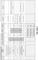
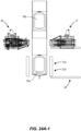
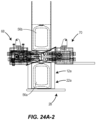
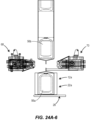
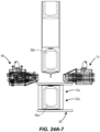
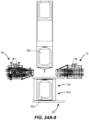
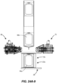
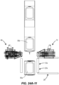
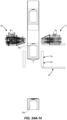
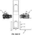
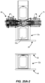
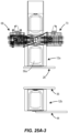
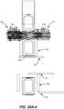
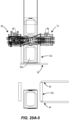
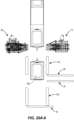
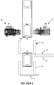
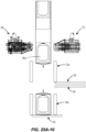
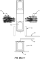
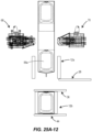
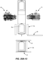
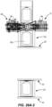
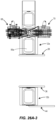
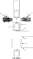
- Figures 24-26 illustrate graphical flow charts of various methods of forming a package using embodiments of the apparatus 10 disclosed herein.
- the apparatus 10 can be provided on a frame assembly that is portable, allowing the apparatus 10 to be moved into and out of configuration with the conventional packaging machine, which may include a forming tube or a portion of a forming tube.
- the frame assembly and/or components of the apparatus 10 can be adjustable to accommodate different packaging machine configurations and heights.
- the apparatus 10 may be a permanent and non-adjustable component of the packaging machine.
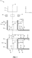
- the apparatus 10 will use at least one folding bar (e.g., a first downstream folding bar 28, a first upstream folding bar 36, and/or a second downstream folding bar 44 illustrated in Figure 1 ) to apply pressure to a package (e.g., the package 56a of Figure 4A ) on or adjacent to one or more transverse seals (e.g., a first transverse seal 66 and/or a second transverse seal 67 as illustrated in Figure 4A ).
- the first transverse seal 66 is also referred to herein as the leading seal
- the second transverse seal 67 is also referred to herein as the trailing seal.
- first transverse seal 66a and/or the second transverse seal 67a This pressure folds the first transverse seal 66a and/or the second transverse seal 67a towards the respective panel from which it extends and can attached the seal 66a, 67a to the material of the corresponding panel of the first package 56a. Additionally, residual heat can remain in the material of the first transverse seal 66a and/or the second transverse seal 67a resulting from the heat imparted to the material by first and second seal bars 68, 70 during the sealing of the first and/or second transverse seal 66, 67. This residual heat can aid in heat sealing the material of the seals 66, 67 to the material of the corresponding panel from which it extends during operation of the folding bars. In various embodiments, the apparatus can utilize multiple folding bars.
- the apparatus 10 can provide an efficient way to quickly transversely seal a plurality of packages while folding over and optionally sealing the transverse seals 66a, 67a to the body of the package 56a. Because the transverse seals 66a, 67a are folded over and, in some embodiments, secured to the body of the package 56a, the transverse seals 66a, 67a lie substantially flat or flat on-and not perpendicular or oblique to-the body of the package 56a. Consequently, the top and bottom transverse seals 66a, 67a are not damaged or deformed when being boxed for shipment and do not cause spacing issues while being boxed.
- an embodiment of the apparatus 10 for making a flexible package may include a retaining structure 12a that extends along the transport axis 14 from a first end 16a to a second end 18a opposite the first end 16a.
- the retaining structure 12a comprises two or more walls 20a that cooperate to form a lateral enclosure 22a, and each of the two or more walls 20a extend from the first end 16a to the second end 18a of the retaining structure 12a.
- At least a first one 24a of the two or more walls 20a displaces relative to a second one 26a of the two or more walls 20a.
- the retaining structure 12a can be provided as a first forming box having opposed opened ends that allow the film to be received into the structure from one end and the folding bar 22 to interact with the transverse seal at the opposed end.
- the retaining structure 12a can include a volume adjusting plate that actuates from one of the walls of the retaining structure in a direction perpendicular to the transport direct to define a pre-set internal volume of the package during gas filling and/or sealing of the second transverse seal.
- the apparatus 10 includes a first downstream folding bar 28 disposed downstream (i.e., in a direction along the transport path of the flexible material) of the retaining structure.
- a first downstream folding bar 28 disposed downstream (i.e., in a direction along the transport path of the flexible material) of the retaining structure.
- the first downstream folding bar 28 has a contact portion 30, and the first downstream folding bar 28 is displaceable between a first position 32 in which the contact portion 30 is disposed remote from the second end 18a of the retaining structure 12a and a second position 34 in which the contact portion 30 is disposed at or adjacent to the second end 18a of the retaining structure 12a.
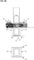
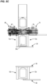
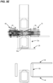
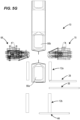
- the apparatus 10 also includes a second forming box 12b longitudinally-offset (i.e., offset along the longitudinal transport axis 14) from the retaining structure 12a and downstream of both the retaining structure 12a and the first downstream folding bar 28.
- the second forming box 12b extends along the transport axis 14 from a first end 16b to a second end 18b opposite the first end 16b.
- the second forming box 12b includes two or more walls 20b that cooperate to form a lateral enclosure 22b. In various embodiments, the second forming box 12b can restrain the package about the entire circumference of the package.
- the second forming box 12b can be sized to be about 70% to about 120%, about 80% to about 90%, about 80% to about 95%, about 70% to about 110%, about 80% to about 100%, and other suitable ranges therein, of the pre-determined internal volume of the package. As described in detail below, sizing of the second forming box 12b (and other forming box structures of various other embodiments) to tightly restrain the package to allow for only expansion of the film to the pre-determined internal volume can allow the internal pressure within the package to act against the force of the first upstream folding bar 36 when it actuates to fold the second transverse seal 67 over toward the respective panel of the package.
- the apparatus 10 further includes a first upstream folding bar 36 disposed upstream (i.e., in a direction opposite to the direction of the transport path of the flexible material) of the second forming box 12b and adjacent the first end 16b of the second forming box 12b.
- the first upstream folding bar 36 may have a contact portion 38 and may be displaceable between a first position 40 in which the contact portion 38 is disposed remote from the second forming box 12b and a second position 42 in which the contact portion 38 is disposed at or adjacent to the first end 16b of the second forming box 12b.
- the apparatus 10 additionally includes a second downstream folding bar 44 disposed downstream of the second forming box 12b and adjacent the second end 18b of the second forming box 12b.
- the second downstream folding bar 44 includes a contact portion 46 and is displaceable between a first position 48 in which the contact portion 46 is disposed remote from the second forming box 12b and a second position 50 in which the contact portion 46 is disposed at or adjacent to the second end 18b of the second forming box 12b.
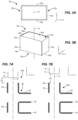
- the retaining structure 12a which is illustrated in Figure 3B , extends along the transport axis 14 from the first end 16a to the second end 18a opposite the first end 16a.
- the retaining structure 12a may have any suitable shape or combination of shapes.
- the retaining structure 12a may include two or more walls 20a that cooperate to form the lateral enclosure 22a, and the lateral enclosure 22a may be adapted to at least partially enclose a package 56, as illustrated in Figure 4A .
- the retaining structure 12a may include four walls-i.e., a first wall 52a, a second wall 53a, a third wall 54a, and a fourth wall 55a-that cooperate to form the lateral enclosure 22a, and the first wall 52a, the second wall 53a, the third wall 54a, and the fourth wall 55a may cooperate to completely surround a lateral or circumferential portion of the package 56.
- the first wall 52a, the second wall 53a, the third wall 54a, and the fourth wall 55a may all be planar or substantially planar and may be aligned with the transport axis 14.
- first wall 52a may be parallel to the second wall 53a and offset from the second wall 53a in a direction normal to the transport axis 14 and along the X-axis of the Reference Coordinate System of Figure 3B .
- the third wall 54a may extend from a first end portion of the first wall 52a and a first end portion of the second wall 53a and the fourth wall 55a may extend from a second end portion of the first wall 52a and a second end portion of the second wall 53a. So configured, the third wall 54a may be parallel to the fourth wall 55a and offset from the fourth wall 55a in a direction normal to the transport axis 14 and along the Y-axis of the Reference Coordinate System of Figure 3B .
- each of the first wall 52a, the second wall 53a, the third wall 54a, and the fourth wall 55a may form a top perimeter edge 58a at the first end 16a of the retaining structure 12a.
- the top perimeter edge 58a may be disposed in a plane normal to the transport axis 14 (i.e., a plane parallel to the X-Y plane of the Reference Coordinate System of Figure 3B ).
- each of the first wall 52a, the second wall 53a, the third wall 54a, and the fourth wall 55a may form a bottom perimeter edge 58 at the second end 18a of the retaining structure 12a.
- the bottom perimeter edge 60a may be disposed in a plane normal to the transport axis 14 (i.e., a plane parallel to the X-Y plane of the Reference Coordinate System of Figure 3B ) and may be longitudinally offset (i.e., offset in a direction along the transport axis 14) from the plane of the top perimeter edge 58a.
- first wall 52a may displace relative to the second wall 53a (or to the transport axis 14)
- the second wall 53a may displace relative to the first wall 53a (or to the transport axis 14)
- both the first wall 52a and the second wall 53a may displace relative to each other (or to the transport axis 14).
- the first wall 52a and/or the second wall 53a may displace from a first position 62a (an example of which illustrated in Figure 4A ) to a second position 64a (an example of which is illustrated in Figure 4B ).
- the first wall 52a and the second wall 53a may each be a first transverse distance D1 (i.e., a distance normal to the transport axis 14) from the transport axis 14.
- the first wall 52a and the second wall 53a may be parallel or may be disposed at an angle ( e.g ., an oblique angle) to each other.
- the first wall 52a and the second wall 53a may each be a second transverse distance D2 from the transport axis 14, and the second transverse D2 distance may be greater than the first transverse distance D1.
- the first wall 52a and the second wall 53a may be parallel or may be disposed at an angle ( e.g ., an oblique angle) to each other.
- At least one of the two or more walls 20a contacts a portion of the package 56, such as a circumferential and/or lateral portion of the package 56.
- at least two of the two or more walls 20a e.g. , each of the first wall 52a and the second wall 53a
- contact corresponding portions of the package 56 such as a first circumferential and/or lateral portion of the package 56 and a second circumferential and/or lateral portion of the package 56.
- each of the first wall 52a, the second wall 53a, the third wall 54a, and the fourth wall 55a contacts corresponding portions of the package 56, such as a first circumferential and/or lateral portion of the package 56, a second circumferential and/or lateral portion of the package 56, a third circumferential and/or lateral portion of the package 56, and a fourth circumferential and/or lateral portion of the package 56, respectively.
- At least one of the two or more walls 20a transversely displaces away from the transport axis 14 (e.g., in a direction parallel to the X-axis or Y-axis of the Reference Coordinate System of Figure 3B ), and in the second position 64a, the at least one of the two or more walls 20a may displace out of contact with ( i.e. , disengages) the portion of the package 56, such as the circumferential and/or lateral portion of the package 56.
- At least two of the two or more walls 20a (e.g ., each of the first wall 52a and the second wall 53a) transversely displaces away from the transport axis 14, and in the second position 64a, the at least two of the two or more walls 20a may displaces out of contact with ( i.e ., disengages) the corresponding portions of the package 56, such as the first circumferential and/or lateral portion of the package 56 and the second circumferential and/or lateral portion of the package 56.
- each of the first wall 52a, the second wall 53a, the third wall 54a, and the fourth wall 55a transversely displaces away from the transport axis 14, and each of the first wall 52a, the second wall 53a, the third wall 54a, and the fourth wall 55a may displace out of contact with ( i.e. , disengage) the corresponding portions of the package 56, such as a first circumferential and/or lateral portion of the package 56, a second circumferential and/or lateral portion of the package 56, a third circumferential and/or lateral portion of the package 56, and a fourth circumferential and/or lateral portion of the package 56, respectively.
- the retaining structure 12a may also translate longitudinally ( i.e ., along the transport axis 14) relative to a second end 72 of a forming tube 74 and/or to the second forming box 12b.
- the retaining structure 12a may longitudinally translate towards or away from the second end 72 of the forming tube 74 and/or towards or away from ( e.g ., upstream or downstream of) the second forming box 12b.
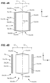
- the first end 16a of the retaining structure 12a may be a first longitudinal distance D3 from the second end 72 of the forming tube 74 (or a transverse fixed reference axis upstream of the retaining structure 12a) in a first position 94a, as illustrated in Figure 7A .
- the first end 16a of the retaining structure 12a may be a second longitudinal distance D4 from the second end 72 of the forming tube 74 (or the transverse fixed reference axis upstream of the retaining structure 12a), and the second longitudinal distance D4 may be greater than the first longitudinal distance D3.
- the at least one of the two or more walls 20a may be a single, unitary part or may be a segmented wall comprising two or more component parts. More specifically, all of the first wall 52a, the second wall 53a, the third wall 54a, and the fourth wall 55a may be a single unitary part, or at least one of the first wall 52a, the second wall 53a, the third wall 54a, and the fourth wall 55a may be a segmented wall comprising two or more component parts.
- a first portion of the third wall 54a was coupled to the first wall 52a and a second portion of the third wall 54a was coupled to the second wall 53a. So configured, the first portion of the third wall 54a and the first wall 52a rotationally displaces from the first position 62a to and from the second position 64a and the second portion of the third wall 54a and the second wall 53a rotationally displaces from the first position 62a to and from the second position 64a.
- the apparatus 10 further includes the first downstream folding bar 28 disposed downstream of the retaining structure 12a, and the first downstream folding bar 28 may be elongated in a transverse direction.
- the first downstream folding bar 28 may have the contact portion 30 that is adapted to contact an upper or lower (relative to the circumferential and/or lateral) portion of the package 56.
- the contact portion 30 may be adapted to contact at least a portion of a transverse seal (or flap) formed on an upper or lower portion of the package 56.
- the first downstream folding bar 28 may be transversely displaceable between a first position 32 (illustrated in solid lines in Figures 1 ) and a second position 34 (illustrated in dashed lines in Figure 1 ).
- the contact portion 30 In the first position 32, the contact portion 30 is disposed remote from the second end 18a of the retaining structure 12a. More specifically, in the first position 32, a reference point 83 of the contact portion 30 may not intersect the transport axis 14 or may be a first transverse distance 84 from the transport axis 14.
- the contact portion 30 is disposed at or adjacent to the second end 18a of the retaining structure 12a such that the contact portion 30 (or the reference point 83 of the contact portion 30) contacts or engages the portion of the transverse seal (or flap) formed on an upper or lower portion of the package 56.
- the contact portion 30 contacts or engages a portion of a first transverse seal 66 (or flap) formed on a lower portion of the package 56.
- the reference point 83 of the contact portion 30 may be a second transverse distance 85 from the transport axis 14 that is less than the first transverse distance 84. If the reference point 83 of the contact portion 30 intersects or is aligned with the transport axis 14 in the second position 34, the second transverse distance 85 from the transport axis 14 may be zero.
- the first downstream folding bar 28 may extend transversely across the entire second end 18a of the retaining structure 12a when in the second position 34. In other embodiments, the first downstream folding bar 28 may extend transversely across a portion of the second end 18a of the retaining structure 12a.
- the first downstream folding bar 28 may extend from the first position 32 to the second position 34 (and vice versa) in any manner known in the art.
- the first downstream folding bar 28 may be planar or substantially planar and may linearly translate from the first position 32 to the second position 34 (and vice versa) within a plane normal to the transport axis 14. In other embodiments, the first downstream folding bar 28 may rotate from the first position 32 to the second position 34 (and vice versa) within a plane normal to the transport axis 14.
- the first downstream folding bar 28 may include two or more plates (not shown) having transverse edges that are hinged such that in the second position 34, the two or more plates cooperate to form a planar shape and in the first position 32, adjacent plates of the two or more plates rotate about the hinged transverse edges to form an angle of less than 180 degrees (e.g., 45 degrees).
- the first downstream folding bar 28 may also longitudinally translate relative to the second end 72 of a forming tube 74 and/or to the second forming box 12b.
- the first downstream folding bar 28 may longitudinally translate longitudinally towards or away from the second end 72 of the forming tube 74 and/or towards or way from the second forming box 12b.
- the first downstream folding bar 28 may be longitudinally fixed relative to the retaining structure 12a such that the first downstream folding bar 28 longitudinally translates from a first position 98 (when, e.g., the retaining structure 12a is in the first position 94a) illustrated in Figure 7A and a second position 99 (when, e.g., the retaining structure 12a is in the second position 96a) illustrated in Figure 7B .
- the first downstream folding bar 28 may longitudinally translate towards or away from the retaining structure 12a.
- the apparatus 10 may include first and second seal bars 68, 70, and the first and second seal bars 68, 70 are disposed upstream of the first end 16a of the retaining structure 12a.
- the first and second seal bars 68, 70 may also be disposed downstream of the second end 72 of the forming tube 74 such that the first and second seal bars 68, 70 are disposed between the second end 72 of the forming tube 74 and the first end 16a of the retaining structure 12a.
- the forming tube 74 may extend along the transport axis 14, and film used to form one of a plurality of packages (e.g., the package 56) may be shaped around the forming tube 74 in known manner.
- product that is to be enclosed in the package 56 may be transported from a hopper (not shown) through an interior passageway through the forming tube 74 and out of the second end in a known manner.
- the first and second seal bars 68, 70 may each be elongated and extend along a linear axis that may extend in a transverse direction ( e.g. , along the Y-axis of the Reference Coordinate System provided in Figure 1 ) and each of the first and second seal bars 68, 70 may be parallel.
- Each of the first and second seal bars 68, 70 may be disposed on opposing sides of the transport axis 14 and each of the first and second seal bars 68, 70 may translate in a transverse direction ( e.g. , in a direction parallel to the X-axis of the Reference Coordinate System provided in Figure 1 ) towards the transport axis 14.
- the first and second seal bars 68, 70 may cooperate to form the transverse seal (or flap) formed on an upper or lower portion of the package 56.
- the first and second seal bars 68, 70 may cooperate to form the first transverse seal 66 (or flap) formed on a lower portion of the package 56.
- the first and second seal bars 68, 70 may also cooperate to form a second transverse seal 67 (or flap) formed on an upper portion of the package 56.
- the first and second seal bars 68, 70 may form the transverse seal (e.g., the first and/or second transverse seal 66, 67) in any known manner, such as by heat sealing.
- the first and second seal bars 68, 70 may also longitudinally translate with a package 56 (as illustrated in Figures 5B to 5E , for example) while forming the first and/or second transverse seal 66, 67.
- the first and second seal bars 68, 70 may translate longitudinally upwards or downwards relative to the second end 72 of the forming tube 74 and/or to the first end 16a of the retaining structure 12a.
- the apparatus 10 may also include the second forming box 12b that extends along the transport axis 14 from the first end 16b to the second end 18b opposite the first end 16b.
- the second forming box 12b may have any suitable shape or combination of shapes, and the second forming box 12b may be identical physically and functionally to the retaining structure 12a.
- the second forming box 12b may include two or more walls 20b that cooperate to form the lateral enclosure 22b, and the lateral enclosure 22b may be adapted to at least partially enclose the package 56.
- the second forming box 12b may include four walls- i.e ., a first wall 52b, a second wall 53b, a third wall 54b, and a fourth wall 55b-that cooperate to form the lateral enclosure 22b, and the first wall 52b, the second wall 53b, the third wall 54b, and the fourth wall 55b may cooperate to completely surround a lateral or circumferential portion of the package 56.
- the first wall 52b, the second wall 53b, the third wall 54a, and the fourth wall 55b may all be planar or substantially planar and may be aligned with the transport axis 14.
- first wall 52b may be parallel to the second wall 53b and offset from the second wall 53b in a direction normal to the transport axis 14 and along the X-axis of the Reference Coordinate System of Figure 8B .
- the third wall 54b may extend from a first end portion of the first wall 52b and a first end portion of the second wall 53b and the fourth wall 55b may extend from a second end portion of the first wall 52b and a second end portion of the second wall 53b. So configured, the third wall 54b may be parallel to the fourth wall 55b and offset from the fourth wall 55b in a direction normal to the transport axis 14 and along the Y-axis of the Reference Coordinate System of Figure 8B .
- each of the first wall 52b, the second wall 53b, the third wall 54b, and the fourth wall 55b may form a top perimeter edge 58b at the first end 16b of the second forming box 12b.
- the top perimeter edge 58b may be disposed in a plane normal to the transport axis 14 ( i.e., a plane parallel to the X-Y plane of the Reference Coordinate System of Figure 8B ).
- each of the first wall 52b, the second wall 53b, the third wall 54b, and the fourth wall 55ab may form a bottom perimeter edge 58b at the second end 18b of the second forming box 12b.
- the bottom perimeter edge 60b may be disposed in a plane normal to the transport axis 14 ( i.e., a plane parallel to the X-Y plane of the Reference Coordinate System of Figure 8B ) and may be longitudinally offset ( i.e. , offset in a direction along the transport axis 14) from the plane of the top perimeter edge 58b.
- first wall 52ba may displace relative to the second wall 53b
- the second wall 53b may displace relative to the first wall 53b
- both the first wall 52b and the second wall 53b may displace relative to each other (or to the transport axis 14).
- the first wall 52b and/or the second wall 53b may displace from a first position 62b (an example of which illustrated in Figure 4A ) to a second position 64b (an example of which is illustrated in Figure 4B ).
- the first wall 52b and the second wall 53b may each be a first transverse distance D1 (i.e., a distance normal to the transport axis 14) from the transport axis 14.
- the first wall 52b and the second wall 53b may be parallel or may be disposed at an angle ( e.g ., an oblique angle) to each other.
- the first wall 52b and the second wall 53b may each be a second transverse D2 distance from the transport axis 14, and the second transverse distance D2 may be greater than the first transverse distance D1.
- the first wall 52b and the second wall 53b can move symmetrically such that the first and second transverse distances D1, D2 are symmetrical about the transport axis 14.
- the first wall 52b and the second wall 53b can move different distances such that the first and second transverse distances D1 and D2 are asymmetrical about the transport axis 14.
- only one of the walls can move while the other is stationary.
- the first wall 52b and the second wall 53b may be parallel or may be disposed at an angle ( e.g., an oblique angle) to each other.
- At least one of the two or more walls 20b contacts a portion of the package 56, such as a circumferential and/or lateral portion of the package 56.
- at least two of the two or more walls 20b e.g. , each of the first wall 52b and the second wall 53b
- contact corresponding portions of the package 56 such as a first circumferential and/or lateral portion of the package 56 and a second circumferential and/or lateral portion of the package 56.
- each of the first wall 52b, the second wall 53b, the third wall 54b, and the fourth wall 55b contacts corresponding portions of the package 56, such as a first circumferential and/or lateral portion of the package 56, a second circumferential and/or lateral portion of the package 56, a third circumferential and/or lateral portion of the package 56, and a fourth circumferential and/or lateral portion of the package 56, respectively.
- At least one of the two or more walls 20b transversely displaces away from the transport axis 14 (e.g., in a direction parallel to the X-axis or Y-axis of the Reference Coordinate System of Figure 2A), and in the second position 64b, the at least one of the two or more walls 20b may displace out of contact with ( i.e ., disengages) the portion of the package 56, such as the circumferential and/or lateral portion of the package 56.
- At least two of the two or more walls 20b (e.g ., each of the first wall 52b and the second wall 53b) transversely displaces away from the transport axis 14, and in the second position 64b, the at least two of the two or more walls 20b may displace out of contact with ( i.e ., disengages) the corresponding portions of the package 56, such as the first circumferential and/or lateral portion of the package 56 and the second circumferential and/or lateral portion of the package 56.
- each of the first wall 52b, the second wall 53b, the third wall 54b, and the fourth wall 55b transversely displaces away from the transport axis 14, and each of the first wall 52b, the second wall 53b, the third wall 54b, and the fourth wall 55b may displace out of contact with ( i.e ., disengage) the corresponding portions of the package 56, such as a first circumferential and/or lateral portion of the package 56, a second circumferential and/or lateral portion of the package 56, a third circumferential and/or lateral portion of the package 56, and a fourth circumferential and/or lateral portion of the package 56, respectively.
- the second forming box 12b may be longitudinally fixed relative to the second end 72 of a forming tube 74 and/or to the retaining structure 12a. However, as illustrated in Figures 9A and 9B , the second forming box 12b may translate longitudinally relative to the second end 72 of a forming tube 74 and/or to the retaining structure 12a. For example, the second forming box 12b may longitudinally translate towards or away from the second end 72 of the forming tube 74 and/or towards or away from the retaining structure 12a.
- the first end 16b of the second forming box 12b may be a first longitudinal distance D5 from the second end 72 of the forming tube 74 (or a transverse fixed reference axis upstream of the retaining structure 12a) in a first position 94b, as illustrated in Figure 9A .
- the first end 16a of the second forming box 12b may be a second longitudinal distance D6 from the second end 72 of the forming tube 74 (or the transverse fixed reference axis upstream of the retaining structure 12a), and the second longitudinal distance D6 may be greater than the first longitudinal distance D4.
- the at least one of the two or more walls 20b may be a single, unitary part or may be a segmented wall comprising two or more component parts. More specifically, all of the first wall 52b, the second wall 53b, the third wall 54b, and the fourth wall 55b may be a single unitary part, or at least one of the first wall 52b, the second wall 53b, the third wall 54b, and the fourth wall 55b may be a segmented wall comprising two or more component parts.
- a first portion of the third wall 54b was coupled to the first wall 52b and a second portion of the third wall 54b was coupled to the second wall 53b. So configured, the first portion of the third wall 54b and the first wall 52b rotationally or laterally displaces from the first position 62b to and from the second position 64b and the second portion of the third wall 54b and the second wall 53b rotationally or laterally displaces from the first position 62b to and from the second position 64b.
- the apparatus 10 further includes the first upstream folding bar 36 that may be identical in structure and function to the first downstream folding bar 28.
- the first upstream folding bar 36 may be disposed downstream of the first downstream folding bar 28 and may be upstream of the first end 16b of the second forming body 12b.
- the first upstream folding bar 36 may be elongated in a transverse direction.
- the first upstream folding bar 36 may have the contact portion 38 that is adapted to contact an upper or lower (relative to the circumferential and/or lateral) portion of the package 56.
- the contact portion 38 may be adapted to contact at least a portion of a transverse seal (or flap) formed on an upper or lower portion of the package 56.
- the first upstream folding bar 36 may be transversely displaceable between a first position 40 and a second position 42, as illustrated in Figures 1 .
- the contact portion 38 In the first position 40, the contact portion 38 is disposed remote from the first end 16b of the second forming box 12b. More specifically, in the first position 40, a reference point 86 of the contact portion 38 may not intersect the transport axis 14 or may be a first transverse distance 87 from the transport axis 14.
- the contact portion 38 is disposed at or adjacent to the first end 16b of the second forming box 12b such that the contact portion 38 (or the reference point 86 of the contact portion 38) contacts or engages the portion of the transverse seal (or flap) formed on an upper or lower portion of the package 56.
- the contact portion 38 contacts or engages a portion of the second transverse seal 67 (or flap) formed on an upper portion of the package 56.
- the reference point 86 of the contact portion 38 may be a second transverse distance 88 from the transport axis 14 that is less than the first transverse distance 87. If the reference point 86 of the contact portion 38 intersects or is aligned with the transport axis 14 in the second position 42, the second transverse distance 87 from the transport axis 14 may be zero.
- the first upstream folding bar 36 may extend transversely across the entire first end 16b of the second forming box 12b when in the second position 42. In other embodiments, the first upstream folding bar 36 may extend transversely across a portion of the first end 16b of the second forming box 12b.
- the first upstream folding bar 36 may extend from the first position 40 to the second position 42 (and vice versa) in any manner known in the art.
- the first upstream folding bar 36 may be planar or substantially planar and may linearly translate from the first position 40 to the second position 42 (and vice versa) within a plane normal to the transport axis 14.
- the first upstream folding bar 36 may rotate from the first position 40 to the second position 42 (and vice versa) within a plane normal to the transport axis 14.
- the first upstream folding bar 36 may include two or more plates having transverse edges that are hinged such that in the second position 42, the two or more plates cooperate to form a planar shape and in the first position 40, adjacent plates of the two or more plates rotate about the hinged transverse edges to form an angle of less than 180 degrees (e.g., 45 degrees).
- the first downstream folding bar 36 may also longitudinally translate relative to the second end 72 of a forming tube 74 and/or to the retaining structure 12a and/or the second forming box 12b.
- the first downstream folding bar 36 may longitudinally translate longitudinally towards or away from the second end 72 of the forming tube 74 and/or towards or away from the retaining structure 12a and/or the second forming box 12b.
- a portion of the first downstream folding bar 36 may be a first longitudinal distance D7 from the second end 72 of the forming tube 74 (or a transverse fixed reference axis upstream of the retaining structure 12a) in a first position 100, as illustrated in Figure 10A .
- a portion of the first downstream folding bar 36 may be a second longitudinal distance D8 from the second end 72 of the forming tube 74 (or the transverse fixed reference axis upstream of the retaining structure 12a), and the second distance D8 may be less than the first distance D7.
- the apparatus 10 further includes the second downstream folding bar 44 that may be identical in structure and function to the first downstream folding bar 28 and/or the first upstream folding bar 36.
- the second downstream folding bar 44 may be disposed downstream of the second end 18b of the second forming body 12b.
- the second downstream folding bar 44 may be elongated in a transverse direction.
- the second downstream folding bar 44 may have the contact portion 46 that is adapted to contact an upper or lower (relative to the circumferential and/or lateral) portion of the package 56.
- the contact portion 46 may be adapted to contact at least a portion of a transverse seal (or flap) formed on an upper or lower portion of the package 56.
- the second downstream folding bar 44 may be transversely displaceable between a first position 48 and a second position 50, illustrated in Figure 1 .
- the contact portion 46 In the first position 48, the contact portion 46 is disposed remote from the second end 18b of the second forming box 12b. More specifically, in the first position 48, a reference point 89 of the contact portion 46 may not intersect the transport axis 14 or may be a first transverse distance 90 from the transport axis 14.
- the contact portion 46 is disposed at or adjacent to the second end 18b of the second forming box 12b such that the contact portion 46 (or the reference point 89 of the contact portion 46) contacts or engages the portion of the transverse seal (or flap) formed on an upper or lower portion of the package 56.
- the contact portion 46 contacts or engages a portion of the first transverse seal 66 (or flap) formed on a lower portion of the package 56.
- the reference point 89 of the contact portion 46 may be a second transverse distance 91 from the transport axis 14 that is less than the first transverse distance 90. If the reference point 89 of the contact portion 46 intersects or is aligned with the transport axis 14 in the second position 50, the second transverse distance 91 from the transport axis 14 may be zero.
- the second downstream folding bar 44 may extend transversely across the entire second end 18b of the second forming box 12b when in the second position 50. In other embodiments, the second downstream folding bar 44 may extend transversely across a portion of the second end 18b of the second forming box 12b.
- the second downstream folding bar 44 may extend from the first position 48 to the second position 50 (and vice versa) in any manner known in the art.
- the second downstream folding bar 44 may be planar or substantially planar and may linearly translate from the first position 48 to the second position 50 (and vice versa) within a plane normal to the transport axis 14. In other embodiments, the second downstream folding bar 44 rotate from the first position 48 to the second position 50 (and vice versa) within a plane normal to the transport axis 14.
- the second downstream folding bar 44 may include two or more plates having transverse edges that are hinged such that in the second position 50, the two or more plates cooperate to form a planar shape and in the first position 48, adjacent plates of the two or more plates rotate about the hinged transverse edges to form an angle of less than 180 degrees (e.g., 45 degrees).
- the second downstream folding bar 44 may also longitudinally translate relative to the second end 72 of a forming tube 74 and/or to the retaining structure 12a and/or to the second forming box 12b.
- the second downstream folding bar 44 may longitudinally translate longitudinally towards or away from the second end 72 of the forming tube 74 and/or towards or away from the retaining structure 12a.
- the second downstream folding bar 44 may be longitudinally fixed relative to the second forming box 12b such that the second downstream folding bar 44 longitudinally translates from a first position 102 (when, e.g., the second forming box 12b is in the first position 94b) illustrated in Figure 9A and a second position 103 (when, e.g., the second forming box 12b is in the second position 96b) illustrated in Figure 9B .
- the first downstream folding bar 28 may longitudinally translate towards or away from the second forming box 12b.
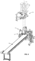
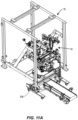
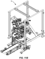
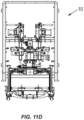
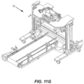
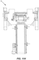
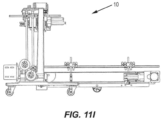
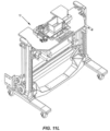
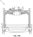
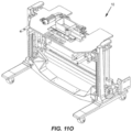
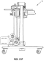
- the apparatus 10 can be provided on a frame assembly 76 illustrated in Figure 11A that is portable, allowing the apparatus 10 to be moved into and out of configuration with the conventional packaging machine104 illustrated in Figure 6 , which may include the forming tube 74 and other known forming features that cooperate to at least partially form the package 56 from a roll of film.
- the frame assembly 76 may include two or more rollers or casters 106 to facilitate mobility.
- Figures 11A to 11R illustrate the frame assembly and portions of the apparatus in absence of conventional packaging machine 104 elements such as the forming tube to illustrate the apparatus and portability thereof.
- the apparatus 10 may be used to form a plurality of packages 56, such as a first package 56a and a subsequently-formed second package 56b, which can be identical and are illustrated in Figures 4A and 4B .
- the first package 56a which may be formed in a known manner, may be at least partially disposed within the lateral enclosure 22a of the retaining structure 12a, as illustrated in Figures 2 , 4A, and 4B .
- the first package 56a may be at least partially formed and may be at least partially disposed within the lateral enclosure 22a of the retaining structure 12a.
- the partially-formed first package 56a may include the formed lateral or circumferential portion of the first package 56a (which may be formed and longitudinally-sealed sealed along the forming tube 74 in a known manner) as well as the first transverse seal 66a (or flap) formed on the lower portion of the package 56a, as illustrated in Figure 4A .
- the first transverse seal 66a (or flap) of the first package 56a may be formed by the first and second seal bars 68, 70.
- the first package 56a may extend along a first package axis 78a from a first end 80a to a second end 82a opposite to the first end 80a, and the first transverse seal 66a (or flap) may be disposed at or adjacent to the second end 82a.
- the second end 82a of the first package 56a may be adjacent to the second end 18a of the retaining structure 12a.
- the first package axis 78a may be parallel to or aligned with the transport axis 14.
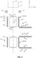
- the first downstream folding bar 28 may be displaced in a transverse direction (i.e., normal to the transport axis 14) from the first position 32 in which the contact portion 30 of the first downstream folding bar 28 (or in which the reference point 83 of the contact portion 30 of the first downstream folding bar 28) is the first transverse distance 84 from the transport axis 14 to the second position 34 in which the contact surface 30 of the first downstream folding bar 28 (or in which the reference point 83 of contact portion 30 of the first downstream folding bar 28) is the second transverse distance 85 from the transport axis 14 and may be adjacent to the second end 18a of the retaining structure 12a, as illustrated in Figures 5A and 5B .
- the contact portion 30 (at or adjacent to the reference point 83) applies pressure to the bottom flap 66a disposed at the second end of the first package.
- This pressure in conjunction with residual heat in the material of the first transverse seal 66 transferred by the first and second seal bars 68, 70, folds the seal over and seals the first transverse seal 66 to the material of the lower portion of the first package 56a.
- At least one of the two or more walls 20a that cooperate to form the lateral enclosure 22a of the retaining structure 12a displaces towards the transport axis 14 such that the at least one of the two or more walls 20 contacts a lateral portion of the first package 56a, as illustrated in Figures 5A and 5B .
- at least two of the two or more walls 20a e.g., each of the first wall 52a and the second wall 53a
- contact corresponding portions of the package 56a such as a first circumferential and/or lateral portion of the package 56 and a second circumferential and/or lateral portion of the package 56.
- each of the first wall 52a, the second wall 53a, the third wall 54a, and the fourth wall 55a contacts corresponding portions of the package 56, such as a first circumferential and/or lateral portion of the package 56, a second circumferential and/or lateral portion of the package 56, a third circumferential and/or lateral portion of the package 56, and a fourth circumferential and/or lateral portion of the package 56, respectively.
- each of the first seal bar 68 and the second seal bar 70 displaces towards the transport axis 14 to seal a portion of the first end 80 of the first package 56a to form the second transverse seal 67 (i.e., the top flap) formed on the upper portion of the first package 56a, as illustrated in Figures 5A and 5B .
- the first seal bar 68 and the second seal bar 70 may then longitudinally displace downstream while sealing the portion of the first end 80 of the first package 56a, as illustrated in Figures 5B to 5E .
- the first seal bar 68 and the second seal bar 70 may then displace away from the transport axis 14, as illustrated in Figures 5E and 5F .
- a cutting operation may transversely cut a transverse portion of the second transverse seal 67a to form a separate and fully-formed first package 56a.
- the cutting operation may occur as, after, or before the first seal bar 68 and the second seal bar 70 displace towards the transport axis 14 (or as, after, or before the first seal bar 68 and the second seal bar 70 form the second transverse seal 67a.
- the first folding box 12a and the first downstream folding bar 28 may longitudinally displace upstream to properly align the first package 56a, as illustrated in Figures 5A and 5B . While the first seal bar 68 and the second seal bar 70 form the second transverse seal 67 and longitudinally translate downstream, the first folding box 12a and the first downstream folding bar 28 may longitudinally displace downstream at the same rate of speed as the first seal bar 68 and the second seal bar 70, as illustrated in Figures 5B to 5E .
- the first downstream folding bar 28 may transversely displace (or may begin to displace) from the second position 34 to the first position 32.
- the first package 56a may displace or begin to displace (under the influence of gravity, and optionally through one or more guides, which are not shown) towards the second folding box 12b.
- the first upstream folding bar 36 may be in the second position 42 (or may displace from the first position 40 to the second position 42), as illustrated in Figures 5A to 5C and 5J to 5L .
- the second downstream folding bar 44 may be in the second position 50 (or may displace from the first position 48 to the second position 50), as illustrated in Figures 5B to 5C and 5G to 5M.
- At least one of the two or more walls 20b that cooperate to form the lateral enclosure 22b of the second forming box 12b may displace away from the transport axis 14 such that the at least one of the two or more walls 20b are adapted to receive the first package 56a, as Illustrated in Figure 5H .
- at least two of the two or more walls 20a displace away from the transport axis 14.
- each of the first wall 52a, the second wall 53a, the third wall 54a, and the fourth wall 55a displaces away from the transport axis 14.
- the first package 54 may then longitudinally translate downstream such that the first package 56a is at least partially disposed within the lateral enclosure 22b of the second forming box 12b, as illustrated in Figures 5G to 5J .
- the second end 82 of the first package 56a engages the contact portion 46 of the second downstream folding bar 44 (which is in the second position 50)
- at least one of the two or more walls 20b that cooperate to form the lateral enclosure 22b of the second forming box 12b may displace towards the transport axis 14 such that the at least one of the two or more walls 20b contacts a lateral portion of the first package 56a, as illustrated in Figure 5J and 5K .
- At least two of the two or more walls 20b contact corresponding portions of the first package 56a, such as a first circumferential and/or lateral portion of the first package 56a and a second circumferential and/or lateral portion of the first package 56a.
- each of the first wall 52b, the second wall 53b, the third wall 54b, and the fourth wall 55b contacts corresponding portions of the first package 56a, such as a first circumferential and/or lateral portion of the first package 56a, a second circumferential and/or lateral portion of the first package 56a, a third circumferential and/or lateral portion of the first package 56a, and a fourth circumferential and/or lateral portion of the first package 56a, respectively.
- the first upstream folding bar 36 may be displaced from the first position 40 to the second position 42 in which the contact surface 38 of the first upstream folding bar 36 (or in which the reference point 86 of the contact portion 38 of the first upstream folding bar 36) may be adjacent to the first end 16b of the second forming box 12b.
- the first upstream folding bar 36 may also longitudinally translate downstream (from the second position 101 to the first position 100 of Figure 10A and 10B ) after or as the first upstream folding bar 36 is displaced from the first position 40 to the second position 42, as illustrated in Figures 5K and 5L .
- the contact surface 38 of the first upstream folding bar 36 longitudinally travels to come into contact with the top flap 67a disposed at the first end 80a of the first package 56a.
- the contact portion 38 applies pressure to the top flap 67a disposed at the first end 80a of the first package 56a. This pressure, in conjunction with residual heat in the material of the second transverse seal 67 transferred by the first and second seal bars 68, 70, folds the seal over and attaches the second transverse seal 67 to the material of the upper portion of the first package 56a.
- the second downstream folding bar 44 may be in the second position 50, in which the contact portion 46 of the second downstream folding bar 44 (or in which the reference point 89 of contact portion 46) is the second transverse distance 90 from the transport axis 14 and may be adjacent to the second end 18b of the second forming box 12b.
- the contact portion 46 applies pressure to the bottom flap 66a disposed at the second end 82 of the first package 56a, which can aid in further setting a crease in the folded second transverse seal and in various embodiment setting a heat seal between the flexible material of the corresponding panel and the second transverse seal imparted when the first downstream folding bar 28 folds the second transverse seal over.
- the second downstream folding bar 44 also supports the weight of the package during actuation of the first upstream folding bar 36.
- the first upstream folding bar 36 actuates to a second position to engage the first transverse seal and apply a pressure to the package.
- This pressure in conjunction with residual heat in the material of the first transverse seal 66 transferred by the first and second seal bars 68, 70, folds the seal 66 over toward the panel from which it extends and, in some embodiments, attaches the first transverse seal 66 to the material of the lower portion of the first package 56a.
- the second downstream folding bar 44 After the second downstream folding bar 44 is in the second position 50 and applies pressure to the bottom flap 66 disposed at the second end 82 of the first package 56a, the second downstream folding bar 44 then translates to the first position 48, as illustrated in 5B to 5D.
- the first package 56a may displace or begin to displace (under the influence of gravity, and optionally through one or more guides, which are not shown) towards a conveyor 108 (illustrated in Figure 6 ) or other take-away device for further processing or packaging.
- the first seal bar 68 and the second seal bar 70 may form the first transverse seal 66b of the second package 56b, as illustrated in Figures 5E and 5F .
- the first downstream folding bar 28 may translate (or may begin to translate) from the first position 32 to the second position 34, as illustrated in Figures 5A and 5B .
- the fully-formed (or at least partially-formed) second package 56b may be at least partially disposed within the lateral enclosure 22a of the retaining structure 12a, as illustrated in Figure 5J to 5M .
- the partially-formed second package 56b may include the formed lateral or circumferential portion of the second package 56b (which may be formed and longitudinally sealed along the forming tube 74 in a known manner) as well as the first transverse seal 66b (or flap) formed on the lower portion of the second package 56b.
- the first transverse seal 66b (or flap) of the second package 56b may be formed by the first and second seal bars 68, 70.
- the second package 56b may extend along a first package axis 78 from a first end 80 to a second end 82 opposite to the first end 80, and the first transverse seal 66 (or flap) may be disposed at or adjacent to the second end 82.
- the second end 82 of the second package 56b may be adjacent to the second end 18a of the retaining structure 12a.
- the package axis 78 of the second package 56b may be parallel to or aligned with the transport axis 14.
- the second package 56b Prior to or as the second package 56b may be at least partially disposed within the lateral enclosure 22a of the retaining structure 12a, at least one of the two or more walls 20a that cooperate to form the lateral enclosure 22a of the retaining structure 12a displaces away from the transport axis 14 as previously described and as illustrated with reference to the first package 56a in Figures 5F and 5G .
- the first downstream folding bar 28 may subsequently transversely displace from the first position 32 to the second position 34 (as previously described and as illustrated with reference to the first package 56a Figures 5A and 5B ).
- At least one of the two or more walls 20a that cooperate to form the lateral enclosure 22a of the retaining structure 12a displaces towards the transport axis 14 such that the at least one of the two or more walls 20 contacts a lateral portion of the second package 56b (in a manner substantially identical to the first package 56a illustrated in Figures 5A and 5B ).
- At least two of the two or more walls 20a contact corresponding portions of the second package 56b, such as a first circumferential and/or lateral portion of the second package 56b and a second circumferential and/or lateral portion of the second package 56b.
- each of the first wall 52a, the second wall 53a, the third wall 54a, and the fourth wall 55a contacts corresponding portions of the second package 56b, such as a first circumferential and/or lateral portion of the second package 56b, a second circumferential and/or lateral portion of the second package 56b, a third circumferential and/or lateral portion of the package 56, and a fourth circumferential and/or lateral portion of the package 56, respectively.
- each of the first seal bar 68 and the second seal bar 70 displaces towards the transport axis 14 to seal a portion of the first end 80 of the second package 56b to form the second transverse seal 67b (i.e., the top flap) formed on the upper portion of the second package 56b (in a manner identical to the first package 56a illustrated in Figures 5A and 5B ).
- the first seal bar 68 and the second seal bar 70 may then displace transversely away from the transport axis 14.
- the first folding box 12a and the first downstream folding bar 28 may longitudinally displace upstream to properly align the second package 56b (in a manner substantially identical to the first package 56a illustrated in Figures 5A and 5B ). While the first seal bar 68 and the second seal bar 70 form the second transverse seal 67b and longitudinally translate downstream, the first folding box 12a and the first downstream folding bar 28 may longitudinally displace downstream at the same rate of speed as the first seal bar 68 and the second seal bar 70, as illustrated in Figures 5B to 5E (in a manner identical to Figures 5B to 5E ).
- a cutting operation may transversely cut a transverse portion of the second transverse seal 67 to form a separate and fully-formed second package 56b, (in a manner identical to the first package 56a illustrated in Figure 5F ).
- the cutting operation may occur as, after, or before the first seal bar 68 and the second seal bar 70 displace towards the transport axis 14 (or as, after, or before the first seal bar 68 and the second seal bar 70 form the second transverse seal 67.
- the first upstream folding bar 36 may also longitudinally translate upstream (from the first position 100 to the second position 101 of Figure 10A and 10B ) after or as the first upstream folding bar 36 is displaced from the second position 42 to the first position 40, as illustrated in Figures 5E and 5F .
- the first downstream folding bar 28 may transversely displace (or may begin to displace) from the second position 34 to the first position 32, as illustrated in Figures 5E to 5G .
- the second package 56b may displace or begin to displace (under the influence of gravity, and optionally through one or more guides, which are not shown) towards the second folding box 12b (in a manner identical to the first package 56a illustrated in Figure 5G ).
- the process is substantially identical to that when the first package 56a was at least partially disposed within the lateral enclosure 22b of the second folding box 12b.
- the first seal bar 68 and the second seal bar 70 may form the first transverse seal 66 of a third package 56c.
- the first downstream folding bar 28 may translate (or may begin to translate from the first position 32 to the second position 34.
- the third package 56c may be at least partially disposed within the lateral enclosure 22a of the retaining structure 12a, and the process is that same for that of the second package 56b previously described.
- the apparatus 10 provides a high-velocity, mobile sealing machine that, as previously described, uses internal package pressure generated when the package is compressed by the folding bar, in conjunction with residual heat in the material of the first transverse seal 66a and/or the second transverse seal 67a transferred by, for example, the first and second seal bars 68, 70, to fold the seal over and optionally attach the first and second transverse seal 66a, 67a to the material of the lower and/or upper portions of the first package 56a.
- the transverse seals 66a, 67a are secured to the body of the package 56a, the transverse seals 66a, 67a lie substantially flat on-and not perpendicular or oblique to-the body of the package 56a, the top and bottom transverse seals 66a, 67a are not damaged or deformed when being boxed for shipment and do not cause spacing issues while being boxed.
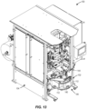
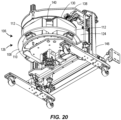
- the apparatus 100 for forming a package can include an interface 102 for generating a package having a cube or cuboid shape.
- the interface 102 can be configured to be used in connection with known packaging machines 104, including, for example, continuous motion vertical form fill seal packaging machines.
- a continuous motion vertical form fill seal packaging machine is Triangle Model XYT15 Vertical-Form-Fill Seal Bagging Machine.
- Such conventional bagging machines can conventionally produce, for example, gable top packages in which the bottom of the package is substantially flat.
- Such conventional packing machines are incapable of forming a cube or cuboid package.
- the interface 102 in accordance with embodiments of the description can be adapted to work in connection with such conventional machines to form cuboid packages.
- the conventional packaging machine can be modified in various embodiments to include a flap folding bar that actuates in two axes as opposed to a single axis as is conventional.
- a two axis motion such as described for the flap folding plate 130 of the interface, can be used for any of the described flap folding mechanisms of the packaging machines of the disclosure.
- the two axis motion can be controlled by an actuator that allows for independent control of the axes independently. This can allow for more flexibility when folding, which can improve the forming process and ultimately the package shape/structure.
- the interface 102 can be configured to reside beneath a conventional packaging machine 104, such that the package is seamlessly transferred from the conventional bagging machine to the interface.
- Embodiments in which the interface 102 is disposed beneath the packaging machine advantageously allow for the package to be dropped from the last stage of the packaging machine 104 into the interface 102 without the need for additional devices or transfer steps.
- other placements of the interface are contemplated herein, including arrangements in which conveyors or other transfer devices are utilized to transfer the package from the packaging machine to the interface.
- the interface can be made integral with the packaging machine to provide a single, non-separable packaging machine unit.
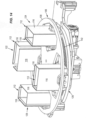
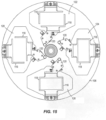
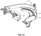
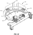
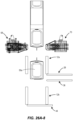
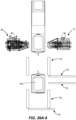
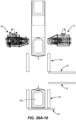
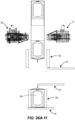
- the interface can include a rotary unit 106 that contains a plurality of forming boxes 112 disposed on a rotating axis to allow for translation in a generally circular motion of the forming boxes 112 through multiple stations of the interface 102.
- the forming boxes 112 can be attached to a rotating plate 108 that rotates the forming boxes in a circular motion. Any suitable means for rotating the plate 108 can be used.
- the rotating plate can be servo driven.
- the rotating plate 108 can include or be attached to a drive shaft that is connected to a servo motor gearbox for connection to the servo motor.
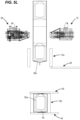
- the forming boxes 112 include first and second separable portions 116, 118.
- the portions 116, 118 can both be movable or only one of the portions can be moveable.
- the first portion 116 can be in a fixed position and rotate with the movement of the rotating plate 108, while the second portion is moveable into and out of engagement with the first portion 116 as well as rotating with the motion of the rotating plate 108.
- the second portion 116 of the forming boxes 112 can be connected to a cam assembly 120 that guides the second portion 116 in a secondary motion into and out of engagement with the first portion.
- the cam assembly 120 includes a cam follower that resides in a guide disposed beneath the rotating plate 108.
- the rotary unit 106 can include a dead plate 110 that resides beneath at least some of the forming boxes 112 and defines a bottom wall of the forming boxes 112.
- the dead plate 110 can include the guide 114 in which the cam follower resides, thereby defining the secondary motion of the forming boxes 112 around the rotary unit 106.
- the position of the second portion 118 is adjusted as the cam follower proceeds along the guide 114.
- the path of the guide 114 can be used to define the position of the second portion 118 of the forming box at a given station of the rotary unit 106.
- the package can be received in the forming box 112 from the packaging machine.
- the forming box 112 can be in a package receiving or open position in which the first and second portions are separated in order to allow the package to drop within the forming box 112.
- the second portion 118 can be guided into engagement with the first portion 116 to provide a tight fight around the package during subsequent processing.
- the second portion 118 can again be guided away from the first portion 116 to allow the forming box 112 to open and the package to exit the rotary unit 106.
- the forming box at the first station 122 is shown in an open position, while the forming box 112 at the second station 124 is shown in a closed position.
- the path of the guide 114 can be any suitable shape depending on the number of stations and the desired position of the forming box 112 at a given station.
- the forming box 112 portions 116, 118 can be actuated to any suitable number of positions. In one embodiment, the forming box is actuated between an open position and a closed position. In another embodiment, the forming box 112 portions 116, 118 can be actuated between a package receiving position in which the portions are slightly separated, a package retaining position, in which the portions are held together to tightly retain the package, and a package ejection position in which the portions are more widely separated than the packaging receiving position.
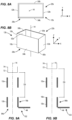
- the forming boxes 112 will have a size and shape corresponding to the package 200 to be formed.
- the forming boxes 112 can be readily removed from the rotary unit 106 to allow the forming boxes 112 to be easily changed for forming boxes of another size and/or shape to accommodate formation of a different sized or shaped package.
- the forming box will be sized to a have an internal volume that is 70% to 120% of the internal volume of the final cuboid package.
- Other suitable percentages include about 85% to about 100%, about 80% to about 90%, about 80% to about 95%, about 90% to about 100%, and about 80% to about 110%.
- the forming box 112 is sized to tightly retain the package, the forming box 112 reduces or prevents deformation of the flexible film beyond the predetermined internal package volume, thereby allowing the internal pressure within the package to act against the force of the flap folding plate, which can aid in achieving the cuboid shape of the package.
- the package can be configured to a have predetermined internal package volume during sealing of the package on the packaging machine. The internal package volume can be adjusted by the amount of product and/or the amount of gas allowed in or removed from the package just prior to sealing.
- the forming box 112 is also sized to account for the presence of quad seals on one or more panels of the package, as the presence of the quad seal can affect the width the forming box needed so not to deform or damage the one or more quad seals.
- the forming box 112 is also configured such that at least a portion of the panel of the package 200 having the trailing seal 210 will be disposed above the top edge of the walls of the forming box such that the trailing seal can be engaged by the folding plate or flap.
- the forming boxes 112 can include a volume adjuster that allows the internal volume of the box 112 to be adjusted during processing to accommodate packages that may be over or under filled with gas during the package sealing steps performed upstream of the interface 102.
- the packaging machine 104 can be adapted to include a volume-adjusting box that includes an actuating plate that squeezes the package to adjust the volume to the desired value just prior to sealing the package.
- the interface can be provided with the volume-adjusting box as a separate unit to be installed on the packaging machine.
- Providing the package with a sufficient internal volume (resulting from the presence of product and entrapped air or gas) within the package, as well as providing properly sized forming boxes aids in achieving well defined folds and creases in the package during processing on the interface, which in turn can allow for improved cuboid shaping and retention of the cuboid shape.
- Various conditions can be adjusted to control the internal package volume to achieve a targeted (predetermined) internal package volume.
- the volume-adjusting box can be used to remove gas from the package by slightly squeezing the package. This can be done with or without a gas flushing operation that adds gas to the package to further expand the package after filling with product. Gas flushing operations are known in the art and any known rates of fill, times of fill, and types of gasses can be used depending on the product contained therein.
- the speed of the seal jaws of the packaging machine can also be used to control the internal package volume. Actuation of the seal jaw more quickly can result in more gas being trapped within the package, while actuation of the seal jaw more slowly allows for the package to equilibrate and have less trapped gas.
- the forming box 112 can also include gas channels and/or other heating and cooling elements to facilitate folding and/or shaping of the package while the package resides in the forming box. Heating of portions of the forming box 112 can aid in forming defined edges of the package, while cooling can aid in setting any folds or seals in the package.
- the interface 102 will be made to an apparatus having four forming boxes 112 as illustrated in the figures. However, it is contemplated that additional or fewer forming boxes can be utilized.
- the number of forming boxes 112 included in the interface 102 can be determined based on a number of factors, including, but not limited to, the type and/or thickness of film used and ease of heat sealing and creasing, the desired speed of packages to be produced in a unit of time, the size of the interface and corresponding size of the packaging machine to which the interface is to be adapted, as well as the size of the forming boxes (which in turn relates to the size of the packages) and the number of secondary operations (such as heat setting edges) that are to be performed.
- the interface can include 2, 3, 4, 5, 6, 7, 8, 9, or 10 forming boxes.
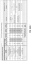
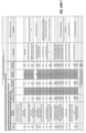
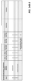
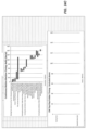
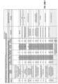
- FIGS 23A and 23B illustrate a timing chart for forming a package in accordance with an embodiment of the disclosure using the interfaces.
- the next forming box enters that station.
- the forming box can move continuously through the stations.
- the forming boxes can be arranged a fixed distance between each forming box or can be disposed at variable distances.
- the rotary unit can be provided in a racetrack configuration as opposed to the rotating disc as shown in the figures.
- motor driven chain drive or other actuating devices can be used to transport the forming boxes between the stations. Linear motor technology can allow for independent control of the distance between forming boxes and the timing of the forming boxes at a given station.
- the interface includes four stations and four forming boxes, with the forming boxes rotating in a clockwise direction. Counter-clockwise rotation is also contemplated herein. Further, as noted above, fewer or more forming boxes are also within the contemplation of the disclosure. Fewer or more stations are also contemplated herein.
- the rotary motion of the interface and processing of the package in multiple stations using multiple forming boxes allows for the interface to perform the cubing function with sufficient timing to define the edges of the package and, in particular, in part substantially flat panels to the sides of the package having the leading and trailing seals, while keeping up with the rate of the continuous motion packaging machine.
- the interface can be rotated at various speeds and configurations.
- the interface can run in an intermittent mode where the rotation is stopped for a duration of time before rotating the forming boxes to the next station. Stopping of the rotation can aid in transferring the package from the packaging machine to the forming box at the first station of the interface. This can be particularly useful when the package is transferred to the forming box at the first station by gravity after the seal of the package is cut from the continuous tube of flexible film in the packaging machine.
- the rotary unit 106 can be rotated continuously through the stations.
- the rotary unit 106 can be rotated at a continuous speed or a variable speed.
- the rotary unit 106 can slow as a forming box is approaching and or at the first station to receive a package and then speed up in the distance between stations. Any suitable rotating speed configuration can be used.
- a package is transferred from the packaging machine to the interface such that the panel of the package 200 having the trailing seal 210 is disposed near the top of the forming box 112 with the trailing seal 210 extending above the top edge of the forming box 112.
- the package is oriented such that the leading and trailing seals extend outwardly from a panel of the package in a direction that is parallel to the transport direction of the film.
- the packaging machine can include a flap folding apparatus for folding a leading seal of the package over such that it is disposed substantially in the plane of the panel of the package and, in some embodiments, attached to the respective panel of the package.
- the trailing seal 210 of the package 200 may remain substantially extended in an upright position after processing in the packaging machine.
- the packaging machine can form a combination leading and trailing seal in which a trailing seal of first package is formed in combination with the leading seal of the upstream package.
- the leading seal of the first package can be folded over by a flap folding bar that actuates across the package to engage the seal and fold it over to towards the panel of the package from which it extends.
- the combination leading and trailing seal can then be cut, which results in dropping of the package to the interface.
- the packaging machine can be modified to include a flap folding bar that can be raised in a coordinated manner with the operation of the seal jaws.
- Guide boxes or other guiding devices may be included on the interface and/or the packaging machine above the forming box at the first station 122 to facilitate transfer of the package in the proper orientation into the forming box 112.
- the package will reside with the folded leading seal disposed against a bottom wall of the forming box 112, if present, or on a dead plate and the trailing seal will be disposed in an upright position extending at least slightly above the top edge of the walls of the forming box 112.
- the forming box 112 can be disposed in the package receiving position to receive the package.
- the package receiving position can be a separation of first and second portions 116, 118 of the forming box as described in detail above.
- the forming box 112 can be rotated to the second station.
- the rotary unit can rotate the forming boxes continuously with continuous or variable speed, or intermittently where the forming boxes stop for a preset delay.
- the forming box is rotated to the second station 124, the package is engaged by a flap folding plate 130.
- the flap folding plate 130 actuates from a first (up) position (shown in Figure 18A ) downward towards and across the package to a second (down) position (shown in Figure 18B ) in which it engages and folds the trailing seal 210 over towards the panel of the package from which it extends and applies a force to the panel of the package to flatten the panel of the package.
- the flap folding plate 130 can actuate linearly perpendicular to the top of the forming box between the first and second positions.
- Various types of movement of the flap folding plate 130 can be accomplished in any embodiment of the disclosure.
- the flap folding plate 130 can be actuated in an angled linear motion as shown in the Figures 18A and 18B .
- the flap folding plate 130 can be coupled to an actuator or motor that allows for independent control of the flap folding plate 130 position in each of the two axis of movement.
- Other embodiments, include the flap folding plate 130 may be actuated along two axes by a pre-configured cam path or using a programmable path on independent axes.
- the force applied by the flap folding plate 130 also translates to an applied force against the panel of the package having the leading seal, forcing the panel against the bottom wall of the forming box 112, if present, or dead plate 110, which can aid in further defining a flat, cube-like shape to that panel of the package, as well.
- Figure 18B illustrates a gap between the top of the folding box 112 and the flap folding plate 130 when the flap folding plate is in the second, downward, position. The size of the gap can be varied depending on the package size and the internal volume of the package that is present to act against the force of the flap folding plate and aid in forming the side into a flat or flatter shape.
- the flap folding plate 130 can be disposed just above the top of the forming box 112 when it is in the second, downward, position.
- the flap folding plate 130 can be configured to begin actuating when the forming box 112 is at a pre-set distance from the first station 124, but prior to the forming box 112 reaching the second station 126.
- the flap folding plate 130 can begin to actuate when the forming box is 0° to 30° prior to the second station 124.
- the flap folding plate 130 can actuate when the forming box has positioned the package a sufficient distance towards the second station to allow the flap folding plate 130 to engage substantially all of the trailing seal substantially perpendicularly to the trailing seal.
- the flap folding plate 130 has actuated to the second (down) position in which it is disposed over the forming box and applies a pressure to the package to hold the trailing seal in the folded over position by the time the forming box reaches the second station.
- the flap folding plate 130 can actuate while the forming box 112 is stopped at the second station.
- the forming box is sized such that the internal volume with the flap folding bar 130 in the down position allows for the internal package to be slightly pressurized. This internal pressure presses against the film, opposing the force of the flap folding bar 130, which aids in defining the package to have the cuboid shape. Without sufficient internal pressure or a properly sized forming box, packages having less defined and sharp edges may be produced.
- the size of the forming box 112 can affect how the internal pressure against the force of the flap folding plate 130.
- the force of the flap folding plate 130 may cause the faces of the package to deform outwardly until they contact the walls of the forming box, thereby compressing the side panels having the leading and trailing seals towards each other rather than flattening against a resistant internal pressure.
- the forming box is properly size for a given predicted internal final package volume, but the package is under pressurized during sealing, there will be insufficient force to oppose the force of the flap folding plate to maintain and define the package shape.
- the under pressurized package may result in deformation of the package within the forming box, leading to a less defined cuboid shape, for example, a trapezoidal shape.
- the flap folding plate 130 can actuate using any known actuator or combinations of actuators. Further, as noted above, while the figures illustrate motion of the flap folding bar 130 in an angled linear motion, non-linear motion in two axes or single axis motion are contemplated herein. Referring to Figures 19A-19C , in one embodiment, the flap folding plate 130 can include a rail 132 disposed on the plate 130 and can be connected to an actuating arm 136, which in turn can be actuated by any suitable means such as motor or servo. A carriage assembly 134 or other rail connecting device can engage the rail 132.
- the carriage assembly or rail connecting device can be attached to the interface, for example, at a bracket 138, to retain the flap folding plate 130 in the proper position above the second station 124.
- Figure 19A shows the flap folding plate 130 in the first position in which it is disposed up and away from the forming box.
- Figure 19B shows the flap folding plate 130 in an intermediate position.
- Figure 19C shows the flap folding plate 130 in the second position in which it is positioned downward towards the forming box and engaging the package.
- the rail 132 can be angled such that the flap folding bar 130 is actuated both down and across the panel of the package exposed above the forming box 112.
- the rail can be angled about 15° to about 70°, about 20° to about 30°, about 20° to about 45°, or about 15° to about 30°, and other suitable ranges therein.
- the flap folding plate 130 can have a two-axis motion that is not constrained by a rail or guide angle as the embodiment shown in Figure 18A and 18B .
- Various known two-axis actuators can be used giving free motion in both axes.
- two-axis motion can be defined by a cam track that guides a cam follower and along with it the flap folding bar in a desired motion.
- Other embodiment can include systems for providing a programmable motion profile.
- the flap folding plate 130 can have any size or shape. In various embodiments, the flap folding plate is sized such that when actuated to the second (down) position, the plate covers the entire width of the forming box 112. Where the interface is contemplated for use with different sized forming boxes, the flap folding plate can be sized to have a width that is at least as wide as the widest forming box to be used. The flap folding plate 130 can have a length such that it is capable of engaging all or at least a portion of the package prior to the forming box being positioned in the second station 124. Additionally or alternatively, the flap folding plate 130 can have a length such that it is also capable of remaining in contact with the package when the forming box 112 leaves the second station. As illustrated in Figure 21 and discussed in detail below, the flap folding plate 130 can be sized so that it resides in the path between the second and third stations and is next to and optionally in contact with the holding plate 140 when in the second down position.
- the forming box transitions to a third station 126 that includes a holding plate 140 for providing additional dwell time to the folded trailing seal.
- the forming box can be transitioned to a final station (shown in the figures as a fourth station 128) for release of the package to a take-away device.
- the flap folding plate 130 moves back to the first position to reset for receipt of the next forming box into the second station 124.
- the package at the trailing seal and associated panel engages with a holding plate 140 disposed above the third station.
- the holding plate 140 can be configured to extend up to the end of the second station 124, such that there is substantially no gap between the flap folding plate 130 (when in the second position) and the holding plate 140.
- the holding plate can extend such that at least a portion of the holding plate covers substantially all of the top of the forming box when the forming box is 0° to about 70° after the end of the second station 124 or any point therebetween.
- FIG 21 is an isolated view of the flap folding plate 130 and holding plate 140 in accordance with an embodiment of the disclosure.
- the flap folding plate 130 and the holding plate 140 can be attached to a bracket 138.
- the flap folding plate 130 and holding plate 140 can be configured so they are directly adjacent each other and there is substantially no gap between the end of the flap folding plate 130 and the end of the holding plate 140.
- the transition from the flap folding plate 130 to the holding plate 140 can be disposed at the edge of the forming box located in the second station 124 or at a distance past the second station 124, between the second and third stations, 124, 126.
- the holding plate 140 can be in a stationary position at a height for engaging the package in the forming box as it rotates from the flap folding plate 130 to the holding plate 140.
- the holding plate 140 can actuate in a linear (up and down) position to engage the package as it rotates to a predetermined position.
- the holding plate 140 can actuate from a first (up) position to a second (down) position when the forming box is 0° to 70° past the end of the second station 124 and then actuate from the second (down) position to the first (up) position when the forming box is 0° to 70° past the end of the third station.
- the transition between the folding plate 130 and the holding plate 140 occurs at the edge of the forming box at the second station 124 so that the package transfers quickly to the stationary 140 and the flap folding plate 130 can be withdrawn to the first position as the forming box transitions out of the second station to reset for the next forming box.
- the holding plate 140 can also be disposed such that it is in line with the flap folding bar 130 when it is disposed in the second (downward) position and engaging the package. So configured, once the forming box begins to transition out of the second station, the package immediately or substantially immediately engages the holding plate 140. For example, in one embodiment, the package can be engaged with the flap folding plate 130 and the holding plate 140 at the same time.
- the holding plate 140 can also extend past the third station 126 through the transition between the third and fourth stations 126, 128 or even above the fourth station as well. In other embodiments, the holding plate 140 terminates at the third station or at a transition point between the third and fourth stations.
- the holding plate 140 applies continued dwell pressure to the panel of the package and the folded trailing seal.
- This added dwell time can allow for the additional time needed for attaching the trailing seal to the panel of the package or imparting a strong fold in the trailing seal so that it resides in the substantially the same plane as the panel of the package and does not unfold during use.
- any number of processes can be used including heat sealing and/or the application of an adhesive.
- the interface with the added dwell time provided by the holding plate 140 can allow for attachment of the trailing seal using the residual heat remaining in the trailing seal during the seal forming process to heat seal the trailing seal to the film at the panel of the package.
- the forming box 112 then transitions to the final (fourth) station 128 where the package is released from the forming box 112. While reference is made herein to a fourth station, it should be understood that the number of the stations will change depending on the number of stations included in the interface.
- the interface will include a package receiving station (first station 122 of the Figures), a flap folding station (second station 124 of the figures) and a final package release station (fourth station 126 of the figures).
- the interface can optionally include a dwell time station where a holding plate 140 applies pressure to the trailing seal after flap folding as added dwell time. Additional stations, such as edge heating stations, can also be included in the interface as desired.
- the forming box can open slightly to release the package.
- the forming box does not include a bottom wall and instead is positioned adjacent to a dead plate 110.
- the dead plate can be sized and shaped to be disposed in the first, second, and third stations, but not in the fourth station.
- the package drops through the opening in the bottom of the forming box onto a take away system, such as a conveyor.
- Figure 16 illustrates the dead plate 110 in isolation showing an embodiment in which the dead plate is shaped as a truncated disc.
- the truncation of the disc corresponds to the location of the fourth station 128, which allows the package to fall through the forming box 112 past the dead plate 110 and onto a take away system, such as a conveyor.
- a take away system such as a conveyor.
- the dead plate can be a complete disc having an aperture disposed in the location of the fourth station that is sized to allow the package to fall through the aperture to the take away system.
- Figure 12 illustrates an embodiment in which the package is released from the fourth station 128 onto a conveyor.
- the forming box can include a bottom wall that actuates out of position to provide an opening in the bottom of the forming box through which the package can drop.
- the forming box can actuate to an opening position in which the package can be ejected from a side of the forming box as opposed to through the bottom.
- the dead plate 110 and/or the holding plate 140 can include one or more groves 142 housing outlets of gas or air passageways to allow for heated and/or cooled air to be directed onto the package. While reference herein is made to air outlets and passages, it should be understood that other gasses can be suitably used and flowed through these structures as an alternative to air.
- the dead plate can direct heated air or other gas toward the panel of the package having the leading seal (residing at the bottom of the forming box) to aid in further defining the shape of the package at that end while it is constrained in the forming box.
- the heated air can be directed to the package for a first portion of the rotary cycle.
- the first portion can be, for example, through the first and second stations.
- the dead plate can then be configured to direct cooled air to set the panel of the package at the bottom of the forming box through a second portion of the rotary cycle, for example, through the transition of the forming box from the second to the fourth stations.
- the holding plate 140 can include grooves 142 and air passages to direct cooled or heated air to the trailing seal panel of the package.
- the holding plate 140 can direct heated air to the panel of the package with the trailing seal when the package initially transitions from the second station to the third station and then direct cooled air to the panel of the package when it is in the third station and through transition to the end of the holding plate 140. Any timing or configuration of cooled or heated air can be used in either the dead plate or the holding plate 140. It is also contemplated herein that no heating or cooling using air directed to the package is used.
- the interface can include an upper bracket 138 that may include a transition guide box 144 that guides the package from the packaging machine into the forming box at the first station.
- the holding plate 140 and the flap folding plate 130 can be attached to the bracket 138.
- the bracket 138 can be attached to a frame 146 of the interface.
- the frame can house the rotary unit 106 having rotating plate 108, the forming boxes 112, the dead plate 110, and various actuating mechanisms needed for rotation of the forming boxes 112 and/or the rotary plate 108.
- the bracket 138 can be adjustable on the frame 146 such that the position of the holding plate 140 and the flap folding plate 130 can be adjusted relative to the top of the forming boxes to accommodate changes in package and/or forming box size.
- the frame 146 can also be adjustable such that the entire height of the interface can be adjusted to accommodate packaging machines having different heights. Adjustment of the frame and/or bracket on the frame can be accomplished manually. Alternatively actuators can be provided to aid in adjustment of either or both of the frame and/or the bracket.
Landscapes
- Engineering & Computer Science (AREA)
- Mechanical Engineering (AREA)
- Closing Of Containers (AREA)
- Auxiliary Devices For And Details Of Packaging Control (AREA)
- Making Paper Articles (AREA)
- Containers And Plastic Fillers For Packaging (AREA)
Claims (16)
- Appareil (100) pour former un emballage, comprenant :
une ou plusieurs boîtes de formation (112) couplées à une plaque rotative (108) qui fait tourner les boîtes de formation (112) à travers au moins des première, deuxième et troisième stations (122, 124, 126) de l'appareil, dans lequel les boîtes de formation (112) comprennent chacune une pluralité de parois qui coopèrent pour définir un volume interne et entourer une partie circonférentielle et/ou latérale de l'emballage et sont chacune ouvertes sur les première et deuxième extrémités opposées ; caractérisé en ce que l'appareil comprend en outre :une plaque fixe (110) disposée au-dessous des deuxièmes extrémités des boîtes de formation (112) dans au moins les première et deuxième stations (122, 124) et n'est pas disposée au-dessous des deuxièmes extrémités des boîtes de formation (112) dans la troisième station lorsqu'une quatrième station n'est pas présente, n'est pas disposée au-dessous des deuxièmes extrémités des boîtes de formation (112) dans la quatrième station lorsque la quatrième station est présente, ladite plaque fixe (110) définissant une paroi inférieure pour lesdites boîtes de formation (112) ; etune plaque de pliage de rabat (130) disposée au-dessus de la première extrémité de la boîte de formation (112) au niveau de la deuxième station (124) et couplée à un actionneur qui actionne la plaque de pliage de rabat (130) vers la boîte de formation (112), lorsque la boîte de formation (112) effectue une transition de la première station (122) à la deuxième station (124) ou bien lorsque la boîte de formation (112) est positionnée au niveau de la deuxième station (124). - Appareil selon la revendication 1, dans lequel l'appareil comprend une quatrième station (128), la plaque fixe (110) est disposée au-dessous des deuxièmes extrémités des boîtes de formation (112) disposées au niveau des première, deuxième et troisième stations (122, 124, 126) ; et
l'appareil (100) comprend en outre une plaque de maintien (140) se mettant en prise avec ladite boîte de formation (112) et disposée sur la boîte de formation (112) disposée au niveau de la troisième station (126). - Appareil selon la revendication 1 ou 2, comprenant en outre une boîte de guidage de transition (144) disposée au-dessus de la boîte de formation (112) au niveau de la première station (122).
- Appareil selon l'une quelconque des revendications 1 à 3, dans lequel chaque boîte de formation (112) comprend une première partie et une deuxième partie, la deuxième partie étant séparable de la première partie.
- Appareil selon la revendication 4, dans lequel la deuxième partie est couplée à un ensemble de came (120) comprenant un galet de came, la plaque fixe (110) comprend un guide (114) dans lequel le galet de came se trouve, le guide (114) définissant une trajectoire pour le galet de came qui commande la position de la deuxième partie de sorte que la boîte de formation (112) peut être actionnée entre une position ouverte et une position fermée.
- Appareil selon l'une quelconque des revendications 2 à 5, dans lequel la plaque de pliage de rabat (130) s'étend sur une distance entre les première et deuxième stations (122, 124) vers au moins une extrémité de la deuxième station (124) et/ou la plaque de maintien (140) s'étend sur une distance entre les deuxième et troisième stations (124, 126) jusqu'à une distance au-delà de la troisième station (126).
- Appareil selon l'une quelconque des revendications 2 à 6, dans lequel l'une ou les deux parmi la plaque de maintien (140) et la plaque fixe comprennent des rainures (142) logeant des sorties des voies de passage d'air afin de diriger l'air chauffé et/ou refroidi sur l'emballage.
- Appareil selon l'une quelconque des revendications 1 à 7, dans lequel la plaque de pliage de rabat (130) comprend un rail (132) définissant une trajectoire coudée le long de laquelle un ensemble de chariot (136) se déplace, et un bras d'actionnement qui actionne la plaque de pliage de rabat (130) d'une première position disposée à l'opposé de la boîte de formation (112) à une deuxième position disposée sur la boîte de formation (112) au niveau de la deuxième station (124), l'ensemble de chariot (136) étant couplé à un bâti de l'appareil afin de positionner la plaque de pliage de rabat (130) au niveau de la deuxième station (124), dans lequel l'ensemble de chariot (136) se déplace le long du rail (132) lorsque le bras d'actionnement actionne la plaque de pliage de rabat (130).
- Appareil selon l'une quelconque des revendications 1 et 3 à 8, comprenant en outre un transporteur (106) disposé au-dessous de la troisième station (126), de sorte que l'emballage est libéré de la boîte de formation (112) au niveau de la troisième station (126) et est transféré vers le transporteur (106) boîte de formation (112).
- Appareil selon la revendication 2, comprenant en outre un transporteur (106) disposé au-dessous de la quatrième station (128) de sorte que l'emballage est libéré de la boîte de formation (112) au niveau de la quatrième station (128) et est transféré vers le transporteur (106).
- Procédé de formation d'un emballage, comprenant les faits de :recevoir, dans un appareil d'interface (102), un emballage ayant un joint d'étanchéité de fuite s'étendant vers l'extérieur à partir d'un panneau d'un emballage dans une boîte de formation (112) positionnée au niveau d'une première station (122) de l'interface, dans lequel l'emballage est reçu dans la boîte de formation (112) ayant une pluralité de parois entourant une partie circonférentielle et/ou latérale de l'emballage avec le joint d'étanchéité de fuite qui s'étend vers l'extérieur à partir d'une extrémité supérieure ouverte de la boîte de formation ;faire tourner la boîte de formation (112) dans une deuxième station (124) de l'interface ;actionner une plaque de pliage de rabat (130) d'une première position à une deuxième position, dans laquelle la plaque de pliage de rabat (130) s'étend vers le bas et sur l'extrémité supérieure de la boîte de formation (112) pour mettre en prise le joint d'étanchéité de fuite et appliquer une pression sur le panneau de l'emballage à partir duquel le joint d'étanchéité de fuite s'étend, dans lequel la plaque de pliage de rabat (130) est actionnée lorsque la boîte de formation (112) est entraînée en rotation sur une distance prédéterminée entre les première et deuxième stations (122, 124) ou au niveau de la deuxième station (124) ; etfaire tourner la boîte de formation (112) jusqu'à une troisième station (126) de l'interface ; etfaire tourner la boîte de formation (112) jusqu'à une quatrième station (128) de l'interface, lorsqu'elle est présente,dans lequel lorsque la quatrième station (128) est présente, la boîte de formation (112) n'a pas de surface inférieure au niveau de la quatrième station et l'emballage est transféré de la boîte de formation (112) par la surface inférieure ouverte, à un dispositif à emporter, et lorsque la quatrième station n'est pas présente, la boîte de formation (112) n'a pas de surface inférieure au niveau de la troisième station (126) et l'emballage est transféré de la boîte de formation (112) par la surface inférieure ouverte, à un dispositif à emporter.
- Procédé selon la revendication 11, dans lequel la quatrième station (128) est présente, la boîte de formation (112) n'a pas de surface inférieure au niveau de la quatrième station (128) et l'emballage est transféré de la boîte de formation (112) par la surface inférieure ouverte, à un dispositif à emporter, et la troisième station (126) comprend une plaque de maintien (140) disposée au-dessus de la boîte de formation, la plaque de maintien (140) étant disposée pour mettre en prise le joint d'étanchéité de fuite plié et le panneau de l'emballage.
- Procédé selon la revendication 11 ou 12, dans lequel une surface inférieure de la boîte de formation (112) dans les première et deuxième stations (122, 124) est fournie par une plaque fixe (110),dans lequel la quatrième station n'est pas présente, la plaque fixe (110) n'est pas disposée dans la troisième station (126) de sorte que la surface inférieure de la boîte de formation (112) dans la troisième station (126) est ouverte, etdans lequel la quatrième station est présente, une surface inférieure de la troisième station (126) est fournie par la plaque fixe (110), et la plaque fixe (110) n'est pas disposée dans la quatrième station (128) de sorte que la surface inférieure de la boîte de formation (112) dans la quatrième station (128) est ouverte.
- Procédé selon l'une quelconque des revendications 11 à 13, dans lequel la boîte de formation (112) est dans une première position, au niveau de la première station (122) avec des première et deuxième parties de la boîte de formation (112) séparées pour recevoir l'emballage.
- Procédé selon la revendication 14, dans lequel les première et deuxième parties de la boîte de formation (112) s'actionnent dans une deuxième position dans laquelle les première et deuxième parties sont fermées pour retenir l'emballage dans la boîte de formation (112), une fois que la boîte de formation (112) a tourné hors de la première station (122) et avant que la boîte de formation (112) n'atteigne la distance prédéterminée entre les première et deuxième stations (122, 124).
- Procédé selon la revendication 11, comprenant en outre les faits d'ajuster un volume intérieur de l'emballage à un volume interne prédéterminé avant de recevoir l'emballage dans l'interface, dans lequel le volume interne de l'emballage est ajusté pour recevoir l'emballage dans une boîte de réglage de volume avant de sceller l'emballage, actionner une plaque de réglage de volume pour être en contact avec l'emballage et appliquer une pression sur l'emballage pour régler le volume interne de l'emballage.
Applications Claiming Priority (2)
| Application Number | Priority Date | Filing Date | Title |
|---|---|---|---|
| US201562220941P | 2015-09-18 | 2015-09-18 | |
| PCT/US2016/051445 WO2017048676A1 (fr) | 2015-09-18 | 2016-09-13 | Appareil et procédé de fabrication d'emballage souple |
Publications (2)
| Publication Number | Publication Date |
|---|---|
| EP3350084A1 EP3350084A1 (fr) | 2018-07-25 |
| EP3350084B1 true EP3350084B1 (fr) | 2024-07-17 |
Family
ID=56940476
Family Applications (1)
| Application Number | Title | Priority Date | Filing Date |
|---|---|---|---|
| EP16766825.0A Active EP3350084B1 (fr) | 2015-09-18 | 2016-09-13 | Appareil et procédé de fabrication d'emballage souple |
Country Status (8)
| Country | Link |
|---|---|
| US (1) | US10843837B2 (fr) |
| EP (1) | EP3350084B1 (fr) |
| JP (1) | JP6873107B2 (fr) |
| CN (1) | CN108367827B (fr) |
| BR (1) | BR112018005321B1 (fr) |
| CA (1) | CA2998754A1 (fr) |
| MX (1) | MX2018003355A (fr) |
| WO (1) | WO2017048676A1 (fr) |
Families Citing this family (1)
| Publication number | Priority date | Publication date | Assignee | Title |
|---|---|---|---|---|
| CN112265696B (zh) * | 2020-09-24 | 2023-02-28 | 合肥小林日用品有限公司 | 一种退烧贴生产线 |
Family Cites Families (468)
| Publication number | Priority date | Publication date | Assignee | Title |
|---|---|---|---|---|
| US3125275A (en) | 1964-03-17 | Plural receptacle container | ||
| US1102750A (en) | 1914-07-07 | M D Knowlton Co | Folding paper-board box and stay therefor. | |
| US3127082A (en) | 1964-03-31 | And like cartoxing m materials | ||
| US724316A (en) | 1902-02-06 | 1903-03-31 | William Mck Morris | Canvas coal-bag. |
| US1395229A (en) | 1920-04-26 | 1921-10-25 | Harry A Inman | Receptacle-making machine |
| US1389197A (en) | 1920-05-29 | 1921-08-30 | Cons Paper And Box Mfg Company | Tray-making machine |
| US1747618A (en) | 1927-03-07 | 1930-02-18 | M J B Co | Can |
| US1930285A (en) | 1929-05-27 | 1933-10-10 | Roy H Robinson | Built up metal tube, frame and skeletonized metal member of high strength weight, and method of forming same |
| US2017176A (en) | 1931-12-14 | 1935-10-15 | Champe S Andrews | Dispensing container |
| US2041227A (en) | 1933-08-01 | 1936-05-19 | Chalmers John Walker | Wrapper for powder, granular, or similar substances |
| US2092858A (en) | 1934-03-12 | 1937-09-14 | Johnson Automatic Sealer Co Lt | Bag and method of making same |
| US2048122A (en) | 1934-08-03 | 1936-07-21 | Pneumatic Scale Corp | Paraffin bag |
| US2106907A (en) | 1936-01-06 | 1938-02-01 | Brunt & Company | Box |
| US2180841A (en) | 1936-04-15 | 1939-11-21 | Owens Illinois Glass Co | Collapsible container |
| US2251283A (en) | 1936-11-30 | 1941-08-05 | Chicago Carton Co | Reclosable box |
| US2113431A (en) | 1937-01-13 | 1938-04-05 | Alma D Milliken | Tissue face towel |
| US2153310A (en) | 1937-12-06 | 1939-04-04 | American Seal Company | Package seal and label |
| US2239398A (en) | 1939-03-18 | 1941-04-22 | Kraft Cheese Company | Packaging |
| US2259866A (en) | 1939-06-03 | 1941-10-21 | Stokes & Smith Co | Method of making containers |
| US2260064A (en) | 1939-08-16 | 1941-10-21 | Stokes & Smith Co | Method of making containers |
| US2330015A (en) | 1939-08-16 | 1943-09-21 | Stokes & Smith Co | Container |
| US2365159A (en) | 1940-08-03 | 1944-12-19 | Container Corp | Container |
| US2291063A (en) | 1940-08-26 | 1942-07-28 | E G Staude Mfg Company | Box making machine |
| US2311857A (en) | 1940-08-31 | 1943-02-23 | Noah Mortimer | Reinforcing means for folding boxes |
| US2328579A (en) | 1940-12-13 | 1943-09-07 | American Can Co | Fiber container |
| US2339156A (en) | 1942-05-28 | 1944-01-11 | Reynolds Metals Co | Dispensing container |
| US2416332A (en) | 1943-04-24 | 1947-02-25 | Lehman Sylvester Clyde | Container for distribution of food and other products |
| US2385898A (en) | 1943-06-24 | 1945-10-02 | Harry F Waters | Snap-down bottom, flat-folded paperboard container |
| US2352766A (en) | 1943-07-27 | 1944-07-04 | Walter H Bogue | Paper box |
| US2508962A (en) | 1945-06-23 | 1950-05-23 | Moore George Arlington | Container |
| US2524766A (en) | 1945-07-05 | 1950-10-10 | American Can Co | Container |
| US2495807A (en) | 1946-09-09 | 1950-01-31 | Sutherland Paper Co | Double walled box or carton |
| US2719663A (en) | 1949-08-03 | 1955-10-04 | Jagenberg Werke Ag | Container with rip-open flap |
| US2619226A (en) | 1950-01-10 | 1952-11-25 | John R Gammeter | Article-dispensing package |
| US2749245A (en) | 1950-07-10 | 1956-06-05 | Peters Leo | Soft plastic food package |
| US2684807A (en) | 1950-12-29 | 1954-07-27 | Herbert C Gerrish | Bag opener |
| US2695847A (en) | 1951-03-10 | 1954-11-30 | Kraft Foods Co | Package |
| US2750093A (en) | 1952-03-21 | 1956-06-12 | Moore George Arlington | Dispensing container |
| US2737338A (en) | 1954-01-06 | 1956-03-06 | Moore George Arlington | Resilient closure for containers |
| US2758775A (en) | 1954-04-19 | 1956-08-14 | Moore George Arlington | Container structure with integral closures |
| US2819831A (en) | 1954-05-03 | 1958-01-14 | Atlas Boxmakers Inc | Containers with pouring outlets |
| US2970735A (en) | 1954-05-10 | 1961-02-07 | Reynolds Metals Co | Food container for freezing and heating |
| BE534852A (fr) | 1955-01-13 | |||
| US2823795A (en) | 1955-03-07 | 1958-02-18 | Moore George Arlington | Composite container |
| US2787410A (en) | 1955-03-28 | 1957-04-02 | Moore George Arlington | Portable resilient closure for container |
| US2864710A (en) | 1955-04-21 | 1958-12-16 | American Can Co | Display package and method of producing same |
| US3006257A (en) | 1956-10-02 | 1961-10-31 | Plastus Sa | Method for producing bags and the like containers of thermo-weldable material through welding of elementary component parts |
| US3091902A (en) | 1959-04-17 | 1963-06-04 | Fr Hesser Maschinenfabrik Ag F | Method and device for fabricating bag packages |
| US3228584A (en) | 1959-08-20 | 1966-01-11 | Bemis Co Inc | Bags |
| US3054550A (en) | 1960-01-04 | 1962-09-18 | Alfred E Comstock | Food container and method of making |
| DE1162273B (de) | 1960-03-12 | 1964-01-30 | Arenco Ab | Packung, insbesondere fuer Zigaretten |
| US3172769A (en) | 1961-06-12 | 1965-03-09 | Thomas J Horan | Packaging iced comestibles |
| DK108480C (da) | 1961-12-05 | 1967-12-18 | Knud Bjarnoe | Emballage. |
| US3155304A (en) | 1962-02-19 | 1964-11-03 | Basic Food Materials Inc | Baking pan with replaceable liner |
| US3111223A (en) | 1962-07-30 | 1963-11-19 | Union Bag Camp Paper Corp | Unitized shelf loading carton |
| DE1428243A1 (de) | 1962-10-17 | 1969-07-10 | Siemen & Hinsch Gmbh | Fluessigkeitsring-Gaspumpe |
| US3116153A (en) | 1962-11-13 | 1963-12-31 | Mayer & Co Inc O | Hermetically sealed food package |
| NL300500A (fr) | 1962-11-14 | 1900-01-01 | ||
| GB1022538A (en) | 1962-11-21 | 1966-03-16 | Reed Paper Group Ltd | Improvements in or relating to portable containers |
| US3259507A (en) | 1963-02-04 | 1966-07-05 | Crown Zellerbach Corp | Heatsealable seal and food package utilizing same |
| US3282024A (en) * | 1963-03-27 | 1966-11-01 | Packaging Frontiers Inc | Packaging apparatus for tetrahedronshaped containers |
| US3185379A (en) | 1963-05-21 | 1965-05-25 | Crown Zellerbach Corp | Bulk container |
| US3143276A (en) | 1963-06-11 | 1964-08-04 | Robert G Nichols | Containers |
| US3299611A (en) | 1963-10-24 | 1967-01-24 | Cons Foods Corp | Packaging machine |
| US3235168A (en) | 1963-12-02 | 1966-02-15 | Robert G Nichols | Containers |
| US3318204A (en) | 1964-03-09 | 1967-05-09 | Allied Plastics Co | Machine for and method of forming produce trays |
| US3326097A (en) | 1964-03-30 | 1967-06-20 | West Virginia Pulp & Paper Co | Apparatus for forming tube |
| DE1913258U (de) * | 1964-05-15 | 1965-04-01 | Holstein & Kappert Maschf | Kontinuierlich arbeitende vorrichtung zum umformen von kissenfoermigen packungen in quaderform. |
| US3275214A (en) | 1964-05-28 | 1966-09-27 | Alfred Celentano | Containers and closure therefor |
| US3249286A (en) | 1964-09-28 | 1966-05-03 | Monsanto Co | Reinforced plastic bag |
| US3259303A (en) | 1964-10-02 | 1966-07-05 | Dow Chemical Co | Resealable flexible container |
| US3426499A (en) | 1965-02-18 | 1969-02-11 | Richard E Paige | Method of packaging food articles |
| US3423007A (en) | 1965-10-04 | 1969-01-21 | Od W Christensson | Package |
| US3515270A (en) | 1965-10-04 | 1970-06-02 | Crown Zellerbach Corp | Pressure sensitive adhesive coated sealable substrate,resealable package embodying same,and method of manufacture and packaging |
| US3325077A (en) | 1965-10-06 | 1967-06-13 | Reynolds Metals Co | Container construction |
| US3339721A (en) | 1966-02-08 | 1967-09-05 | Milprint Inc | Bag carrier |
| US3314591A (en) | 1966-02-16 | 1967-04-18 | Reynolds Metals Co | Pouch construction |
| US3373917A (en) | 1966-05-10 | 1968-03-19 | Robert C. Cox | Foldable container |
| US3385176A (en) * | 1966-05-31 | 1968-05-28 | Reynolds Metals Co | Method and apparatus for making a cigarette package construction or the like |
| US3434652A (en) | 1966-07-26 | 1969-03-25 | Diamond Shamrock Corp | Self-supporting plastic container and method of making same |
| CH439065A (de) | 1966-09-14 | 1967-06-30 | Sig Schweiz Industrieges | Gefüllter Flachbeutel, Verfahren zu dessen Herstellung und Vorrichtung zur Durchführung des Verfahrens |
| US3349959A (en) | 1966-09-14 | 1967-10-31 | Int Paper Canada | Box for dispensing stacked sheets |
| US3416410A (en) * | 1967-05-08 | 1968-12-17 | Reynolds Metals Co | Apparatus for and method of making a cigarette package construction or the like |
| US3437258A (en) | 1967-07-20 | 1969-04-08 | Emanuel Kugler | Self-supporting liquid bag |
| US3462067A (en) | 1968-07-25 | 1969-08-19 | Diamond Shamrock Corp | Self-supporting plastic container |
| US3521807A (en) | 1968-10-04 | 1970-07-28 | Sydney R Weisberg | Combination bag and stand assembly |
| US3604491A (en) | 1968-12-09 | 1971-09-14 | Thimonnier & Cie | Flexible drinking container or bag |
| US3562392A (en) | 1969-01-31 | 1971-02-09 | William Gordon Mylius | Package for bundle of goods |
| US3599387A (en) | 1969-04-01 | 1971-08-17 | Packaging Frontiers Inc | Form-fill-seal packaging apparatus and methods |
| US3738567A (en) | 1970-01-19 | 1973-06-12 | Bagcraft Corp | Draw band closure bag |
| YU139471A (en) | 1970-06-11 | 1984-08-31 | Jentsch Hans G | Method of manufcturing bags from multifoil plastics |
| US3621637A (en) | 1970-06-16 | 1971-11-23 | Grace W R & Co | Apparatus for forming closures |
| DE2051163A1 (de) * | 1970-10-19 | 1972-04-20 | Habra-Werk Wilhelm F. Ott, 6100 Darmstadt | Vorrichtung zum Verformen gefüllter kissenförmiger Beutel in quaderförmige Packungen mit stirnseitig angelegten Endlappen |
| SE361857B (fr) * | 1971-03-25 | 1973-11-19 | Tetra Pak Int | |
| US3739977A (en) | 1971-06-22 | 1973-06-19 | J Shapiro | Plastic market bag |
| US3785112A (en) | 1971-09-21 | 1974-01-15 | Mira Pak Inc | Method and apparatus for forming shaped package |
| US3838787A (en) | 1973-01-12 | 1974-10-01 | Ellisco Inc | Scored and seam welded can |
| FR2215359B1 (fr) | 1973-01-26 | 1980-03-21 | Doyen Leon | |
| SE7315471L (fr) | 1973-11-15 | 1975-05-16 | Platmanufaktur Ab | |
| US3917158A (en) | 1974-03-27 | 1975-11-04 | Stone Container Corp | Display package |
| DE2440006C2 (de) * | 1974-08-21 | 1984-06-28 | Focke & Co, 2810 Verden | Verfahren und Vorrichtung zum Herstellen von (quaderförmigen) Klappschachteln |
| DE2532958A1 (de) | 1974-08-22 | 1976-03-04 | Schreiber Cheese Co L D | Verpackung und verfahren zu deren herstellung |
| US3940054A (en) | 1974-11-15 | 1976-02-24 | Western Kraft Corporation | Tissue carton |
| JPS5182178A (en) | 1974-12-25 | 1976-07-19 | Dainippon Printing Co Ltd | Jiritsuseifukuro oyobi sonoseizohoho |
| FR2310283A1 (fr) | 1975-05-09 | 1976-12-03 | Altstaedter Verpack Vertrieb | Emballage a ouverture dechirable pour les liquides |
| US3968921A (en) | 1975-08-06 | 1976-07-13 | Restaurant Technology, Inc. | Foam package for breakfast foods |
| FR2326334A1 (fr) * | 1975-10-03 | 1977-04-29 | Hesser Ag Maschf | Machine d'ensachage |
| US4185754A (en) | 1976-03-19 | 1980-01-29 | Nice-Pak Products, Inc. | Collapsible recloseable dispenser packet with two part resealable closure |
| CH608755A5 (fr) | 1976-09-30 | 1979-01-31 | Sig Schweiz Industrieges | |
| US4082216A (en) | 1977-02-07 | 1978-04-04 | Eli Lilly And Company | Carton and bag container |
| US4082214A (en) | 1977-05-06 | 1978-04-04 | Baker Howard W | Container assembly and method of using |
| GB1555748A (en) | 1977-09-01 | 1979-11-14 | Tetra Pak Int | Opening of containers |
| US4345393A (en) | 1977-09-26 | 1982-08-24 | General Foods Corporation | Peelable on-package coupon and method for making same |
| US4192420A (en) | 1978-11-30 | 1980-03-11 | Scott Paper Company | Flexible and pliable moisture-impervious package |
| US4308679A (en) | 1979-01-10 | 1982-01-05 | General Foods Corporation | Laminated container structure incorporating a peelable panel section having a heat transferable image |
| US4338766A (en) | 1979-03-09 | 1982-07-13 | Hamilton Joel A | Apparatus and method for producing a container for foods and the like |
| US4260061A (en) | 1979-07-05 | 1981-04-07 | Bemis Company, Inc. | Bag with opening and reclosing feature |
| US4291826A (en) | 1979-07-20 | 1981-09-29 | Swanson John L | Storage container |
| US4353497A (en) | 1979-10-15 | 1982-10-12 | Mobil Oil Corporation | Free-standing thermoplastic bag construction |
| SE432576B (sv) | 1979-11-30 | 1984-04-09 | Tetra Pak Int | Forpackningsbehallare for trycksatt fyllgods samt sett att tillverka densamma |
| AU536262B2 (en) | 1979-12-03 | 1984-05-03 | Kenji Nakamura | Resealable dispenser container |
| USD266049S (en) | 1980-01-16 | 1982-09-07 | Dart Industries Inc. | Food storage container or the like |
| US4345133A (en) | 1980-03-12 | 1982-08-17 | American Can Company | Partially shielded microwave carton |
| USD265777S (en) | 1980-06-09 | 1982-08-17 | Bozley, Inc. | Computer disc container |
| US4361266A (en) | 1981-05-13 | 1982-11-30 | Manville Service Corporation | Coated paperboard food package |
| IT1152032B (it) | 1981-08-21 | 1986-12-24 | Teich Ag Folienwalzwerk | Confezione con involucro a tenuta di gas |
| US4442656A (en) | 1981-10-26 | 1984-04-17 | Universal Packaging, Inc. | Filling and sealing machine for providing a flat bottom package |
| US4441648A (en) | 1982-04-08 | 1984-04-10 | Nabisco Brands, Inc. | Single piece packaging container |
| US4554190A (en) | 1983-04-13 | 1985-11-19 | American Can Company | Plastic containers with folded-over internal layers and methods for making same |
| US4663915A (en) | 1983-10-31 | 1987-05-12 | Signode Corporation | Method of packaging and apparatus |
| US4589145A (en) | 1983-10-31 | 1986-05-13 | Signode Corporation | Packaging material and package |
| US4552269A (en) | 1983-12-07 | 1985-11-12 | Chang Sung Chol | Resealable sealing device |
| US4674129A (en) | 1984-05-14 | 1987-06-16 | Janhonen Veikko Ilmari | Packaging bag with selectively secured reinforcing layer |
| US4531668A (en) | 1984-06-06 | 1985-07-30 | Westvaco Corporation | Ovenable carton with removable lid |
| CH656857A5 (fr) | 1984-07-05 | 1986-07-31 | Nestle Sa | Emballage. |
| DE3424885C1 (de) | 1984-07-06 | 1985-02-28 | Ursula 6944 Hemsbach Frick | Randversteifung fuer den OEffnungsbereich von Kunststoffbeuteln und dergleichen |
| FR2567743B1 (fr) | 1984-07-20 | 1986-12-26 | Cidelcem | Bac alimentaire |
| USD286745S (en) | 1984-08-03 | 1986-11-18 | Westvaco Corporation | Packaging tray for food or the like |
| USD297214S (en) | 1984-11-15 | 1988-08-16 | Westvaco Corporation | Paperboard carton |
| EP0221893A4 (fr) | 1985-04-22 | 1988-09-07 | Inpaco Inc | Methodes de fixation d'accessoires dans des machines horizontales de formage/remplissage/fermeture. |
| US4687104A (en) | 1985-06-07 | 1987-08-18 | Patterson Frozen Foods, Inc. | Microwave carton |
| USD304016S (en) | 1986-03-13 | 1989-10-17 | Westvaco Corporation | Tub for packaging food or the like |
| US4679693A (en) | 1986-05-14 | 1987-07-14 | Harold Forman | Label resealing container |
| JPH07102868B2 (ja) | 1986-06-23 | 1995-11-08 | 憲司 中村 | 包装体 |
| JPS6317007U (fr) * | 1986-07-15 | 1988-02-04 | ||
| US4696404A (en) | 1986-08-27 | 1987-09-29 | Corella Arthur P | Heat sealed package with perforated compartment seal |
| AU597472B2 (en) | 1986-08-30 | 1990-05-31 | Lb Europe Limited | Device facilitating filling and unfolding of bag within outer casing |
| GB2209327A (en) | 1986-11-13 | 1989-05-10 | Hans Rausing | A packing container for liquid contents |
| US4817366A (en) | 1986-12-17 | 1989-04-04 | International Paper Company | High capacity package seal, sever, and brick apparatus and method |
| US4808421A (en) | 1987-02-24 | 1989-02-28 | Packaging Concepts, Inc. | Formed polymer film package for microwave cooking |
| US4738365A (en) | 1987-04-27 | 1988-04-19 | Ridgway Packaging Corp. | Frozen food container |
| US4851246A (en) | 1987-07-06 | 1989-07-25 | General Mills, Inc. | Dual compartment food package |
| US4886373A (en) | 1987-08-17 | 1989-12-12 | Corella Arthur P | Self-supporting, flexible, dispensing package |
| US4804137A (en) | 1987-12-11 | 1989-02-14 | Harby Colin F | Food container |
| US4840270A (en) | 1987-12-21 | 1989-06-20 | Nice-Pak Products, Inc. | Re-sealable label flap |
| JPH0645383B2 (ja) | 1987-12-23 | 1994-06-15 | 憲司 中村 | 包装体 |
| JPH0645385B2 (ja) | 1988-03-02 | 1994-06-15 | 憲司 中村 | ウエツトテイツシュ包装体 |
| JPH0645382B2 (ja) | 1988-04-18 | 1994-06-15 | 憲司 中村 | ウェットティッシュ包装体 |
| US4848575A (en) | 1988-03-02 | 1989-07-18 | Eluci Company Inc. | Resealable dispenser-container for wet tissues |
| US4954124A (en) | 1988-03-21 | 1990-09-04 | The Dow Chemical Company | Stand-up plastic bag and method of making same |
| US4837849A (en) | 1988-03-21 | 1989-06-06 | The Dow Chemical Company | Stand-up plastic bag and method of making same |
| US4997416A (en) | 1988-03-21 | 1991-03-05 | Dow Brands Inc. | Method of making a stand-up plastic bag |
| US5080643A (en) | 1988-03-21 | 1992-01-14 | Dow Brands Inc. | Method of making a stand-up plastic bag |
| US5417035A (en) | 1988-09-06 | 1995-05-23 | Kcl Corporation | Apparatus and method for manufacture flexible reclosable containers |
| US5205651A (en) | 1988-09-26 | 1993-04-27 | Societe Generale Des Eaux Minerales De Vittel | Container made of synthetic material with improved rigidity |
| USD315099S (en) | 1988-10-17 | 1991-03-05 | Zausner Foods Corporation | Container |
| DE3903980A1 (de) | 1989-02-10 | 1990-08-16 | Thorsten Seufert | Fuer den versand in leerem zustand vorgesehener verpackungsbehaelter und verfahren zu seiner herstellung |
| US4986054A (en) | 1989-07-17 | 1991-01-22 | Zip-Pak Incorporated | Fill tube spreader |
| US4909017B1 (en) | 1989-07-28 | 1999-02-09 | Minigrip Inc | Reclosable bag material method and apparatus |
| JP2813820B2 (ja) * | 1989-09-13 | 1998-10-22 | 四国化工機株式会社 | 容器成形装置 |
| US5065887A (en) | 1990-02-20 | 1991-11-19 | Scott Paper Company | Container with hinged cover |
| US5445838A (en) | 1990-04-05 | 1995-08-29 | Oscar Mayer Foods Corporation | Peelable and resealable package for thinly sliced meats and the like |
| US5059036A (en) | 1990-04-27 | 1991-10-22 | Kapak Corporation | Vented pouch arrangement and method |
| US5254073A (en) | 1990-04-27 | 1993-10-19 | Kapak Corporation | Method of making a vented pouch |
| US5062527A (en) | 1990-05-21 | 1991-11-05 | Westerman Frank E | Foldable, leakproof multi-mode carton construction |
| US5158371A (en) | 1990-05-29 | 1992-10-27 | Moravek Lawrence R | Self-supporting polymer bag and method of manufacture |
| ES2073166T3 (es) | 1990-06-01 | 1995-08-01 | Johnson & Son Inc S C | Bolsa que permanece de pie que tiene una caracteristica de cierre transversal y metodo de fabricacion. |
| US5158499A (en) | 1990-07-09 | 1992-10-27 | American National Can Company | Laser scoring of packaging substrates |
| US5036997A (en) | 1990-08-10 | 1991-08-06 | Reynolds Consumer Products, Inc. | Stay-open towel dispensing container |
| US5078509A (en) | 1990-09-28 | 1992-01-07 | Recot, Inc. | Resealable package |
| US5092831A (en) | 1990-10-16 | 1992-03-03 | Hayssen Manufacturing Co. | Method of and apparatus for opening a folded web of heat-sealable packaging material prior to formation of the web into sealed reclosable packages |
| US5127208A (en) | 1990-10-19 | 1992-07-07 | Reynolds Consumer Products Inc. | Method and apparatus for forming a reclosable package |
| US5046300A (en) | 1990-10-19 | 1991-09-10 | Reynolds Consumer Products, Inc. | Method and apparatus for forming a reclosable package |
| US5215380A (en) | 1990-10-19 | 1993-06-01 | Reynolds Consumer Products, Inc. | Reclosable package with tear strip |
| US5195829A (en) | 1990-10-26 | 1993-03-23 | Golden Valley Microwave Foods Inc. | Flat bottomed stand-up microwave corn popping bag |
| US5044777A (en) | 1990-10-26 | 1991-09-03 | Golden Valley Microwave Foods Inc. | Flat-faced package for improving the microwave popping of corn |
| US5857613A (en) | 1990-11-30 | 1999-01-12 | Sonoco Products Company | Easy-open container for refrigerated dough products and the like |
| USD332399S (en) | 1991-02-11 | 1993-01-12 | Seiko Corporation | Watch box |
| AU7958191A (en) | 1991-05-30 | 1993-01-08 | Packart Holding | Self stable bag intended to contain a liquid, pasty or powder product |
| US5251809A (en) | 1991-08-12 | 1993-10-12 | Sonoco Products Company | Easy-open container for refrigerated dough products and the like |
| US5352466A (en) | 1991-10-15 | 1994-10-04 | Kraft General Foods, Inc. | Tabbed easy-open brick coffee package |
| US5255497A (en) | 1991-11-04 | 1993-10-26 | Triangle Package Machinery Co. | Flat sided forming tube for a form-fill-seal machine |
| US5469963A (en) | 1992-04-08 | 1995-11-28 | Asyst Technologies, Inc. | Sealable transportable container having improved liner |
| WO1993025057A1 (fr) | 1992-05-27 | 1993-12-09 | Conagra, Inc. | Bac a aliments et analogue, comprenant des revetements appliques par pression |
| US5505305A (en) | 1992-10-21 | 1996-04-09 | Minnesota Mining And Manufacturing Company | Moisture-proof resealable pouch and container |
| US5782733A (en) | 1992-10-26 | 1998-07-21 | Innoflex Incorporated | Zippered film and bag |
| GB9223558D0 (en) | 1992-11-10 | 1992-12-23 | Jeyes Group Plc | Containers |
| USD351090S (en) | 1992-11-30 | 1994-10-04 | Kraft General Foods, Inc. | Container |
| US5556026A (en) | 1993-06-03 | 1996-09-17 | Blank Paper Products Ltd. | Box |
| US5353946A (en) | 1993-07-26 | 1994-10-11 | Church & Dwight Co., Inc. | Container with reclosable lid latch |
| US5366104A (en) | 1993-09-13 | 1994-11-22 | Fabri-Kal Corporation | Container with hinged lid |
| US5858543A (en) | 1993-09-20 | 1999-01-12 | Dow Corning Corporation | Silane coated flavor/aroma barrier film |
| USD354436S (en) | 1993-10-12 | 1995-01-17 | Ultra Pac, Inc. | Food package with hinged lid |
| DE4335577A1 (de) | 1993-10-19 | 1995-04-20 | Bosch Gmbh Robert | Verfahren und Vorrichtung zum Herstellen, Füllen und Verschließen von Beuteln |
| US5655706A (en) | 1993-10-21 | 1997-08-12 | Vandiver; Barry W. | Reusable top for use with a disposable storage container |
| SE501329C2 (sv) | 1993-12-17 | 1995-01-16 | Tetra Laval Holdings & Finance | Öppningsanordning för vätskeförpackningar |
| JP2598879B2 (ja) | 1993-12-20 | 1997-04-09 | オリヒロ株式会社 | 竪型充填包装機 |
| JP3464815B2 (ja) * | 1993-12-28 | 2003-11-10 | 日本テトラパック株式会社 | 包装容器製造装置 |
| US5498080A (en) | 1994-04-16 | 1996-03-12 | General Mills, Inc. | Easily expandable, flexible paper popcorn package |
| FR2720719B1 (fr) | 1994-06-02 | 1996-07-05 | Gilbert Capy | Gobelet dépliable à fond convexe préplié. |
| US5577612A (en) | 1994-06-21 | 1996-11-26 | Lever Brothers Company, Division Of Conopco Inc. | Fabric softener sheet dispenser cartons |
| EP0691283B1 (fr) | 1994-06-29 | 2001-03-21 | INDUSTRIE CARTARIE TRONCHETTI SpA | Conteneur pour des feuilles de papier |
| AU2933395A (en) | 1994-07-18 | 1996-02-16 | Derek Leonard Barnes | Container comprising a base and an upstanding peripheral wall extending upwardly from said base to an apex |
| USD364563S (en) | 1994-08-04 | 1995-11-28 | Smithkline Beecham Corporation | Box |
| US5772332A (en) | 1994-09-30 | 1998-06-30 | Atifon Ltd. | Container having a rectangular base and its manufacturing |
| IL111114A0 (en) | 1994-09-30 | 1994-11-28 | Geller Avner | Package having a rectangular base and its manufacture |
| US6309105B1 (en) | 1994-10-07 | 2001-10-30 | The Procter & Gamble Company | Resealable pack |
| IT1274100B (it) | 1994-11-09 | 1997-07-15 | Ica Spa Soc | Sacchetto flessibile di materiali termosaldabili con spigoli irrigiditi |
| AU3875395A (en) | 1994-11-16 | 1996-06-06 | Legend Incorporation Limited | Fluid containers and methods of manufacture thereof |
| TW367297B (en) | 1994-11-18 | 1999-08-21 | Hosokawa Yoko Kk | Bag for bag-in-box and bag-in-box |
| US5862652A (en) | 1995-03-03 | 1999-01-26 | Rovema Packaging Machines, L.P. | Tubular bagging machine with an asymmetrical forming shoulder and tubular bags with an edge-side longitudinal seam |
| US6229061B1 (en) | 1995-03-21 | 2001-05-08 | The Procter & Gamble Company | Package containing absorbent articles and inserts |
| US5882789A (en) | 1995-06-07 | 1999-03-16 | Pechiney Recherche | Packaging material for forming an easy-opening reclosable packaging material and package |
| US5882749A (en) | 1995-06-08 | 1999-03-16 | Pechiney Recherche | Easy-opening reclosable package |
| IT1281220B1 (it) * | 1995-06-28 | 1998-02-17 | Sasib Spa | Imballaggio per prodotti astiformi, in particolare come sigarette, o simili, nonche' metodo e dispositivo per la fabbricazione dello stesso |
| USD374774S (en) | 1995-08-30 | 1996-10-22 | Tucker Housewares | Tote with hinged cover |
| CA2187598A1 (fr) | 1995-10-10 | 1997-04-11 | Kimberly W. Randles | Dispositif servant a renforcer les coins de boites en carton |
| US5749512A (en) | 1995-11-27 | 1998-05-12 | Gingras-Taylor; Lynn | Self-adhesive corner reinforcement for cardboard boxes |
| DE19547860C2 (de) | 1995-12-21 | 1998-07-23 | Manfred Hauers | Vertikale Schlauchbeutelmaschine |
| JP3794746B2 (ja) | 1996-02-15 | 2006-07-12 | 花王株式会社 | ウエットティッシュ包装体 |
| FR2745263B1 (fr) | 1996-02-27 | 1998-05-07 | Flexico France Sarl | Machine et procede de formation, remplissage et fermeture en automatique de sachets d'emballage |
| DE29605278U1 (de) | 1996-03-21 | 1997-07-17 | Imer, Rodney Haydn, Dipl.-Ing., 40212 Düsseldorf | Verpackungsbeutel für flüssige, pastöse und körnige oder pulverförmige Stoffe oder Kleinteile |
| US5704541A (en) | 1996-04-25 | 1998-01-06 | Tetra Laval Holdings & Finance S.A. | Flat-top container with an opening fitment |
| USD386001S (en) | 1996-05-23 | 1997-11-11 | E.H. Kneen Company | Bandage strip can with cover having wrap around flange |
| JP2713704B2 (ja) | 1996-06-03 | 1998-02-16 | 憲司 中村 | 包装体 |
| US5770839A (en) | 1996-06-20 | 1998-06-23 | Union Camp Corporation | Microwaveable bag for cooking and serving food |
| EP0822142B1 (fr) * | 1996-07-23 | 2000-04-05 | Tokyo Automatic Machinery Works, Ltd | Dispositif de pliage d'un rabat dans une machine d'emballage |
| JPH1081361A (ja) | 1996-09-07 | 1998-03-31 | Komatsu Electron Metals Co Ltd | フィルム包装の開封構造 |
| US5788378A (en) | 1996-09-27 | 1998-08-04 | Tenneco Packaging Specialty And Consumer Products Inc. | Reclosable stand-up bag |
| US5993593A (en) | 1996-12-03 | 1999-11-30 | Heat Sealing Technology, Inc. | High-temperature, heat-sealed products and methods and means for their manufacture |
| JP3948040B2 (ja) | 1997-01-20 | 2007-07-25 | 凸版印刷株式会社 | 再封機能を有する包装体 |
| US20030185937A1 (en) | 1997-03-13 | 2003-10-02 | Garwood Anthony J.M. | Tracking meat goods to country of origin |
| US7205016B2 (en) | 1997-03-13 | 2007-04-17 | Safefresh Technologies, Llc | Packages and methods for processing food products |
| US20040146602A1 (en) | 2000-11-28 | 2004-07-29 | Garwood Anthony J.M. | Continuous production and packaging of perishable goods in low oxygen environments |
| US7575770B2 (en) | 1997-03-13 | 2009-08-18 | Safefresh Technologies, Llc | Continuous production and packaging of perishable goods in low oxygen environments |
| US20040081729A1 (en) | 1997-03-13 | 2004-04-29 | Garwood Anthony J.M. | Continuous production and packaging of perishable goods in low oxygen environments |
| US7415428B2 (en) | 1997-03-13 | 2008-08-19 | Safefresh Technologies, Llc | Processing meat products responsive to customer orders |
| US20030165602A1 (en) | 1997-03-13 | 2003-09-04 | Garwood Anthony J.M. | Labeling, marking and pricing of meat products |
| US20030175392A1 (en) | 1997-03-13 | 2003-09-18 | Garwood Anthony J.M. | Grinding meat into low-oxygen atmosphere |
| US20030170359A1 (en) | 1997-03-13 | 2003-09-11 | Garwood Anthony J. M. | Method for controlling water content with decontamination in meats |
| USD394606S (en) | 1997-03-27 | 1998-05-26 | Kraft Foods, Inc. | Carton for food products |
| US6149304A (en) | 1997-05-09 | 2000-11-21 | The Procter & Gamble Company | Flexible storage bag with selectively-activatible closure |
| US6350057B1 (en) | 1997-05-22 | 2002-02-26 | Sealstrip Corp. | Reinforced reclosable package seals |
| US5944425A (en) | 1997-05-22 | 1999-08-31 | Forman; Harold M | Packages with unitarilly formed resealable closure |
| USD395952S (en) | 1997-06-04 | 1998-07-14 | Kimberly-Clark Worldwide, Inc. | Container |
| US5785179A (en) | 1997-06-04 | 1998-07-28 | Kimberly-Clark Worldwide, Inc. | Container for wet wipes having an improved closure mechanism |
| USD409484S (en) | 1997-06-18 | 1999-05-11 | Peter John Tasker | Container with lid |
| USD416794S (en) | 1997-06-27 | 1999-11-23 | Johnson & Johnson Limited | Container for impregnated wipes |
| USD398526S (en) | 1997-07-14 | 1998-09-22 | Alcan Deutschland Gmbh | Six-edge container |
| FR2766794A1 (fr) | 1997-07-29 | 1999-02-05 | Soltex Soc Civ | Dispositif pour ouvrir et fermer un recipient et recipient muni d'un tel dispositif |
| US6120183A (en) | 1997-08-19 | 2000-09-19 | Technical Developers, Inc. | Container and method of manufacturing same from a web of flexible material |
| US5983594A (en) | 1997-08-22 | 1999-11-16 | Forman; Harold M | Adhesively resealable package, method and apparatus |
| USD398844S (en) | 1997-11-07 | 1998-09-29 | Packaging Direct | Herb container |
| FR2772009B1 (fr) | 1997-12-10 | 2000-05-12 | Denis Guibert | Etui pour produits, et article obtenu |
| IT1296883B1 (it) | 1997-12-18 | 1999-08-02 | Safta Spa | Sistema di confezionamento richiudibile e relativi procedimenti di fabbricazione |
| US6060096A (en) | 1998-04-14 | 2000-05-09 | Conagra, Inc. | Microwaveable bag having stand-up, wide mouth, features; and, method |
| AU139484S (en) | 1998-05-13 | 1999-12-30 | Henkel Kgaa | Container for filler |
| USD427056S (en) | 1998-05-15 | 2000-06-27 | Packaging Concepts, Inc. | Container blank for adhesively secured flat bottom bag |
| US5972396A (en) | 1998-05-15 | 1999-10-26 | Recot, Inc. | Flexible package having a re-closable zipper |
| US6253993B1 (en) | 1998-06-03 | 2001-07-03 | Stone Container Corporation | Self-erecting container apparatus |
| IT1305240B1 (it) | 1998-06-04 | 2001-04-19 | Burgopack Stampa Trasformazione Imballaggi Spa | Un procedimento per realizzare confezioni a tubo in materialeflessibile, una apparecchiatura per effettuare il procedimento ed una |
| US6669615B2 (en) | 1998-06-09 | 2003-12-30 | Bob Dematteis Co. | Plastic film hinging and pre-creasing process |
| US6319184B1 (en) | 1998-06-09 | 2001-11-20 | Bob Dematteis Co. | Apparatus and process for producing cold seal in plastic bags |
| US6088998A (en) | 1998-07-13 | 2000-07-18 | Illinois Tool Works Inc. | High compression transverse zipper system |
| US6005234A (en) | 1998-07-30 | 1999-12-21 | Weaver Popcorn Company | Microwave popcorn bag with cross mitre arrangement |
| US5996797A (en) | 1998-08-31 | 1999-12-07 | Chesebrough-Pond's Usa Co. Division Of Conopco, Inc. | Towelette pouches with outer container or saddle |
| AU141787S (en) | 1998-09-22 | 2000-09-12 | Procter & Gamble | Container primarily for moistened wipes |
| AU141788S (en) | 1998-09-22 | 2000-09-12 | Procter & Gamble | Container primarily for moistened wipes |
| US6137098A (en) | 1998-09-28 | 2000-10-24 | Weaver Popcorn Company, Inc. | Microwave popcorn bag with continuous susceptor arrangement |
| US6038839A (en) | 1998-11-06 | 2000-03-21 | Triangle Package Machinery Company | Longitudinal seam sealer for polyethylene material |
| US6502986B1 (en) | 1998-12-01 | 2003-01-07 | Sonoco Development, Inc. | Package having re-sealable end closure and method for making same |
| JP3195305B2 (ja) | 1998-12-10 | 2001-08-06 | 憲司 中村 | シート状開閉蓋を有する包装体およびその製造方法 |
| DE19858567C2 (de) | 1998-12-18 | 2002-09-19 | Bosch Gmbh Robert | Vorrichtung zum Herstellen von Schlauchbeutelpackungen |
| US6231235B1 (en) | 1999-01-13 | 2001-05-15 | Fres-Co System Usa, Inc. | Snap closure for flexible packages and flexible packages including the same |
| US6113271A (en) | 1999-03-11 | 2000-09-05 | Prime Label & Screen, Inc. | Resealable label flap including label stop |
| ES2194711T3 (es) | 1999-03-29 | 2003-12-01 | Amcor Flexibles Europe As | Bolsa de posicion vertical. |
| US6182887B1 (en) | 1999-04-16 | 2001-02-06 | Tetra Laval Holdings & Finance, Sa | Package with extended top panel and a blank therefor |
| US6325239B2 (en) | 1999-04-22 | 2001-12-04 | The Procter & Gamble Company | Stackable, self-supporting container with sliding mechanical closure |
| TW501918B (en) | 1999-04-23 | 2002-09-11 | Toa Machine Industry Inc | Wet-sheet packing body manufacturing method |
| US6431434B1 (en) | 1999-09-23 | 2002-08-13 | Keith Louis Haughton | Individual beverage carton with a straw therein and a method of manufacture |
| US6354062B1 (en) | 1999-05-13 | 2002-03-12 | Bevtek Inc. | Method of manufacture of individual beverage carton with a straw therein |
| US20030001002A1 (en) | 1999-05-13 | 2003-01-02 | Haughton Keith Louis | Individual beverage carton with a straw therein |
| JP3784204B2 (ja) | 1999-05-24 | 2006-06-07 | ユニ・チャーム株式会社 | 軟質シートで形成された包装体の製造方法 |
| US6132351A (en) | 1999-05-28 | 2000-10-17 | The Hudson-Sharp Machine Co. | Method and apparatus for making internally-reinforced bag assembly |
| USD464884S1 (en) | 1999-06-09 | 2002-10-29 | General Mills, Inc. | Canister |
| US6071011A (en) | 1999-08-12 | 2000-06-06 | Tenneco Packaging, Inc. | Fill-through-the-top package |
| US6361212B1 (en) | 1999-10-18 | 2002-03-26 | Com-Pac International, Inc. | Top opening reclosable bag and method of manufacture thereof |
| USD437686S1 (en) | 1999-11-29 | 2001-02-20 | Kimberly-Clark Worldwide, Inc. | Container |
| DE19957891A1 (de) | 1999-12-01 | 2001-06-07 | Rovema Gmbh | Schlauchbeutelmaschine |
| US6589622B1 (en) | 1999-12-14 | 2003-07-08 | Prime Label & Screen, Inc. | Resealable label flap including tamper evident tab |
| US6428867B1 (en) | 1999-12-14 | 2002-08-06 | Prime Label & Screen, Inc. | Resealable tamper indicating label flap including printer indicia |
| US6254907B1 (en) | 1999-12-21 | 2001-07-03 | Fres-Co System Usa, Inc. | Bowl bag with resealable closure means |
| US6245367B1 (en) | 1999-12-21 | 2001-06-12 | Fres-Co System Usa, Inc. | Bowl bag |
| WO2001054998A1 (fr) | 2000-01-31 | 2001-08-02 | Cryovac, Inc. | Sachet refermable |
| US6719678B1 (en) | 2000-02-28 | 2004-04-13 | C.L.P Industries Ltd. | Recloseable retort pouch |
| US6420006B1 (en) | 2000-03-21 | 2002-07-16 | Prime Label & Screen, Inc. | Removable label flap including hidden coupon |
| USD449528S1 (en) | 2000-03-30 | 2001-10-23 | Kimberly-Clark Worldwide, Inc. | Domed inner cover for a container |
| JP2001278339A (ja) | 2000-04-04 | 2001-10-10 | Fujimori Kogyo Co Ltd | バッグインボックス内袋 |
| DE10017479A1 (de) | 2000-04-07 | 2001-10-11 | Rovema Gmbh | Vertikale Schlauchbeutelmaschine und damit erzeugter Beutel |
| US6481183B1 (en) | 2000-04-21 | 2002-11-19 | Cmd Corporation | Vertical form fill seal bag with recloseable seal and method of making thereof |
| US6412634B1 (en) | 2000-05-01 | 2002-07-02 | Unilever Home & Personal Care Usa, Division Of Conopco, Inc. | Refillable towelette dispensing article |
| US6430899B1 (en) | 2000-06-09 | 2002-08-13 | Tetra Laval Holdings & Finance, Sa | Top sealing and creasing apparatus and method for a gable top carton |
| USD452374S1 (en) | 2000-06-13 | 2001-12-25 | Hana Cobi Co., Ltd. | Airtight container |
| US6467238B1 (en) | 2000-06-15 | 2002-10-22 | Tetra Laval Holdings & Finance, Sa | Direct injection molded closure and method therefor |
| DE10032551B4 (de) | 2000-06-28 | 2004-06-03 | Drut, Henry, Dr.-Ing. | Formschulter und Vorrichtung zur Herstellung von längsgeformten Bahnen |
| US6446796B1 (en) | 2000-07-21 | 2002-09-10 | Kimberly-Clark Worldwide, Inc. | Bag in-pack enclosure |
| WO2002014160A2 (fr) | 2000-07-24 | 2002-02-21 | Munksjö AB | Caisse d'emballage |
| US7017796B2 (en) * | 2000-07-31 | 2006-03-28 | Tetra Laval Holdings & Finance S.A. | Method of manufacturing paper packaging container and paper packaging container |
| USD450960S1 (en) | 2000-09-29 | 2001-11-27 | Playtex Products, Inc. | Wipes container |
| USD461403S1 (en) | 2000-09-29 | 2002-08-13 | Playtex Products, Inc. | Wipes container |
| US6986920B2 (en) | 2000-10-23 | 2006-01-17 | Sealstrip Corporation | Composite web for making gusseted packages |
| USD446014S1 (en) | 2000-11-13 | 2001-08-07 | Brad Adkins | Baby accessories carrying device |
| US6488556B2 (en) | 2001-01-08 | 2002-12-03 | Fres-Co System Usa, Inc. | Toy including flexible container with mechanical base and method of making same |
| US6695757B2 (en) | 2001-01-12 | 2004-02-24 | Scholle Corporation | Method of manufacturing a standup bag |
| US6746388B2 (en) | 2001-01-12 | 2004-06-08 | Scholle Corporation | Method of designing a standup bag |
| US6783277B2 (en) | 2001-01-12 | 2004-08-31 | Scholle Corporation | Stand up bag |
| US6761279B1 (en) | 2001-02-08 | 2004-07-13 | Weatherchem Corporation | Combined container and closure |
| US20020112982A1 (en) | 2001-02-21 | 2002-08-22 | Kimberly-Clark Worldwide, Inc. | Flexible package and handle and method of using same |
| US20020147088A1 (en) | 2001-04-06 | 2002-10-10 | Edwards Christopher M. | Container blank |
| CN1240589C (zh) | 2001-04-19 | 2006-02-08 | 亚细亚原纸株式会社 | 液体容器 |
| USD463276S1 (en) | 2001-08-08 | 2002-09-24 | Playtex Products, Inc. | Container |
| USD473461S1 (en) | 2001-09-17 | 2003-04-22 | Jef Limited | Container |
| US20030054929A1 (en) | 2001-09-19 | 2003-03-20 | Post William E. | Flat bottom, stand up bag and method of manufacturing the same |
| US6533456B1 (en) | 2001-10-01 | 2003-03-18 | Reynolds Consumer Products, Inc. | Reclosable stand-up package, and methods |
| IL146320A0 (en) | 2001-11-04 | 2002-07-25 | Global Roto Sheka 1983 Ltd | Packing with reusable sealable closure |
| US6736309B1 (en) | 2001-11-16 | 2004-05-18 | Wes-Pak, Inc. | Quick erecting foldable portable cooler |
| USD464894S1 (en) | 2001-12-20 | 2002-10-29 | A.T.X. International, Inc. | Watch with trapezoidal face and sweep dial |
| AU2002367107B2 (en) | 2001-12-25 | 2006-08-10 | Chokoku Plast Corporation | Self-standing packaging bag, packaging body, web roll, and manufacturing method therefor |
| CA105575S (en) | 2002-03-04 | 2004-02-11 | Procter & Gamble | Dispensing aperture, primarily for a container with moist wipes |
| USD471804S1 (en) | 2002-03-12 | 2003-03-18 | Starbucks Corporation | Chewing gum tin |
| CA2774830C (fr) | 2002-03-15 | 2015-10-06 | Graphic Packaging International, Inc. | Conteneur presentant un bord ou autre element encapsule ou forme par un materiau moule par injection |
| US7552574B2 (en) | 2002-03-18 | 2009-06-30 | Frito-Lay North America, Inc. | Variable tension gusseting system |
| US6722106B2 (en) | 2002-03-18 | 2004-04-20 | Recot, Inc. | Vertical stand-up pouch |
| US6679034B2 (en) | 2002-03-18 | 2004-01-20 | Recot, Inc. | Vertical stand-up pouch quick change module |
| US7516596B2 (en) | 2002-03-18 | 2009-04-14 | Frito-Lay North America, Inc. | Bandolier format packaging |
| US7299608B2 (en) | 2002-03-18 | 2007-11-27 | Frito-Lay North America, Inc. | Quick change module with adjustable former attachments |
| US7254930B2 (en) | 2002-03-18 | 2007-08-14 | Frito-Lay North America, Inc. | Stationary tucker bar mechanism |
| EP1487703A1 (fr) | 2002-03-22 | 2004-12-22 | Meadwestvaco Packaging Systems LLC | Carton d'exposition et d'expedition |
| US20040025476A1 (en) | 2002-04-10 | 2004-02-12 | Oliverio Frank G. | Stand-up pouch forming, filling and sealing |
| US7370456B2 (en) * | 2002-05-09 | 2008-05-13 | Fujifilm Corporation | Packaging object supplying apparatus, box body supplying apparatus, boxing apparatus, packaging system and packaging method |
| AU2003243421A1 (en) | 2002-06-06 | 2003-12-22 | Mark Steele | Multi-compartment segregated flexible package |
| US6761269B2 (en) | 2002-06-14 | 2004-07-13 | S.C. Johnson Home Storage, Inc. | Dispensing container and method for manufacturing same |
| EP1517846B1 (fr) | 2002-06-28 | 2011-04-13 | The Procter & Gamble Company | Conditionnement permettant de distribuer un fluide sous pression |
| US20040040261A1 (en) | 2002-08-27 | 2004-03-04 | Hayssen, Inc. | Method and apparatus for providing an improved seam seal in a vertical form fill and package apparatus |
| USD487192S1 (en) | 2002-08-28 | 2004-03-02 | Helix Group Plc | Storage unit |
| US6719140B1 (en) | 2002-09-04 | 2004-04-13 | Mark I. Rinsler | Food bag |
| JP2006511400A (ja) | 2002-09-12 | 2006-04-06 | ドボーイ・インコーポレーテッド | ガゼットを伴う平底の再閉止自在なパッケージ |
| US7306371B2 (en) | 2004-12-14 | 2007-12-11 | Poppack, Llc | Access structure with bursting detonator for opening a sealed package |
| US7051877B2 (en) | 2002-11-12 | 2006-05-30 | Pai Yung Lin | Napkin container having openable and sealable cover |
| US20040105600A1 (en) | 2002-11-25 | 2004-06-03 | Floyd Thomas M | Multi-wall bag |
| US7396163B2 (en) | 2002-12-14 | 2008-07-08 | Mcgregor James Ray | Paper and plastic bags flexible packages and other containers with re-closable device and method of making the same |
| US6913389B2 (en) | 2002-12-20 | 2005-07-05 | Sealed Air Corporation (Us) | Metallic laminated gusseted insulated bag |
| USD489530S1 (en) | 2002-12-23 | 2004-05-11 | Brendan Jon Lindsay | Container with removable lid |
| EP1437311A1 (fr) | 2003-01-10 | 2004-07-14 | Amcor Flexibles Europe A/S | Emballage en forme de boíte en un matériau flexible scellable |
| GB2399331B (en) | 2003-03-11 | 2005-02-02 | Oimo Ind Co Ltd | A napkin container having a sealable cover |
| US7153026B2 (en) | 2003-03-25 | 2006-12-26 | Fres-Co System Usa, Inc. | System and package for dispensing flowable material and method for product dispensing |
| US6918532B2 (en) | 2003-04-16 | 2005-07-19 | Kraft Foods Holdings, Inc. | Resealable food container |
| WO2004092030A1 (fr) | 2003-04-18 | 2004-10-28 | Kao Corporation | Sac |
| US7213710B2 (en) | 2003-05-13 | 2007-05-08 | The Procter & Gamble Company | Package for compressible flat articles |
| USD501134S1 (en) | 2003-06-02 | 2005-01-25 | Plast Corporation | Stand-up pouch |
| US20040251163A1 (en) | 2003-06-13 | 2004-12-16 | The Procter & Gamble Company | Package with contaminate-reducing access element |
| ITBO20030376A1 (it) | 2003-06-19 | 2004-12-20 | Aroma System Srl | Sacchetto a spigoli irrigiditi |
| US20050011906A1 (en) | 2003-07-15 | 2005-01-20 | Kimberly-Clark Worldwide, Inc. | Storing and dispensing container for product |
| US20050031233A1 (en) | 2003-08-06 | 2005-02-10 | Varanese Donald Vincent | Cohesive reclosure systems and containers using same |
| USD503336S1 (en) | 2003-08-22 | 2005-03-29 | The Iams Company | Food container |
| USD502095S1 (en) | 2003-08-22 | 2005-02-22 | The Iams Company | Food container |
| EP1508531A1 (fr) | 2003-08-22 | 2005-02-23 | CFS Weert B.V. | Sachet tubulaire |
| US20050053315A1 (en) | 2003-09-05 | 2005-03-10 | Aasen Eric J. | Structured reclosable packaging |
| US20050069227A1 (en) | 2003-09-29 | 2005-03-31 | Mark Steele | Flexible package having integrated slit member |
| US20050139645A1 (en) | 2003-10-21 | 2005-06-30 | Tetra Laval Holdings & Finance, S.A. | Multi-sided package with easily openable lid |
| EP1547924A1 (fr) * | 2003-12-23 | 2005-06-29 | CFS Weert B.V. | Dispositif et procédé pour replier deux soudures transversales d'un sachet tubulaire |
| US7665629B2 (en) | 2004-01-12 | 2010-02-23 | Nice-Pak Products, Inc. | Resealable perforated label for consumer products |
| US7059466B2 (en) | 2004-01-23 | 2006-06-13 | Tetra Laval Holdings & Finance, Sa | Carton transfer unit |
| US20050189367A1 (en) | 2004-02-16 | 2005-09-01 | Shlomit Chasid | Closure unit, mold for producing same, and dispenser-container incorporating a closure unit |
| US7378625B2 (en) | 2004-03-09 | 2008-05-27 | Ball Corporation | Microwavable metallic container |
| USD531894S1 (en) | 2004-03-15 | 2006-11-14 | Tekni-Plex, Inc. | One-compartment container |
| USD513870S1 (en) | 2004-03-25 | 2006-01-31 | Suncast Corporation | Jumbo storage bin |
| USD528010S1 (en) | 2004-04-14 | 2006-09-12 | Kao Corporation | Packaging bag |
| JP2005320032A (ja) | 2004-05-07 | 2005-11-17 | Yamane Shiki Kk | 組立式重箱容器の模様付け方法 |
| US7543990B2 (en) | 2004-05-27 | 2009-06-09 | Zweigniederlassung Der Huhtamaki Deutschland | Tubular bag |
| US20070080078A1 (en) | 2004-06-05 | 2007-04-12 | Hansen Paul E | Plastic container with rupturable seal |
| US7717620B2 (en) | 2004-06-11 | 2010-05-18 | Sonoco Development, Inc. | Flexible packaging structure with a built-in opening and reclose feature, and method for making same |
| JP4456943B2 (ja) | 2004-06-23 | 2010-04-28 | ユニ・チャーム株式会社 | 易開封性包装体 |
| US7571846B2 (en) | 2004-07-20 | 2009-08-11 | Tetra Laval Holdings & Finance, S.A. | Carton blank for direct injection molded closures |
| US7371008B2 (en) | 2004-07-23 | 2008-05-13 | Kraft Foods Holdings, Inc. | Tamper-indicating resealable closure |
| ITMI20041735A1 (it) | 2004-09-10 | 2004-12-10 | Barilla Flli G & R | Confezione per prodotti alimentari di forma poligonale. |
| US7621417B2 (en) | 2004-10-13 | 2009-11-24 | Rubbermaid Incorporated | Container with integral foam gasket |
| US7032363B1 (en) | 2004-10-19 | 2006-04-25 | Tetra Laval Holdings & Finance, Sa | Linear fitment applicator and method |
| USD514439S1 (en) | 2004-11-02 | 2006-02-07 | Clear Lam Packaging, Inc. | Container and lid with recess |
| BRPI0517681B1 (pt) | 2004-11-05 | 2021-10-13 | Mark Steele | Embalagens para conter um material |
| US7908826B2 (en) | 2004-11-12 | 2011-03-22 | Frito-Lay North America, Inc. | Method and apparatus for providing end seals on vertical stand-up packages |
| US7350688B2 (en) | 2005-01-06 | 2008-04-01 | Kraft Foods Holdings, Inc. | Resealable food container |
| US7845508B2 (en) | 2005-01-28 | 2010-12-07 | Rothschild Wayne H | Multipurpose storage device and method |
| US7553083B2 (en) | 2005-03-15 | 2009-06-30 | Illinois Tool Works Inc. | Reclosable packages with front panel opening |
| US20060217055A1 (en) | 2005-03-25 | 2006-09-28 | Minel Kupferberg | Fan control system |
| EP1712488B1 (fr) | 2005-04-15 | 2008-12-10 | Regath Hb | Emballage flexible et sa méthode de fabrication |
| USD536608S1 (en) | 2005-05-03 | 2007-02-13 | Unilever Home & Personal Care Usa, Division Of Conopco, Inc. | Tub |
| US20060285777A1 (en) | 2005-06-01 | 2006-12-21 | Howell Clifton R | Reclosable packages with two-dimensional zipper attachement |
| US20060283750A1 (en) | 2005-06-21 | 2006-12-21 | The Procter & Gamble Company | Resealable package with separable fastening element |
| US20070023436A1 (en) | 2005-08-01 | 2007-02-01 | Sierra-Gomez Gladys O | Resealable food container |
| US20070082096A1 (en) | 2005-10-07 | 2007-04-12 | Printpack Illinois, Inc. | Reusable Container and Method for Retorting Flexible Packages Containing Foodstuff |
| US7490451B2 (en) | 2005-10-18 | 2009-02-17 | Illinois Tool Works Inc. | Method and apparatus for making block bottom pillow top bags |
| US7780006B2 (en) | 2005-12-30 | 2010-08-24 | Kimberly-Clark Worldwide, Inc. | Flexible package with opening feature |
| USD548080S1 (en) | 2006-05-08 | 2007-08-07 | Kimberly-Clark Worldwide, Inc. | Container |
| US8245865B2 (en) | 2006-05-16 | 2012-08-21 | Nutek Disposables, Inc. | Dispenser lid including a secondary lid and container including the same |
| US7963413B2 (en) | 2006-05-23 | 2011-06-21 | Kraft Foods Global Brands Llc | Tamper evident resealable closure |
| US8308363B2 (en) | 2006-05-23 | 2012-11-13 | Kraft Foods Global Brands Llc | Package integrity indicator for container closure |
| USD545186S1 (en) | 2006-06-02 | 2007-06-26 | Hoffmann Neopac Ag | Container |
| US8051982B2 (en) | 2006-08-31 | 2011-11-08 | Kimberly-Clark Worldwide, Inc. | Container for holding a stack of premoistened wipes |
| USD552468S1 (en) | 2006-09-01 | 2007-10-09 | The Procter & Gamble Company | Tablet container |
| USD551508S1 (en) | 2006-10-04 | 2007-09-25 | Mars, Incorporated | Container |
| US8114451B2 (en) | 2006-12-27 | 2012-02-14 | Kraft Foods Global Brands Llc | Resealable closure with package integrity feature |
| USD544762S1 (en) | 2007-01-11 | 2007-06-19 | Sterilite Corporation | Food storage container |
| USD593369S1 (en) | 2007-01-31 | 2009-06-02 | Mars, Incorporated | Container |
| US20120008884A1 (en) | 2007-04-03 | 2012-01-12 | Pouch Pac Innovations, Llc | Stand-up flexible pouch and method of forming |
| US20080253697A1 (en) | 2007-04-10 | 2008-10-16 | O'neill Kilian John | Easy-opening flexible container |
| FR2915963B1 (fr) | 2007-05-10 | 2009-07-17 | 3G Sarl | Sachet de conditionnement |
| US8231024B2 (en) | 2007-08-08 | 2012-07-31 | Clear Lam Packaging, Inc. | Flexible, stackable container and method and system for manufacturing same |
| US8066137B2 (en) | 2007-08-08 | 2011-11-29 | Clear Lam Packaging, Inc. | Flexible, stackable container including a lid and package body folded from a single sheet of film |
| USD571146S1 (en) | 2007-10-01 | 2008-06-17 | Clear Lam Packaging, Inc. | Lid for a flexible container |
| USD571197S1 (en) | 2007-10-01 | 2008-06-17 | Clear Lam Packaging, Inc. | Flexible container and lid |
| USD569719S1 (en) | 2008-01-15 | 2008-05-27 | Poly-America, L.P. | Product container |
| TW200940412A (en) | 2008-03-17 | 2009-10-01 | Kang Na Hsiung Entpr Co Ltd | Packaging bag and manufacturing method and manufacturing device thereof |
| EP2110337B1 (fr) | 2008-04-14 | 2010-12-15 | The Procter & Gamble Company | Emballage flexible avec système d'ouverture |
| US20090273179A1 (en) | 2008-04-30 | 2009-11-05 | Prime Label & Screen, Inc. | Resealable label flap having multiple separable layers for displaying information |
| US20100002963A1 (en) | 2008-07-01 | 2010-01-07 | Victor Paul Holbert | Reclosable food package with improved shelf life |
| US20100040311A1 (en) | 2008-07-09 | 2010-02-18 | Gary Plate | Package with a resealable closure |
| US8806843B2 (en) | 2008-08-26 | 2014-08-19 | S-Pouch Pak Co., Ltd. | Self-standing bag with foldable flange |
| PT2174886E (pt) | 2008-10-10 | 2011-10-13 | Goglio Spa | Embalagem de material flexível, em particular para produtos alimentares esterilizáveis |
| EP2376338A4 (fr) | 2008-11-06 | 2012-12-26 | Clear Lam Packaging Inc | Contenant flexible empilable et procédé et système permettant de le fabriquer |
| US8182891B2 (en) | 2008-12-18 | 2012-05-22 | Prime Label & Screen, Inc. | Rigid resealable label flap having a hinge |
| JP5128506B2 (ja) * | 2009-01-08 | 2013-01-23 | 株式会社京都製作所 | 自立型ガセット袋の箱詰め方法及び自立型ガセット袋の箱詰め装置 |
| JP2010184732A (ja) * | 2009-02-13 | 2010-08-26 | Ishida Co Ltd | 製袋包装機 |
| US20100278454A1 (en) | 2009-04-29 | 2010-11-04 | Sonoco Development, Inc. | Tamper-evident laminate structure |
| USD629296S1 (en) | 2009-06-24 | 2010-12-21 | British American Tobacco Switzerland SA | Packaging carton |
| EP2284084B1 (fr) * | 2009-08-11 | 2012-07-25 | Tetra Laval Holdings & Finance S.A. | Unité de conditionnement pour machines de conditionnement de produits alimentaires pouvant être versés |
| MY163697A (en) | 2009-09-11 | 2017-10-13 | Avery Dennison Corp | Resealable laminate for heat sealed packaging |
| DE102009047369A1 (de) | 2009-12-01 | 2011-06-09 | Huhtamaki Ronsberg, Zweigniederlassung Der Huhtamaki Deutschland Gmbh & Co. Kg | Beutelverpackung mit Klebelasche |
| DK2347971T3 (da) | 2010-01-26 | 2012-09-17 | Gen Biscuit | Genlukkelig emballage til fødevarer og fremgangsmåde til fremstilling |
| DE102010019867A1 (de) | 2010-03-10 | 2011-09-15 | Focke & Co.(Gmbh & Co. Kg) | Packung für Zigaretten sowie Verfahren und Vorrichtung zur Herstellung derselben |
| PL2368811T3 (pl) | 2010-03-23 | 2012-11-30 | Biscuit Gle | Opakowanie na produkty żywnościowe z możliwością wielokrotnego szczelnego zamykania i sposób wytwarzania |
| CA2799794A1 (fr) | 2010-05-18 | 2011-11-24 | Kraft Foods Global Brands Llc | Produits d'emballage sous film flexible a ouverture facile et procedes de fabrication |
| EP2388204B1 (fr) | 2010-05-18 | 2012-12-26 | Hammarplast Consumer AB | Dispositif de stockage |
| US9656783B2 (en) | 2010-05-18 | 2017-05-23 | Intercontinental Great Brands Llc | Reclosable flexible packaging and methods for manufacturing same |
| US8511500B2 (en) | 2010-06-07 | 2013-08-20 | Sands Innovations Pty. Ltd. | Dispensing container |
| USD637577S1 (en) | 2010-08-11 | 2011-05-10 | Samsung Electronics Co., Ltd. | Mobile phone |
| USD648302S1 (en) | 2011-02-24 | 2011-11-08 | Motorola Mobility, Inc. | Communication device |
| EP2857316A4 (fr) * | 2011-09-13 | 2015-09-16 | Pack Save Planet S L | Procédé et machines destinés à transformer des emballages initialement scellés, en emballages cubiques ou polyèdres irréguliers par scellement et sectionnement de rabats |
| EP2586716B1 (fr) * | 2011-10-31 | 2014-08-06 | Tetra Laval Holdings & Finance S.A. | Unité de conditionnement pour machines de conditionnement de produits alimentaires pouvant être versés |
| USD676014S1 (en) | 2011-12-30 | 2013-02-12 | Samsung Electronics Co., Ltd. | Mobile communication terminal |
| CN202987627U (zh) * | 2011-12-31 | 2013-06-12 | 纷美(北京)贸易有限公司 | 一种转盘式弹性压力成型装置 |
| USD696107S1 (en) | 2012-03-05 | 2013-12-24 | Showa Best Glove, Inc. | Glove dispenser |
| US8876383B2 (en) | 2012-04-09 | 2014-11-04 | Kraft Foods Group Brands Llc | Flexible packages having multiple lines of weakness to facilitate opening |
| USD686181S1 (en) | 2012-05-14 | 2013-07-16 | Samsung Electronics Co., Ltd. | Mobile phone |
| USD689767S1 (en) | 2012-05-28 | 2013-09-17 | Printpack Illinois, Inc. | Container with wide pour spout |
| USD682244S1 (en) | 2012-08-14 | 2013-05-14 | Motorola Mobility Llc | Communication device |
| US10207850B2 (en) | 2012-10-26 | 2019-02-19 | Primapak, Llc. | Flexible package and method of making same |
| AU2013334078B2 (en) | 2012-10-26 | 2018-02-22 | Primapak, Llc | Flexible package and method of making the same |
-
2016
- 2016-09-13 EP EP16766825.0A patent/EP3350084B1/fr active Active
- 2016-09-13 US US15/759,669 patent/US10843837B2/en active Active
- 2016-09-13 MX MX2018003355A patent/MX2018003355A/es unknown
- 2016-09-13 BR BR112018005321-0A patent/BR112018005321B1/pt not_active IP Right Cessation
- 2016-09-13 CN CN201680067296.6A patent/CN108367827B/zh active Active
- 2016-09-13 WO PCT/US2016/051445 patent/WO2017048676A1/fr not_active Ceased
- 2016-09-13 CA CA2998754A patent/CA2998754A1/fr active Pending
- 2016-09-13 JP JP2018513464A patent/JP6873107B2/ja active Active
Also Published As
| Publication number | Publication date |
|---|---|
| US10843837B2 (en) | 2020-11-24 |
| MX2018003355A (es) | 2018-11-09 |
| US20190039767A1 (en) | 2019-02-07 |
| CN108367827A (zh) | 2018-08-03 |
| WO2017048676A1 (fr) | 2017-03-23 |
| BR112018005321B1 (pt) | 2022-12-20 |
| EP3350084A1 (fr) | 2018-07-25 |
| BR112018005321A2 (pt) | 2018-10-09 |
| CA2998754A1 (fr) | 2017-03-23 |
| JP2018527256A (ja) | 2018-09-20 |
| CN108367827B (zh) | 2021-08-24 |
| JP6873107B2 (ja) | 2021-05-26 |
Similar Documents
| Publication | Publication Date | Title |
|---|---|---|
| US10246203B2 (en) | Packaging apparatus and method for nappies or other soft, flat, folded sanitary articles | |
| US8181433B2 (en) | Method of lap sealing a molten cheese product with non-wax film | |
| CN107848644B (zh) | 将单个或成组的产品包装在包装件中的包装机及其方法 | |
| US20130090222A1 (en) | Apparatus and methods for folding paper boxes | |
| KR20180052595A (ko) | 맞춤형 포장용품의 자동제조장치 | |
| US12275211B2 (en) | Machine for forming a container from a blank | |
| JP6109594B2 (ja) | 袋包装体の耳折り装置を備えた横型包装機 | |
| US20170015078A1 (en) | Apparatus and Method for Pre-Folding Packaging Sleeves | |
| CN212829386U (zh) | 一种双侧制袋自动封装机 | |
| US5150562A (en) | Method and apparatus for packaging resiliently deformable articles | |
| US10843837B2 (en) | Apparatus and method for making a flexible package | |
| US10689142B2 (en) | Apparatus to form edges in a package made of flexible material | |
| JP5941652B2 (ja) | 横型製袋充填包装機におけるピロー包装体の耳折り装置 | |
| EP1826126A1 (fr) | Ensemble de pliure pour former des emballages hermétiques pour produits alimentaires fluides | |
| CN104129542B (zh) | 一种扁卷卫生纸的包装方法 | |
| CN100503371C (zh) | 成形密封器 | |
| WO2014066015A1 (fr) | Appareil et procédés de pliage de boîtes en papier | |
| JP4851849B2 (ja) | 縦形製袋充填包装機 | |
| CN214357020U (zh) | 侧推开装封一体机 | |
| US4237777A (en) | Method and apparatus for erecting and forming double wall containers | |
| CN114531867B (zh) | 改进的密封装置 | |
| JP2012206726A (ja) | 横型製袋充填包装機のガセット形成装置 |
Legal Events
| Date | Code | Title | Description |
|---|---|---|---|
| STAA | Information on the status of an ep patent application or granted ep patent |
Free format text: STATUS: THE INTERNATIONAL PUBLICATION HAS BEEN MADE |
|
| PUAI | Public reference made under article 153(3) epc to a published international application that has entered the european phase |
Free format text: ORIGINAL CODE: 0009012 |
|
| STAA | Information on the status of an ep patent application or granted ep patent |
Free format text: STATUS: REQUEST FOR EXAMINATION WAS MADE |
|
| 17P | Request for examination filed |
Effective date: 20180413 |
|
| AK | Designated contracting states |
Kind code of ref document: A1 Designated state(s): AL AT BE BG CH CY CZ DE DK EE ES FI FR GB GR HR HU IE IS IT LI LT LU LV MC MK MT NL NO PL PT RO RS SE SI SK SM TR |
|
| AX | Request for extension of the european patent |
Extension state: BA ME |
|
| DAV | Request for validation of the european patent (deleted) | ||
| DAX | Request for extension of the european patent (deleted) | ||
| STAA | Information on the status of an ep patent application or granted ep patent |
Free format text: STATUS: EXAMINATION IS IN PROGRESS |
|
| 17Q | First examination report despatched |
Effective date: 20190128 |
|
| P01 | Opt-out of the competence of the unified patent court (upc) registered |
Effective date: 20230530 |
|
| GRAP | Despatch of communication of intention to grant a patent |
Free format text: ORIGINAL CODE: EPIDOSNIGR1 |
|
| STAA | Information on the status of an ep patent application or granted ep patent |
Free format text: STATUS: GRANT OF PATENT IS INTENDED |
|
| INTG | Intention to grant announced |
Effective date: 20230926 |
|
| GRAJ | Information related to disapproval of communication of intention to grant by the applicant or resumption of examination proceedings by the epo deleted |
Free format text: ORIGINAL CODE: EPIDOSDIGR1 |
|
| STAA | Information on the status of an ep patent application or granted ep patent |
Free format text: STATUS: EXAMINATION IS IN PROGRESS |
|
| INTC | Intention to grant announced (deleted) | ||
| GRAP | Despatch of communication of intention to grant a patent |
Free format text: ORIGINAL CODE: EPIDOSNIGR1 |
|
| STAA | Information on the status of an ep patent application or granted ep patent |
Free format text: STATUS: GRANT OF PATENT IS INTENDED |
|
| INTG | Intention to grant announced |
Effective date: 20240213 |
|
| GRAS | Grant fee paid |
Free format text: ORIGINAL CODE: EPIDOSNIGR3 |
|
| GRAA | (expected) grant |
Free format text: ORIGINAL CODE: 0009210 |
|
| STAA | Information on the status of an ep patent application or granted ep patent |
Free format text: STATUS: THE PATENT HAS BEEN GRANTED |
|
| AK | Designated contracting states |
Kind code of ref document: B1 Designated state(s): AL AT BE BG CH CY CZ DE DK EE ES FI FR GB GR HR HU IE IS IT LI LT LU LV MC MK MT NL NO PL PT RO RS SE SI SK SM TR |
|
| REG | Reference to a national code |
Ref country code: GB Ref legal event code: FG4D |
|
| REG | Reference to a national code |
Ref country code: CH Ref legal event code: EP |
|
| REG | Reference to a national code |
Ref country code: DE Ref legal event code: R096 Ref document number: 602016088442 Country of ref document: DE |
|
| REG | Reference to a national code |
Ref country code: IE Ref legal event code: FG4D |
|
| REG | Reference to a national code |
Ref country code: LT Ref legal event code: MG9D |
|
| REG | Reference to a national code |
Ref country code: NL Ref legal event code: MP Effective date: 20240717 |
|
| PG25 | Lapsed in a contracting state [announced via postgrant information from national office to epo] |
Ref country code: PT Free format text: LAPSE BECAUSE OF FAILURE TO SUBMIT A TRANSLATION OF THE DESCRIPTION OR TO PAY THE FEE WITHIN THE PRESCRIBED TIME-LIMIT Effective date: 20241118 |
|
| REG | Reference to a national code |
Ref country code: AT Ref legal event code: MK05 Ref document number: 1703912 Country of ref document: AT Kind code of ref document: T Effective date: 20240717 |
|
| PG25 | Lapsed in a contracting state [announced via postgrant information from national office to epo] |
Ref country code: NL Free format text: LAPSE BECAUSE OF FAILURE TO SUBMIT A TRANSLATION OF THE DESCRIPTION OR TO PAY THE FEE WITHIN THE PRESCRIBED TIME-LIMIT Effective date: 20240717 |
|
| PG25 | Lapsed in a contracting state [announced via postgrant information from national office to epo] |
Ref country code: PT Free format text: LAPSE BECAUSE OF FAILURE TO SUBMIT A TRANSLATION OF THE DESCRIPTION OR TO PAY THE FEE WITHIN THE PRESCRIBED TIME-LIMIT Effective date: 20241118 Ref country code: NL Free format text: LAPSE BECAUSE OF FAILURE TO SUBMIT A TRANSLATION OF THE DESCRIPTION OR TO PAY THE FEE WITHIN THE PRESCRIBED TIME-LIMIT Effective date: 20240717 |
|
| PG25 | Lapsed in a contracting state [announced via postgrant information from national office to epo] |
Ref country code: NO Free format text: LAPSE BECAUSE OF FAILURE TO SUBMIT A TRANSLATION OF THE DESCRIPTION OR TO PAY THE FEE WITHIN THE PRESCRIBED TIME-LIMIT Effective date: 20241017 |
|
| PG25 | Lapsed in a contracting state [announced via postgrant information from national office to epo] |
Ref country code: FI Free format text: LAPSE BECAUSE OF FAILURE TO SUBMIT A TRANSLATION OF THE DESCRIPTION OR TO PAY THE FEE WITHIN THE PRESCRIBED TIME-LIMIT Effective date: 20240717 Ref country code: PL Free format text: LAPSE BECAUSE OF FAILURE TO SUBMIT A TRANSLATION OF THE DESCRIPTION OR TO PAY THE FEE WITHIN THE PRESCRIBED TIME-LIMIT Effective date: 20240717 Ref country code: GR Free format text: LAPSE BECAUSE OF FAILURE TO SUBMIT A TRANSLATION OF THE DESCRIPTION OR TO PAY THE FEE WITHIN THE PRESCRIBED TIME-LIMIT Effective date: 20241018 |
|
| PG25 | Lapsed in a contracting state [announced via postgrant information from national office to epo] |
Ref country code: BG Free format text: LAPSE BECAUSE OF FAILURE TO SUBMIT A TRANSLATION OF THE DESCRIPTION OR TO PAY THE FEE WITHIN THE PRESCRIBED TIME-LIMIT Effective date: 20240717 |
|
| PG25 | Lapsed in a contracting state [announced via postgrant information from national office to epo] |
Ref country code: LV Free format text: LAPSE BECAUSE OF FAILURE TO SUBMIT A TRANSLATION OF THE DESCRIPTION OR TO PAY THE FEE WITHIN THE PRESCRIBED TIME-LIMIT Effective date: 20240717 |
|
| PG25 | Lapsed in a contracting state [announced via postgrant information from national office to epo] |
Ref country code: IS Free format text: LAPSE BECAUSE OF FAILURE TO SUBMIT A TRANSLATION OF THE DESCRIPTION OR TO PAY THE FEE WITHIN THE PRESCRIBED TIME-LIMIT Effective date: 20241117 Ref country code: AT Free format text: LAPSE BECAUSE OF FAILURE TO SUBMIT A TRANSLATION OF THE DESCRIPTION OR TO PAY THE FEE WITHIN THE PRESCRIBED TIME-LIMIT Effective date: 20240717 |
|
| PG25 | Lapsed in a contracting state [announced via postgrant information from national office to epo] |
Ref country code: HR Free format text: LAPSE BECAUSE OF FAILURE TO SUBMIT A TRANSLATION OF THE DESCRIPTION OR TO PAY THE FEE WITHIN THE PRESCRIBED TIME-LIMIT Effective date: 20240717 |
|
| PG25 | Lapsed in a contracting state [announced via postgrant information from national office to epo] |
Ref country code: ES Free format text: LAPSE BECAUSE OF FAILURE TO SUBMIT A TRANSLATION OF THE DESCRIPTION OR TO PAY THE FEE WITHIN THE PRESCRIBED TIME-LIMIT Effective date: 20240717 Ref country code: RS Free format text: LAPSE BECAUSE OF FAILURE TO SUBMIT A TRANSLATION OF THE DESCRIPTION OR TO PAY THE FEE WITHIN THE PRESCRIBED TIME-LIMIT Effective date: 20241017 |
|
| PG25 | Lapsed in a contracting state [announced via postgrant information from national office to epo] |
Ref country code: RS Free format text: LAPSE BECAUSE OF FAILURE TO SUBMIT A TRANSLATION OF THE DESCRIPTION OR TO PAY THE FEE WITHIN THE PRESCRIBED TIME-LIMIT Effective date: 20241017 Ref country code: PL Free format text: LAPSE BECAUSE OF FAILURE TO SUBMIT A TRANSLATION OF THE DESCRIPTION OR TO PAY THE FEE WITHIN THE PRESCRIBED TIME-LIMIT Effective date: 20240717 Ref country code: NO Free format text: LAPSE BECAUSE OF FAILURE TO SUBMIT A TRANSLATION OF THE DESCRIPTION OR TO PAY THE FEE WITHIN THE PRESCRIBED TIME-LIMIT Effective date: 20241017 Ref country code: LV Free format text: LAPSE BECAUSE OF FAILURE TO SUBMIT A TRANSLATION OF THE DESCRIPTION OR TO PAY THE FEE WITHIN THE PRESCRIBED TIME-LIMIT Effective date: 20240717 Ref country code: IS Free format text: LAPSE BECAUSE OF FAILURE TO SUBMIT A TRANSLATION OF THE DESCRIPTION OR TO PAY THE FEE WITHIN THE PRESCRIBED TIME-LIMIT Effective date: 20241117 Ref country code: HR Free format text: LAPSE BECAUSE OF FAILURE TO SUBMIT A TRANSLATION OF THE DESCRIPTION OR TO PAY THE FEE WITHIN THE PRESCRIBED TIME-LIMIT Effective date: 20240717 Ref country code: GR Free format text: LAPSE BECAUSE OF FAILURE TO SUBMIT A TRANSLATION OF THE DESCRIPTION OR TO PAY THE FEE WITHIN THE PRESCRIBED TIME-LIMIT Effective date: 20241018 Ref country code: FI Free format text: LAPSE BECAUSE OF FAILURE TO SUBMIT A TRANSLATION OF THE DESCRIPTION OR TO PAY THE FEE WITHIN THE PRESCRIBED TIME-LIMIT Effective date: 20240717 Ref country code: ES Free format text: LAPSE BECAUSE OF FAILURE TO SUBMIT A TRANSLATION OF THE DESCRIPTION OR TO PAY THE FEE WITHIN THE PRESCRIBED TIME-LIMIT Effective date: 20240717 Ref country code: BG Free format text: LAPSE BECAUSE OF FAILURE TO SUBMIT A TRANSLATION OF THE DESCRIPTION OR TO PAY THE FEE WITHIN THE PRESCRIBED TIME-LIMIT Effective date: 20240717 Ref country code: AT Free format text: LAPSE BECAUSE OF FAILURE TO SUBMIT A TRANSLATION OF THE DESCRIPTION OR TO PAY THE FEE WITHIN THE PRESCRIBED TIME-LIMIT Effective date: 20240717 |
|
| REG | Reference to a national code |
Ref country code: DE Ref legal event code: R119 Ref document number: 602016088442 Country of ref document: DE |
|
| PG25 | Lapsed in a contracting state [announced via postgrant information from national office to epo] |
Ref country code: RO Free format text: LAPSE BECAUSE OF FAILURE TO SUBMIT A TRANSLATION OF THE DESCRIPTION OR TO PAY THE FEE WITHIN THE PRESCRIBED TIME-LIMIT Effective date: 20240717 Ref country code: DK Free format text: LAPSE BECAUSE OF FAILURE TO SUBMIT A TRANSLATION OF THE DESCRIPTION OR TO PAY THE FEE WITHIN THE PRESCRIBED TIME-LIMIT Effective date: 20240717 Ref country code: SM Free format text: LAPSE BECAUSE OF FAILURE TO SUBMIT A TRANSLATION OF THE DESCRIPTION OR TO PAY THE FEE WITHIN THE PRESCRIBED TIME-LIMIT Effective date: 20240717 |
|
| PG25 | Lapsed in a contracting state [announced via postgrant information from national office to epo] |
Ref country code: MC Free format text: LAPSE BECAUSE OF FAILURE TO SUBMIT A TRANSLATION OF THE DESCRIPTION OR TO PAY THE FEE WITHIN THE PRESCRIBED TIME-LIMIT Effective date: 20240717 Ref country code: EE Free format text: LAPSE BECAUSE OF FAILURE TO SUBMIT A TRANSLATION OF THE DESCRIPTION OR TO PAY THE FEE WITHIN THE PRESCRIBED TIME-LIMIT Effective date: 20240717 |
|
| PG25 | Lapsed in a contracting state [announced via postgrant information from national office to epo] |
Ref country code: CZ Free format text: LAPSE BECAUSE OF FAILURE TO SUBMIT A TRANSLATION OF THE DESCRIPTION OR TO PAY THE FEE WITHIN THE PRESCRIBED TIME-LIMIT Effective date: 20240717 |
|
| PG25 | Lapsed in a contracting state [announced via postgrant information from national office to epo] |
Ref country code: SK Free format text: LAPSE BECAUSE OF FAILURE TO SUBMIT A TRANSLATION OF THE DESCRIPTION OR TO PAY THE FEE WITHIN THE PRESCRIBED TIME-LIMIT Effective date: 20240717 |
|
| REG | Reference to a national code |
Ref country code: CH Ref legal event code: PL |
|
| PG25 | Lapsed in a contracting state [announced via postgrant information from national office to epo] |
Ref country code: LU Free format text: LAPSE BECAUSE OF NON-PAYMENT OF DUE FEES Effective date: 20240913 |
|
| PLBE | No opposition filed within time limit |
Free format text: ORIGINAL CODE: 0009261 |
|
| STAA | Information on the status of an ep patent application or granted ep patent |
Free format text: STATUS: NO OPPOSITION FILED WITHIN TIME LIMIT |
|
| 26N | No opposition filed |
Effective date: 20250422 |
|
| GBPC | Gb: european patent ceased through non-payment of renewal fee |
Effective date: 20241017 |
|
| PG25 | Lapsed in a contracting state [announced via postgrant information from national office to epo] |
Ref country code: DE Free format text: LAPSE BECAUSE OF NON-PAYMENT OF DUE FEES Effective date: 20250401 |
|
| PG25 | Lapsed in a contracting state [announced via postgrant information from national office to epo] |
Ref country code: GB Free format text: LAPSE BECAUSE OF NON-PAYMENT OF DUE FEES Effective date: 20241017 |
|
| REG | Reference to a national code |
Ref country code: BE Ref legal event code: MM Effective date: 20240930 |
|
| PG25 | Lapsed in a contracting state [announced via postgrant information from national office to epo] |
Ref country code: BE Free format text: LAPSE BECAUSE OF NON-PAYMENT OF DUE FEES Effective date: 20240930 |
|
| PG25 | Lapsed in a contracting state [announced via postgrant information from national office to epo] |
Ref country code: FR Free format text: LAPSE BECAUSE OF NON-PAYMENT OF DUE FEES Effective date: 20240917 |
|
| PG25 | Lapsed in a contracting state [announced via postgrant information from national office to epo] |
Ref country code: CH Free format text: LAPSE BECAUSE OF NON-PAYMENT OF DUE FEES Effective date: 20240930 |
|
| PG25 | Lapsed in a contracting state [announced via postgrant information from national office to epo] |
Ref country code: IE Free format text: LAPSE BECAUSE OF NON-PAYMENT OF DUE FEES Effective date: 20240913 |
|
| PG25 | Lapsed in a contracting state [announced via postgrant information from national office to epo] |
Ref country code: SE Free format text: LAPSE BECAUSE OF FAILURE TO SUBMIT A TRANSLATION OF THE DESCRIPTION OR TO PAY THE FEE WITHIN THE PRESCRIBED TIME-LIMIT Effective date: 20240717 |
|
| PG25 | Lapsed in a contracting state [announced via postgrant information from national office to epo] |
Ref country code: IT Free format text: LAPSE BECAUSE OF FAILURE TO SUBMIT A TRANSLATION OF THE DESCRIPTION OR TO PAY THE FEE WITHIN THE PRESCRIBED TIME-LIMIT Effective date: 20240717 Ref country code: CY Free format text: LAPSE BECAUSE OF FAILURE TO SUBMIT A TRANSLATION OF THE DESCRIPTION OR TO PAY THE FEE WITHIN THE PRESCRIBED TIME-LIMIT; INVALID AB INITIO Effective date: 20160913 |
|
| PG25 | Lapsed in a contracting state [announced via postgrant information from national office to epo] |
Ref country code: HU Free format text: LAPSE BECAUSE OF FAILURE TO SUBMIT A TRANSLATION OF THE DESCRIPTION OR TO PAY THE FEE WITHIN THE PRESCRIBED TIME-LIMIT; INVALID AB INITIO Effective date: 20160913 |
|
| PG25 | Lapsed in a contracting state [announced via postgrant information from national office to epo] |
Ref country code: TR Free format text: LAPSE BECAUSE OF FAILURE TO SUBMIT A TRANSLATION OF THE DESCRIPTION OR TO PAY THE FEE WITHIN THE PRESCRIBED TIME-LIMIT Effective date: 20240717 |
|
| PG25 | Lapsed in a contracting state [announced via postgrant information from national office to epo] |
Ref country code: SI Free format text: LAPSE BECAUSE OF FAILURE TO SUBMIT A TRANSLATION OF THE DESCRIPTION OR TO PAY THE FEE WITHIN THE PRESCRIBED TIME-LIMIT Effective date: 20240717 |
|
| PG25 | Lapsed in a contracting state [announced via postgrant information from national office to epo] |
Ref country code: LT Free format text: LAPSE BECAUSE OF FAILURE TO SUBMIT A TRANSLATION OF THE DESCRIPTION OR TO PAY THE FEE WITHIN THE PRESCRIBED TIME-LIMIT Effective date: 20240717 |