EP3350967B1 - Verfahren zur konfiguration und verfahren zur steuerung einer heimautomationsvorrichtung - Google Patents
Verfahren zur konfiguration und verfahren zur steuerung einer heimautomationsvorrichtung Download PDFInfo
- Publication number
- EP3350967B1 EP3350967B1 EP16777722.6A EP16777722A EP3350967B1 EP 3350967 B1 EP3350967 B1 EP 3350967B1 EP 16777722 A EP16777722 A EP 16777722A EP 3350967 B1 EP3350967 B1 EP 3350967B1
- Authority
- EP
- European Patent Office
- Prior art keywords
- central control
- control unit
- home automation
- action
- condition
- Prior art date
- Legal status (The legal status is an assumption and is not a legal conclusion. Google has not performed a legal analysis and makes no representation as to the accuracy of the status listed.)
- Active
Links
Images


Classifications
-
- H—ELECTRICITY
- H04—ELECTRIC COMMUNICATION TECHNIQUE
- H04L—TRANSMISSION OF DIGITAL INFORMATION, e.g. TELEGRAPHIC COMMUNICATION
- H04L12/00—Data switching networks
- H04L12/28—Data switching networks characterised by path configuration, e.g. LAN [Local Area Networks] or WAN [Wide Area Networks]
- H04L12/2803—Home automation networks
- H04L12/2807—Exchanging configuration information on appliance services in a home automation network
- H04L12/2814—Exchanging control software or macros for controlling appliance services in a home automation network
-
- H—ELECTRICITY
- H04—ELECTRIC COMMUNICATION TECHNIQUE
- H04L—TRANSMISSION OF DIGITAL INFORMATION, e.g. TELEGRAPHIC COMMUNICATION
- H04L12/00—Data switching networks
- H04L12/28—Data switching networks characterised by path configuration, e.g. LAN [Local Area Networks] or WAN [Wide Area Networks]
- H04L12/2803—Home automation networks
- H04L12/2823—Reporting information sensed by appliance or service execution status of appliance services in a home automation network
-
- H—ELECTRICITY
- H04—ELECTRIC COMMUNICATION TECHNIQUE
- H04L—TRANSMISSION OF DIGITAL INFORMATION, e.g. TELEGRAPHIC COMMUNICATION
- H04L41/00—Arrangements for maintenance, administration or management of data switching networks, e.g. of packet switching networks
- H04L41/04—Network management architectures or arrangements
- H04L41/044—Network management architectures or arrangements comprising hierarchical management structures
Definitions
- the present invention relates to a configuration method and a method for controlling a home automation system.
- a home automation system of a building may include a plurality of home automation devices. It is known to proceed with the configuration, the control and / or the supervision of said installation by using a central control unit which communicates with one or more home automation devices.
- Patent publication US2011 / 228665 discloses a method of configuring a home automation system comprising a plurality of home automation devices and a plurality of central control units.
- the architecture thus constituted is complex to master for a user.
- the present invention aims to solve all or part of the disadvantages mentioned above.
- the triggering of the action can be direct by the central control unit) or indirect, by sending a notification message or command to the management unit or another central control unit.
- Scenario means a set of commands comprising at least one command intended for at least one home automation device, said set being prerecorded in at least one central control unit, the scenario being triggered on the basis of a user command , an event triggered by the realization of a condition on the time and / or the date, or a condition on a state variable of a home automation device which may in particular be a sensor measurement or a variable state of a home automation device.
- a scenario can be identified by a scenario identifier.
- group command or "command group” means a set of commands comprising a plurality of commands intended for one or more home automation devices, the plurality of commands being intended to be sent to at least one central control unit for a reception execution.
- All the conditional software code modules can be evaluated on the server side because the server has visibility on all the values of the state variables, the information concerning the value changes of these variables being communicated by the central control units.
- the server can manage the necessary time counters.
- the provisions of the invention allow a significant reduction of these resources by specific provisions on the management of conditional software code modules and their distribution.
- a conditional software code module is generated for each central control unit included in the list, each module being arranged to perform the evaluation of the part of the conditional expression assigned to the central control unit and optionally to transmit at least a notification to the management unit and / or another central control unit.
- This propagation can comprise a partition of the elements of the conditional expression, the elements of the conditional expression being the at least one condition, and the at least one action on the selected central units.
- each central unit may receive only part of the elements of the expression in the form of a conditional software code module, the link between these different distributed elements being provided by the management unit which receives notifications from the units.
- control panels executing the elements and returns an action message to the unit to execute the next element of the module.
- the registration of the conditional software code module is performed on the management unit in connection with an identifier of the installation or an entity representative of the installation.
- conditional expressions involving several central control units within the same installation in order to extend the number of domotic devices controllable by a single conditional expression.
- home automation device means home automation equipment and / or a sensor, or a home automation equipment part or a sensor part corresponding to a functional subset.
- messages means an item of information notified or received via a communication module from an external equipment, or in the form of a synchronous or asynchronous call, which may also correspond to a local or remote function call.
- an assembly comprising a plurality of home automation devices and a plurality of central control units arranged in a single building or a plurality of premises, each home automation device being connected to a central control unit among the plurality of central control units, the plurality of central control units forming a group under the control of a user.
- Electronic devices form groups of at least one home automation device attached to a central control unit.
- a home automation device corresponding to a heating system can be included in a first home automation installation comprising a set of devices included in a housing, under the control of a user occupying the housing, and in a second home automation system comprising a set of home automation devices corresponding to heating systems arranged in a plurality of housing under the control of an administrator user of the heating equipment for the plurality of housing.
- central control unit of the home automation system is meant an electronic unit comprising at least one processing unit for containing and executing at least one computer program, comprising at least one communication module intended for control and / or control at least one home automation device or an electronic unit integrated into a home automation device and at least one communication module with the management unit.
- a central control unit can communicate with the management unit through an intermediate management unit, for example a third-party service provider, whose intermediate management unit provides a service interface or API.
- the management unit is a server remotely connected to the at least one home automation installation, via a wide area network.
- the management unit is a central unit intended to be connected to one or more central control units on separate private or local networks, or on the same local network.
- the third-party application can be executed as appropriate on the user terminal or on the management unit or on another management unit connected to the user terminal or to the management unit executing the application. control method.
- the home automation installation is represented by a representative entity associated with a home automation device group corresponding to the plurality of home automation devices belonging to the installation.
- the interface presented to the user can thus add an abstraction layer to hide the actual attachment of the devices to the central control units.
- the interface thus represents home automation equipment, such as shutters, blinds, HVAC or lighting systems, which can be controlled in the installation as well as the sensors present.
- the representative entity is associated with a group of central control units corresponding to the plurality of central control units belonging to the installation.
- the method further comprises a step of recording the conditional expression in connection with a conditional expression identifier, and the step of sending the at least one configuration message comprising the definition of the at least one conditional software code module is executed in connection with the conditional expression identifier.
- conditional expression identifier we mean an identification element making it possible to establish a link between a software code module and a conditional expression. It is possible to use a unique identifier or a multiple identifier, for example an identifier per software code module, all the identifiers being recorded.
- the method further comprises a step of determining a level of support provided by the at least one central control unit for a type of the conditional software code module; and generating the at least one conditional software code module is performed based on the level of support.
- the present invention also relates to a method of configuring a home automation system, comprising a plurality of home automation devices and a plurality of central control units; the method being performed by the at least one central control unit and comprising the steps of the method according to claim 5.
- the at least one control unit is configured to send a notification message to the management unit or the mobile terminal indicating that the at least one condition of the code module CCM conditional software has been validated and / or the action (s) has been triggered.
- the present invention also relates to a control method of a home automation system according to claim 8.
- the central control unit receives a conditional software code module concerning only the action
- the triggering of this action can be obtained without the knowledge by the unit in question of the assessment of the condition.
- the trigger is realized by the reference to the conditional expression identifier.
- conditional software code module is previously registered in connection with a conditional expression identifier; and further comprises a step of sending a notification message to a management unit indicating that the at least one condition of the conditional software code module has been validated during its evaluation and / or that the at least one action has been executed, in connection with the conditional expression identifier.
- a first central control unit has been previously configured to perform the evaluation of the at least one condition
- the method further comprising a step of sending a notification or command message to a second central unit of control of the installation by the first central control unit, when the at least one condition has been validated by the first central control unit.
- the notification message contains instructions for the execution of an action for a device attached to the second central control unit, on receipt of a notification message indicating that the condition Cnd is validated .
- the notification message comprises a state variable value.
- the notification message comprises or control includes an explicit command to the second central control unit.
- the present invention also relates to a control method of a home automation system, the home automation installation comprising a plurality of home automation devices, and a plurality of central control units; the method being executed by a management unit or by a terminal connected to the at least one home automation installation, on the basis of a conditional expression defining an evaluation of at least one condition relating to at least one variable d state of at least one home automation device and / or at least one time or date and conditional triggering of at least one action and comprising the steps as defined in claim 11.
- step iii the central control unit transmitting the notification message is excluded from the selection.
- step iii in the case of a conditional software code module that would be only time-based, in step iii, only the CPUs that do not have support for time-based conditional software code modules are retained in the selection.
- the notification message received in step i provides an identifier of the conditional expression; and the complete definition of the conditional expression is previously stored in connection with the identifier, the identification of a complete definition of the conditional expression that can be performed by means of the identifier of the conditional expression provided in the message of notification
- the result may be communicated or accessed by a user or a third-party application in a subsequent step.
- the unit executing the evaluation of the conditional expression to add an execution identifier to the unique identifier of the conditional software code module to differentiate the different executions. of this module, this execution identifier being propagated to the other units concerned in the notification or action messages.
- the present invention also relates to a computer program product comprising code instructions arranged to implement the steps of a method as described above, when said program is executed by a processor of a management unit or a central control unit.
- the present invention also relates to a system comprising a management unit or a mobile terminal arranged to execute the method as described above, connected to at least one central control unit of a home automation installation, the at least one a central control unit being arranged to execute the method as described above.
- a building 1 comprises, by way of example, three pieces P1, P2, P3. Building 1 also includes home automation equipment 3 and sensors 5.
- a home automation device 3 can be an actuator arranged to move or adjust a building element 1, for example an actuator 7 to move a shutter 9 or a terrace awning 19, or a control system 10 for a heater 11 or a system 13.
- Home automation equipment 3 may also be lighting, for example outdoor terrace lighting 21 or a lighting control system, an alarm system, or a video camera, in particular a video surveillance camera.
- the home automation system 17 may also include a control point 15 of an actuator 7, such as a wireless control unit B for the shutter 9.
- the home automation installation 17 may comprise one or more sensors 5, integrated with an actuator 7, a control point 15 or the control unit B, or independently of these elements.
- a sensor 5 may, in particular, be arranged to measure a physical quantity, for example a temperature sensor, a sunshine sensor or a humidity sensor. of the position sensors 5 home automation equipment 3 of the building 1, such as, for example, sensors of the open state of a shutter 9 or position sensors of an opening such a window, motorized or not, may also be provided.
- the home automation system may also include one or more presence sensors.
- a home automation equipment 3 and a sensor 5 are thus to be considered as units having available information on actual states of the elements of the building 1 and being able to share this information with other elements of the home automation system 17.
- the home automation equipment 3 and the sensors 5 can thus have access to any measurable physical quantity, such as the temperature of each room P1, P2, P3 or a state of a building element 1, such as the opening state of a building. rolling shutter 9, the status of an alarm, etc.
- home automation device or device D indifferently to designate sensors or home automation equipment, or parts of home automation equipment 3 or sensors 5.
- the home automation installation 17 comprises a plurality of central control units U1, U2.
- central control units U1, U2 are represented on the figure 1 .
- Each central control unit U1, U2 is arranged to control and / or control a part of the devices D of the installation 17 forming a group DGrU1, DGrU2.
- the central control unit U1 is in charge of the devices D arranged in the rooms P1 and P2 of the first floor of the building, while the central control unit U2 is in charge of the devices D arranged in the room P3 on the floor. floor of the building and external devices.
- control and / or control is achieved remotely, in particular by using a wireless communication protocol, for example a radio communication protocol.
- Each central control unit U1, U2 is arranged to group all the data from the devices D of its group DGrU1, DGrU2 and to process these data.
- the devices D belonging to a group DGrU1, DGrU2 belong to a local area network managed by a central control unit U1 or U2 within the home automation system and communicate according to a local communication protocol with the central control unit U1. or U2. They have a local address in this network.
- the logical devices D can be modeled as nodes or endpoints in the local network.
- the local addressing system may be hierarchical or flat, the address format may be numeric or alphanumeric.
- each central control unit U is arranged to communicate with a server Sv.
- the central control units U1, U2, U3 are arranged on a private network PN, PN ', whose access is generally protected by a firewall FW.
- two central control units U1, U2 are arranged on a first private network corresponding to a first home automation installation, while a third central control unit U3 is arranged on a second private network PN ', independent of the private network PN corresponding to a second home automation system.
- the server Sv is also arranged on a private network SN.
- the private network PN is connected to an extended network N, for example the Internet.
- the server Sv is arranged to communicate with a set of such central control units U. We will describe one of these units later.
- a central control unit U comprises a processing unit 2 arranged to contain and execute a first computer program.
- the processing unit 2 comprises a processor, a storage flash memory and a random access memory, and an Ethernet chip.
- the central control unit U furthermore comprises at least one communication module 2 'intended for the control and / or the control of home automation equipment 3 and / or of sensors 5, the home automation equipment 3 possibly being actuators 7 , lights 21, an alarm system, or a video camera.
- the communication module 2 'allows the control and control of at least one actuator 7, a movable element of the building 1, such as for example a shutter 9, or a sunshade 9' or directional other actuators 7 or lights 21, as previously described with reference to the figure 1 .
- the central control unit can be integrated in the home automation device.
- the central unit U can allow the control and / or the control of an alarm system.
- Each central control unit U furthermore comprises a communication module 4 with the server Sv.
- the server Sv allows remote control and / or control and comprises one or more processing units 102 arranged to contain and execute a second one. computer program.
- Each central control unit U further comprises a communication module 4 'for communicating according to a local communication protocol, for example Bluetooth, Zigbee or Wifi, with a mobile communication terminal T.
- the communication terminal T can contain and run APP application software.
- a central control unit U can communicate with the management unit through an intermediate server, for example a third-party service provider, whose intermediate server provides a service interface or API.
- the server Sv comprises, for its part, at least one communication interface 104 intended for communication with the central unit U.
- the server Sv may also comprise a communication interface 106 intended for communication with a command and / or control interface IN enabling a user to remotely control the home automation installation.
- server is a logical designation that may cover the use of multiple physical servers to distribute the computing load to be performed.
- the control and / or control interface IN comprises, for example, a web server 107 and a mobile communication terminal T communicating via the extended network N.
- the mobile communication terminal T may be, for example, a smart phone or a tablet.
- the mobile communication terminal T may be the same or a terminal of the same type as that with which the central control unit U communicates locally by means of the communication module 4 ', or a different terminal. We will designate these mobile terminals indifferently by the reference T.
- the control and / or control interface IN comprises a processor that can be arranged at the web server 107 and / or the mobile communication terminal T.
- the processor of the command and / or control interface IN is arranged to use a third computer program.
- This third computer program is arranged to run a downloadable application.
- the mobile communication terminal T comprises a data input device and a display device, for example in the form of a touch control part of a screen of the terminal T and in the form of one or more buttons of the terminal T.
- the figures 1 and 2 describe an installation 17 which comprises a set of devices D and a plurality of central control units U1, U2, arranged in the same housing, the same building or the same physical location.
- an installation 17 within the meaning of the invention may comprise domotic devices arranged on a plurality of places, with at least one central control unit on each of these places to which are attached the home automation devices, the central units U control of the installation being placed under the control of a user.
- such an installation may comprise a set of home automation devices consisting of heating systems distributed in a set of housing or tertiary premises, attached to a set of central control units U, the set of devices home automation systems intended to be controlled by a specific user in charge of heating for said set of housing or tertiary premises.
- the system according to the invention attaches several central control units U to a single object St representing a facility 17 by a configuration at the server Sv.
- the server Sv can thus present the user with the installation 17 as a single set of devices D to the user, for example via an Application Programming Interface or API, in which each device D can accept a given set of C commands or present S state variables.
- the server Sv can also use a system or abstraction layer for the commands C and the state variables S to propose a more generic API and independent of the communication protocol used by a given device D.
- the identification of the representative entity St of the installation may be according to an embodiment carried out by any one of the UID identifiers of one of the central control units U present in the installation, by an identifier of the installation or the user.
- a unique identifier of the representative entity St of the installation 17 may exist to facilitate the implementation.
- the representative entity St can be associated with a list or group of devices DGrSt grouping the devices contained in the different groups DGrU1, DGrU2 attached to each central control unit U1, U2, and a group UGrSt UID identifiers of the units concerned control units U.
- the devices are identified by a unique identifier.
- a representative entity of a home automation installation can be associated with a given user Usr1, identified by a UsrID identifier, for example corresponding to a login and password combination or with a given user group UsrGrSt.
- This unique device identifier DURL corresponds to a device D communicating via the KNX protocol with an individual address 1.1.3 accessible by the central control unit U bearing the identifier # 0201-0001-1234.
- This unique identifier of a DURL device corresponds to a subsystem bearing the No. 2 associated with a device D communicating by the protocol io homecontrol with a radio address 145036 accessible by the central control unit U bearing the identifier # 0201 -0001 to 1234.
- the manipulation of the data relating to the devices D at the level of the server Sv is carried out by an ES execution process or service.
- the execution service may have access to an IDB instance database.
- database means here an appropriate storage mode for a set of instances, which can be stored in a list, a tree or tables or any other appropriate data structure.
- the present invention relates more particularly to the taking into account of distributed conditional CE expressions.
- action Ac it can be understood execution of at least one command C optionally defined in the conditional expression CE; or triggering a Sc scenario or a group of C commands communicated to the central control unit U and identified by a control group identifier or scenario.
- conditional expressions CE can be considered.
- a first type corresponds to a temporal conditional expression CE, the corresponding condition being able to be checked only once, or recurrently.
- a condition that is realized only once may correspond to an instruction of the type "executes in 15 minutes”.
- a recurring condition may correspond to a condition of the type "runs every Monday at 8:00 am”.
- a second type of conditional expression is based on at least one S-state variable value.
- a conditional expression based on a state variable may be of the type "executes the action Ac if the temperature is below 19 ° C ".
- the conditional expression may also include a period of activation time.
- such a conditional expression can be: “executes the action Ac if the temperature is below 19 ° C between 10:00 and 19:00 during the weekend".
- This level of support SL must be known by the server Sv to appropriately manage the evaluation of the condition Cnd and its effects as will be described later.
- the level of support is usually dependent on the type of central control unit U and / or their software version.
- a method of configuring a home automation installation 17 of a building 1 executed by a server Sv connected to the at least one home automation installation 17 will now be described with reference to the figure 4 .
- the server receives a configuration message MCf comprising a definition of a conditional expression CE coming from a user Usr or an application A executing on the server Sv or on another management unit connected.
- the conditional expression CE defines at least one condition evaluation Cnd relating to at least one state variable S of at least one domotic device D and / or the time and / or date, and at least one conditional trigger of at least one action Ac relating to at least one home automation device of the home automation system.
- conditional expression CE is registered on the server Sv in connection with a representative entity St of the installation 17.
- the definition of the conditional expression CE is always kept on the server to refer to that later. This record is made in connection with a conditional expression identifier CEID.
- the server Sv determines whether the conditional expression CE must be supported on the server side or must be distributed, at least partially, on central control units U of the installation.
- the server performs the following steps.
- the server determines the central control units U1, U2 involved in the conditional expression CE and / or the actions.
- the server determines the level of support SL provided for the type of conditional expression CE considered.
- the server Sv selects the central control units U which are able to participate in the management of the conditional expression CE in a UL list.
- the first central control unit U1 is able to evaluate the condition Cnd, provided that it has a sufficient level of support to evaluate expressions based on state variables S.
- This unit command will also be able to execute the AcU1 action. Consequently, the evaluation of the condition and the realization of the AcU1 action can be deported to said first central control unit.
- the second action can not be deported to the first central control unit U1, but to the second central control unit U2.
- the central control units U1, U2 do not communicate with each other.
- the server realizes in a step ETCfSv6 a generation of at least one conditional software code module CCM.
- a conditional software code module is generated for each central control unit U, U1, U2 included in the UL list, each module being arranged to perform the evaluation of the part of the conditional expression CE assigned to the central control unit, and / or to trigger an Ac action and / or optionally to send at least one notification to the management unit and / or another central control unit U, U1, U2.
- two conditional software code modules CCM1 and CCM2 are generated, respectively for the first central control unit U1 and the second central control unit U2.
- the server performs an ETCfSv7 step of sending the at least one conditional software code module CCM1, CCM2 to the central control units U1, U2 selected during the previous phase of the method described above. in an MCfU1 configuration message, MCfU2, optionally in connection with a conditional expression identifier CEID.
- the central control unit U1 receives the first conditional software code module CCM1.
- the CPU U1 performs the following steps.
- the first central control unit U1 locally stores the definition of the conditional software code module CCM1 in connection with the identifier of the conditional expression CEID.
- the second central control unit U2 receives the definition of the conditional software code module CCM2.
- the central control unit U2 performs the following steps.
- the second central control unit U2 locally stores the definition of the conditional software code module CCM2 in connection with the identifier of the conditional expression CEID.
- conditional code modules CCM1, CCM2 generated by the server will be different from those of the preceding example with regard to the transmission of information that the condition Cnd is validated.
- Several modes of implementation can be considered in this context.
- the code CCM1 intended for the first central control unit U1 contains, in addition to the instructions necessary for the evaluation of the condition Cnd and the execution of the action AcU1, instructions for sending a notification message directly to the second central control unit U2 to indicate that the condition Cnd of the conditional expression CE included in the conditional software code module CCM1 has been validated.
- the code CCM2 intended for the second central control unit U2 contains instructions for executing the action AcU2 on receipt of a notification message indicating that the condition Cnd is validated.
- the condition Cnd is fulfilled if the value of the state variable S is equal to a value V defined in the condition.
- the code CCM1 may include instructions for sending a notification message directly to the second U2 central control unit to indicate explicitly that the value of the state variable S is equal to V. This use case is particularly advantageous if the second central control unit U2 is able to record a scenario Scn that can be triggered if the value of the variable of state S (in our example the temperature) is equal to V.
- the scenario Scn can be transmitted in the module CCM2 or previously recorded in the second control unit U2. In this second hypothesis, it is not necessary to generate a specific conditional software code module CCM2.
- the code CCM1 intended for the first central control unit U1 contains instructions for sending an explicit control message to the second central control unit U2, in order to execution of the action AcU2, for example "lower all the external blinds". In this case, it is not necessary to generate a specific conditional software code module CCM2.
- conditional code modules CCM1, CCM2 by server SV, which has the knowledge of the attachment of the devices to the control units, of the functionalities of each unit command, commands and parameters to send to each home automation device, allows to use simpler and therefore less expensive control units.
- the server may have to propagate the execution of these effects to the central control units which do not know the definition of the conditional expression CE.
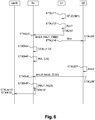
- condition Cnd of the conditional expression relates to a state variable S relative to a device D attached to the central control unit U1, and that the triggered actions concern a home automation device attached to the central unit control unit U1 and a home automation device attached to the central control unit U2, on the basis of the conditional expression example CE described for the configuration method described with reference to FIG. figure 4 .
- a step ETXU11 the central control unit U1 re-evaluates the condition Cnd as defined in the software code module CCM1, this condition being able to be based on a time counter or on state variable values S relating to devices D attached to the central control unit U1;
- a step ETXU12 when the condition Cnd is validated, the central control unit executes part of the actions AcU1 of the conditional expression CE defined in the conditional software code module CCM1, namely the actions that apply to devices attached to the central control unit U1;
- the control unit U1 sends a notification NtU1 to the server Sv, for example in the form of a notification message MnU1 indicating that the condition Cnd of the conditional expression CE has been validated and optionally that its actions have have been triggered, the server receiving this notification message in an ETXSv3 step.
- the notification message includes the identifier of the conditional expression CEID.
- the server identifies the complete definition of the conditional expression CE previously stored thanks to the conditional expression identifier CEID provided in the notification message MN.
- the server determines a selection of involved CPUs XUL in the actions of the conditional expression CE only.
- the central control unit U1 transmitting the notification NtU1 is excluded from the list.
- a condition Cnd of the conditional expression CE which would be only time-based, only those CPUs that do not have support for the evaluation of time-based CE conditional expressions are retained in the selection .
- the server then sends MAc action messages to the selected CPUs to produce the remaining effects that were configured in connection with this conditional expression CE.
- an action message MAc is sent to the control unit U2 which receives it in a step ETXU26.
- the action message MAc may include the identifier of the conditional expression CEID.
- the central control unit U2 executes the AcU2 action (s) corresponding to the action message received, for example relating to a home automation device D attached to it.
- a step ETXU28 the central control unit U2 sends a notification NtU2 in a notification message MNU2, in connection with the identifier of the conditional expression CEID in order to account for the progress of the action, the server receiving this notification message in a step ETXSv8.
- the server determines a result of the actions of the conditional expression CE, by aggregating the received notifications in the different received notification messages MNU1, MNU2, on the basis of the unique identifier of the conditional expression CEID.
- the central unit U1 performing the evaluation of the condition Cnd to add an execution identifier to the unique conditional expression identifier CEID to differentiate the different executions of this module, this execution identifier being propagated to the server and then other central control units concerned in the notification or action messages.
- a reference to the trigger time can be used to aggregate the results.
- Steps ETXU11 'and ETXU12' are similar to steps ETXU11 and ETXU12.
- the control unit U1 sends a notification NtU1 to the server Sv, for example in the form of a notification message MnU1 indicating only that its actions have been triggered, the server receiving this notification message in a step ETXSv3 '.
- the notification message includes the identifier of the conditional expression CEID.
- the first central control unit U1 sends a notification or command message Mnc to the central control unit U2 which receives it in a step ETXU24'.
- This message includes, depending on the use case, an indication that the condition Cnd is fulfilled, an indication that a change of value of the state variable S has taken place, a request to execute a scenario or a command group identified by a script or command group identifier, or explicitly a command or group of commands to execute.
- the steps ETXU27 'and ETXU28' are similar to the steps ETXU27 and ETXU28 described in the embodiment of the figure 5 , as the subsequent steps implemented by the server ETXSv8 'and following.
- this variant of the control method has the additional advantage of ensuring proper operation of the installation even in case of Internet outage.
- the server can still aggregate the execution notifications, as described in the previous example.
- the aggregation of the notification messages makes it possible to update the data recorded in the IDB instance database linked to the representative entity S.
- the server has an up-to-date view of the state of the devices automation.
- the server is able to present the execution of the actions of the conditional expression CE as a single coherent command group, in the same way as an execution would have been. immediate order, even if it is divided and propagated to multiple central control units.
Landscapes
- Engineering & Computer Science (AREA)
- Automation & Control Theory (AREA)
- Computer Networks & Wireless Communication (AREA)
- Signal Processing (AREA)
- Selective Calling Equipment (AREA)
- Telephonic Communication Services (AREA)
Claims (15)
- Verfahren zum Konfigurieren einer Heimautomatisierungsanlage (17), die eine Vielzahl von Heimautomatisierungsvorrichtungen (D) und eine Vielzahl von zentralen Steuereinheiten (U, U1, U2) umfasst; wobei das Verfahren von einer Verwaltungseinheit (Sv) oder von einem mobilen Endgerät (T) ausgeführt wird, die/das mit der Heimautomatisierungsanlage (17) verbunden ist, und dadurch gekennzeichnet ist, dass es die folgenden Schritte umfasst:i. Empfangen (ETCfSv1) einer Konfigurationsnachricht (MCf), die von einem Benutzer (Usr) oder von einer Anwendung (A) stammt, welche auf der Verwaltungseinheit (Sv) oder auf einer anderen verbundenen Verwaltungseinheit ausgeführt wird, wobei die Nachricht (Mcf) eine Definition eines bedingten Ausdrucks (CE) umfasst, der- eine Beurteilung von mindestens einer Bedingung (Cnd), die sich auf:-- mindestens eine Zustandsvariable (S) von mindestens einer Heimautomatisierungsvorrichtung (D), und/oder-- mindestens eine Zeit oder ein Datum bezieht;und- ein bedingtes Auslösen von mindestens einer Aktion (Ac, AcU1, AcU2) definiert;ii. Bestimmen (ETCfSv5) einer Liste (UL), die mindestens eine zentrale Steuereinheit (U, U1, U2) umfasst, die- die mindestens eine Bedingung (Cnd) beurteilen und/oder- die mindestens eine Aktion (Ac, AcU1, AcU2) auslösen kann;iii. Erzeugen (ETCfSv6) von mindestens einem bedingten Softwarecodemodul (CCM), das bei seiner Ausführung durch die mindestens eine in der Liste (UL) umfasste zentrale Steuereinheit (U, U1, U2) die Beurteilung der mindestens einen Bedingung (Cnd) und/oder das Auslösen der mindestens einen Aktion (Ac, AcU1, AcU2) ermöglicht;iv. Senden (ETCfSv7) von mindestens einer Konfigurationsnachricht (MCfU1, MCfU2), die eine Definition des mindestens einen bedingten Softwarecodemoduls (CCM) umfasst, an die mindestens eine zentrale Steuereinheit (U, U1, U2), die in der Liste (UL) umfasst ist.
- Verfahren nach Anspruch 1, das weiter einen Schritt des Aufzeichnens (ETCfSv2) des bedingen Ausdrucks (CE) in Verbindung mit einer Kennung des bedingten Ausdrucks (CEID) umfasst, und wobei der Schritt des Sendens (ETCfSv7) der mindestens einen Konfigurationsnachricht (MCfU1, MCfU2), die die Definition des mindestens einen bedingten Softwarecodemoduls (CCM) umfasst, in Verbindung mit der Kennung des bedingten Ausdrucks (CEID) ausgeführt wird.
- Verfahren nach einem der Ansprüche 1 oder 2, wobei die Verwaltungseinheit (Sv) bestimmt, dass eine zentrale Steuereinheit (U, U1, U2) die mindestens eine Bedingung (Cnd) beurteilen oder die mindestens eine Aktion (Ac, AcU1, AcU2) ausführen kann, wenn:- mindestens eine der Zustandsvariablen (S) einer der Heimautomatisierungsvorrichtungen (D), die an die zentrale Steuereinheit (U1, U2) angebunden sind, in der Bedingung (Cnd) verwendet wird; oder- mindestens eine der Heimautomatisierungsvorrichtungen (D), die an die zentrale Steuereinheit (U1, U2) angebunden sind, in der mindestens einen Aktion (Ac, AcU1, AcU2) verwendet wird.
- Verfahren nach einem der Ansprüche 1 bis 3, das weiter einen Schritt des Bestimmens (ETCfSv4) eines Unterstützungsgrades (SL) umfasst, der von der mindestens einen zentralen Steuereinheit (U) für einen Typ des bedingten Softwarecodemoduls (CCM) bereitgestellt wird; und wobei- das Erzeugen (ETCfSv5) des mindestens einen bedingten Softwarecodemoduls (CCM) auf der Basis des Unterstützungsgrades (SL) ausgeführt wird.
- Verfahren zum Konfigurieren einer Heimautomatisierungsanlage (17), die eine Vielzahl von Heimautomatisierungsvorrichtungen (D) und eine Vielzahl von zentralen Steuereinheiten (U, U1, U2) umfasst; wobei das Verfahren von der mindestens einen zentralen Steuereinheit (U, U1, U2) ausgeführt wird und dadurch gekennzeichnet ist, dass es die folgenden Schritte umfasst:Empfangen (ETCfU17, ETCfU27) einer Konfigurationsnachricht (MCfU1, MCfU2), wobei die Konfigurationsnachricht (MCfU1, MCfU2) von einer Verwaltungseinheit (Sv) oder von einem mobilen Endgerät (T), das mit der Heimautomatisierungsanlage (17) verbunden ist, im Anschluss an den Empfang (ETCfSv1) einer Konfigurationsnachricht (MCf) gesendet (ETCfSv7) wurde, die von einem Benutzer (Usr) oder von einer Anwendung (A) stammt, welche auf der Verwaltungseinheit (Sv) oder auf einer anderen verbundenen Verwaltungseinheit ausgeführt wird, wobei die vom Benutzer (Usr) oder von der Anwendung (A) stammende Nachricht (Mcf) eine Definition eines bedingten Ausdrucks (CE) umfasst, der- eine Beurteilung von mindestens einer Bedingung (Cnd), die sich auf:-- mindestens eine Zustandsvariable (S) von mindestens einer Heimautomatisierungsvorrichtung (D), und/oder-- mindestens eine Zeit oder ein Datum bezieht; und- ein bedingtes Auslösen von mindestens einer Aktion (Ac, AcU1, AcU2) definiert;wobei die Konfigurationsnachricht (MCfU1, MCfU2) eine Definition eines bedingten Softwarecodemoduls (CCM, CCM1, CCM2) umfasst, wobei das bedingte Softwarecodemodul (CCM, CCM1, CCM2) von der Verwaltungseinheit (Sv) oder von dem mobilen Endgerät (T) erzeugt (ETCfSv6) wurde, die/das mit der Heimautomatisierungsanlage (17) verbunden ist, und bei seiner Ausführung:- eine Beurteilung von mindestens einer Bedingung (Cnd), die sich auf-- mindestens eine Zustandsvariable (S) von mindestens einer Heimautomatisierungsvorrichtung (D), die an die mindestens eine zentrale Steuereinheit (U, U1, U2) angebunden ist, und/oder-- mindestens eine Zeit oder ein Datum bezieht;und/oder- ein bedingtes Auslösen von mindestens einer Aktion (Ac, AcU1, AcU2) ermöglicht;i. Aufzeichnen (ETCfU18, ETCfU28) des bedingten Softwarecodemoduls (CCM, CCM1, CCM2);ii. Konfigurieren (ETCfU19, ETCfU29) der zentralen Steuereinheit (U, U1, U2) so, dass sie:- die mindestens eine Bedingung (Cnd) beurteilt; und/oder- die mindestens eine Aktion (Ac, AcU1, AcU2) auslöst, wenn die mindestens eine Bedingung (Cnd) infolge der Beurteilung validiert wird.
- Konfigurationsverfahren nach dem vorstehenden Anspruch, wobei die mindestens eine Steuereinheit (U) so konfiguriert ist, dass sie eine Mitteilungsnachricht an die Verwaltungseinheit (Sv) oder an das mobile Endgerät (T) sendet, die anzeigt, dass die mindestens eine Bedingung (Cnd) des bedingten Softwarecodemoduls CCM validiert wurde und/oder dass die Aktion(en) (AcU1, AcU2) ausgelöst wurden.
- Konfigurationsverfahren nach einem der Ansprüche 5 oder 6, das von einer ersten zentralen Steuereinheit (U, U1, U2) ausgeführt wird, wobei die Konfigurationsnachricht (MCfU1, MCfU2) umfasst- eine Definition von mindestens einer Mitteilungs- oder Steuernachricht (Mnc); und- mindestens eine Kennung einer zweiten zentralen Steuereinheit (U2) der Heimautomatisierungsanlage (17),und wobei die erste zentrale Steuereinheit (U) so konfiguriert ist, dass sie die Mitteilungs- oder Steuernachricht (Mnc) an die zweite zentrale Steuereinheit (U2) sendet, wenn die mindestens eine Bedingung (Cnd) validiert wurde.
- Verfahren zum Steuern einer Heimautomatisierungsanlage (17), wobei die Heimautomatisierungsanlage (17) eine Vielzahl von Heimautomatisierungsvorrichtungen (D) und eine Vielzahl von zentralen Steuereinheiten (U1, U2) umfasst; wobei das Verfahren von einer zentralen Steuereinheit (U1, U2) ausgeführt wird,
wobei das Verfahren die folgenden Schritte umfasst:o. Umsetzen des Konfigurationsverfahrens nach einem der Ansprüche 5 bis 7;i. Beurteilen (ETXU11, ETXU11') der mindestens einen Bedingung (Cnd); und/oderii. Ausführen (ETXU12, ETXU27, ETXU12', ETXU27') der mindestens einen vom bedingten Softwarecodemodul (CCM) definierten Aktion (AcU1, AcU2). - Steuerungsverfahren nach Anspruch 8, wobei das bedingte Softwarecodemodul (CCM, CCM1, CCM2) zuvor in Verbindung mit einer Kennung des bedingten Ausdrucks (CEID) aufgezeichnet wird; und
weiter einen Schritt des Sendens (ETXU13, ETXU28) einer Mitteilungsnachricht (MnU1, MnU2) an eine Verwaltungseinheit (Sv) umfassend, die anzeigt, dass die mindestens eine Bedingung (Cnd) des bedingten Softwarecodemoduls (CCM) bei seiner Beurteilung validiert wurde und/oder dass die mindestens eine Aktion (AcU1, AcU2) in Verbindung mit der Kennung des bedingten Ausdrucks (CEID) ausgeführt wurde. - Steuerungsverfahren nach einem der Ansprüche 8 oder 9, wobei eine erste zentrale Steuereinheit (U1) zuvor dafür konfiguriert wurde, die Beurteilung der mindestens einen Bedingung auszuführen, wobei das Verfahren weiter einen Schritt (ETXU14') des Sendens einer Mitteilungs- oder Steuernachricht (Mnc) an eine zweite zentrale Steuereinheit (U2) der Anlage durch die erste zentrale Steuereinheit (U1) umfasst, wenn die mindestens eine Bedingung (Cnd) von der ersten zentralen Steuereinheit (U1) validiert wurde.
- Verfahren zum Steuern einer Heimautomatisierungsanlage (17), wobei die Heimautomatisierungsanlage (17) eine Vielzahl von Heimautomatisierungsvorrichtungen (D) und eine Vielzahl von zentralen Steuereinheiten (U1, U2) umfasst; wobei das Verfahren von einer Verwaltungseinheit (Sv) oder von einem Endgerät (T) ausgeführt wird, die/das mit der mindestens einen Heimautomatisierungsanlage (17) verbunden ist, und die folgenden Schritte umfasst:o. Umsetzen des Konfigurationsverfahrens nach einem der Ansprüche 1 bis 4;i. Empfangen (ETXSv3) einer von einer sendenden zentralen Steuereinheit (U1, U2) stammenden Mitteilungsnachricht (MnU1, MnU2), die angibt, dass die mindestens eine Bedingung (Cnd) des bedingten Ausdrucks (CE) validiert wurde und/oder dass die mindestens eine Aktion (AcU1, AcU2) ausgeführt wurde;ii. Identifizieren (ETXSv4) einer vollständigen Definition des bedingten Ausdrucks (CE);iii. Bestimmen (ETXSv5) einer Auswahl (XUL) von zentralen Steuereinheiten (U, U1, U2), die an der mindestens einen Aktion (Ac, AcU1, Acu2) des bedingten Ausdrucks (CE) beteiligt sind;iv. Senden (ETXSv6) von mindestens einer Aktionsnachricht (Mac) an mindestens eine in der Auswahl (XUL) umfasste zentrale Steuereinheit (U, U1, U3) im Hinblick auf das Auslösen einer Aktion (AcU1, ACU2) auf einer Heimautomatisierungsvorrichtung (D), die an die zentrale Steuereinheit (U, U1, U2) angebunden ist.
- Verfahren nach Anspruch 11, wobei die im Schritt i empfangene Mitteilungsnachricht eine Kennung (CEID) des bedingten Ausdrucks (CE) bereitstellt; und wobei die vollständige Definition des bedingten Ausdrucks (CE) zuvor in Verbindung mit der Kennung (CEID) gespeichert wird, wobei das Identifizieren (ETXSv4) einer vollständigen Definition des bedingten Ausdrucks (CE) dank der in der Mitteilungsnachricht (MNU1, MnU2) bereitgestellten Kennung (CEID) des bedingten Ausdrucks (CE) ausgeführt werden kann.
- Verfahren nach Anspruch 12, wobei die im Schritt iv gesendete Aktionsnachricht (Mac) die Kennung (CEID) des bedingten Ausdrucks (CE) umfasst, wobei das Verfahren weiter den folgenden Schritt umfasst:- Bestimmen (ETXSv9) eines Ergebnisses der mindestens einen Aktion (AcU1, AcU2) durch Aggregieren einer Vielzahl von Mitteilungen, die in einer Vielzahl von empfangenen Mitteilungsnachrichten (MNU1, MNU2) empfangen werden, auf der Basis der eindeutigen Kennung (CEID) des bedingten Ausdrucks (CE).
- Computerprogrammprodukt, das Codeanweisungen umfasst, die dafür eingerichtet sind, die Schritte eines Verfahrens nach einem der Ansprüche 1 bis 13 umzusetzen, wenn das Programm von einem Prozessor einer Verwaltungseinheit (Sv) oder von einer zentralen Steuereinheit (U1, U2) ausgeführt wird.
- System, das eine Verwaltungseinheit (Sv) oder ein mobiles Endgerät (T) umfasst, die/das dafür eingerichtet ist, das Verfahren nach einem der Ansprüche 1 bis 4 oder 11 bis 13 mit mindestens einer zentralen Steuereinheit (U) einer Heimautomatisierungsanlage (17) verbunden auszuführen, wobei die mindestens eine zentrale Steuereinheit (U) dafür eingerichtet ist, das Verfahren nach einem der Ansprüche 5 bis 10 auszuführen.
Priority Applications (1)
| Application Number | Priority Date | Filing Date | Title |
|---|---|---|---|
| PL16777722T PL3350967T3 (pl) | 2015-09-16 | 2016-09-14 | Sposób konfigurowania i sposób sterowania instalacją automatyki domowej |
Applications Claiming Priority (2)
| Application Number | Priority Date | Filing Date | Title |
|---|---|---|---|
| FR1558667A FR3041198B1 (fr) | 2015-09-16 | 2015-09-16 | Procede de configuration et procede de controle d’une installation domotique |
| PCT/FR2016/052309 WO2017046512A1 (fr) | 2015-09-16 | 2016-09-14 | Procédé de configuration et procédé de contrôle d'une installation domotique |
Publications (2)
| Publication Number | Publication Date |
|---|---|
| EP3350967A1 EP3350967A1 (de) | 2018-07-25 |
| EP3350967B1 true EP3350967B1 (de) | 2019-08-28 |
Family
ID=55135294
Family Applications (1)
| Application Number | Title | Priority Date | Filing Date |
|---|---|---|---|
| EP16777722.6A Active EP3350967B1 (de) | 2015-09-16 | 2016-09-14 | Verfahren zur konfiguration und verfahren zur steuerung einer heimautomationsvorrichtung |
Country Status (8)
| Country | Link |
|---|---|
| US (1) | US11251985B2 (de) |
| EP (1) | EP3350967B1 (de) |
| CN (2) | CN108353009A (de) |
| DK (1) | DK3350967T3 (de) |
| ES (1) | ES2758353T3 (de) |
| FR (1) | FR3041198B1 (de) |
| PL (1) | PL3350967T3 (de) |
| WO (1) | WO2017046512A1 (de) |
Cited By (1)
| Publication number | Priority date | Publication date | Assignee | Title |
|---|---|---|---|---|
| EP4712416A1 (de) * | 2024-09-17 | 2026-03-18 | Delta Dore | Verfahren zur steuerung eines heimautomatisierungssystems |
Families Citing this family (1)
| Publication number | Priority date | Publication date | Assignee | Title |
|---|---|---|---|---|
| US11438238B2 (en) * | 2020-04-06 | 2022-09-06 | Vmware, Inc. | User interface for accessing multi-site logical network |
Family Cites Families (24)
| Publication number | Priority date | Publication date | Assignee | Title |
|---|---|---|---|---|
| US20020016639A1 (en) * | 1996-10-01 | 2002-02-07 | Intelihome, Inc., Texas Corporation | Method and apparatus for improved building automation |
| US6192282B1 (en) * | 1996-10-01 | 2001-02-20 | Intelihome, Inc. | Method and apparatus for improved building automation |
| JP2003125468A (ja) * | 2001-10-19 | 2003-04-25 | Dainippon Printing Co Ltd | 家電機器の遠隔制御システム |
| JP4093899B2 (ja) * | 2003-04-03 | 2008-06-04 | シャープ株式会社 | データ送信装置及びデータ受信装置及びデータ通信システム及びデータ通信管理用サーバ |
| US8103717B2 (en) | 2005-10-06 | 2012-01-24 | Mitsubishi Electric Corporation | Terminal apparatus, server apparatus, and instruction apparatus |
| US7937716B2 (en) * | 2007-09-05 | 2011-05-03 | International Business Machines Corporation | Managing collections of appliances |
| KR20090095441A (ko) * | 2008-03-04 | 2009-09-09 | 삼성전자주식회사 | 홈 네트워크에서 소프트웨어 생명 주기를 관리하는 방법 및장치 |
| US8994539B2 (en) * | 2008-10-27 | 2015-03-31 | Lennox Industries, Inc. | Alarm and diagnostics system and method for a distributed-architecture heating, ventilation and air conditioning network |
| CN101452483B (zh) | 2008-12-25 | 2011-06-08 | 阿里巴巴集团控股有限公司 | 网站访问方法及系统 |
| CN101459559B (zh) * | 2008-12-26 | 2011-05-11 | 中兴通讯股份有限公司 | 一种对监控用户配置信息进行存储及管理的方法与系统 |
| CN101621406B (zh) * | 2009-07-28 | 2012-12-26 | 中兴通讯股份有限公司 | 一种批量配置家庭网关的方法、配置设备及家庭网关 |
| US8705371B2 (en) * | 2010-03-19 | 2014-04-22 | At&T Intellectual Property I, L.P. | Locally diagnosing and troubleshooting service issues |
| CN101995867A (zh) * | 2010-11-07 | 2011-03-30 | 上海我度多媒体信息技术有限公司 | 基于网络的智能监控系统和智能控制器 |
| CN102938755B (zh) * | 2011-08-15 | 2017-08-25 | 华为技术有限公司 | 智能空间访问方法、系统、控制器和智能空间接口服务器 |
| FR2995105B1 (fr) * | 2012-09-06 | 2014-09-19 | Somfy Sas | Unite nomade de commande des conditions de confort et/ou de securite dans un batiment |
| US9705962B2 (en) * | 2012-09-15 | 2017-07-11 | Honeywell International Inc. | Asynchronous reporting system |
| JP6231327B2 (ja) * | 2012-09-28 | 2017-11-15 | パナソニック インテレクチュアル プロパティ コーポレーション オブ アメリカPanasonic Intellectual Property Corporation of America | 端末制御方法、端末制御システム、及び、サーバ装置 |
| CN104885406B (zh) * | 2012-12-18 | 2019-06-21 | 三星电子株式会社 | 用于在家庭网络系统中远程控制家庭设备的方法和设备 |
| JP2014239369A (ja) * | 2013-06-10 | 2014-12-18 | 大和ハウス工業株式会社 | エネルギー消費機器制御装置及びエネルギー消費機器制御方法 |
| CN104062962B (zh) * | 2014-07-01 | 2017-06-20 | 宁波市北仑海伯精密机械制造有限公司 | 一种物联网设备自动控制系统及其控制方法 |
| CN104486416B (zh) | 2014-12-16 | 2018-01-26 | 三星电子(中国)研发中心 | 一种智能家居服务规则的综合利用系统及方法 |
| FR3038478B1 (fr) * | 2015-07-03 | 2018-07-06 | Somfy Sas | Installation domotique et procede de constitution de la topologie d’une installation domotique |
| FR3038479B1 (fr) * | 2015-07-03 | 2017-07-14 | Somfy Sas | Procede de decouverte de la configuration d’une installation domotique |
| FR3038477B1 (fr) * | 2015-07-03 | 2018-07-06 | Somfy Sas | Procede de controle d’une installation domotique |
-
2015
- 2015-09-16 FR FR1558667A patent/FR3041198B1/fr not_active Expired - Fee Related
-
2016
- 2016-09-14 WO PCT/FR2016/052309 patent/WO2017046512A1/fr not_active Ceased
- 2016-09-14 PL PL16777722T patent/PL3350967T3/pl unknown
- 2016-09-14 CN CN201680066731.3A patent/CN108353009A/zh active Pending
- 2016-09-14 ES ES16777722T patent/ES2758353T3/es active Active
- 2016-09-14 DK DK16777722T patent/DK3350967T3/da active
- 2016-09-14 EP EP16777722.6A patent/EP3350967B1/de active Active
- 2016-09-14 CN CN202210278865.9A patent/CN114584417B/zh active Active
- 2016-09-14 US US15/760,018 patent/US11251985B2/en active Active
Non-Patent Citations (1)
| Title |
|---|
| None * |
Cited By (2)
| Publication number | Priority date | Publication date | Assignee | Title |
|---|---|---|---|---|
| EP4712416A1 (de) * | 2024-09-17 | 2026-03-18 | Delta Dore | Verfahren zur steuerung eines heimautomatisierungssystems |
| FR3166507A1 (fr) * | 2024-09-17 | 2026-03-20 | Delta Dore | Procédé de contrôle d’un système domotique |
Also Published As
| Publication number | Publication date |
|---|---|
| FR3041198B1 (fr) | 2018-08-17 |
| US11251985B2 (en) | 2022-02-15 |
| DK3350967T3 (da) | 2019-11-18 |
| WO2017046512A1 (fr) | 2017-03-23 |
| WO2017046512A9 (fr) | 2017-05-26 |
| CN114584417B (zh) | 2024-08-06 |
| US20180270078A1 (en) | 2018-09-20 |
| FR3041198A1 (fr) | 2017-03-17 |
| CN108353009A (zh) | 2018-07-31 |
| EP3350967A1 (de) | 2018-07-25 |
| ES2758353T3 (es) | 2020-05-05 |
| PL3350967T3 (pl) | 2020-05-18 |
| CN114584417A (zh) | 2022-06-03 |
Similar Documents
| Publication | Publication Date | Title |
|---|---|---|
| EP3318035B1 (de) | Verfahren zur steuerung einer heimautomationsanlage | |
| EP3563557B1 (de) | Verfahren zur konfiguration des zugangs zu sowie der fernsteuerung und überwachung von mindestens einer heimautomationsvorrichtung als teil einer heimautomatisierungsanlage | |
| EP3563556B1 (de) | Verfahren zur fernkonfiguration des zugangs zu sowie der steuerung und überwachung von mindestens einer heimautomationsvorrichtung als teil einer heimautomatisierungsanlage | |
| EP3318019B1 (de) | Heimautomatisierungssystem und verfahren zur erzeugung von topologie eines heimautomatisierungssystems | |
| EP3318018B1 (de) | Verfahren zum registrieren einer zentralen steuereinheit einer heimautomatisierungsanlage und entsprechende computerprogrammprodukte | |
| EP3350967B1 (de) | Verfahren zur konfiguration und verfahren zur steuerung einer heimautomationsvorrichtung | |
| WO2016193636A1 (fr) | Procédés de génération de module de code logiciel conditionnel et procédé de contrôle d'au moins une installation domotique d'un bâtiment | |
| EP3318017B1 (de) | Verfahren zur entdeckung der konfiguration einer heimautomatisierungsanlage | |
| EP3384635B1 (de) | Verfahren zur konfiguration, steuerung oder überwachung einer heimautomationsanlage | |
| EP3639484A1 (de) | Verfahren zum konfigurieren einer zu einer domotikanlage gehörenden domotikvorrichtung | |
| EP3262470B1 (de) | Verfahren zur konfiguration und verfahren zum befehlen und/oder steuern einer heimautomatisierungsgerätschnittstelle | |
| EP3639483B1 (de) | Verfahren zur konfiguration einer zentralen steuereinheit eines heimautomatisierungssystems | |
| EP3317731A1 (de) | Verfahren zur steuerung und verfahren zum konfigurieren einer heimautomatisierungsanlage | |
| EP3317732B1 (de) | Verfahren zur anmeldung einer zentralen steuereinheit einer heimautomatisierungsanlage |
Legal Events
| Date | Code | Title | Description |
|---|---|---|---|
| STAA | Information on the status of an ep patent application or granted ep patent |
Free format text: STATUS: THE INTERNATIONAL PUBLICATION HAS BEEN MADE |
|
| PUAI | Public reference made under article 153(3) epc to a published international application that has entered the european phase |
Free format text: ORIGINAL CODE: 0009012 |
|
| STAA | Information on the status of an ep patent application or granted ep patent |
Free format text: STATUS: REQUEST FOR EXAMINATION WAS MADE |
|
| 17P | Request for examination filed |
Effective date: 20180307 |
|
| AK | Designated contracting states |
Kind code of ref document: A1 Designated state(s): AL AT BE BG CH CY CZ DE DK EE ES FI FR GB GR HR HU IE IS IT LI LT LU LV MC MK MT NL NO PL PT RO RS SE SI SK SM TR |
|
| AX | Request for extension of the european patent |
Extension state: BA ME |
|
| DAV | Request for validation of the european patent (deleted) | ||
| DAX | Request for extension of the european patent (deleted) | ||
| GRAP | Despatch of communication of intention to grant a patent |
Free format text: ORIGINAL CODE: EPIDOSNIGR1 |
|
| STAA | Information on the status of an ep patent application or granted ep patent |
Free format text: STATUS: GRANT OF PATENT IS INTENDED |
|
| INTG | Intention to grant announced |
Effective date: 20190322 |
|
| GRAS | Grant fee paid |
Free format text: ORIGINAL CODE: EPIDOSNIGR3 |
|
| GRAA | (expected) grant |
Free format text: ORIGINAL CODE: 0009210 |
|
| STAA | Information on the status of an ep patent application or granted ep patent |
Free format text: STATUS: THE PATENT HAS BEEN GRANTED |
|
| AK | Designated contracting states |
Kind code of ref document: B1 Designated state(s): AL AT BE BG CH CY CZ DE DK EE ES FI FR GB GR HR HU IE IS IT LI LT LU LV MC MK MT NL NO PL PT RO RS SE SI SK SM TR |
|
| REG | Reference to a national code |
Ref country code: GB Ref legal event code: FG4D Free format text: NOT ENGLISH |
|
| REG | Reference to a national code |
Ref country code: CH Ref legal event code: EP |
|
| REG | Reference to a national code |
Ref country code: AT Ref legal event code: REF Ref document number: 1173783 Country of ref document: AT Kind code of ref document: T Effective date: 20190915 |
|
| REG | Reference to a national code |
Ref country code: IE Ref legal event code: FG4D Free format text: LANGUAGE OF EP DOCUMENT: FRENCH |
|
| REG | Reference to a national code |
Ref country code: DE Ref legal event code: R096 Ref document number: 602016019548 Country of ref document: DE |
|
| REG | Reference to a national code |
Ref country code: DK Ref legal event code: T3 Effective date: 20191114 |
|
| REG | Reference to a national code |
Ref country code: CH Ref legal event code: NV Representative=s name: CABINET GERMAIN AND MAUREAU, CH |
|
| REG | Reference to a national code |
Ref country code: NL Ref legal event code: FP |
|
| REG | Reference to a national code |
Ref country code: LT Ref legal event code: MG4D |
|
| PG25 | Lapsed in a contracting state [announced via postgrant information from national office to epo] |
Ref country code: NO Free format text: LAPSE BECAUSE OF FAILURE TO SUBMIT A TRANSLATION OF THE DESCRIPTION OR TO PAY THE FEE WITHIN THE PRESCRIBED TIME-LIMIT Effective date: 20191128 Ref country code: PT Free format text: LAPSE BECAUSE OF FAILURE TO SUBMIT A TRANSLATION OF THE DESCRIPTION OR TO PAY THE FEE WITHIN THE PRESCRIBED TIME-LIMIT Effective date: 20191230 Ref country code: FI Free format text: LAPSE BECAUSE OF FAILURE TO SUBMIT A TRANSLATION OF THE DESCRIPTION OR TO PAY THE FEE WITHIN THE PRESCRIBED TIME-LIMIT Effective date: 20190828 Ref country code: HR Free format text: LAPSE BECAUSE OF FAILURE TO SUBMIT A TRANSLATION OF THE DESCRIPTION OR TO PAY THE FEE WITHIN THE PRESCRIBED TIME-LIMIT Effective date: 20190828 Ref country code: SE Free format text: LAPSE BECAUSE OF FAILURE TO SUBMIT A TRANSLATION OF THE DESCRIPTION OR TO PAY THE FEE WITHIN THE PRESCRIBED TIME-LIMIT Effective date: 20190828 Ref country code: BG Free format text: LAPSE BECAUSE OF FAILURE TO SUBMIT A TRANSLATION OF THE DESCRIPTION OR TO PAY THE FEE WITHIN THE PRESCRIBED TIME-LIMIT Effective date: 20191128 Ref country code: LT Free format text: LAPSE BECAUSE OF FAILURE TO SUBMIT A TRANSLATION OF THE DESCRIPTION OR TO PAY THE FEE WITHIN THE PRESCRIBED TIME-LIMIT Effective date: 20190828 |
|
| PG25 | Lapsed in a contracting state [announced via postgrant information from national office to epo] |
Ref country code: AL Free format text: LAPSE BECAUSE OF FAILURE TO SUBMIT A TRANSLATION OF THE DESCRIPTION OR TO PAY THE FEE WITHIN THE PRESCRIBED TIME-LIMIT Effective date: 20190828 Ref country code: LV Free format text: LAPSE BECAUSE OF FAILURE TO SUBMIT A TRANSLATION OF THE DESCRIPTION OR TO PAY THE FEE WITHIN THE PRESCRIBED TIME-LIMIT Effective date: 20190828 Ref country code: IS Free format text: LAPSE BECAUSE OF FAILURE TO SUBMIT A TRANSLATION OF THE DESCRIPTION OR TO PAY THE FEE WITHIN THE PRESCRIBED TIME-LIMIT Effective date: 20191228 Ref country code: GR Free format text: LAPSE BECAUSE OF FAILURE TO SUBMIT A TRANSLATION OF THE DESCRIPTION OR TO PAY THE FEE WITHIN THE PRESCRIBED TIME-LIMIT Effective date: 20191129 Ref country code: RS Free format text: LAPSE BECAUSE OF FAILURE TO SUBMIT A TRANSLATION OF THE DESCRIPTION OR TO PAY THE FEE WITHIN THE PRESCRIBED TIME-LIMIT Effective date: 20190828 |
|
| PGFP | Annual fee paid to national office [announced via postgrant information from national office to epo] |
Ref country code: DK Payment date: 20191113 Year of fee payment: 4 Ref country code: ES Payment date: 20191105 Year of fee payment: 4 |
|
| REG | Reference to a national code |
Ref country code: AT Ref legal event code: MK05 Ref document number: 1173783 Country of ref document: AT Kind code of ref document: T Effective date: 20190828 |
|
| PG25 | Lapsed in a contracting state [announced via postgrant information from national office to epo] |
Ref country code: TR Free format text: LAPSE BECAUSE OF FAILURE TO SUBMIT A TRANSLATION OF THE DESCRIPTION OR TO PAY THE FEE WITHIN THE PRESCRIBED TIME-LIMIT Effective date: 20190828 |
|
| PG25 | Lapsed in a contracting state [announced via postgrant information from national office to epo] |
Ref country code: RO Free format text: LAPSE BECAUSE OF FAILURE TO SUBMIT A TRANSLATION OF THE DESCRIPTION OR TO PAY THE FEE WITHIN THE PRESCRIBED TIME-LIMIT Effective date: 20190828 Ref country code: AT Free format text: LAPSE BECAUSE OF FAILURE TO SUBMIT A TRANSLATION OF THE DESCRIPTION OR TO PAY THE FEE WITHIN THE PRESCRIBED TIME-LIMIT Effective date: 20190828 Ref country code: EE Free format text: LAPSE BECAUSE OF FAILURE TO SUBMIT A TRANSLATION OF THE DESCRIPTION OR TO PAY THE FEE WITHIN THE PRESCRIBED TIME-LIMIT Effective date: 20190828 |
|
| PGFP | Annual fee paid to national office [announced via postgrant information from national office to epo] |
Ref country code: IT Payment date: 20190930 Year of fee payment: 4 |
|
| REG | Reference to a national code |
Ref country code: ES Ref legal event code: FG2A Ref document number: 2758353 Country of ref document: ES Kind code of ref document: T3 Effective date: 20200505 |
|
| PG25 | Lapsed in a contracting state [announced via postgrant information from national office to epo] |
Ref country code: CZ Free format text: LAPSE BECAUSE OF FAILURE TO SUBMIT A TRANSLATION OF THE DESCRIPTION OR TO PAY THE FEE WITHIN THE PRESCRIBED TIME-LIMIT Effective date: 20190828 Ref country code: IS Free format text: LAPSE BECAUSE OF FAILURE TO SUBMIT A TRANSLATION OF THE DESCRIPTION OR TO PAY THE FEE WITHIN THE PRESCRIBED TIME-LIMIT Effective date: 20200224 Ref country code: SM Free format text: LAPSE BECAUSE OF FAILURE TO SUBMIT A TRANSLATION OF THE DESCRIPTION OR TO PAY THE FEE WITHIN THE PRESCRIBED TIME-LIMIT Effective date: 20190828 Ref country code: MC Free format text: LAPSE BECAUSE OF FAILURE TO SUBMIT A TRANSLATION OF THE DESCRIPTION OR TO PAY THE FEE WITHIN THE PRESCRIBED TIME-LIMIT Effective date: 20190828 Ref country code: SK Free format text: LAPSE BECAUSE OF FAILURE TO SUBMIT A TRANSLATION OF THE DESCRIPTION OR TO PAY THE FEE WITHIN THE PRESCRIBED TIME-LIMIT Effective date: 20190828 |
|
| REG | Reference to a national code |
Ref country code: DE Ref legal event code: R097 Ref document number: 602016019548 Country of ref document: DE |
|
| PLBE | No opposition filed within time limit |
Free format text: ORIGINAL CODE: 0009261 |
|
| STAA | Information on the status of an ep patent application or granted ep patent |
Free format text: STATUS: NO OPPOSITION FILED WITHIN TIME LIMIT |
|
| PG2D | Information on lapse in contracting state deleted |
Ref country code: IS |
|
| PG25 | Lapsed in a contracting state [announced via postgrant information from national office to epo] |
Ref country code: LU Free format text: LAPSE BECAUSE OF NON-PAYMENT OF DUE FEES Effective date: 20190914 Ref country code: IE Free format text: LAPSE BECAUSE OF NON-PAYMENT OF DUE FEES Effective date: 20190914 |
|
| 26N | No opposition filed |
Effective date: 20200603 |
|
| REG | Reference to a national code |
Ref country code: BE Ref legal event code: MM Effective date: 20190930 |
|
| PG25 | Lapsed in a contracting state [announced via postgrant information from national office to epo] |
Ref country code: BE Free format text: LAPSE BECAUSE OF NON-PAYMENT OF DUE FEES Effective date: 20190930 Ref country code: SI Free format text: LAPSE BECAUSE OF FAILURE TO SUBMIT A TRANSLATION OF THE DESCRIPTION OR TO PAY THE FEE WITHIN THE PRESCRIBED TIME-LIMIT Effective date: 20190828 |
|
| REG | Reference to a national code |
Ref country code: DK Ref legal event code: EBP Effective date: 20200930 |
|
| GBPC | Gb: european patent ceased through non-payment of renewal fee |
Effective date: 20200914 |
|
| PG25 | Lapsed in a contracting state [announced via postgrant information from national office to epo] |
Ref country code: CY Free format text: LAPSE BECAUSE OF FAILURE TO SUBMIT A TRANSLATION OF THE DESCRIPTION OR TO PAY THE FEE WITHIN THE PRESCRIBED TIME-LIMIT Effective date: 20190828 |
|
| PG25 | Lapsed in a contracting state [announced via postgrant information from national office to epo] |
Ref country code: MT Free format text: LAPSE BECAUSE OF FAILURE TO SUBMIT A TRANSLATION OF THE DESCRIPTION OR TO PAY THE FEE WITHIN THE PRESCRIBED TIME-LIMIT Effective date: 20190828 Ref country code: HU Free format text: LAPSE BECAUSE OF FAILURE TO SUBMIT A TRANSLATION OF THE DESCRIPTION OR TO PAY THE FEE WITHIN THE PRESCRIBED TIME-LIMIT; INVALID AB INITIO Effective date: 20160914 |
|
| PG25 | Lapsed in a contracting state [announced via postgrant information from national office to epo] |
Ref country code: GB Free format text: LAPSE BECAUSE OF NON-PAYMENT OF DUE FEES Effective date: 20200914 |
|
| PG25 | Lapsed in a contracting state [announced via postgrant information from national office to epo] |
Ref country code: IT Free format text: LAPSE BECAUSE OF NON-PAYMENT OF DUE FEES Effective date: 20200914 |
|
| PG25 | Lapsed in a contracting state [announced via postgrant information from national office to epo] |
Ref country code: DK Free format text: LAPSE BECAUSE OF NON-PAYMENT OF DUE FEES Effective date: 20200930 |
|
| REG | Reference to a national code |
Ref country code: ES Ref legal event code: FD2A Effective date: 20220114 |
|
| PG25 | Lapsed in a contracting state [announced via postgrant information from national office to epo] |
Ref country code: ES Free format text: LAPSE BECAUSE OF NON-PAYMENT OF DUE FEES Effective date: 20200915 |
|
| PG25 | Lapsed in a contracting state [announced via postgrant information from national office to epo] |
Ref country code: MK Free format text: LAPSE BECAUSE OF FAILURE TO SUBMIT A TRANSLATION OF THE DESCRIPTION OR TO PAY THE FEE WITHIN THE PRESCRIBED TIME-LIMIT Effective date: 20190828 |
|
| REG | Reference to a national code |
Ref country code: DE Ref legal event code: R081 Ref document number: 602016019548 Country of ref document: DE Owner name: SOMFY ACTIVITES SA, FR Free format text: FORMER OWNER: OVERKIZ, METZ-TESSI, FR |
|
| REG | Reference to a national code |
Ref country code: NL Ref legal event code: PD Owner name: SOMFY ACTIVITES SA; FR Free format text: DETAILS ASSIGNMENT: CHANGE OF OWNER(S), ASSIGNMENT; FORMER OWNER NAME: OVERKIZ Effective date: 20221213 |
|
| REG | Reference to a national code |
Ref country code: CH Ref legal event code: U11 Free format text: ST27 STATUS EVENT CODE: U-0-0-U10-U11 (AS PROVIDED BY THE NATIONAL OFFICE) Effective date: 20251009 |
|
| PGFP | Annual fee paid to national office [announced via postgrant information from national office to epo] |
Ref country code: DE Payment date: 20250829 Year of fee payment: 10 |
|
| PGFP | Annual fee paid to national office [announced via postgrant information from national office to epo] |
Ref country code: PL Payment date: 20250826 Year of fee payment: 10 Ref country code: NL Payment date: 20250829 Year of fee payment: 10 |
|
| PGFP | Annual fee paid to national office [announced via postgrant information from national office to epo] |
Ref country code: FR Payment date: 20250722 Year of fee payment: 10 |
|
| PGFP | Annual fee paid to national office [announced via postgrant information from national office to epo] |
Ref country code: CH Payment date: 20251009 Year of fee payment: 10 |