EP3351176A1 - Röntgenbildgebungsvorrichtung und steuerungsverfahren dafür - Google Patents
Röntgenbildgebungsvorrichtung und steuerungsverfahren dafür Download PDFInfo
- Publication number
- EP3351176A1 EP3351176A1 EP18151220.3A EP18151220A EP3351176A1 EP 3351176 A1 EP3351176 A1 EP 3351176A1 EP 18151220 A EP18151220 A EP 18151220A EP 3351176 A1 EP3351176 A1 EP 3351176A1
- Authority
- EP
- European Patent Office
- Prior art keywords
- ray
- raying
- camera image
- thickness
- imaging apparatus
- Prior art date
- Legal status (The legal status is an assumption and is not a legal conclusion. Google has not performed a legal analysis and makes no representation as to the accuracy of the status listed.)
- Granted
Links
Images






Classifications
-
- A—HUMAN NECESSITIES
- A61—MEDICAL OR VETERINARY SCIENCE; HYGIENE
- A61B—DIAGNOSIS; SURGERY; IDENTIFICATION
- A61B6/00—Apparatus or devices for radiation diagnosis; Apparatus or devices for radiation diagnosis combined with radiation therapy equipment
- A61B6/52—Devices using data or image processing specially adapted for radiation diagnosis
- A61B6/5211—Devices using data or image processing specially adapted for radiation diagnosis involving processing of medical diagnostic data
- A61B6/5229—Devices using data or image processing specially adapted for radiation diagnosis involving processing of medical diagnostic data combining image data of a patient, e.g. combining a functional image with an anatomical image
- A61B6/5247—Devices using data or image processing specially adapted for radiation diagnosis involving processing of medical diagnostic data combining image data of a patient, e.g. combining a functional image with an anatomical image combining images from an ionising-radiation diagnostic technique and a non-ionising radiation diagnostic technique, e.g. X-ray and ultrasound
-
- A—HUMAN NECESSITIES
- A61—MEDICAL OR VETERINARY SCIENCE; HYGIENE
- A61B—DIAGNOSIS; SURGERY; IDENTIFICATION
- A61B6/00—Apparatus or devices for radiation diagnosis; Apparatus or devices for radiation diagnosis combined with radiation therapy equipment
- A61B6/54—Control of apparatus or devices for radiation diagnosis
- A61B6/542—Control of apparatus or devices for radiation diagnosis involving control of exposure
- A61B6/544—Control of apparatus or devices for radiation diagnosis involving control of exposure dependent on patient size
-
- A—HUMAN NECESSITIES
- A61—MEDICAL OR VETERINARY SCIENCE; HYGIENE
- A61B—DIAGNOSIS; SURGERY; IDENTIFICATION
- A61B5/00—Measuring for diagnostic purposes; Identification of persons
- A61B5/0059—Measuring for diagnostic purposes; Identification of persons using light, e.g. diagnosis by transillumination, diascopy, fluorescence
- A61B5/0077—Devices for viewing the surface of the body, e.g. camera, magnifying lens
-
- A—HUMAN NECESSITIES
- A61—MEDICAL OR VETERINARY SCIENCE; HYGIENE
- A61B—DIAGNOSIS; SURGERY; IDENTIFICATION
- A61B6/00—Apparatus or devices for radiation diagnosis; Apparatus or devices for radiation diagnosis combined with radiation therapy equipment
- A61B6/40—Arrangements for generating radiation specially adapted for radiation diagnosis
-
- A—HUMAN NECESSITIES
- A61—MEDICAL OR VETERINARY SCIENCE; HYGIENE
- A61B—DIAGNOSIS; SURGERY; IDENTIFICATION
- A61B6/00—Apparatus or devices for radiation diagnosis; Apparatus or devices for radiation diagnosis combined with radiation therapy equipment
- A61B6/42—Arrangements for detecting radiation specially adapted for radiation diagnosis
-
- A—HUMAN NECESSITIES
- A61—MEDICAL OR VETERINARY SCIENCE; HYGIENE
- A61B—DIAGNOSIS; SURGERY; IDENTIFICATION
- A61B6/00—Apparatus or devices for radiation diagnosis; Apparatus or devices for radiation diagnosis combined with radiation therapy equipment
- A61B6/54—Control of apparatus or devices for radiation diagnosis
-
- G—PHYSICS
- G01—MEASURING; TESTING
- G01B—MEASURING LENGTH, THICKNESS OR SIMILAR LINEAR DIMENSIONS; MEASURING ANGLES; MEASURING AREAS; MEASURING IRREGULARITIES OF SURFACES OR CONTOURS
- G01B15/00—Measuring arrangements characterised by the use of electromagnetic waves or particle radiation, e.g. by the use of microwaves, X-rays, gamma rays or electrons
- G01B15/02—Measuring arrangements characterised by the use of electromagnetic waves or particle radiation, e.g. by the use of microwaves, X-rays, gamma rays or electrons for measuring thickness
-
- G—PHYSICS
- G01—MEASURING; TESTING
- G01T—MEASUREMENT OF NUCLEAR OR X-RADIATION
- G01T1/00—Measuring X-radiation, gamma radiation, corpuscular radiation, or cosmic radiation
- G01T1/16—Measuring radiation intensity
- G01T1/17—Circuit arrangements not adapted to a particular type of detector
-
- G—PHYSICS
- G06—COMPUTING OR CALCULATING; COUNTING
- G06F—ELECTRIC DIGITAL DATA PROCESSING
- G06F3/00—Input arrangements for transferring data to be processed into a form capable of being handled by the computer; Output arrangements for transferring data from processing unit to output unit, e.g. interface arrangements
- G06F3/002—Specific input/output arrangements not covered by G06F3/01 - G06F3/16
- G06F3/005—Input arrangements through a video camera
-
- G—PHYSICS
- G06—COMPUTING OR CALCULATING; COUNTING
- G06F—ELECTRIC DIGITAL DATA PROCESSING
- G06F3/00—Input arrangements for transferring data to be processed into a form capable of being handled by the computer; Output arrangements for transferring data from processing unit to output unit, e.g. interface arrangements
- G06F3/01—Input arrangements or combined input and output arrangements for interaction between user and computer
- G06F3/017—Gesture based interaction, e.g. based on a set of recognized hand gestures
-
- G—PHYSICS
- G06—COMPUTING OR CALCULATING; COUNTING
- G06V—IMAGE OR VIDEO RECOGNITION OR UNDERSTANDING
- G06V40/00—Recognition of biometric, human-related or animal-related patterns in image or video data
- G06V40/20—Movements or behaviour, e.g. gesture recognition
-
- H—ELECTRICITY
- H04—ELECTRIC COMMUNICATION TECHNIQUE
- H04N—PICTORIAL COMMUNICATION, e.g. TELEVISION
- H04N13/00—Stereoscopic video systems; Multi-view video systems; Details thereof
- H04N13/20—Image signal generators
- H04N13/204—Image signal generators using stereoscopic image cameras
-
- A—HUMAN NECESSITIES
- A61—MEDICAL OR VETERINARY SCIENCE; HYGIENE
- A61B—DIAGNOSIS; SURGERY; IDENTIFICATION
- A61B6/00—Apparatus or devices for radiation diagnosis; Apparatus or devices for radiation diagnosis combined with radiation therapy equipment
- A61B6/06—Diaphragms
-
- A—HUMAN NECESSITIES
- A61—MEDICAL OR VETERINARY SCIENCE; HYGIENE
- A61B—DIAGNOSIS; SURGERY; IDENTIFICATION
- A61B6/00—Apparatus or devices for radiation diagnosis; Apparatus or devices for radiation diagnosis combined with radiation therapy equipment
- A61B6/08—Auxiliary means for directing the radiation beam to a particular spot, e.g. using light beams
-
- A—HUMAN NECESSITIES
- A61—MEDICAL OR VETERINARY SCIENCE; HYGIENE
- A61B—DIAGNOSIS; SURGERY; IDENTIFICATION
- A61B6/00—Apparatus or devices for radiation diagnosis; Apparatus or devices for radiation diagnosis combined with radiation therapy equipment
- A61B6/44—Constructional features of apparatus for radiation diagnosis
- A61B6/4405—Constructional features of apparatus for radiation diagnosis the apparatus being movable or portable, e.g. handheld or mounted on a trolley
-
- A—HUMAN NECESSITIES
- A61—MEDICAL OR VETERINARY SCIENCE; HYGIENE
- A61B—DIAGNOSIS; SURGERY; IDENTIFICATION
- A61B6/00—Apparatus or devices for radiation diagnosis; Apparatus or devices for radiation diagnosis combined with radiation therapy equipment
- A61B6/44—Constructional features of apparatus for radiation diagnosis
- A61B6/4429—Constructional features of apparatus for radiation diagnosis related to the mounting of source units and detector units
- A61B6/4464—Constructional features of apparatus for radiation diagnosis related to the mounting of source units and detector units the source unit or the detector unit being mounted to ceiling
Definitions
- the present disclosure relates to an X-ray imaging apparatus equipped with a camera and control method thereof.
- X-ray imaging apparatuses are devices for allowing the user to see an internal structure of a subject by irradiating X-rays to the subject and analyzing X-rays that have passed through the subject.
- X-ray transmittance is different depending on the tissue of a subject, so the internal structure of the subject may be imaged using an attenuation coefficient quantified from the X-ray transmittance.
- SOD Source to Object Distance
- SID Source to Image receptor Distance
- an X-ray imaging apparatus comprising an X-ray source configured to generate and irradiate an X-ray; a photographing device equipped in the X-ray source for capturing a camera image; and a controller configured to detect a plurality of indicators from the camera image, calculate a thickness of an X-raying portion of a subject based on a distance between the plurality of indicators, and controlling an X-ray irradiation condition based on the thickness of the X-raying portion.
- the plurality of indicators may comprise both hands of a user.
- the photographing device may comprise at least one of a three dimensional (3D) camera, a depth camera, and a stereo camera which are able to obtain depth information.
- 3D three dimensional
- the camera image may have one of the hands of the user located in front of the X-raying portion of the subject and the other of the hands of the user located a distance of the thickness of the X-raying portion away from the one hand.
- the X-ray irradiation condition may comprise at least one of a tube voltage, a tube current, an exposure time, a filter type, filter thickness, a target material of anode, a focal size, a grid angle, a center position of the grid, and a field of view (FOV).
- a tube voltage a tube current
- a target material of anode a focal size
- a grid angle a center position of the grid
- FOV field of view
- the controller may be configured to calculate a distance between the hands using a camera image captured at a point when a preset event occurs if the preset event occurs.
- the controller may be configured to determine that the preset event has occurred if recognizing that at least one of the hands makes a pre-registered gesture.
- the controller may be configured to recognize an X-raying portion of the subject from the camera image and set an X-raying protocol based on the recognized X-raying portion.
- the controller may be configured to recognize a portion where at least one of the hands of the user is located in the camera image as the X-raying portion.
- the controller may be configured to control the X-ray irradiation condition based on the calculated distance between the hands and the set X-raying protocol.
- the controller is configured to detect a center position of at least one of the hands of the user in the camera image and move the X-ray source to a position corresponding to the center position.
- the controller is configured to detect an angle of at least one of the hands of the user in the camera image and control an angle of the X-ray source to correspond to the angle of the detected one hand.
- the controller may be configured to detect the plurality of indicators in the camera image when performing X-raying in a portable mode.
- a control method of an X-ray imaging apparatus comprising: capturing a camera image using a photographing device equipped in an X-ray source; detecting a plurality of indicators in the camera image; calculating a thickness of an X-raying portion of a subject based on a distance between the plurality of indicators; and controlling an X-ray irradiation condition based on the thickness of the X-raying portion.
- the plurality of indicators may comprise both hands of a user.
- the photographing device may comprise a three dimensional (3D) camera able to acquire depth information.
- 3D three dimensional
- the camera image may have one of the hands of the user located in front of the X-raying portion of the subject and the other of the hands of the user located a distance of the thickness of the X-raying portion away from the one hand.
- the method may further comprise determining whether a preset event occurs, and the calculating a distance between the detected hands may comprise calculating a distance between the hands using a camera image captured at a point when the preset event occurs if the preset event occurs.
- Determining whether a preset event occurs may comprise determining that the preset event has occurred if recognizing that at least one of the hands makes a pre-registered gesture.
- various functions described below can be implemented or supported by one or more computer programs, each of which is formed from computer readable program code and embodied in a computer readable medium.
- application and “program” refer to one or more computer programs, software components, sets of instructions, procedures, functions, objects, classes, instances, related data, or a portion thereof adapted for implementation in a suitable computer readable program code.
- computer readable program code includes any type of computer code, including source code, object code, and executable code.
- computer readable medium includes any type of medium capable of being accessed by a computer, such as read only memory (ROM), random access memory (RAM), a hard disk drive, a compact disc (CD), a digital video disc (DVD), or any other type of memory.
- ROM read only memory
- RAM random access memory
- CD compact disc
- DVD digital video disc
- a "non-transitory” computer readable medium excludes wired, wireless, optical, or other communication links that transport transitory electrical or other signals.
- a non-transitory computer readable medium includes media where data can be permanently stored and media where data can be stored and later overwritten, such as a rewritable optical disc or an erasable memory device.
- FIGS. 1 through 14 discussed below, and the various embodiments used to describe the principles of the present disclosure in this patent document are by way of illustration only and should not be construed in any way to limit the scope of the disclosure. Those skilled in the art will understand that the principles of the present disclosure may be implemented in any suitably arranged system or device.
- connection refers both to direct and indirect connection, and the indirect connection includes a connection over a wireless communication network.
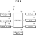
- FIG. 1 illustrates a control block diagram of an X-ray imaging apparatus, according to an embodiment of the present disclosure
- FIG. 2 is an exterior view illustrating a configuration in which an X-ray imaging apparatus is implemented in a ceiling type, according to an embodiment of the present disclosure
- FIG. 3 is an exterior view illustrating a configuration in which an X-ray imaging apparatus is implemented in a mobile type according to an embodiment of the present disclosure.
- an X-ray imaging apparatus 100 in accordance with an embodiment may include an X-ray source 110 for generating and irradiating an X-ray to a subject, a photographing device 120 equipped in the X-ray source 110 for capturing a camera image, a source driver 130 for moving the X-ray source 110, a controller 140 for analyzing the camera image captured by the photographing device 120 to determine thickness of the subject and controlling a condition for X-ray radiation based on the thickness of the subject, a display 151 for displaying a screen to provide information about X-raying for the user, a screen to guide a control command input by the user, a camera image or X-ray image captured by the photographing device 120, etc., an input 152 for receiving a control command from the user, a storage 170 for storing X-ray irradiation conditions per thickness of a subject, and a communication device 180 for exchanging data in communication with an X-ray detector 200 or other external devices.
- FIG. 2 illustrates an example of an X-ray imaging apparatus, which is a ceiling type X-ray imaging apparatus with an X-ray source attached to the ceiling of an examination room.
- a guide rail 30 may be installed on the ceiling of the examination room where the X-ray imaging apparatus 100 is placed, and the X-ray source 110 linked to a moving carriage 40 that moves along the guide rail 30 may be moved to a position corresponding to the subject.
- the moving carriage 40 and the X-ray source 110 may be linked through a foldable post frame 50, and the altitude of the X-ray source 110 may be adjusted by shortening or extending the length of the post frame 50.
- a rotary joint 60 is arranged between the X-ray source 110 and the post frame 50.
- the rotary joint 60 may include a first rotary joint 61 coupled to the post frame 50 and a second rotary joint 62 coupled to the X-ray source 110.
- the first rotary joint 61 may be rotated in a fourth direction D4 and the second rotary joint 62 may be rotated in a fifth direction D5.
- a tilt angle of the X-ray source 110 may be adjusted.
- the posture of the X-ray source 110 may be defined by a rotation angle in the fourth direction D4 or a tilt angle in the fifth angle D5.
- the source driver 130 may include a plurality of motors to provide power required to move the X-ray source 110 straight or rotate the X-ray source 110.
- the controller 140 may adjust the position or posture of the X-ray source 110 by controlling the source driver 130.
- the X-ray source 110 may be equipped with an X-ray tube for generating an X-ray and a collimator for adjusting an irradiation area of an X-ray generated by the X-ray tube. Accordingly, the X-ray source 110 may also be called a Tube Head Unit (THU).
- TNU Tube Head Unit
- the photographing device 120 for capturing a camera image may also be equipped in the X-ray source 110. Where to install the photographing device 120 will be described later.
- the X-ray imaging apparatus 100 may include a workstation 150 located a distance away from the X-ray source 110 for providing a user interface.
- the X-ray source 110 and the workstation 150 may have a blackout curtain B arranged in between to prevent a radiological technologist, a doctor, or the user from being unnecessarily exposed to radiation.
- the workstation 150 may be equipped with the input 152 for receiving a control command from the user and a display 151 for displaying various kinds of information and images.
- the input 152 may receive commands to control an X-raying protocol, an X-ray irradiation condition, an X-ray irradiation timing, a position or posture of the X-ray source 110, etc., or command for capturing camera images.
- the input 152 may include a keyboard, a mouse, a touch screen, a microphone, etc.
- the display 151 may display a screen to guide the user in selecting an X-raying protocol, a screen to guide the user in setting an X-ray irradiation condition, a screen to receive a control command for X-ray irradiation timing or positioning of the X-ray source 110, etc. Furthermore, the display 151 may display a screen to show a current state of workflows for X-raying, or display a camera image captured by the photographing device 120, or display an X-ray image of the subject.
- the controller 140 may control X-ray irradiation timing, X-ray irradiation conditions, etc., according to a command entered by the user, and create a medical X-ray image using data received from the X-ray detector 200.
- the controller 140 may also control a position or posture of an install portion 14, 24 in which the X-ray source 110 or the X-ray detector 200 is installed, according to a X-raying protocol and a position of a subject P.
- the controller 140 may include a memory storing a program for carrying out the aforementioned operations and the following operations, and a processor for executing the program, and may be equipped in the workstation 150.
- the controller 140 may include a single processor or multiple processors, and in the latter case, the multiple processors may be integrated in a single chip or may be physically separated.
- the controller 140 includes the multiple processors
- some of the multiple processors may be included in the workstation 150, and some others in a sub-user interface 80 equipped in the X-ray source 110, the moving carriage 40, or other device.
- the processor(s) included in the workstation 150 may perform control, such as image processing to create an X-ray image
- the processor(s) included in the sub-user interface 80 or the moving carriage 40 may perform control over the operation or movement of the X-ray source 110 or the X-ray detector 200.
- the X-ray imaging apparatus 100 may be connected to the X-ray detector 200 or an external device (e.g., an external server for storing and managing medical images, another medical device and a portable terminal such as a tablet Personal Computer (PC) and a wearable device) for exchanging data through the communication device 180.
- an external device e.g., an external server for storing and managing medical images, another medical device and a portable terminal such as a tablet Personal Computer (PC) and a wearable device
- PC Personal Computer
- the communication device 180 may include one or more components that enable communication with an external device, for example, at least one of a short-range communication module, a wired communication module, and a wireless communication module.
- the communication device 180 may also receive a control signal from the external device and forward the control signal for the controller 140 to control the X-ray imaging apparatus 100 according to the control signal.
- the X-ray detector 200 may be implemented as a fixed type of X-ray detector fixed on a stand 20 or a table 10, or may detachably equipped in the install portion 14, 24.
- the X-ray detector 300 may be implemented as a portable X-ray detector available at any place.
- the portable X-ray detector may further be classified into a wired type and a wireless type depending on the data transfer method or the power supplying method.
- the X-ray detector 200 may or may not be included as an element of the X-ray imaging apparatus 100. In the latter case, the X-ray detector 200 may be registered in the X-ray imaging apparatus 100 by the user.
- the X-ray detector 200 may be connected to the controller 140 through the communication device 180 for receiving a control signal or sending image data.
- the sub-user interface 80 may be arranged on one side of the X-ray source 110, and may perform a part or all of the functions performed by the input 152 and the display 151 of the workstation 150.
- controller 140 and the communication device 180 may be included in the sub-user interface 80 arranged on the X-ray source 110.
- the X-ray imaging apparatus 100 may be implemented not only in the ceiling type but also in a mobile type.
- a main body 101 connected to the X-ray source 110 may be freely movable and an arm 103 connecting the X-ray source 110 and the main body 101 is also be able to rotate and make linear motions, enabling the X-ray source 110 to be freely moved in the three dimensional (3D) space.
- the main body 101 may have a keeper 105 for keeping the X-ray detector 200. Furthermore, the keeper 105 may also have a charging terminal provided therein to charge the X-ray detector 200, so it is possible for the keeper 105 to be able to keep and charge the X-ray detector 200.
- the input 152, the display 151, the controller 140, and the communication device 180 may be provided in the main body 101, and image data acquired by the X-ray detector 200 may be sent to the main body 101 to go through image processing and then displayed on the display 151 or sent to the external device through the communication device 180.
- the controller 140 and the communication device 180 may be provided separately from the main body 101, or some of the components of the controller 140 and the communication device 180 may be provided in the main body 101.
- FIG. 4 illustrates an exterior view of a portable X-ray detector available for an X-ray imaging apparatus according to an embodiment of the present disclosure
- the X-ray detector 200 available for the X-ray imaging apparatus 100 may be implemented in a portable type.
- the X-ray detector 200 may include a battery to supply power and thus, operate wirelessly, or as shown in FIG. 4 , may have a charging port 201 connected to a separate power supplier via a cable C.
- a detecting device for detecting and converting an X-ray to image data
- a memory for temporarily or non-temporarily storing the image data
- a communication module for receiving a control signal from the X-ray imaging apparatus 100 or transmitting image data to the X-ray imaging apparatus 100
- a battery for storing image data
- the memory may store image correction information of the detector and unique identification information of the X-ray detector 200, and may send the identification information while communicating with the X-ray imaging apparatus 100.
- the X-ray detector 200 may be installed in the install portion 14 of the imaging table 10 or in the installation portion 24 of the imaging stand 20, but it is also possible to perform X-ray imaging without installing the X-ray detector 200 in the install portion 14, 24 depending on a condition or a portion to be photographed of the subject.
- X-raying may be performed by irradiating an X-ray to a portion to be photographed (or called an imaging portion) while the X-ray detector 200 is located behind the imaging portion.
- a mode in which X-raying is performed with the X-ray detector 200 installed in the install portion 14 of the imaging table 10 is called a table mode; a mode in which X-raying is performed with the X-ray detector 200 installed in the install portion 24 of the imaging stand 20 is called a stand mode; a mode in which X-raying is performed with the X-ray detector 200 not installed in the install portion 14, 24 but located behind an imaging portion of the subject is called a portable mode.
- An X-ray irradiation condition may be determined depending on the feature of the subject or the imaging environment.
- the X-ray irradiation condition may include at least one of exposure parameters, such as a tube voltage (Kvp), a tube current (mA), exposure time (s), a filter type and thickness, a target material of anode, focal spot size, etc., and scatter parameters, such as a grid angle or center position, field of view (FOV), etc.
- exposure parameters such as a tube voltage (Kvp), a tube current (mA), exposure time (s), a filter type and thickness, a target material of anode, focal spot size, etc.
- scatter parameters such as a grid angle or center position, field of view (FOV), etc.
- the thickness of the subject may be considered.
- the controller 140 may obtain the thickness of the subject in a way of subtracting the Source to Object Distance (SOD) from the Source to Image Distance (SID).
- SOD Source to Object Distance
- SID Source to Image Distance
- the X-ray imaging apparatus 100 may obtain information about thickness of the subject and information about the portion to be X-rayed or the position and posture of the X-ray detector 200 from a camera image captured by the photographing device 120.
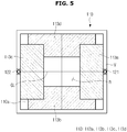
- FIG. 5 illustrates a front view of an X-ray source of an X-ray imaging apparatus, according to an embodiment of the present disclosure.
- the front view as herein used refers to a view of the X-ray source viewed from a direction in which an X-ray is irradiated.
- the X-ray source 110 may include the X-ray tube for generating an X-ray and the collimator 113 for adjusting an irradiation range of the X-ray.
- the collimator 113 is located in front of the X-ray tube, i.e., in a direction in which the X-ray is irradiated.
- the collimator 113 may include a plurality of movable blades 113a, 113b, 113c, 113d, and the blades may be made of a material with high bandgap to absorb the X-ray.
- the X-ray irradiation range may be adjusted by moving the blades, and the X-ray is irradiated through a slot R formed by the plurality of blades.
- the collimator 113 may further include a motor for providing driving force to the respective blades. Each of the plurality of blades may be independently moved.
- the controller 140 may calculate an amount of movement of each blade to irradiate an X-ray to a set irradiation region, and send a control signal to the collimator 113 to move the blade as much as the calculated amount of movement.
- the photographing device 120 may be provided in an area adjacent to the collimator 113.
- the photographing device 120 may take a real image.
- the real image taken by the photographing device 120 may be a moving image or a still image. While a moving image is being taken, a still image may be captured at a particular point of time.
- the image taken by the X-ray source 110 is classified as an X-ray image
- the image taken by the photographing device 120 is classified as a camera image.
- the camera image may or may not include the subject.
- the camera image may be taken when the subject P is located in front of the X-ray detector 200, or may be taken when the subject P is not present.
- the camera image may or may not include the user.
- the user as herein used may be an entity that performs X-raying on the subject by operating the X-ray apparatus 100, such as a radiological technologist, a doctor, a nurse, etc.
- the photographing device 120 may be placed in a position where a portion to be X-rayed of the subject may be photographed. For example, it may be installed to be directed toward the same direction in which the X-ray source 110 irradiates an X-ray. Once the photographing device 120 is installed in the X-ray source 110, an offset between an area appearing in the X-ray image and an area appearing in the camera image becomes small, so it may be easier to perform X-ray image related setting by using the camera image.
- the position to install the photographing device 120 may be determined within a range that may give little influence to X-raying while minimize the offset between the area appearing in the X-ray image and the area appearing in the camera image.
- a housing 110a is formed in front of the collimator 113 and may be made of a material such as a transparent resin or glass to minimize its influence to an X-ray irradiated from the X-ray tube 111.
- cross guide lines GL may be marked on the housing 110a.
- a collimator lamp equipped in the X-ray source 110 irradiates a visible ray into an X-ray irradiation area
- the shadow of the guide line GL may be projected down on the center of the X-ray irradiation area, enabling the user to intuitively know of the position of the X-ray irradiation area from the shadow.
- the photographing device 120 may be installed inside or outside the housing 110a. If the photographing device 120 is installed outside the housing 110a, it may be mounted in a bezel V formed on the perimeter of the housing 110a. It is, however, not limited thereto, and the photographing device 120 may be installed at any place that allows taking an image including the subject or the user.
- the photographing device 120 may include a 3D camera for acquiring 3D information.
- the photographing device 120 may include a stereo camera or a depth camera to acquire depth information of the object present in a scene.
- cameras 121, 122 may be equipped on the front left and right sides of the X-ray source 110.
- the controller 140 may perform stereo matching with camera images captured by the left and right cameras 122, 121, and thus calculate the depth information of the object, which appears in the camera images.
- the cameras 121, 122 shown in FIG. 5 are only an example available for the X-ray imaging apparatus 100, and it is also possible to have three or more cameras to obtain multi-view images for more accurate calculation of depth information.
- the photographing device 120 may include an infrared sensor and a color camera to acquire the depth information of an object.
- an infrared sensor may be installed on the front left and right sides of the X-ray source 110, and an infrared sensor may be installed between the two cameras.
- the depth camera may acquire the depth information using a Time-of-Flight (TOF) technology.
- TOF Time-of-Flight
- the TOF technology is to measure a distance by calculating time for an infrared signal to reflect off a subject and return.
- the controller 140 may obtain thickness information of the subject (P) from a camera image including depth information of the subject. Specifically, the controller 140 may detect a plurality of indicators from the camera image. One of the plurality of indicators may be located on the front face of an X-raying portion of the subject P, and the other may be located at a distance of the thickness of the X-raying portion away from the front face.
- the front face herein refers to a surface on which the X-ray is incident. Accordingly, the controller 140 may calculate the thickness of the subject P based on the distance between the plurality of indicators.
- the plurality of indicators may include both hands of the user.
- the user may put one hand on the front face of the X-raying portion of the subject while putting the other hand at a distance of the thickness of the X-raying portion away from the front face.
- An example of using both hands of the user as the plurality of indicators will now be described in detail.
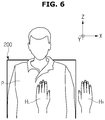
- FIG. 6 illustrates positions of the user's hands viewed from the front of a portion to be X-rayed to obtain thickness information of a subject
- FIG. 7 illustraes positions of the user's hands viewed from a side of the portion to be X-rayed to obtain thickness information of the subject.
- the X-ray detector 200 is located in the back of the portion to be X-rayed (or called the X-raying portion) of the subject P in the portable mode to perform X-raying.
- the user places one hand H L in front of the X-raying portion of the subject P while placing the other hand H R at the same point as the X-ray detector 200 on the Y-axis.
- the distance between the hand H L placed in front of the X-raying portion and the X-ray detector 200 is equal to the distance between the hand H L and the other hand H R .
- the distance on the Y-axis between the hands H L , H R of the user may be assumed to be equal to or almost similar to the thickness D of the X-raying portion of the subject P.
- the thickness of the subject may be measured without extra equipment or tools by using the hands of the user appearing in a camera image.
- the X-ray detector 200 is located in the back of the X-raying portion in the embodiment of FIGS. 6 and 7 , it is possible to capture a camera image to acquire the thickness information of the X-raying portion before placing the X-ray detector 200. Even in this case, one hand H L of the user may be placed in front of the X-raying portion of the subject P and the other hand H R may be placed at the same point as the X-ray detector 200 on the Y-axis.
- the photographing device 120 may have been taking camera images before the hands H L , H R of the user are placed a distance of the thickness D of the subject away from each other.
- the user may manipulate the input 152 from when beginning preparing for X-ray imaging and enter a command to capture a camera image, and the photographing device 120 may start taking a moving image according to the command. If a preset event occurs during the capturing of a camera image, the thickness D information of the subject may be obtained by calculating a distance between the hands of the user from a camera image captured at the point when the event occurs. This will now be described with reference to FIG. 8 .
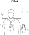
- FIG. 8 illustrates an example of a gesture functioning as a specific event to obtain thickness information of a subject.
- the controller 140 may determine that a preset event has occurred and calculate the thickness D of the subject using the positions of the hands H L , H R at the point when the event has occurred.
- gesture of the user spreading one hand H L is registered in advance in the example of FG. 8
- embodiments of the present disclosure are not limited thereto but any gesture that may be recognized by an image recognition algorithm may be an event to indicate time to measure the thickness of the subject.
- the controller 140 may recognize the user's hand appearing in the camera image by means of an object recognition algorithm and recognize a gesture made by the user's hand using a gesture recognition algorithm. If the recognized gesture corresponds to a pre-registered gesture, it is considered that the event to measure the thickness D of the subject has occurred, and subsequently, the thickness D of the subject may be calculated using the camera image captured at the time the event has occurred. Since every portion of the subject may have different thickness, to be precise, the thickness of the X-raying portion may be calculated.
- the controller 140 may control the photographing device 120 to capture a still image at the point when the event occurs, and calculate the thickness D of the X-raying portion using the captured still image.
- the photographing device 120 may include a 3D camera that may acquire depth information of an object appearing in a camera image, so the controller 140 may obtain depth information of each of the hands H L , H R appearing in the camera image.
- the depth information as herein used may refer to a distance between the photographing device 120 and either hand H L , H R .
- the controller 140 may use an object recognition algorithm to recognize each of the hands H L , H R appearing in the camera image and calculate the depth of either hand H L , H R .
- the depth of the hand H L placed in front of the X-raying portion may be estimated to correspond to the SOD, and the depth of the hand H R placed in the back of the X-raying portion may be estimated to correspond to the SID.
- the controller 140 may obtain the thickness D of the X-raying portion from the difference in thickness between the hand H L placed in front of the X-raying portion and the hand H R placed in the back of the X-raying portion. That is, the distance between the hands H L , H R appearing in the camera image may be estimated to be the thickness D of the X-raying portion.
- the X-ray irradiation condition may vary by the thickness D of the X-raying portion. Accordingly, the controller 140 may control the X-ray irradiation condition based on the thickness information obtained from the camera image and the X-ray irradiation conditions by thickness of the X-raying portion may be stored in the storage 170 in advance.
- the X-ray irradiation condition may vary by X-raying protocol as well. Specifically, the X-raying portion may vary by imaging protocol, and a suitable X-ray irradiation condition may vary by X-raying portion.
- the X-raying protocol may be determined based on the X-raying portion, the posture of the object, etc., and may include, for example, the whole body Anterior-Posterior (AP), the whole body Posterior-Anterior (PA), the whole body LAT. Even for the chest, there may be imaging protocols for capturing images in the AP, PA, LAT methods, and for long bones such as legs, there may be imaging protocols for capturing images in the AP, PA, LAT methods. Furthermore, Abdomen Erect may also be included in the imaging protocol.
- AP Anterior-Posterior
- PA Posterior-Anterior
- Abdomen Erect may also be included in the imaging protocol.
- the controller 140 may recognize an X-raying portion and posture from a camera image by applying an object recognition algorithm, and may automatically set an X-raying protocol based on the result of recognition. In this regard, the controller 140 may recognize a portion where there are the user's hands H L , H R as an X-raying portion.
- the controller 140 may also automatically set an X-ray irradiation condition based on the thickness of the X-raying portion and the X-raying protocol. Information about the X-ray irradiation condition based on the thickness of the X-raying portion and the X-raying protocol may be stored in the storage 170 in advance.
- FIG. 9 illustrates how to control a position of an X-ray source using the position of the user's hand, according to an embodiment of the present disclosure
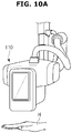
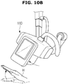
- FIGS. 10A and 10B illustrate an example of controlling an angle of an X-ray source using an angle of the user's hand, according to an embodiment of the present disclosure.
- a camera image captured by the photographing device 120 may be used.
- the controller 140 may control the position of the X-ray source 110 by using a camera image in which a hand H of the user placed in the X-raying portion appears.
- the camera image used for measuring the thickness D of the X-raying portion may be used.
- the sequence of measuring the thickness and controlling the position of the X-ray source 110 is not fixed.
- the thickness may be measured first or the position of the X-ray source 110 may be controlled first.
- the controller 140 may recognize the hand H of the user from the camera image and detect the position of the recognized hand H. For more precise position control, a center Hc of the hand H may be recognized and the position of the hand's center Hc may be detected. Since the photographing device 120 includes a 3D camera, the position of the hand's center Hc may be calculated in 3D coordinates in a camera coordinate system.
- the controller 140 may calculate an amount of control to correspond the position of the X-ray tube to the position of the hand's center Hc based on the relationship between the camera coordinate system and a global coordinate system in real space and a relative position of the X-ray tube and the photographing device 120.
- the controller 140 may send a control signal corresponding to the calculated amount of control to the source driver 130 to control the position of the X-ray source 110 by moving or rotating the moving carriage 40, the post frame 50, or the rotary joint 60.
- the user may rotate the angle of the hand H to correspond to the angle of the X-raying portion, and the controller 140 may detect a rotation angle of the hand H from the camera image and use the rotation angle to control the posture of the X-ray source 110.
- the angle of the hand placed in front or back of the X-raying portion may correspond to the angle of the X-raying portion.
- the angle as herein used refers to an angle from the ground.
- the controller 140 may detect an angle of the hand H from a camera image including 3D information, and calculate an amount of control to correspond the posture of the X-ray source 110 to the detected angle.
- the controller 140 may control a rotation angle of the X-ray source 110 in the fourth direction D4 or in the fifth D5 direction by sending a control signal corresponding to the calculated amount of control to the source driver 130 and rotating the rotary joint 60.
- the X-ray imaging apparatus 110 may not be restricted to the sequence of calculation of the thickness of the X-raying portion and control of the position and posture of the X-ray source 110, but no matter which operation is performed first, the X-ray source 110 should be located at a point to capture a camera image of the X-raying portion.
- control method of an X-ray imaging apparatus An embodiment of a control method of an X-ray imaging apparatus will now be described.
- the X-ray imaging apparatus 100 may be used. Accordingly, what are described in connection with FIGS. 1 to 10 may be equally applied to the control method of the X-ray imaging apparatus.
- FIG. 11 is a flowchart illustrating a control method of an X-ray imaging apparatus, according to an embodiment of the present disclosure.
- a camera image is captured using the photographing device 120, in 410.
- the photographing device 120 may include a 3D camera for acquiring depth information of a subject.
- the user places one hand H L in front of the X-raying portion of the subject P while placing the other hand H R at the same point as the X-ray detector 200 on the Y-axis.
- the distance between the hand H L placed in front of the X-raying portion and the X-ray detector 200 is equal to the distance between the hand H L and the other hand H R .
- a distance between the hands of the user is calculated from a camera image, in 411. Since the photographing device 120 includes the 3D camera that may acquire depth information of an object appearing in the camera image, the controller 140 may obtain depth information of each of the hands H L , H R appearing in the camera image.
- the depth information as herein used may refer to a distance between the photographing device 120 and either hand H L , H R .
- the controller 140 uses an object recognition algorithm to recognize each of the hands H L , H R appearing in the camera image and calculates the depth of either hand H L , H R .
- the controller 140 may obtain the distance between the hands H L , H R appearing in the camera image from the difference in thickness between the hand H L placed in front of the X-raying portion and the hand H R placed in the back of the X-raying portion.
- the distance between the hands of the user is estimated as thickness of the subject, in 412, and based on the estimated thickness of the subject, X-ray irradiation condition is controlled, in 413.
- the thickness of the subject refers to the thickness of the X-raying portion.
- the X-ray irradiation condition may vary by thickness D of the X-raying portion. Accordingly, the controller 140 may control the X-ray irradiation condition based on the thickness information obtained from the camera image and the X-ray irradiation conditions by the X-raying portion may be stored in the storage 170 in advance.
- the X-ray irradiation condition may include at least one of exposure parameters, such as a tube voltage (Kvp), a tube current (mA), exposure time (s), a filter type and thickness, a target material of anode, focal spot size, etc., and scatter parameters, such as a grid angle or center position, field of view (FOV), etc.
- exposure parameters such as a tube voltage (Kvp), a tube current (mA), exposure time (s), a filter type and thickness, a target material of anode, focal spot size, etc.
- scatter parameters such as a grid angle or center position, field of view (FOV), etc.
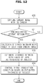
- FIG. 12 is a flowchart illustrating how to measure the thickness of an object if a preset event occurs in a control method of an X-ray imaging apparatus, according to an embodiment of the present disclosure.
- a camera image is captured using a 3D camera, in 420.
- the photographing device 120 including the 3D camera may have been taking camera images before the hands H L , H R of the user are placed a distance of the thickness D of the subject away from each other.
- the user may manipulate the input 152 from when beginning preparing for X-ray imaging and enter a command to capture a camera image, and the photographing device 120 may start taking a moving image according to the command.
- the thickness D information of the subject may be obtained by using a camera image captured at the point when the event occurs.
- Recognition of a pre-registered gesture may be set in advance as an event to measure the thickness of the subject.
- the controller 140 analyzes the camera image to determine whether a pre-registered gesture is recognized, in 421.
- the controller 140 may determine that a preset event has occurred. Specifically, the controller 140 may recognize the user's hand appearing in the camera image by means of an object recognition algorithm and recognize a gesture made by the user's hand using a gesture recognition algorithm. If the recognized gesture corresponds to the pre-registered gesture, it is considered that an event to measure the thickness D of the subject has occurred.
- a distance between the hands of the user is calculated from the camera image, in 422, and the distance between the hands of the user is estimated as the thickness of the subject, in 423.
- the controller 140 may control the photographing device 120 to capture a still image at the point when the event occurs, and calculate the distance between the hands from the captured still image.
- the X-ray irradiation condition is controlled based on the estimated thickness of the subject, in 424, and X-raying is performed.
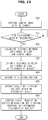
- FIG. 13 is a flowchart illustrating how to automatically recognize a portion to be X-rayed using a camera image in a control method of an X-ray imaging apparatus, according to an embodiment of the present disclosure.
- a camera image is captured using a 3D camera, in 430.
- the controller 140 analyzes the camera image to determine whether a pre-registered gesture is recognized, in 431.
- a distance between the hands of the user is calculated from the camera image, in 432, and the distance between the hands of the user is estimated as the thickness of the subject, in 433.
- An X-raying portion is recognized from the camera image, in 434.
- the controller 140 may apply an object recognition algorithm to recognize the X-raying portion from the camera image.
- the controller 140 may recognize a portion where there are the user's hands H L , H R as an X-raying portion.
- an X-raying protocol may be automatically set, in 435.
- the X-ray irradiation condition is controlled based on the set X-raying protocol and the estimated thickness of the subject, in 436, and X-raying is performed.
- Information about the X-ray irradiation condition based on the thickness of the X-raying portion and the X-raying protocol may be stored in the storage 170 in advance.
- FIG. 14 is a flowchart illustrating how to control a position and posture of an X-ray source using a camera image in a control method of an X-ray imaging apparatus, according to an embodiment of the present disclosure.
- a camera image is captured using a 3D camera, in 440.
- the controller 140 analyzes the camera image to determine whether a pre-registered gesture is recognized, in 441.
- a distance between the hands of the user is calculated from the camera image, in 442, and the distance between the hands of the user is estimated as the thickness of the subject, in 443.
- the controller 140 may recognize the hand H of the user from the camera image and detect a position of the center Hc of the recognized hand H, in 444. Since the photographing device 120 includes a 3D camera, the position of the hand's center Hc may be calculated in 3D space coordinates.
- the position of the X-ray source is controlled based on the detected center position of the hand, in 445.
- the controller 140 may calculate an amount of control to correspond the position of the X-ray tube to the position of the hand's center Hc based on the relationship between the camera coordinate system and a global coordinate system and a relative position of the X-ray tube and the photographing device 120.
- the controller 140 may send a control signal corresponding to the calculated amount of control to the source driver 130 to control the position of the X-ray source 110 by moving or rotating the moving carriage 40, the post frame 50, or the rotary joint 60.
- the controller 140 detects a rotation angle of the user's hand from the camera image, in 446.
- An angle of the hand placed in front or back of the X-raying portion may correspond to the angle of the X-raying portion.
- the angle as herein used refers to an angle from the ground.
- the controller 140 may detect an angle of the hand H from the camera image including the 3D information.
- the position of the X-ray source is controlled based on the detected rotation angle of the hand, in 447.
- the controller 140 may calculate an amount of control to correspond the posture of the X-ray source 110 to the detected angle.
- the controller 140 may control a rotation angle of the X-ray source 110 in the fourth direction D4 or in the fifth D5 direction by sending a control signal corresponding to the calculated amount of control to the source driver 130 and rotating the rotary joint 60.
- the X-ray irradiation condition is controlled based on the estimated thickness of the subject, in 448, and X-raying is performed.
- the control method of an X-ray imaging apparatus in an embodiment is not restricted to a sequence of thickness calculation of the X-raying portion, recognition of the X-raying portion, and control of the position and posture of the X-ray source 110.
- information about an X-raying portion, information about the thickness of the X-raying portion, information about the position to be X-rayed, information about an X-raying angle, or the like, which is required in setting an X-ray irradiation condition may be obtained by using the user's hand appearing in the camera image without using an extra marker, thereby easily obtaining more accurate information at low costs.
- a hand of the user may be photographed, and from the photographed image, information about a thickness of a subject, information about a photographed spot or information about a photographing angle may be easily obtained.
Landscapes
- Engineering & Computer Science (AREA)
- Health & Medical Sciences (AREA)
- Life Sciences & Earth Sciences (AREA)
- Medical Informatics (AREA)
- Physics & Mathematics (AREA)
- Molecular Biology (AREA)
- General Health & Medical Sciences (AREA)
- Biophysics (AREA)
- Public Health (AREA)
- Pathology (AREA)
- Veterinary Medicine (AREA)
- Biomedical Technology (AREA)
- Heart & Thoracic Surgery (AREA)
- High Energy & Nuclear Physics (AREA)
- Surgery (AREA)
- Animal Behavior & Ethology (AREA)
- Radiology & Medical Imaging (AREA)
- Nuclear Medicine, Radiotherapy & Molecular Imaging (AREA)
- Optics & Photonics (AREA)
- Theoretical Computer Science (AREA)
- General Physics & Mathematics (AREA)
- General Engineering & Computer Science (AREA)
- Multimedia (AREA)
- Human Computer Interaction (AREA)
- Computer Vision & Pattern Recognition (AREA)
- Electromagnetism (AREA)
- Spectroscopy & Molecular Physics (AREA)
- Signal Processing (AREA)
- Psychiatry (AREA)
- Social Psychology (AREA)
- Apparatus For Radiation Diagnosis (AREA)
Applications Claiming Priority (1)
| Application Number | Priority Date | Filing Date | Title |
|---|---|---|---|
| KR1020170010475A KR102713073B1 (ko) | 2017-01-23 | 2017-01-23 | 엑스선 영상 장치 및 그 제어 방법 |
Publications (2)
| Publication Number | Publication Date |
|---|---|
| EP3351176A1 true EP3351176A1 (de) | 2018-07-25 |
| EP3351176B1 EP3351176B1 (de) | 2021-05-05 |
Family
ID=60954962
Family Applications (1)
| Application Number | Title | Priority Date | Filing Date |
|---|---|---|---|
| EP18151220.3A Active EP3351176B1 (de) | 2017-01-23 | 2018-01-11 | Röntgenbildgebungsvorrichtung und steuerungsverfahren dafür |
Country Status (3)
| Country | Link |
|---|---|
| US (1) | US10849589B2 (de) |
| EP (1) | EP3351176B1 (de) |
| KR (1) | KR102713073B1 (de) |
Cited By (4)
| Publication number | Priority date | Publication date | Assignee | Title |
|---|---|---|---|---|
| EP3689241A1 (de) * | 2019-02-01 | 2020-08-05 | Samsung Electronics Co., Ltd. | Röntgenbildverarbeitungsverfahren und röntgenbildverarbeitungsvorrichtung |
| CN112472110A (zh) * | 2019-09-12 | 2021-03-12 | 通用电气精准医疗有限责任公司 | X射线成像系统及方法 |
| US11540785B2 (en) | 2019-01-25 | 2023-01-03 | Samsung Electronics Co., Ltd. | X-ray image processing method and x-ray image processing apparatus |
| US12499713B2 (en) * | 2023-06-08 | 2025-12-16 | KUB Technologies, Inc. | System and method for hand gesture control of cabinet x-ray systems |
Families Citing this family (8)
| Publication number | Priority date | Publication date | Assignee | Title |
|---|---|---|---|---|
| KR102592905B1 (ko) * | 2016-12-21 | 2023-10-23 | 삼성전자주식회사 | 엑스선 영상 촬영 장치 및 제어방법 |
| CN110946597B (zh) * | 2018-09-27 | 2023-09-26 | 上海西门子医疗器械有限公司 | X射线摄影设备和方法 |
| JP7350519B2 (ja) * | 2019-05-29 | 2023-09-26 | キヤノン株式会社 | 放射線撮影システム、放射線撮影制御装置及びその制御方法、並びに、プログラム |
| EP4218583A4 (de) * | 2020-09-25 | 2024-03-06 | FUJIFILM Corporation | Einstellvorrichtung, einstellverfahren und einstellprogramm |
| JP2024052321A (ja) * | 2022-09-30 | 2024-04-11 | 富士フイルム株式会社 | 情報処理装置、情報処理方法及び情報処理プログラム |
| JP2024067064A (ja) * | 2022-11-04 | 2024-05-17 | キヤノン株式会社 | 情報処理装置、放射線撮影システム、情報処理方法、及びプログラム |
| JP2025133574A (ja) * | 2024-03-01 | 2025-09-11 | 富士フイルム株式会社 | 情報処理装置、情報処理方法、及び情報処理プログラム |
| KR102824459B1 (ko) * | 2024-12-05 | 2025-06-24 | (주)시닉스레이 | 방사선 조사량을 최적화할 수 있는 X-ray 장치 및 이를 이용한 X-ray 촬영방법 |
Citations (5)
| Publication number | Priority date | Publication date | Assignee | Title |
|---|---|---|---|---|
| US20060269046A1 (en) * | 2005-04-29 | 2006-11-30 | Thomas Schmitt | X-ray system including an assigned solid state detector, and a method for acquiring and displaying an X-ray image |
| EP2727535A1 (de) * | 2012-11-06 | 2014-05-07 | Samsung Electronics Co., Ltd | Strahlungsabbildungsvorrichtung und Steuerverfahren dafür |
| US20140355735A1 (en) * | 2013-05-31 | 2014-12-04 | Samsung Electronics Co., Ltd. | X-ray imaging apparatus and control method thereof |
| JP2016209548A (ja) * | 2015-05-11 | 2016-12-15 | 富士フイルム株式会社 | 放射線画像撮影装置、並びに放射線画像撮影装置の制御方法およびプログラム |
| WO2017111464A1 (en) * | 2015-12-22 | 2017-06-29 | Samsung Electronics Co., Ltd. | X-ray imaging apparatus, control method for the same, and x-ray detector |
Family Cites Families (26)
| Publication number | Priority date | Publication date | Assignee | Title |
|---|---|---|---|---|
| US5323443A (en) * | 1992-07-24 | 1994-06-21 | Banning G. Lary | X-ray film marking system |
| JPH06269444A (ja) * | 1993-03-24 | 1994-09-27 | Fujitsu Ltd | 放射線三次元画像の生成方法 |
| US6447163B1 (en) * | 1999-09-30 | 2002-09-10 | Siemens Corporate Research, Inc. | Method for aligning and superimposing X-ray and video images |
| FR2846503B1 (fr) * | 2002-10-29 | 2005-03-25 | Ge Med Sys Global Tech Co Llc | Procede de determination des parametres optimaux d'une acquisition de radiographie |
| JP4612796B2 (ja) * | 2004-01-30 | 2011-01-12 | キヤノン株式会社 | X線撮影画像表示制御装置及び方法並びにx線撮影システム |
| JP4487180B2 (ja) * | 2004-03-18 | 2010-06-23 | ソニー株式会社 | 情報生成装置及び情報生成方法 |
| US8116401B2 (en) | 2005-05-26 | 2012-02-14 | Broadcom Corporation | Method and system for digital spur cancellation |
| US8203132B2 (en) * | 2005-09-08 | 2012-06-19 | Carestream Health, Inc. | Apparatus and method for imaging ionizing radiation |
| US7495226B2 (en) * | 2006-05-26 | 2009-02-24 | Carestream Health, Inc. | Compact and durable encasement for a digital radiography detector |
| DE102008035412A1 (de) * | 2008-07-29 | 2010-02-04 | Sirona Dental Systems Gmbh | Verfahren zur Erstellung einer dentalen 3D-Röntgenaufnahme und Röntgengerät hierfür |
| JP2011019707A (ja) * | 2009-07-15 | 2011-02-03 | Fujifilm Corp | X線撮影装置、x線撮影装置の制御方法、及びプログラム |
| JP5701306B2 (ja) * | 2009-10-20 | 2015-04-15 | イムリス インク. | マーカーを使用する画像システム |
| US8550709B2 (en) * | 2009-11-09 | 2013-10-08 | Fujifilm Corporation | Imaging area specifying apparatus, radiographic system, imaging area specifying method, radiographic apparatus, and imaging table |
| JP5479069B2 (ja) * | 2009-12-17 | 2014-04-23 | 株式会社東芝 | X線ct装置及びx線ct装置の制御方法 |
| KR20130010425A (ko) * | 2011-07-18 | 2013-01-28 | 삼성전자주식회사 | 엑스선 장치 및 이를 이용한 엑스선 조사영역 조절방법 |
| US20130279661A1 (en) * | 2012-04-19 | 2013-10-24 | Canon Kabushiki Kaisha | Radiant ray generation control apparatus, radiation imaging system, and method for controlling the same |
| KR101429068B1 (ko) * | 2012-12-05 | 2014-08-13 | 삼성전자 주식회사 | 엑스선 영상 장치 및 그 제어방법 |
| WO2014098250A1 (ja) * | 2012-12-21 | 2014-06-26 | 株式会社 東芝 | X線診断装置 |
| WO2014167901A1 (ja) * | 2013-04-08 | 2014-10-16 | コニカミノルタ株式会社 | 診断提供用医用画像システム及び一般撮影用の診断提供用医用画像システムにタルボ撮影装置系を導入する方法 |
| DE102013226242A1 (de) * | 2013-12-17 | 2015-06-18 | Siemens Aktiengesellschaft | Einstellung eines Aufnahmebereichs |
| DE102014210897B4 (de) * | 2014-06-06 | 2022-01-13 | Siemens Healthcare Gmbh | Verfahren und Vorrichtung zur Strahlerpositionierung |
| KR102326968B1 (ko) * | 2014-08-29 | 2021-11-17 | (주)바텍이우홀딩스 | 맘모그래피 시스템 및 맘모그래피 촬영 방법 |
| JP6305890B2 (ja) * | 2014-09-22 | 2018-04-04 | 富士フイルム株式会社 | 電子カセッテシステムおよび電子カセッテ |
| US10338238B2 (en) * | 2014-11-28 | 2019-07-02 | Samsung Electronics Co., Ltd. | X-ray detector and X-ray imaging apparatus having the same |
| KR102335167B1 (ko) * | 2015-03-17 | 2021-12-03 | 삼성전자주식회사 | 영상 촬영 장치 및 이의 촬영 방법 |
| US10925555B2 (en) * | 2015-05-11 | 2021-02-23 | Fujifilm Corporation | Radiation imaging apparatus, and method and program for controlling radiation imaging apparatus |
-
2017
- 2017-01-23 KR KR1020170010475A patent/KR102713073B1/ko active Active
-
2018
- 2018-01-11 EP EP18151220.3A patent/EP3351176B1/de active Active
- 2018-01-12 US US15/870,409 patent/US10849589B2/en active Active
Patent Citations (5)
| Publication number | Priority date | Publication date | Assignee | Title |
|---|---|---|---|---|
| US20060269046A1 (en) * | 2005-04-29 | 2006-11-30 | Thomas Schmitt | X-ray system including an assigned solid state detector, and a method for acquiring and displaying an X-ray image |
| EP2727535A1 (de) * | 2012-11-06 | 2014-05-07 | Samsung Electronics Co., Ltd | Strahlungsabbildungsvorrichtung und Steuerverfahren dafür |
| US20140355735A1 (en) * | 2013-05-31 | 2014-12-04 | Samsung Electronics Co., Ltd. | X-ray imaging apparatus and control method thereof |
| JP2016209548A (ja) * | 2015-05-11 | 2016-12-15 | 富士フイルム株式会社 | 放射線画像撮影装置、並びに放射線画像撮影装置の制御方法およびプログラム |
| WO2017111464A1 (en) * | 2015-12-22 | 2017-06-29 | Samsung Electronics Co., Ltd. | X-ray imaging apparatus, control method for the same, and x-ray detector |
Cited By (5)
| Publication number | Priority date | Publication date | Assignee | Title |
|---|---|---|---|---|
| US11540785B2 (en) | 2019-01-25 | 2023-01-03 | Samsung Electronics Co., Ltd. | X-ray image processing method and x-ray image processing apparatus |
| EP3689241A1 (de) * | 2019-02-01 | 2020-08-05 | Samsung Electronics Co., Ltd. | Röntgenbildverarbeitungsverfahren und röntgenbildverarbeitungsvorrichtung |
| US11373308B2 (en) | 2019-02-01 | 2022-06-28 | Samsung Electronics Co., Ltd. | X-ray image processing method and X-ray image processing apparatus |
| CN112472110A (zh) * | 2019-09-12 | 2021-03-12 | 通用电气精准医疗有限责任公司 | X射线成像系统及方法 |
| US12499713B2 (en) * | 2023-06-08 | 2025-12-16 | KUB Technologies, Inc. | System and method for hand gesture control of cabinet x-ray systems |
Also Published As
| Publication number | Publication date |
|---|---|
| US20180206810A1 (en) | 2018-07-26 |
| KR20180086709A (ko) | 2018-08-01 |
| US10849589B2 (en) | 2020-12-01 |
| EP3351176B1 (de) | 2021-05-05 |
| KR102713073B1 (ko) | 2024-10-07 |
Similar Documents
| Publication | Publication Date | Title |
|---|---|---|
| EP3351176B1 (de) | Röntgenbildgebungsvorrichtung und steuerungsverfahren dafür | |
| CN104684483B (zh) | 快速帧率无线成像 | |
| EP3359043B1 (de) | Röntgenbildgebungsvorrichtung, steuerungsverfahren dafür und röntgendetektor | |
| EP3453330B1 (de) | Virtuelles positionierungsbild zur verwendung bei der bilderzeugung | |
| US10772576B2 (en) | X-ray imaging apparatus and control method thereof | |
| KR101429068B1 (ko) | 엑스선 영상 장치 및 그 제어방법 | |
| US10806412B2 (en) | Radiography system and method for operating radiography system | |
| CN102917646B (zh) | 用于移动式射线摄影术系统的管对准 | |
| CN100421624C (zh) | X射线诊断装置 | |
| EP3967234B1 (de) | Positionierungsführungssystem für röntgenuntersuchungen | |
| KR20170083338A (ko) | 엑스선 영상 장치 및 그 제어 방법 | |
| US11207048B2 (en) | X-ray image capturing apparatus and method of controlling the same | |
| US10702224B1 (en) | Positioning guidance system For X-ray exams | |
| US12324691B2 (en) | Cone beam computed tomography centering with augmented reality | |
| EP4505944B1 (de) | Verfahren und vorrichtung zur bestimmung des zieldetektionsbereichs einer ionisationskammer und speichermedium | |
| US11627925B2 (en) | X-ray imaging system and method for dental x-ray imaging | |
| KR20190037487A (ko) | 엑스선 촬영 장치 및 디텍터의 장착 위치 판단 방법 | |
| KR20140072837A (ko) | 엑스선 영상 장치 및 그 제어방법 | |
| WO2025029290A1 (en) | Tracking and positioning for digital radiography | |
| KR102407494B1 (ko) | 엑스선 영상 장치 및 그 제어 방법 | |
| TW201542173A (zh) | 結合深度攝影機之診療設備準直儀自動調節裝置及方法 |
Legal Events
| Date | Code | Title | Description |
|---|---|---|---|
| PUAI | Public reference made under article 153(3) epc to a published international application that has entered the european phase |
Free format text: ORIGINAL CODE: 0009012 |
|
| STAA | Information on the status of an ep patent application or granted ep patent |
Free format text: STATUS: THE APPLICATION HAS BEEN PUBLISHED |
|
| AK | Designated contracting states |
Kind code of ref document: A1 Designated state(s): AL AT BE BG CH CY CZ DE DK EE ES FI FR GB GR HR HU IE IS IT LI LT LU LV MC MK MT NL NO PL PT RO RS SE SI SK SM TR |
|
| AX | Request for extension of the european patent |
Extension state: BA ME |
|
| STAA | Information on the status of an ep patent application or granted ep patent |
Free format text: STATUS: REQUEST FOR EXAMINATION WAS MADE |
|
| 17P | Request for examination filed |
Effective date: 20181015 |
|
| RBV | Designated contracting states (corrected) |
Designated state(s): AL AT BE BG CH CY CZ DE DK EE ES FI FR GB GR HR HU IE IS IT LI LT LU LV MC MK MT NL NO PL PT RO RS SE SI SK SM TR |
|
| STAA | Information on the status of an ep patent application or granted ep patent |
Free format text: STATUS: EXAMINATION IS IN PROGRESS |
|
| 17Q | First examination report despatched |
Effective date: 20191010 |
|
| GRAP | Despatch of communication of intention to grant a patent |
Free format text: ORIGINAL CODE: EPIDOSNIGR1 |
|
| STAA | Information on the status of an ep patent application or granted ep patent |
Free format text: STATUS: GRANT OF PATENT IS INTENDED |
|
| RIC1 | Information provided on ipc code assigned before grant |
Ipc: A61B 6/08 20060101ALI20201210BHEP Ipc: A61B 6/00 20060101AFI20201210BHEP Ipc: A61B 6/06 20060101ALI20201210BHEP |
|
| INTG | Intention to grant announced |
Effective date: 20201223 |
|
| RIN1 | Information on inventor provided before grant (corrected) |
Inventor name: SONG, SANG HA |
|
| GRAS | Grant fee paid |
Free format text: ORIGINAL CODE: EPIDOSNIGR3 |
|
| GRAA | (expected) grant |
Free format text: ORIGINAL CODE: 0009210 |
|
| STAA | Information on the status of an ep patent application or granted ep patent |
Free format text: STATUS: THE PATENT HAS BEEN GRANTED |
|
| AK | Designated contracting states |
Kind code of ref document: B1 Designated state(s): AL AT BE BG CH CY CZ DE DK EE ES FI FR GB GR HR HU IE IS IT LI LT LU LV MC MK MT NL NO PL PT RO RS SE SI SK SM TR |
|
| REG | Reference to a national code |
Ref country code: GB Ref legal event code: FG4D |
|
| REG | Reference to a national code |
Ref country code: CH Ref legal event code: EP |
|
| REG | Reference to a national code |
Ref country code: AT Ref legal event code: REF Ref document number: 1388787 Country of ref document: AT Kind code of ref document: T Effective date: 20210515 |
|
| REG | Reference to a national code |
Ref country code: IE Ref legal event code: FG4D |
|
| REG | Reference to a national code |
Ref country code: DE Ref legal event code: R096 Ref document number: 602018016403 Country of ref document: DE |
|
| REG | Reference to a national code |
Ref country code: LT Ref legal event code: MG9D |
|
| REG | Reference to a national code |
Ref country code: AT Ref legal event code: MK05 Ref document number: 1388787 Country of ref document: AT Kind code of ref document: T Effective date: 20210505 |
|
| PG25 | Lapsed in a contracting state [announced via postgrant information from national office to epo] |
Ref country code: HR Free format text: LAPSE BECAUSE OF FAILURE TO SUBMIT A TRANSLATION OF THE DESCRIPTION OR TO PAY THE FEE WITHIN THE PRESCRIBED TIME-LIMIT Effective date: 20210505 Ref country code: BG Free format text: LAPSE BECAUSE OF FAILURE TO SUBMIT A TRANSLATION OF THE DESCRIPTION OR TO PAY THE FEE WITHIN THE PRESCRIBED TIME-LIMIT Effective date: 20210805 Ref country code: AT Free format text: LAPSE BECAUSE OF FAILURE TO SUBMIT A TRANSLATION OF THE DESCRIPTION OR TO PAY THE FEE WITHIN THE PRESCRIBED TIME-LIMIT Effective date: 20210505 Ref country code: FI Free format text: LAPSE BECAUSE OF FAILURE TO SUBMIT A TRANSLATION OF THE DESCRIPTION OR TO PAY THE FEE WITHIN THE PRESCRIBED TIME-LIMIT Effective date: 20210505 Ref country code: LT Free format text: LAPSE BECAUSE OF FAILURE TO SUBMIT A TRANSLATION OF THE DESCRIPTION OR TO PAY THE FEE WITHIN THE PRESCRIBED TIME-LIMIT Effective date: 20210505 |
|
| PG25 | Lapsed in a contracting state [announced via postgrant information from national office to epo] |
Ref country code: GR Free format text: LAPSE BECAUSE OF FAILURE TO SUBMIT A TRANSLATION OF THE DESCRIPTION OR TO PAY THE FEE WITHIN THE PRESCRIBED TIME-LIMIT Effective date: 20210806 Ref country code: IS Free format text: LAPSE BECAUSE OF FAILURE TO SUBMIT A TRANSLATION OF THE DESCRIPTION OR TO PAY THE FEE WITHIN THE PRESCRIBED TIME-LIMIT Effective date: 20210905 Ref country code: LV Free format text: LAPSE BECAUSE OF FAILURE TO SUBMIT A TRANSLATION OF THE DESCRIPTION OR TO PAY THE FEE WITHIN THE PRESCRIBED TIME-LIMIT Effective date: 20210505 Ref country code: NO Free format text: LAPSE BECAUSE OF FAILURE TO SUBMIT A TRANSLATION OF THE DESCRIPTION OR TO PAY THE FEE WITHIN THE PRESCRIBED TIME-LIMIT Effective date: 20210805 Ref country code: PL Free format text: LAPSE BECAUSE OF FAILURE TO SUBMIT A TRANSLATION OF THE DESCRIPTION OR TO PAY THE FEE WITHIN THE PRESCRIBED TIME-LIMIT Effective date: 20210505 Ref country code: PT Free format text: LAPSE BECAUSE OF FAILURE TO SUBMIT A TRANSLATION OF THE DESCRIPTION OR TO PAY THE FEE WITHIN THE PRESCRIBED TIME-LIMIT Effective date: 20210906 Ref country code: RS Free format text: LAPSE BECAUSE OF FAILURE TO SUBMIT A TRANSLATION OF THE DESCRIPTION OR TO PAY THE FEE WITHIN THE PRESCRIBED TIME-LIMIT Effective date: 20210505 Ref country code: SE Free format text: LAPSE BECAUSE OF FAILURE TO SUBMIT A TRANSLATION OF THE DESCRIPTION OR TO PAY THE FEE WITHIN THE PRESCRIBED TIME-LIMIT Effective date: 20210505 |
|
| REG | Reference to a national code |
Ref country code: NL Ref legal event code: MP Effective date: 20210505 |
|
| PG25 | Lapsed in a contracting state [announced via postgrant information from national office to epo] |
Ref country code: NL Free format text: LAPSE BECAUSE OF FAILURE TO SUBMIT A TRANSLATION OF THE DESCRIPTION OR TO PAY THE FEE WITHIN THE PRESCRIBED TIME-LIMIT Effective date: 20210505 |
|
| PG25 | Lapsed in a contracting state [announced via postgrant information from national office to epo] |
Ref country code: ES Free format text: LAPSE BECAUSE OF FAILURE TO SUBMIT A TRANSLATION OF THE DESCRIPTION OR TO PAY THE FEE WITHIN THE PRESCRIBED TIME-LIMIT Effective date: 20210505 Ref country code: EE Free format text: LAPSE BECAUSE OF FAILURE TO SUBMIT A TRANSLATION OF THE DESCRIPTION OR TO PAY THE FEE WITHIN THE PRESCRIBED TIME-LIMIT Effective date: 20210505 Ref country code: SK Free format text: LAPSE BECAUSE OF FAILURE TO SUBMIT A TRANSLATION OF THE DESCRIPTION OR TO PAY THE FEE WITHIN THE PRESCRIBED TIME-LIMIT Effective date: 20210505 Ref country code: SM Free format text: LAPSE BECAUSE OF FAILURE TO SUBMIT A TRANSLATION OF THE DESCRIPTION OR TO PAY THE FEE WITHIN THE PRESCRIBED TIME-LIMIT Effective date: 20210505 Ref country code: RO Free format text: LAPSE BECAUSE OF FAILURE TO SUBMIT A TRANSLATION OF THE DESCRIPTION OR TO PAY THE FEE WITHIN THE PRESCRIBED TIME-LIMIT Effective date: 20210505 Ref country code: DK Free format text: LAPSE BECAUSE OF FAILURE TO SUBMIT A TRANSLATION OF THE DESCRIPTION OR TO PAY THE FEE WITHIN THE PRESCRIBED TIME-LIMIT Effective date: 20210505 Ref country code: CZ Free format text: LAPSE BECAUSE OF FAILURE TO SUBMIT A TRANSLATION OF THE DESCRIPTION OR TO PAY THE FEE WITHIN THE PRESCRIBED TIME-LIMIT Effective date: 20210505 |
|
| REG | Reference to a national code |
Ref country code: DE Ref legal event code: R097 Ref document number: 602018016403 Country of ref document: DE |
|
| PLBE | No opposition filed within time limit |
Free format text: ORIGINAL CODE: 0009261 |
|
| STAA | Information on the status of an ep patent application or granted ep patent |
Free format text: STATUS: NO OPPOSITION FILED WITHIN TIME LIMIT |
|
| 26N | No opposition filed |
Effective date: 20220208 |
|
| PG25 | Lapsed in a contracting state [announced via postgrant information from national office to epo] |
Ref country code: IS Free format text: LAPSE BECAUSE OF FAILURE TO SUBMIT A TRANSLATION OF THE DESCRIPTION OR TO PAY THE FEE WITHIN THE PRESCRIBED TIME-LIMIT Effective date: 20210905 Ref country code: AL Free format text: LAPSE BECAUSE OF FAILURE TO SUBMIT A TRANSLATION OF THE DESCRIPTION OR TO PAY THE FEE WITHIN THE PRESCRIBED TIME-LIMIT Effective date: 20210505 |
|
| PG25 | Lapsed in a contracting state [announced via postgrant information from national office to epo] |
Ref country code: IT Free format text: LAPSE BECAUSE OF FAILURE TO SUBMIT A TRANSLATION OF THE DESCRIPTION OR TO PAY THE FEE WITHIN THE PRESCRIBED TIME-LIMIT Effective date: 20210505 |
|
| PG25 | Lapsed in a contracting state [announced via postgrant information from national office to epo] |
Ref country code: MC Free format text: LAPSE BECAUSE OF FAILURE TO SUBMIT A TRANSLATION OF THE DESCRIPTION OR TO PAY THE FEE WITHIN THE PRESCRIBED TIME-LIMIT Effective date: 20210505 |
|
| REG | Reference to a national code |
Ref country code: CH Ref legal event code: PL |
|
| REG | Reference to a national code |
Ref country code: BE Ref legal event code: MM Effective date: 20220131 |
|
| PG25 | Lapsed in a contracting state [announced via postgrant information from national office to epo] |
Ref country code: LU Free format text: LAPSE BECAUSE OF NON-PAYMENT OF DUE FEES Effective date: 20220111 |
|
| PG25 | Lapsed in a contracting state [announced via postgrant information from national office to epo] |
Ref country code: FR Free format text: LAPSE BECAUSE OF NON-PAYMENT OF DUE FEES Effective date: 20220131 Ref country code: BE Free format text: LAPSE BECAUSE OF NON-PAYMENT OF DUE FEES Effective date: 20220131 |
|
| PG25 | Lapsed in a contracting state [announced via postgrant information from national office to epo] |
Ref country code: LI Free format text: LAPSE BECAUSE OF NON-PAYMENT OF DUE FEES Effective date: 20220131 Ref country code: CH Free format text: LAPSE BECAUSE OF NON-PAYMENT OF DUE FEES Effective date: 20220131 |
|
| PG25 | Lapsed in a contracting state [announced via postgrant information from national office to epo] |
Ref country code: IE Free format text: LAPSE BECAUSE OF NON-PAYMENT OF DUE FEES Effective date: 20220111 |
|
| PG25 | Lapsed in a contracting state [announced via postgrant information from national office to epo] |
Ref country code: HU Free format text: LAPSE BECAUSE OF FAILURE TO SUBMIT A TRANSLATION OF THE DESCRIPTION OR TO PAY THE FEE WITHIN THE PRESCRIBED TIME-LIMIT; INVALID AB INITIO Effective date: 20180111 |
|
| PG25 | Lapsed in a contracting state [announced via postgrant information from national office to epo] |
Ref country code: MK Free format text: LAPSE BECAUSE OF FAILURE TO SUBMIT A TRANSLATION OF THE DESCRIPTION OR TO PAY THE FEE WITHIN THE PRESCRIBED TIME-LIMIT Effective date: 20210505 Ref country code: CY Free format text: LAPSE BECAUSE OF FAILURE TO SUBMIT A TRANSLATION OF THE DESCRIPTION OR TO PAY THE FEE WITHIN THE PRESCRIBED TIME-LIMIT Effective date: 20210505 |
|
| PG25 | Lapsed in a contracting state [announced via postgrant information from national office to epo] |
Ref country code: MT Free format text: LAPSE BECAUSE OF FAILURE TO SUBMIT A TRANSLATION OF THE DESCRIPTION OR TO PAY THE FEE WITHIN THE PRESCRIBED TIME-LIMIT Effective date: 20210505 |
|
| PG25 | Lapsed in a contracting state [announced via postgrant information from national office to epo] |
Ref country code: TR Free format text: LAPSE BECAUSE OF FAILURE TO SUBMIT A TRANSLATION OF THE DESCRIPTION OR TO PAY THE FEE WITHIN THE PRESCRIBED TIME-LIMIT Effective date: 20210505 |
|
| PGFP | Annual fee paid to national office [announced via postgrant information from national office to epo] |
Ref country code: GB Payment date: 20251222 Year of fee payment: 9 |
|
| PGFP | Annual fee paid to national office [announced via postgrant information from national office to epo] |
Ref country code: DE Payment date: 20251222 Year of fee payment: 9 |