EP3351218A1 - Verriegelungsvorrichtung für magenobstruktion - Google Patents
Verriegelungsvorrichtung für magenobstruktion Download PDFInfo
- Publication number
- EP3351218A1 EP3351218A1 EP17201397.1A EP17201397A EP3351218A1 EP 3351218 A1 EP3351218 A1 EP 3351218A1 EP 17201397 A EP17201397 A EP 17201397A EP 3351218 A1 EP3351218 A1 EP 3351218A1
- Authority
- EP
- European Patent Office
- Prior art keywords
- proximal
- occluding member
- configuration
- distal
- proximal occluding
- Prior art date
- Legal status (The legal status is an assumption and is not a legal conclusion. Google has not performed a legal analysis and makes no representation as to the accuracy of the status listed.)
- Withdrawn
Links
Images







Classifications
-
- A—HUMAN NECESSITIES
- A61—MEDICAL OR VETERINARY SCIENCE; HYGIENE
- A61F—FILTERS IMPLANTABLE INTO BLOOD VESSELS; PROSTHESES; DEVICES PROVIDING PATENCY TO, OR PREVENTING COLLAPSING OF, TUBULAR STRUCTURES OF THE BODY, e.g. STENTS; ORTHOPAEDIC, NURSING OR CONTRACEPTIVE DEVICES; FOMENTATION; TREATMENT OR PROTECTION OF EYES OR EARS; BANDAGES, DRESSINGS OR ABSORBENT PADS; FIRST-AID KITS
- A61F5/00—Orthopaedic methods or devices for non-surgical treatment of bones or joints; Nursing devices ; Anti-rape devices
- A61F5/0003—Apparatus for the treatment of obesity; Anti-eating devices
- A61F5/0013—Implantable devices or invasive measures
- A61F5/0076—Implantable devices or invasive measures preventing normal digestion, e.g. Bariatric or gastric sleeves
- A61F5/0079—Pyloric or esophageal obstructions
-
- A—HUMAN NECESSITIES
- A61—MEDICAL OR VETERINARY SCIENCE; HYGIENE
- A61F—FILTERS IMPLANTABLE INTO BLOOD VESSELS; PROSTHESES; DEVICES PROVIDING PATENCY TO, OR PREVENTING COLLAPSING OF, TUBULAR STRUCTURES OF THE BODY, e.g. STENTS; ORTHOPAEDIC, NURSING OR CONTRACEPTIVE DEVICES; FOMENTATION; TREATMENT OR PROTECTION OF EYES OR EARS; BANDAGES, DRESSINGS OR ABSORBENT PADS; FIRST-AID KITS
- A61F5/00—Orthopaedic methods or devices for non-surgical treatment of bones or joints; Nursing devices ; Anti-rape devices
- A61F5/0003—Apparatus for the treatment of obesity; Anti-eating devices
- A61F5/0089—Instruments for placement or removal
Definitions
- the present invention relates to a gastro-intestinal device for treating obesity and other medical conditions. More particularly, the present invention relates to a device that is positioned transluminally in a patient's gastro-intestinal tract to intermittently obstruct or reduce the flow of gastric contents.
- Obesity is a condition of epidemic proportions in the United States. Recent government studies have indicated that up to 40% of Americans are obese and that, among those, almost 20% are morbidly obese. Obesity is not the problem in and of itself, but is the source of multiple pathological conditions, including cardiovascular disease, heart disease, stroke, diabetes, and obstructive sleep apnea. Recent studies have indicated that obesity can reduce a person's lifespan by an average of three years in adults and twenty years in children.
- Roux-En-Y gastric bypass An example of which is the Roux-En-Y gastric bypass.
- This extensive and invasive surgery is highly effective but is also potentially lethal, with a 1-2% mortality rate, a six month recovery period, and a cost of tens of thousands of dollars, yet it is becoming increasingly popular because other available treatments do not produce the desired results.
- Gastric reduction, or simply removing a large segment of the stomach is another procedure that is similar to gastric bypass and that, like gastric bypass, has also been associated with potentially lethal complications. Data from recent studies have indicated that even in the lowest risk groups, obesity surgery causes an average one-year mortality rate of nearly 5%.
- devices In another attempt to treat obesity, devices have also been developed in the prior art that are aimed at providing a sense of fullness to a patient, so to cause the patient to reduce food intake. Such devices may be configured as stents that support the stomach or the pyloric valve to or that may be configured as permanent occluders. Unfortunately, these devices are implanted in the patient on an essentially permanent basis and typically include complex mechanical or electrical features that may stop working properly over time or that may require maintenance from time to time. Examples of such devices in the prior art can be found in U.S. Patent Nos.
- the device of the present invention operates as a transluminal device that obstructs the pylorus or other organ on an intermittent basis and that causes a reduced flow of gastric contents into the intestinal tract.
- the device of the present invention may just occupy space in the stomach and occlude the pyloric valve from time to time, or also may partially obstruct the duodenum or the small intestine, reducing overall gastrointestinal transit.
- the intermittent blockage of the gastrointestinal tract results in weight loss and also in an increased or sustained feeling of fullness by the patient.
- the device of the present invention can be placed and removed with simple endoscopic procedures and is completely reversible.
- the device of the present invention can be inserted and removed orally, nasally or transcutaneously and, in certain embodiments, can be triggered externally or can be caused to expand or can self-expand once in the gastrointestinal space.
- a device in one embodiment, includes a proximal member oriented in the direction of the stomach after implantation and a distal member oriented in the direction of the duodenum after implantation that are connected by a tether.
- the proximal member is composed of a first occluding member surrounded by an apron member.
- the first occluding member is formable from an elongated, narrower configuration to a contracted, wider configuration, while the apron member has an essentially cylindrical portion that surrounds the first occluding member and an essentially conical portion that connects the apron member to the tether, providing the apron member with a funnel-like shape.
- the cylindrical portion is spaced from the first occluding member by an interstice, and the cylindrical and conical portions may have different wall thickness.
- the first occluding member may be formable from the narrower configuration to the wider configuration by injecting a substance within the first occluding member, or may have a solid structure that can be compressed to assume an expanded shape, in order to transition form the elongated configuration to the wider configuration.
- the elongated configuration exhibits a helical contour with a plurality of turns
- the wider configuration is formed from the helical configuration by nesting the turns one adjacent to the other to provide a bulbous body.
- the wider configuration is then locked in place by engaging a connecting member at the proximal end of the first occluding member with a mating cavity at the distal end of the first occluding member. This may be achieved by having a clinician pull on a string coupled to the connecting member in the direction of the mating cavity.
- such coupling string extends outside of the device along its entire length and then enters a lumen running from the first occluding member to the second occluding members through the tether.
- the string When entering the first occluding member, the string is looped through the connecting member and is removable from the device after the connecting member has engaged the matching cavity.
- the proximal end of the first occluding member may be reinforced to increase its resistance to tear during the compression of the first occluding member by including a reinforcing material in at least part of the structure of the proximal end.
- the transformation process from the elongated configuration to the wider configuration is reversible, so that the device can be implanted in the stomach in the elongated configuration, reside in the stomach and/or gastro-intestinal tract in the wider configuration, and be removed from the stomach through the esophagus in the elongated configuration.
- the wider configuration reverses to the elongated configuration by severing the connecting member from the proximal end, for example, by having a clinician cut a string coupling the connecting member to the proximal end or to a release member in the proximal end.
- a device according to the present material is manufactured from a material that is biocompatible, that is able to withstand the gastrointestinal environment, and that prevents or anyways minimizes abrasion of the walls of the stomach and duodenum, particularly of the pyloric valve.
- the device is manufactured from a resilient plastic material, for example, from a silicone material, and the apron member may be constructed to be flexible enough to reverse from a position surrounding a portion of the tether to a position surrounding the first occluding member, in order to facilitate insertion in the stomach according to one method of use.
- the second occluding member also may have a bulbous shape, like a pod, and include an insert having a heavier weight than the remainder of the second occluding member, so to facilitate disposition and retention in the duodenum.
- the device of the present invention is suited not only for the treatment of obesity, but also for treating other ailments, such as improper glucose tolerance in a diabetic or prediabetic subject and the progression of diabetes itself by inhibiting fasting insulin secretion or glucose-stimulated insulin secretion.
- the resent device is also suited for treating other ailments deriving from obesity, including hyperphagia, dyslipidemia, Prader Willi syndrome, Froelich's syndrome, Cohen syndrome, Summit syndrome, Alstrom syndrome, Borjesen syndrome, Bardet-Biedl syndrome, or hyperlipoproteinemia, types I, II, III, and IV.
- the device of the present invention may also include sensors or transmitters to provide feedback and other data to an intra-corporeal or extra-corporeal processor, or may carry one or more compounds stored in a reservoir within the device or coated on the device.
- insulin is released into the gastro-intestinal tract by disposing an insulin reservoir in the distal member of the device.
- Such a release of insulin may be controlled by the size of the orifice between the reservoir and the outer environment, or by a time-controlled actuator, or by an actuator controlled by one or more sensors, for example in response to detection of sugar in the gastro-intestinal tract.
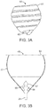
- FIG. 1A depicts a first embodiment of the invention, which is configured for insertion into a patient's organ, typically the stomach.
- Device 30 includes a proximal member 32 and a distal member 34, which are connected one to the other by a tether 36.
- the relative sizes of proximal member 32 and of distal member 24 are such that, after insertion into the stomach of a patient, the natural contractions of the stomach and, in general, the movements of the patient induce distal member 34 to enter the pyloric part of the gastro-intestinal tract and the duodenum, while proximal member 32 is retained in the stomach and cannot move beyond the pyloric valve because its diameter is larger than the pyloric valve opening.
- proximal member 32 includes a first occluding member 38, disposed in a central position within an apron member 40.
- First occluding member 38 may be formed from an elongated, narrower configuration as shown in FIG. 1A to a contracted, wider configuration as shown in FIG. 1B .
- first occluding member 38 has a helical design with a plurality of turns 42, which are configured to nest one adjacent to the other to assume the compact, bulbous shape illustrated in FIG. 1B .
- Apron member 40 wraps around first occluding member 38, providing proximal member 32 with a enlarged diameter and preventing the passage of proximal member 32 through the pyloric valve.
- apron member 40 includes an essentially cylindrical proximal portion 44 connected to an essentially conical distal portion 46 that extends from tether 36 to proximal portion 44.
- This configuration of apron member 40 is designed to provide an intermittent plugging effect on the pyloric valve and to avoid or anyways minimize abrasive contact with the wall of the pyloric valve during such plugging effect, so to prevent or minimize patient discomfort and irritations or even lacerations to the mucosa of the stomach and, in general, to the gastro-intestinal tract.
- Distal portion 46 may have a smaller wall thickness than proximal portion 44, both providing a gentler, suppler contact with the pyloric valve, and also facilitating the reversal of apron member 44 during insertion into a patient's stomach from a position substantially aligned with tether 36 to the position that wraps around first occluding member 38, as explained in greater detail below.
- apron member 40 may extend proximally for various lengths, surrounding first occluding member 38 partially or completely. Further, in different variants of the present embodiment, apron member 40 may be spaced from first occluding member 38 at various distances to create an interstice 48 of different amplitudes between first occluding member 38 and apron member 40.
- Second occluding member 34 may exhibit a variety of contours and in general, is shaped to facilitate its transition out of the stomach and into the duodenum, and to avoid or minimize abrasive contact with the walls of the stomach and of the pylorus.
- second occluding member 34 has a bulbous shape, essentially formed by two rounded, frusto-conical portions 50 connected at their wider bases.
- Device 30 may be manufactured from a variety of materials, for example, from a resilient plastic such as a silicone or urethane plastic, which may be reinforced in selected portions.
- the selected material should be biocompatible, resistant to the stomach environment, for example to stomach acids, and soft to the contact with the stomach and duodenal walls.
- the desired material should also provide device 30 with the desired shape while retaining sufficient flexibility for the insertion process in the stomach, for later reverting to the desired position within the gastro-intestinal tract, and for adapting to the various movements of the stomach and, in general, of the body of the patient.
- Inserts may be integrally included within the body of device 30 to increase certain mechanical properties in certain areas.
- an insert such as a metallic cylinder
- second occluding member 34 may be embedded within second occluding member 34 to increase weight and to facilitate retention by gravity within the pylorus.
- Another insert such as a fabric piece
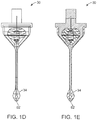
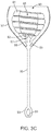
- FIG. 1C illustrates, among other things, one variant of the embodiment of FIGS. 1A and 1B , in which a stabilizing cap 54 is added to maintain first occluding member 38 in the contracted, wider configuration, and also to increase bulk and to prevent the introduction of food or other gastric products within interstice 48.
- device 30 is introduced in a patient's stomach in the elongated, narrower configuration of FIG. 1A , with apron member 40 oriented in the opposite direction to that shown in FIG. 1A , that is, to cover tether 36 while the free end of distal portion 46 is oriented proximally, in the direction of second occluding member 34.
- device 30 is disposed within a tube (not shown) and is caused to exit the tube with proximal end 52 first, followed by the rest of the device.
- device 30 When device 30 has partially exited the tube (or alternatively, the tube has been retracted from device 30) so to leave apron member 40 outside of the tube, device 30 is pulled inside the tube, but because apron member 40 surrounds and wraps around the end of the tube, such a pulling of device 30 inwards into the tube, causing apron member 40 to flip over and change orientation, so to wrap around first occluding member 38. After such a flipping around of apron member 40 has been achieved, device 30 is completely ejected from the tube and becomes disposed in the stomach. Alternatively, device 30 may be introduced in a patient's stomach with apron member 40 already oriented proximally, making unnecessary the previously described flipping operation.
- first occluding member 38 makes it recoil and assume the contracted configuration, similar to that shown in FIG. 1B
- the fully contracted, wider configuration of first occluding member 38 is achieved and maintained as follows.
- a connecting member 56 is coupled (for example, by a first string) to a release member 58.
- a second string 60 is looped around device 30, running outside and along device 30 starting from a first free end, and then extending within connecting member 56 through lumen 66, and then (within a lumen or a tube) within turns 42, successively entering a lumen 62 in tether 36 and second occluding member 34 (see also FIGS. 1D and IE), and eventually exiting device 30 with a second free end.
- first occluding member 38 is locked into its contracted, wider condition on a permanent basis.
- second string 60 is removed by pulling on one free end and by having second string 60 slide through the lumens within device 30, eventually exiting device 30 entirely.
- Device 30 is now free to move freely within the stomach, and the natural contractions of the stomach, in addition to any other movements of the patient's body, cause distal member 34 to move into the pylorus, while the size of proximal member 32 prevents it from moving into the pylorus and forces it to reside in the stomach.
- distal member 34 will eventually be disposed in the pylorus, and any inserts of a heavier weight will facilitate retention of distal member 34 in the pylorus, while proximal member 32 will act as an intermittent plug against the pyloric valve, because stomach contractions and other body movements will cause proximal member 32 to move towards and away from the pyloric valve, acting as an intermittent plug and allowing the passage of some food from time to time.
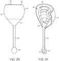
- device 31 may also include a distal member 33 connected or attached via tether 35 to proximal member 37.
- proximal member 37 may comprise an apron member 39 which defines a curved or otherwise arcuate surface which tapers radially from tether 35 at a distal portion 41 (which typically contacts the stomach interior surface when in use) to a curved proximal portion 43 which has a relatively larger diameter and which may define a circumferential lip or edge 53 which is atraumatic to surrounding tissue.
- Apron member 39 may define a channel or interstice 45 within which first occluding member 47 may reside when occluding member 47 is in its contracted deployment configuration, as illustrated.
- apron member 47 With occluding member 47 contracted, apron member 47 may be configured to entirely or at least partially encircle or enclose occluding member 47, as illustrated in FIGS. 2D and 2E which respectively show side and cross-sectional perspective views.
- interstice 47 may be left open when in use in the patient body or an additional cap member or covering may be optionally attached to fully enclose apron member 39 and occluding member 47 within, if so desired.
- Occluding member 47 may be formed into a coiled or wound structure having a plurality of turns and a distal end which is attached, coupled, or otherwise formed integrally with device 31 at connecting portion 49. Because of its coiled or wound helical structure, occluding member 47 may be extended in a low-profile configuration, as above, for delivery into the patient body and then allowed to compress or contract into its coiled structure which forms a diameter or cross-sectional area which is relatively larger than a diameter of distal member 33 to inhibit or prevent the passage of proximal member 37 through the pylorus when in use. As in the aforementioned embodiment, occluding member 47 may be biased or configured to self-contract.
- a string member or other locking mechanism may be actuated to compress and/or lock the structure such that the expanded configuration is maintained and prevented from releasing and reconfiguring back into its low-profile configuration.
- Distal member 33 may further define a lumen or channel 51 to facilitate the placement and/or positioning of device 31 within the patient body.
- portion 63 may be coupled to a complementary securement mechanism positioned within apron member 37.
- the securement mechanism may be comprised of a connecting portion 55 which extends distally within apron member 37.
- Connecting portion 55 may have a securement member 57, such as a tapered portion, and a stop member 59 which each limit the movement of portion 63 relative to connecting portion 55.
- occluding member 61 is shown in its collapsed and locked configuration while secured within interstice 45 and encircled by apron member 37.
- securement member 57 may be advanced at least partially within channel 65 formed by the wound occluding member 61 to prevent the relative movement or release of occluding member 61 from connecting portion 55.
- the connecting portion 55 is illustrated as an example and is not intended to be limiting. Other known securement mechanisms may be utilized as practicable.
- the device may be introduced into the patient body in a minimally invasive manner, e.g., per-orally and through the esophagus into the patient's stomach, the device may be delivered in its low-profile configuration, e.g., where the occluding member is in its uncoiled or unwound elongate configuration.
- the device may be delivered in a partially locked configuration.
- the device Once within the stomach, for instance, the device may be coiled or wound into its deployment configuration and the occluding member may be affirmatively locked into position relative to the device such that its enlarged profile inhibits or prevents the passage of the device through the pylorus.
- various mechanisms may be utilized to confirm its securement.
- One example includes having the string for locking the occluding member be color-coded such that one portion of the string is of a different color, e.g., red, than the remainder of the string.
- the string is tensioned to lock the occluding member, once the color-coded portion is exposed from the device the user may visually confirm that the occluding member is locked into its deployment configuration.
- the amount of tension required to lock the device may be calibrated to increase to a preset level once the device is locked such that the user may confirm by tactile feedback that the device is indeed locked.
- Other alternative mechanisms for locking confirmation or detection of the occluding device may additionally include sensors incorporated within the device.
- An example is illustrated in the cross-sectional side view of FIG. 1F , which shows sensor 67 positioned within the device.
- Sensor 67 may incorporate any number of detection modalities, e.g., acoustic, ultrasonic, electrical, electromagnetic, optical (for instance, detecting changes in color, wavelength, frequency, etc.), chemical, etc. which may sense changes in the occluding member from its coiled deployment configuration or changes in the string tension, connecting member 56, or release member 58.
- device 30 assists in the treatment of obesity by limiting the passage of food from the stomach into the intestine, and at the same time by reducing the intake of food by the patient due to the sense of fullness generated by the retention of food in the stomach for a longer time and also by to the presence of device 30 in the stomach.
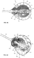
- FIGS. 4A and 4B show perspective views of a helical assembly 70 having a proximal member 72 reconfigured from its elongated configuration into its enlarged, coiled and nested configuration.
- the tether 74 may be seen extending from a compliant region 78 near a distal end of the proximal member 72 and a distal member 76 attached at a distal end of the tether 74.
- the compliant region 78 may be provided with a variable stiffness to be more benign to the contacted tissue and to further prevent trauma to the surrounding tissue.
- various coatings may be applied to the device, for example, for coefficient of friction, lubricity, enhanced biochemical durability, anti-microbial performance, etc.
- FIG. 4B shows a cross-sectional side view of the coiled and locked assembly 70 which in this variation illustrates the elongate coiled member 80 having a contoured profile 84.
- the profile 84 may define a projecting portion which may form a contact interface 82 when coiled into its nesting configuration with the adjacent coil although reversed contours may also be used to prevent the inward displacement of the nested loops.
- the contoured profile 84 may also enhance alignment of the structure during deployment as well.
- the edges of the coiled member 80 may also be radiused to reduce exposure of any edges to the gastric tissue.
- the coiled member 80 may form a compacted shape which may form an enclosed space 88 within and which may be configured into a spherically-shaped structure, as shown.
- a central column 86 may extend through the center of the proximal member 72 to lock the shape of the member 72.
- the central column 86 may be formed in part by a distal hub 90 which may be anchored or attached at a distal end of the proximal member 72 and also optionally attached to the hub where the tether 74 is attached to the proximal member 72.
- a proximal plug 94 may be seated 96 at a proximal end of the coiled member 80 and extend into an coupled attachment to the distal hub 90 which may be connected via, e.g., a collar 92 such as a directional C-clip, etc.
- a reinforcing member 98 such as a wire or suture length may be coupled to the distal hub 90 and extend through the tether 74 into attachment with the distal member 76.
- a distal weight 100 may also be optionally integrated in the distal member 76 as well. The inclusion of a reinforcing member 98 may prevent the over-extension of the tether 74 during deployment and use. The member 98 may also function to prevent the detachment of the tether 74 or distal member 76 in the unlikely event that the tether 74 fails.
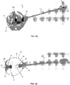
- FIGS. 5A and 5B show cross-sectional side and perspective views of the proximal member 72 to illustrate detail features for locking the proximal member 72 into its enlarged and compacted configuration.
- the proximal plug 94 may include a release mechanism 110 which extends through a proximal end of the plug 94 and is secured via one or more release securement members 112 within the plug 94.
- the release mechanism 110 may be toggled proximally and distally relative to the plug 94 to selectively lock or unlock one or more tensioning wires which extend transversely through the coiled member 80.
- the release mechanism 110 may be formed to have a rigid lip to facilitate its grasping by endoscopic tools when locking or unlocking the mechanism 110.
- the release mechanism 110 may also integrated a valve, such as a duck-billed valve, to prevent solid matter from entering the internal space of the proximal member 72.
- the collar 92 may also be seen coupling the distal hub 90 and the proximal plug 94 to one another. As the coiled member 80 configures into the enlarged configuration, the plug 94 may come into a mating engagement with the distal hub 90 which may then be joined by the collar 92 housed around the proximal plug 94.
- one or more tensioning wires may extend through the coiled member 80 in a transverse direction.
- the tensioning wires may be formed of various wires or other high-strength force fibers.
- the terminal end of the coiled member 80 may integrate one or more tensioning wire pins 114, 116, as shown in FIG. 5A , to which one or more corresponding collets 120, 122, 124 are attached and which also have corresponding lock lines 126, 128, 130 extending from their respective pins.
- the lock lines 126, 128, 130 may be located uniformly about the circumference of the proximal member and extend transversely through respective lumens defined through the coiled member 80, as shown in FIG. 5B . Although three lock lines are shown, this is done for illustrative purposes and any number of lock lines may be utilized at uniform (e.g., four lock lines positioned at 90 degrees relative to one another about a circumference of the proximal member 72) or arbitrary locations around the proximal member 72. Moreover, multiple lock lines may further provide for locking redundancy such that if one lock line were to fail, the proximal member 72 may still retain its enlarged structure.
- the lock lines may be engaged through the respective collets to allow for unidirectional passage of the lock lines.
- the lock lines may be pulled in only a tensioning direction to prevent or inhibit the unraveling of the proximal member 72.
- the collets or pins may be optionally radio-opaque to facilitate visualization of the device through, e.g., fluoroscopic visualization, to provide for confirmation of the locked status of the proximal member 72.
- FIGS. 6A and 6B show perspective and cross-sectional perspective views of a covered obstructing assembly 140.
- a covering 142 may enclose the coiled member 80 partially or completely such that the surface presented to the surrounding tissue remains completely smooth and uniform.
- the covering 142 may approximate the enlarged shape of the proximal member 72 such that the coiled member 80 may be formed entirely within the covering 142 itself, as described herein.
- a tissue interface 144 may be positioned by the terminal end of the coiled member 80 so as to present a smooth surface against the surrounding tissue.
- a strain relief hub section 146 may be incorporated between the covering 142 and tether 74 so as to prevent the excessive strain at the connection point due to the softened structure.
- the strain relief hub section 146 may be internally expandable such that it is rotationally secure. It may also be provided as a single-molded part that can be expanded by compression.
- An attachment collar 148 in an alternative variation, may extend into the receiving space 152 defined within the covering 142 and the proximal plug 94 may be detached from the distal hub 90 such that the central column is discontinuous.
- the attachment collar 148 may be configured to receive the pins at the terminal ends of the lock lines to lock the proximal member 72 in its configuration and may also join the member 72 to the covering 142. Having a decoupled column may provide for additional flexibility to the proximal member 72 which may conform or flex to a greater extent.
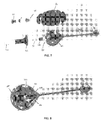
- FIG. 7 shows a perspective assembly view of the various components which may form the covered embodiment.
- the covering 142 may incorporate the distal hub 90 and attachment collar 148 within the receiving space 152, as shown in the partial cross-section perspective view of FIG. 8 .
- the coiled member 80 may be introduced into the receiving space 152 through opening 150 as a component separate from the covering 142.
- the proximal plug 94 and release mechanism 110 may also be integrated with the coiled member 80.
- a delivery tube 160 having a tapered covering interface 162 may be provided for attachment to the opening 150.
- the delivery tube 160 may provide an access passage for the introduction of the coiled member 80 in its elongate form into the covering 142.
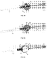
- FIGS. 9A to 9C illustrate partial cross-sectional perspective views of an example showing how the coiled member 80 may be deployed.
- the covering 142 With the covering 142 attached temporarily to the covering interface 162 at opening 150, as shown in FIG. 9A , the covering 142 may be positioned within the stomach.
- FIG. 9B illustrates how the covering 142 may be devoid of the coiled member 80.
- the coiled member 80 may then be introduced through the delivery tube 160 and into the receiving space 152 where it may then coil into its nested and compacted configuration.
- the covering interface 162 may be pulled from the opening 150 to detach itself and the tissue interface 144 and release mechanism 110 may obstruct or plug the covering opening 150.
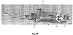
- a delivery assembly 170 In delivering and deploying the obstructing device into the stomach, one variation of a delivery assembly 170 is shown in the perspective view of FIG. 10 .
- the assembly 170 may generally having a tensioning control assembly 172 attached to a delivery tube 184 extending from the control assembly 172.
- the coiled member 80 may be loaded within the delivery tube 184 in its elongated configuration with the tether 74 and distal member 76 positioned within the delivery tube 184 distal to the coiled member 80.
- the lock lines may pass from the elongate member 80 within the delivery tube 184 and extend proximally through the delivery tube 184 and into the control assembly 172.
- Each of the lock lines may be routed to a corresponding tensioning spring 174 which may provide a continual or intermittent tensioning force of variable magnitude upon the lock lines which may help to prevent the lock lines from tangling and which may also facilitate the tensioning of the lock lines when reconfiguring the coiled member 80 into its compacted shape.
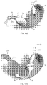
- the obstructing device 70 When deployed, the obstructing device 70 may be placed within the stomach ST of a patient, as shown in the partial cross-sectional view of FIG. 11A .
- the esophagus ES, pylorus PY, and duodenum DU are also illustrated for reference.
- the proximal member 72 With the proximal member 72 in its enlarged and nested configuration, the device 70 may lie within the stomach ST.
- the stomach ST may begin to contract such that the distal member 76 is moved through the stomach ST towards the pylorus PY. Because the distal member 76 is sized for passage through the pylorus PY, the distal member 76 may pass through to become positioned within the duodenum DU of the patient.
- the proximal member 72 may remain within the stomach ST and cover the pylorus PY, as shown in FIG. 11B .
- the proximal member 72 may begin to intermittently obstruct and expose the pylorus PY allowing food and/or liquid to pass from the stomach at a slowed rate thus forcing the patient to feel full for longer periods of time.
- the device 70 may be allowed to then reposition itself within the stomach ST.
- the device 70 may be collapsed within the stomach ST and removed back through the esophagus ES in its elongate configuration.
- FIG. 12A illustrates how an optional access tube 190 may be positioned through the esophagus ES and an endoscope 192 or other instrument having, e.g., a grasper 194, may be passed through the access tube 190 and into proximity to the proximal member 72.
- the grasper 194 may be brought into contact with the release mechanism 110, as shown in the perspective view of FIG. 12B , which may then be pulled to unlock the proximal member 72.
- the entire central column 86 may be removed from the proximal member 72, as shown in FIG. 12C , and removed from the stomach ST. With the proximal member 72 released, the coiled member 80 may be pulled through the access tube 190 and through the esophagus ES in its collapsed and elongate profile, as shown in FIG. 12D .
Landscapes
- Health & Medical Sciences (AREA)
- Child & Adolescent Psychology (AREA)
- Obesity (AREA)
- Nursing (AREA)
- Orthopedic Medicine & Surgery (AREA)
- Engineering & Computer Science (AREA)
- Biomedical Technology (AREA)
- Heart & Thoracic Surgery (AREA)
- Vascular Medicine (AREA)
- Life Sciences & Earth Sciences (AREA)
- Animal Behavior & Ethology (AREA)
- General Health & Medical Sciences (AREA)
- Public Health (AREA)
- Veterinary Medicine (AREA)
- Surgical Instruments (AREA)
- Prostheses (AREA)
Applications Claiming Priority (3)
| Application Number | Priority Date | Filing Date | Title |
|---|---|---|---|
| US201361791433P | 2013-03-15 | 2013-03-15 | |
| EP14767867.6A EP2967382B1 (de) | 2013-03-15 | 2014-03-12 | Vorrichtung zur magenobstruktion |
| PCT/US2014/024475 WO2014150894A1 (en) | 2013-03-15 | 2014-03-12 | Locking gastric obstruction device and method of use |
Related Parent Applications (2)
| Application Number | Title | Priority Date | Filing Date |
|---|---|---|---|
| EP14767867.6A Division-Into EP2967382B1 (de) | 2013-03-15 | 2014-03-12 | Vorrichtung zur magenobstruktion |
| EP14767867.6A Division EP2967382B1 (de) | 2013-03-15 | 2014-03-12 | Vorrichtung zur magenobstruktion |
Publications (1)
| Publication Number | Publication Date |
|---|---|
| EP3351218A1 true EP3351218A1 (de) | 2018-07-25 |
Family
ID=51580851
Family Applications (2)
| Application Number | Title | Priority Date | Filing Date |
|---|---|---|---|
| EP17201397.1A Withdrawn EP3351218A1 (de) | 2013-03-15 | 2014-03-12 | Verriegelungsvorrichtung für magenobstruktion |
| EP14767867.6A Not-in-force EP2967382B1 (de) | 2013-03-15 | 2014-03-12 | Vorrichtung zur magenobstruktion |
Family Applications After (1)
| Application Number | Title | Priority Date | Filing Date |
|---|---|---|---|
| EP14767867.6A Not-in-force EP2967382B1 (de) | 2013-03-15 | 2014-03-12 | Vorrichtung zur magenobstruktion |
Country Status (8)
| Country | Link |
|---|---|
| US (3) | US10070981B2 (de) |
| EP (2) | EP3351218A1 (de) |
| JP (1) | JP6283972B2 (de) |
| AU (1) | AU2014235521B2 (de) |
| BR (1) | BR112015023344B1 (de) |
| CA (1) | CA2905787C (de) |
| ES (1) | ES2675373T3 (de) |
| WO (1) | WO2014150894A1 (de) |
Cited By (1)
| Publication number | Priority date | Publication date | Assignee | Title |
|---|---|---|---|---|
| US10874538B2 (en) | 2013-03-15 | 2020-12-29 | Baronova, Inc. | Locking gastric obstruction device and method of use |
Families Citing this family (3)
| Publication number | Priority date | Publication date | Assignee | Title |
|---|---|---|---|---|
| WO2018136967A1 (en) * | 2017-01-23 | 2018-07-26 | Baronova, Inc. | Gastric obstruction device deployment assembly and methods of delivering and deploying a gastric obstruction device |
| US12465364B2 (en) | 2020-08-27 | 2025-11-11 | Boston Scientific Scimed, Inc. | Devices, systems, and methods for pyloric occlusion |
| KR102930656B1 (ko) * | 2021-04-28 | 2026-02-24 | 보스톤 싸이엔티픽 싸이메드 인코포레이티드 | 십이지장 차단 및 위 용량 감소를 위한 디바이스 및 시스템 |
Citations (17)
| Publication number | Priority date | Publication date | Assignee | Title |
|---|---|---|---|---|
| US5509888A (en) | 1994-07-26 | 1996-04-23 | Conceptek Corporation | Controller valve device and method |
| US6067991A (en) | 1998-08-13 | 2000-05-30 | Forsell; Peter | Mechanical food intake restriction device |
| US6527701B1 (en) | 2000-09-29 | 2003-03-04 | Precision Medical Devices, Inc. | Body fluid flow control device |
| US20040172142A1 (en) | 2001-08-27 | 2004-09-02 | Stack Richard S. | Satiation devices and methods |
| US20050273060A1 (en) | 2004-06-03 | 2005-12-08 | Mayo Foundation For Medical Education And Research | Obesity treatment and device |
| US7011621B2 (en) | 2000-09-29 | 2006-03-14 | Precision Medical Devices, Inc. | Body fluid flow control method and device |
| US7037344B2 (en) | 2002-11-01 | 2006-05-02 | Valentx, Inc. | Apparatus and methods for treatment of morbid obesity |
| US7120498B2 (en) | 2001-05-01 | 2006-10-10 | Intrapace, Inc. | Method and device for securing a functional device to a stomach |
| US7122058B2 (en) | 2002-12-02 | 2006-10-17 | Gi Dynamics, Inc. | Anti-obesity devices |
| US20070016262A1 (en) | 2005-07-13 | 2007-01-18 | Betastim, Ltd. | Gi and pancreatic device for treating obesity and diabetes |
| US7167750B2 (en) | 2003-02-03 | 2007-01-23 | Enteromedics, Inc. | Obesity treatment with electrically induced vagal down regulation |
| US20070083224A1 (en) | 2005-06-16 | 2007-04-12 | Hively Robert L | Gastric bariatric apparatus with selective inflation and safety features |
| WO2007092390A2 (en) * | 2006-02-03 | 2007-08-16 | Baronova, Inc. | Devices and methods for gastrointestinal stimulation |
| US20090182358A1 (en) | 2007-09-07 | 2009-07-16 | Baronova.Inc. | Device for intermittently obstructing a gastric opening and method of use |
| US20100114150A1 (en) * | 2007-02-07 | 2010-05-06 | Duocure, Inc. | Duodenal stimulation devices and methods for the treatment of conditions relating to eating disorders |
| WO2012011105A2 (en) * | 2010-07-22 | 2012-01-26 | Pierre Sharvit | Pancreatiobiliary diversion device |
| US20130006381A1 (en) * | 2008-04-09 | 2013-01-03 | E2 Llc | Pyloric valve devices and methods |
Family Cites Families (133)
| Publication number | Priority date | Publication date | Assignee | Title |
|---|---|---|---|---|
| US2499045A (en) | 1948-08-16 | 1950-02-28 | Walker Frank Ray | Rectal dilator and medicator |
| US3154077A (en) | 1962-06-04 | 1964-10-27 | Joseph P Cannon | Hemostatic device for anal surgery |
| US3915171A (en) | 1974-06-06 | 1975-10-28 | Dennis William Shermeta | Gastrostomy tube |
| US4133315A (en) | 1976-12-27 | 1979-01-09 | Berman Edward J | Method and apparatus for reducing obesity |
| US4315509A (en) | 1977-01-10 | 1982-02-16 | Smit Julie A | Insertion and removal catheters and intestinal tubes for restricting absorption |
| US4246893A (en) | 1978-07-05 | 1981-01-27 | Daniel Berson | Inflatable gastric device for treating obesity |
| US4368739A (en) | 1979-07-18 | 1983-01-18 | Nelson Jr Richard L | Long intestinal catheter |
| US4240412A (en) | 1979-08-29 | 1980-12-23 | Eugene James | Medical device |
| US4416267A (en) | 1981-12-10 | 1983-11-22 | Garren Lloyd R | Method and apparatus for treating obesity |
| US4485805A (en) | 1982-08-24 | 1984-12-04 | Gunther Pacific Limited Of Hong Kong | Weight loss device and method |
| WO1988000027A1 (en) | 1986-07-09 | 1988-01-14 | Angelchik Jean P | Method for treatment of morbid obesity |
| US4517979A (en) | 1983-07-14 | 1985-05-21 | Cordis Corporation | Detachable balloon catheter |
| US5067957A (en) | 1983-10-14 | 1991-11-26 | Raychem Corporation | Method of inserting medical devices incorporating SIM alloy elements |
| US4648383A (en) | 1985-01-11 | 1987-03-10 | Angelchik Jean P | Peroral apparatus for morbid obesity treatment |
| US4598699A (en) | 1985-06-10 | 1986-07-08 | Garren Lloyd R | Endoscopic instrument for removing stomach insert |
| US4657020A (en) | 1985-07-10 | 1987-04-14 | Jayco Pharmaceuticals | Method of using a foreign object protector hood |
| US4694827A (en) | 1986-01-14 | 1987-09-22 | Weiner Brian C | Inflatable gastric device for treating obesity and method of using the same |
| GB8603099D0 (en) | 1986-02-07 | 1986-03-12 | Blass K G | Gastrointestinal module |
| US4735214A (en) | 1986-09-05 | 1988-04-05 | Berman Irwin R | Gastrointestinal diagnostic capsule and method of use |
| US5527336A (en) | 1986-12-09 | 1996-06-18 | Boston Scientific Corporation | Flow obstruction treatment method |
| US4762128A (en) | 1986-12-09 | 1988-08-09 | Advanced Surgical Intervention, Inc. | Method and apparatus for treating hypertrophy of the prostate gland |
| US4836204A (en) | 1987-07-06 | 1989-06-06 | Landymore Roderick W | Method for effecting closure of a perforation in the septum of the heart |
| DE3737753A1 (de) | 1987-11-06 | 1989-06-15 | Pfersee Chem Fab | Waessriges ausruestungsmittel und verfahren zur weichen hydrophob/oleophob-behandlung von fasermaterialien |
| JP2691937B2 (ja) | 1988-07-05 | 1997-12-17 | カンテニース,ジョゼ | 胃内バルーン |
| US4925446A (en) | 1988-07-06 | 1990-05-15 | Transpharm Group Inc. | Removable inflatable intragastrointestinal device for delivering beneficial agents |
| US4930496A (en) | 1988-07-22 | 1990-06-05 | Vance Products, Inc. | Method and device for removing a stone from a ureter using extracorporeal shock wave lithotripsy |
| US5514091A (en) | 1988-07-22 | 1996-05-07 | Yoon; Inbae | Expandable multifunctional manipulating instruments for various medical procedures |
| US4946440A (en) | 1988-10-05 | 1990-08-07 | Hall John E | Evertible membrane catheter and method of use |
| US5011488A (en) | 1988-12-07 | 1991-04-30 | Robert Ginsburg | Thrombus extraction system |
| FR2641692A1 (fr) | 1989-01-17 | 1990-07-20 | Nippon Zeon Co | Bouchon de fermeture d'une breche pour application medicale et dispositif pour bouchon de fermeture l'utilisant |
| SE465017B (sv) | 1989-11-24 | 1991-07-15 | Lars Knutson | Anordning foer segmentell perfusion/aspiration av grovtarmen |
| US5674192A (en) | 1990-12-28 | 1997-10-07 | Boston Scientific Corporation | Drug delivery |
| US5331975A (en) | 1990-03-02 | 1994-07-26 | Bonutti Peter M | Fluid operated retractors |
| IL94138A (en) | 1990-04-19 | 1997-03-18 | Instent Inc | Device for the treatment of constricted fluid conducting ducts |
| DE4012642A1 (de) | 1990-04-20 | 1991-10-24 | Wolf Gmbh Richard | Vorrichtung mit ballonen fuer krankheitsbehandlungen |
| US5108420A (en) | 1991-02-01 | 1992-04-28 | Temple University | Aperture occlusion device |
| US5234454A (en) | 1991-08-05 | 1993-08-10 | Akron City Hospital | Percutaneous intragastric balloon catheter and method for controlling body weight therewith |
| US5282829A (en) | 1991-08-15 | 1994-02-01 | United States Surgical Corporation | Hollow body implants |
| IT1260485B (it) | 1992-05-29 | 1996-04-09 | Procedimento e dispositivo per il trattamento dell'obesita' di un paziente | |
| US5306300A (en) | 1992-09-22 | 1994-04-26 | Berry H Lee | Tubular digestive screen |
| FR2706764B1 (de) | 1993-06-24 | 1995-08-04 | Synthelabo | |
| US5540701A (en) | 1994-05-20 | 1996-07-30 | Hugh Sharkey | Passive fixation anastomosis method and device |
| US5545210A (en) | 1994-09-22 | 1996-08-13 | Advanced Coronary Technology, Inc. | Method of implanting a permanent shape memory alloy stent |
| US5634936A (en) | 1995-02-06 | 1997-06-03 | Scimed Life Systems, Inc. | Device for closing a septal defect |
| US5676688A (en) | 1995-02-06 | 1997-10-14 | Rtc, Inc. | Variably inflatable medical device |
| US5750585A (en) | 1995-04-04 | 1998-05-12 | Purdue Research Foundation | Super absorbent hydrogel foams |
| US5601581A (en) | 1995-05-19 | 1997-02-11 | General Surgical Innovations, Inc. | Methods and devices for blood vessel harvesting |
| US6071300A (en) | 1995-09-15 | 2000-06-06 | Sub-Q Inc. | Apparatus and method for percutaneous sealing of blood vessel punctures |
| US5707355A (en) | 1995-11-15 | 1998-01-13 | Zimmon Science Corporation | Apparatus and method for the treatment of esophageal varices and mucosal neoplasms |
| US6162201A (en) | 1995-12-01 | 2000-12-19 | Cohen; Kenneth L. | Internal urinary catheter |
| US5853422A (en) | 1996-03-22 | 1998-12-29 | Scimed Life Systems, Inc. | Apparatus and method for closing a septal defect |
| US6702846B2 (en) | 1996-04-09 | 2004-03-09 | Endocare, Inc. | Urological stent therapy system and method |
| US5782916A (en) | 1996-08-13 | 1998-07-21 | Galt Laboratories, Inc. | Device for maintaining urinary continence |
| WO1998010729A1 (en) | 1996-09-16 | 1998-03-19 | Exogen, Inc. | Cast punch |
| US5947991A (en) | 1997-01-07 | 1999-09-07 | Cowan; Robert K. | Single balloon device for cervix |
| US6159219A (en) | 1997-05-16 | 2000-12-12 | Scimed Life Systems, Inc | Stent retrieval device |
| US5820584A (en) | 1997-08-28 | 1998-10-13 | Crabb; Jerry A. | Duodenal insert and method of use |
| FR2769491B1 (fr) | 1997-10-15 | 2000-01-07 | Patrick Sangouard | Sphincter artificiel reglable a commande magnetique |
| CA2307764A1 (en) | 1997-11-07 | 1999-05-20 | Salviac Limited | Implantable occluder devices for medical use |
| US6254642B1 (en) | 1997-12-09 | 2001-07-03 | Thomas V. Taylor | Perorally insertable gastroesophageal anti-reflux valve prosthesis and tool for implantation thereof |
| US5976174A (en) | 1997-12-15 | 1999-11-02 | Ruiz; Carlos E. | Medical hole closure device and methods of use |
| US6152144A (en) | 1998-11-06 | 2000-11-28 | Appriva Medical, Inc. | Method and device for left atrial appendage occlusion |
| US6427089B1 (en) | 1999-02-19 | 2002-07-30 | Edward W. Knowlton | Stomach treatment apparatus and method |
| USRE44297E1 (en) | 1999-06-18 | 2013-06-11 | Radi Medical Systems Ab | Tool, a sealing device, a system and a method for closing a wound |
| US6112703A (en) | 1999-06-22 | 2000-09-05 | Jw Pet Company, Inc. | Shrouded chewable pet toys and method of making |
| US20050192629A1 (en) | 1999-06-25 | 2005-09-01 | Usgi Medical Inc. | Methods and apparatus for creating and regulating a gastric stoma |
| US7160312B2 (en) | 1999-06-25 | 2007-01-09 | Usgi Medical, Inc. | Implantable artificial partition and methods of use |
| US6994092B2 (en) | 1999-11-08 | 2006-02-07 | Ev3 Sunnyvale, Inc. | Device for containing embolic material in the LAA having a plurality of tissue retention structures |
| US6458153B1 (en) | 1999-12-31 | 2002-10-01 | Abps Venture One, Ltd. | Endoluminal cardiac and venous valve prostheses and methods of manufacture and delivery thereof |
| US6790218B2 (en) | 1999-12-23 | 2004-09-14 | Swaminathan Jayaraman | Occlusive coil manufacture and delivery |
| US6600953B2 (en) | 2000-12-11 | 2003-07-29 | Impulse Dynamics N.V. | Acute and chronic electrical signal therapy for obesity |
| AU2001233098A1 (en) | 2000-01-27 | 2001-08-07 | Sterilis, Inc. | Cavity enlarger method and apparatus |
| MXPA00001922A (es) | 2000-02-24 | 2002-03-08 | De Hayos Garza Andres | Cateter de balon intragastrico percutaneo para tratamiento de la obesidad. |
| US6503264B1 (en) | 2000-03-03 | 2003-01-07 | Bioenterics Corporation | Endoscopic device for removing an intragastric balloon |
| KR100583021B1 (ko) | 2000-06-14 | 2006-05-23 | 퓨아 그린 가부시키가이샤 | 유성 화장료 및 그의 제조방법 |
| US6540789B1 (en) | 2000-06-15 | 2003-04-01 | Scimed Life Systems, Inc. | Method for treating morbid obesity |
| US6488962B1 (en) | 2000-06-20 | 2002-12-03 | Depomed, Inc. | Tablet shapes to enhance gastric retention of swellable controlled-release oral dosage forms |
| WO2002011696A2 (en) | 2000-08-08 | 2002-02-14 | Ev & M | Active tissue augmentation materials and method |
| US7651696B2 (en) | 2000-08-25 | 2010-01-26 | Nexeon Medical Systems, Inc. | Implantable device for treating disease states and methods of using same |
| JP2002102260A (ja) | 2000-09-28 | 2002-04-09 | Nipro Corp | 動脈内のシャントチューブ及びその使用方法 |
| US6579301B1 (en) | 2000-11-17 | 2003-06-17 | Syntheon, Llc | Intragastric balloon device adapted to be repeatedly varied in volume without external assistance |
| US6527739B1 (en) | 2000-12-29 | 2003-03-04 | Advanced Cardiovascular Systems, Inc. | Spiraled balloon arrangement for treatment of a tortuous vessel |
| US6572627B2 (en) | 2001-01-08 | 2003-06-03 | Shlomo Gabbay | System to inhibit and/or control expansion of anatomical features |
| CA2447377C (en) | 2001-05-17 | 2008-11-25 | Kiyoshi Hashiba | Intragastric device for treating obesity |
| US6558400B2 (en) | 2001-05-30 | 2003-05-06 | Satiety, Inc. | Obesity treatment tools and methods |
| US20020188354A1 (en) | 2001-06-12 | 2002-12-12 | Peghini Paolo Lino | Device to treat obesity by obstructing gastric outlet |
| US7160258B2 (en) | 2001-06-26 | 2007-01-09 | Entrack, Inc. | Capsule and method for treating or diagnosing the intestinal tract |
| US6951536B2 (en) | 2001-07-30 | 2005-10-04 | Olympus Corporation | Capsule-type medical device and medical system |
| US20040117031A1 (en) | 2001-08-27 | 2004-06-17 | Stack Richard S. | Satiation devices and methods |
| US6845776B2 (en) | 2001-08-27 | 2005-01-25 | Richard S. Stack | Satiation devices and methods |
| US20060052821A1 (en) | 2001-09-06 | 2006-03-09 | Ovalis, Inc. | Systems and methods for treating septal defects |
| US6755869B2 (en) | 2001-11-09 | 2004-06-29 | Boston Scientific Corporation | Intragastric prosthesis for the treatment of morbid obesity |
| US6740121B2 (en) | 2001-11-09 | 2004-05-25 | Boston Scientific Corporation | Intragastric stent for duodenum bypass |
| US20030120328A1 (en) | 2001-12-21 | 2003-06-26 | Transneuronix, Inc. | Medical implant device for electrostimulation using discrete micro-electrodes |
| US20030144708A1 (en) | 2002-01-29 | 2003-07-31 | Starkebaum Warren L. | Methods and apparatus for retarding stomach emptying for treatment of eating disorders |
| US7146984B2 (en) | 2002-04-08 | 2006-12-12 | Synecor, Llc | Method and apparatus for modifying the exit orifice of a satiation pouch |
| US7485141B2 (en) | 2002-05-10 | 2009-02-03 | Cordis Corporation | Method of placing a tubular membrane on a structural frame |
| US6790214B2 (en) | 2002-05-17 | 2004-09-14 | Esophyx, Inc. | Transoral endoscopic gastroesophageal flap valve restoration device, assembly, system and method |
| DK1549379T3 (da) | 2002-09-18 | 2014-01-20 | Asap Breathe Assist Pty Ltd | Næsehuledilateringsindretning |
| US8070743B2 (en) | 2002-11-01 | 2011-12-06 | Valentx, Inc. | Devices and methods for attaching an endolumenal gastrointestinal implant |
| US7025791B2 (en) | 2002-12-02 | 2006-04-11 | Gi Dynamics, Inc. | Bariatric sleeve |
| US7087072B2 (en) | 2003-01-22 | 2006-08-08 | Cardia, Inc. | Articulated center post |
| US7186251B2 (en) | 2003-03-27 | 2007-03-06 | Cierra, Inc. | Energy based devices and methods for treatment of patent foramen ovale |
| US7611480B2 (en) | 2003-04-24 | 2009-11-03 | Levy Mark M | Gastrointestinal bioreactor |
| BR0302240B8 (pt) | 2003-06-24 | 2013-02-19 | balço semi-estacionÁrio no antro gÁstrico com haste de ancoragem para induÇço de emagrecimento em seres humanos. | |
| US8821521B2 (en) | 2003-07-28 | 2014-09-02 | Baronova, Inc. | Gastro-intestinal device and method for treating addiction |
| US9498366B2 (en) | 2003-07-28 | 2016-11-22 | Baronova, Inc. | Devices and methods for pyloric anchoring |
| US20090259236A2 (en) | 2003-07-28 | 2009-10-15 | Baronova, Inc. | Gastric retaining devices and methods |
| US6994095B2 (en) | 2003-07-28 | 2006-02-07 | Medventure Associates Iv | Pyloric valve corking device and method |
| US9700450B2 (en) | 2003-07-28 | 2017-07-11 | Baronova, Inc. | Devices and methods for gastrointestinal stimulation |
| US8048169B2 (en) * | 2003-07-28 | 2011-11-01 | Baronova, Inc. | Pyloric valve obstructing devices and methods |
| US7735493B2 (en) | 2003-08-15 | 2010-06-15 | Atritech, Inc. | System and method for delivering a left atrial appendage containment device |
| JP3999176B2 (ja) | 2003-08-20 | 2007-10-31 | ジーイー・メディカル・システムズ・グローバル・テクノロジー・カンパニー・エルエルシー | X線ct装置、情報処理方法ならびに記憶媒体、プログラム |
| US20050247320A1 (en) | 2003-10-10 | 2005-11-10 | Stack Richard S | Devices and methods for retaining a gastro-esophageal implant |
| US20050192627A1 (en) | 2003-10-10 | 2005-09-01 | Whisenant Brian K. | Patent foramen ovale closure devices, delivery apparatus and related methods and systems |
| US7054690B2 (en) | 2003-10-22 | 2006-05-30 | Intrapace, Inc. | Gastrointestinal stimulation device |
| US20050149142A1 (en) | 2004-01-07 | 2005-07-07 | Starkebaum Warren L. | Gastric stimulation responsive to sensing feedback |
| US8147561B2 (en) | 2004-02-26 | 2012-04-03 | Endosphere, Inc. | Methods and devices to curb appetite and/or reduce food intake |
| US20050245788A1 (en) | 2004-04-28 | 2005-11-03 | Medtronic, Inc. | Esophageal delivery system and method with position indexing |
| US7842053B2 (en) | 2004-05-06 | 2010-11-30 | Nmt Medical, Inc. | Double coil occluder |
| US7704268B2 (en) | 2004-05-07 | 2010-04-27 | Nmt Medical, Inc. | Closure device with hinges |
| US8257389B2 (en) | 2004-05-07 | 2012-09-04 | W.L. Gore & Associates, Inc. | Catching mechanisms for tubular septal occluder |
| JP2008531071A (ja) * | 2005-01-05 | 2008-08-14 | シーガル ティゾニー | 略直線状の導管を介して物体内へ導入されて所定の曲線状構造を形成する装置及びこの装置の使用方法 |
| US20060259074A1 (en) | 2005-02-22 | 2006-11-16 | Brian Kelleher | Methods and devices for anchoring to soft tissue |
| EP1893142B1 (de) | 2005-05-09 | 2013-04-24 | Cook Medical Technologies LLC | Magensonde zur behandlung von adipositas |
| WO2006135857A2 (en) | 2005-06-10 | 2006-12-21 | Novalert, Inc. | Method and apparatus for monitoring implants |
| US20070056591A1 (en) | 2005-09-15 | 2007-03-15 | Mcswain Hugh | Fallopian tube occlusion devices and methods |
| US20090177288A1 (en) | 2005-10-29 | 2009-07-09 | Pnn Medical S.A. | Stent for Use in a Tubular Organ of a Body |
| EP1959865B1 (de) | 2005-12-15 | 2014-12-10 | The Cleveland Clinic Foundation | Gerät zur behandlung von klappen-regurgitation |
| WO2007075978A2 (en) | 2005-12-22 | 2007-07-05 | Wilson-Cook Medical Inc. | Coiled intragastric member for treating obesity |
| CA2656147A1 (en) | 2006-06-29 | 2008-01-03 | Slimedics Ltd. | Gastrointestinal prostheses |
| JP2009019587A (ja) | 2007-07-12 | 2009-01-29 | Toyota Motor Corp | 車両の制御装置 |
| EP3351218A1 (de) | 2013-03-15 | 2018-07-25 | Baronova, Inc. | Verriegelungsvorrichtung für magenobstruktion |
-
2014
- 2014-03-12 EP EP17201397.1A patent/EP3351218A1/de not_active Withdrawn
- 2014-03-12 EP EP14767867.6A patent/EP2967382B1/de not_active Not-in-force
- 2014-03-12 AU AU2014235521A patent/AU2014235521B2/en not_active Ceased
- 2014-03-12 CA CA2905787A patent/CA2905787C/en active Active
- 2014-03-12 WO PCT/US2014/024475 patent/WO2014150894A1/en not_active Ceased
- 2014-03-12 BR BR112015023344-9A patent/BR112015023344B1/pt not_active IP Right Cessation
- 2014-03-12 ES ES14767867.6T patent/ES2675373T3/es active Active
- 2014-03-12 JP JP2016501548A patent/JP6283972B2/ja not_active Expired - Fee Related
-
2015
- 2015-09-09 US US14/849,450 patent/US10070981B2/en active Active
-
2018
- 2018-08-10 US US16/101,034 patent/US10874538B2/en not_active Expired - Fee Related
-
2020
- 2020-11-24 US US17/103,537 patent/US20210077286A1/en not_active Abandoned
Patent Citations (21)
| Publication number | Priority date | Publication date | Assignee | Title |
|---|---|---|---|---|
| US5509888A (en) | 1994-07-26 | 1996-04-23 | Conceptek Corporation | Controller valve device and method |
| US6067991A (en) | 1998-08-13 | 2000-05-30 | Forsell; Peter | Mechanical food intake restriction device |
| US7011621B2 (en) | 2000-09-29 | 2006-03-14 | Precision Medical Devices, Inc. | Body fluid flow control method and device |
| US6689046B2 (en) | 2000-09-29 | 2004-02-10 | Precision Medical Devices, Inc. | Body fluid flow control method and device |
| US6527701B1 (en) | 2000-09-29 | 2003-03-04 | Precision Medical Devices, Inc. | Body fluid flow control device |
| US7120498B2 (en) | 2001-05-01 | 2006-10-10 | Intrapace, Inc. | Method and device for securing a functional device to a stomach |
| US20040172142A1 (en) | 2001-08-27 | 2004-09-02 | Stack Richard S. | Satiation devices and methods |
| US7037344B2 (en) | 2002-11-01 | 2006-05-02 | Valentx, Inc. | Apparatus and methods for treatment of morbid obesity |
| US7122058B2 (en) | 2002-12-02 | 2006-10-17 | Gi Dynamics, Inc. | Anti-obesity devices |
| US20070027548A1 (en) | 2002-12-02 | 2007-02-01 | Levine Andy H | Anti-obesity devices |
| US7167750B2 (en) | 2003-02-03 | 2007-01-23 | Enteromedics, Inc. | Obesity treatment with electrically induced vagal down regulation |
| US20050273060A1 (en) | 2004-06-03 | 2005-12-08 | Mayo Foundation For Medical Education And Research | Obesity treatment and device |
| US20070083224A1 (en) | 2005-06-16 | 2007-04-12 | Hively Robert L | Gastric bariatric apparatus with selective inflation and safety features |
| US20070016262A1 (en) | 2005-07-13 | 2007-01-18 | Betastim, Ltd. | Gi and pancreatic device for treating obesity and diabetes |
| WO2007092390A2 (en) * | 2006-02-03 | 2007-08-16 | Baronova, Inc. | Devices and methods for gastrointestinal stimulation |
| US20100114150A1 (en) * | 2007-02-07 | 2010-05-06 | Duocure, Inc. | Duodenal stimulation devices and methods for the treatment of conditions relating to eating disorders |
| US20090182358A1 (en) | 2007-09-07 | 2009-07-16 | Baronova.Inc. | Device for intermittently obstructing a gastric opening and method of use |
| US20090182357A1 (en) | 2007-09-07 | 2009-07-16 | Baronova, Inc. | Device for intermittently obstructing a gastric opening and method of use |
| US20090198210A1 (en) | 2007-09-07 | 2009-08-06 | Baronova, Inc. | Device for intermittently obstructing a gastric opening and method of use |
| US20130006381A1 (en) * | 2008-04-09 | 2013-01-03 | E2 Llc | Pyloric valve devices and methods |
| WO2012011105A2 (en) * | 2010-07-22 | 2012-01-26 | Pierre Sharvit | Pancreatiobiliary diversion device |
Cited By (1)
| Publication number | Priority date | Publication date | Assignee | Title |
|---|---|---|---|---|
| US10874538B2 (en) | 2013-03-15 | 2020-12-29 | Baronova, Inc. | Locking gastric obstruction device and method of use |
Also Published As
| Publication number | Publication date |
|---|---|
| BR112015023344B1 (pt) | 2022-05-31 |
| BR112015023344A2 (pt) | 2017-07-18 |
| US20160206461A1 (en) | 2016-07-21 |
| EP2967382A1 (de) | 2016-01-20 |
| JP2016512089A (ja) | 2016-04-25 |
| CA2905787A1 (en) | 2014-09-25 |
| AU2014235521A1 (en) | 2015-10-15 |
| WO2014150894A1 (en) | 2014-09-25 |
| EP2967382B1 (de) | 2018-05-09 |
| CA2905787C (en) | 2019-06-18 |
| US10874538B2 (en) | 2020-12-29 |
| US20180344500A1 (en) | 2018-12-06 |
| AU2014235521B2 (en) | 2018-01-04 |
| ES2675373T3 (es) | 2018-07-10 |
| JP6283972B2 (ja) | 2018-02-28 |
| US10070981B2 (en) | 2018-09-11 |
| HK1219216A1 (en) | 2017-03-31 |
| EP2967382A4 (de) | 2016-11-02 |
| US20210077286A1 (en) | 2021-03-18 |
Similar Documents
| Publication | Publication Date | Title |
|---|---|---|
| US10736763B2 (en) | Device for intermittently obstructing a gastric opening | |
| US20210077286A1 (en) | Locking gastric obstruction device and method of use | |
| US9561127B2 (en) | Apparatus and methods for treatment of morbid obesity | |
| EP1555970B1 (de) | Vorrichtung zur behandlung der morbiden fettsucht | |
| US8142385B2 (en) | Pyloric valve devices and methods | |
| US20220023082A1 (en) | Gastric obstruction device deployment assembly and methods of delivering and deploying a gastric obstruction device | |
| KR20180050286A (ko) | 원위 단부의 둥근 부재 및 확장형 십이지장 앵커를 포함하는 위내 장치와 그 사용 방법 | |
| AU2013206337B2 (en) | Device for intermittently obstructing a gastric opening and method of use | |
| HK1219216B (en) | Locking gastric obstruction device |
Legal Events
| Date | Code | Title | Description |
|---|---|---|---|
| PUAI | Public reference made under article 153(3) epc to a published international application that has entered the european phase |
Free format text: ORIGINAL CODE: 0009012 |
|
| STAA | Information on the status of an ep patent application or granted ep patent |
Free format text: STATUS: THE APPLICATION HAS BEEN PUBLISHED |
|
| AC | Divisional application: reference to earlier application |
Ref document number: 2967382 Country of ref document: EP Kind code of ref document: P |
|
| AK | Designated contracting states |
Kind code of ref document: A1 Designated state(s): AL AT BE BG CH CY CZ DE DK EE ES FI FR GB GR HR HU IE IS IT LI LT LU LV MC MK MT NL NO PL PT RO RS SE SI SK SM TR |
|
| STAA | Information on the status of an ep patent application or granted ep patent |
Free format text: STATUS: REQUEST FOR EXAMINATION WAS MADE |
|
| 17P | Request for examination filed |
Effective date: 20190125 |
|
| RBV | Designated contracting states (corrected) |
Designated state(s): AL AT BE BG CH CY CZ DE DK EE ES FI FR GB GR HR HU IE IS IT LI LT LU LV MC MK MT NL NO PL PT RO RS SE SI SK SM TR |
|
| RIC1 | Information provided on ipc code assigned before grant |
Ipc: A61F 5/00 20060101AFI20200519BHEP |
|
| GRAP | Despatch of communication of intention to grant a patent |
Free format text: ORIGINAL CODE: EPIDOSNIGR1 |
|
| STAA | Information on the status of an ep patent application or granted ep patent |
Free format text: STATUS: GRANT OF PATENT IS INTENDED |
|
| INTG | Intention to grant announced |
Effective date: 20200626 |
|
| RIN1 | Information on inventor provided before grant (corrected) |
Inventor name: NEEDLEMAN, DAVID Inventor name: IKI, KOBI Inventor name: BURNETT, DANIEL ROGERS Inventor name: VAN WESTENBERG, JIMMY Inventor name: ROTH, ALEX |
|
| STAA | Information on the status of an ep patent application or granted ep patent |
Free format text: STATUS: THE APPLICATION IS DEEMED TO BE WITHDRAWN |
|
| 18D | Application deemed to be withdrawn |
Effective date: 20201001 |