EP3351449A1 - Procédé de fonctionnement d'un dispositif d'entraînement pour véhicule automobile et dispositif d'entraînement correspondant - Google Patents
Procédé de fonctionnement d'un dispositif d'entraînement pour véhicule automobile et dispositif d'entraînement correspondant Download PDFInfo
- Publication number
- EP3351449A1 EP3351449A1 EP17202475.4A EP17202475A EP3351449A1 EP 3351449 A1 EP3351449 A1 EP 3351449A1 EP 17202475 A EP17202475 A EP 17202475A EP 3351449 A1 EP3351449 A1 EP 3351449A1
- Authority
- EP
- European Patent Office
- Prior art keywords
- speed
- internal combustion
- combustion engine
- clutch
- shaft
- Prior art date
- Legal status (The legal status is an assumption and is not a legal conclusion. Google has not performed a legal analysis and makes no representation as to the accuracy of the status listed.)
- Granted
Links
Images
Classifications
-
- B—PERFORMING OPERATIONS; TRANSPORTING
- B60—VEHICLES IN GENERAL
- B60K—ARRANGEMENT OR MOUNTING OF PROPULSION UNITS OR OF TRANSMISSIONS IN VEHICLES; ARRANGEMENT OR MOUNTING OF PLURAL DIVERSE PRIME-MOVERS IN VEHICLES; AUXILIARY DRIVES FOR VEHICLES; INSTRUMENTATION OR DASHBOARDS FOR VEHICLES; ARRANGEMENTS IN CONNECTION WITH COOLING, AIR INTAKE, GAS EXHAUST OR FUEL SUPPLY OF PROPULSION UNITS IN VEHICLES
- B60K6/00—Arrangement or mounting of plural diverse prime-movers for mutual or common propulsion, e.g. hybrid propulsion systems comprising electric motors and internal combustion engines
- B60K6/20—Arrangement or mounting of plural diverse prime-movers for mutual or common propulsion, e.g. hybrid propulsion systems comprising electric motors and internal combustion engines the prime-movers consisting of electric motors and internal combustion engines, e.g. HEVs
- B60K6/42—Arrangement or mounting of plural diverse prime-movers for mutual or common propulsion, e.g. hybrid propulsion systems comprising electric motors and internal combustion engines the prime-movers consisting of electric motors and internal combustion engines, e.g. HEVs characterised by the architecture of the hybrid electric vehicle
- B60K6/48—Parallel type
- B60K6/485—Motor-assist type
-
- B—PERFORMING OPERATIONS; TRANSPORTING
- B60—VEHICLES IN GENERAL
- B60W—CONJOINT CONTROL OF VEHICLE SUB-UNITS OF DIFFERENT TYPE OR DIFFERENT FUNCTION; CONTROL SYSTEMS SPECIALLY ADAPTED FOR HYBRID VEHICLES; ROAD VEHICLE DRIVE CONTROL SYSTEMS FOR PURPOSES NOT RELATED TO THE CONTROL OF A PARTICULAR SUB-UNIT
- B60W20/00—Control systems specially adapted for hybrid vehicles
- B60W20/40—Controlling the engagement or disengagement of prime movers, e.g. for transition between prime movers
-
- B—PERFORMING OPERATIONS; TRANSPORTING
- B60—VEHICLES IN GENERAL
- B60K—ARRANGEMENT OR MOUNTING OF PROPULSION UNITS OR OF TRANSMISSIONS IN VEHICLES; ARRANGEMENT OR MOUNTING OF PLURAL DIVERSE PRIME-MOVERS IN VEHICLES; AUXILIARY DRIVES FOR VEHICLES; INSTRUMENTATION OR DASHBOARDS FOR VEHICLES; ARRANGEMENTS IN CONNECTION WITH COOLING, AIR INTAKE, GAS EXHAUST OR FUEL SUPPLY OF PROPULSION UNITS IN VEHICLES
- B60K6/00—Arrangement or mounting of plural diverse prime-movers for mutual or common propulsion, e.g. hybrid propulsion systems comprising electric motors and internal combustion engines
- B60K6/20—Arrangement or mounting of plural diverse prime-movers for mutual or common propulsion, e.g. hybrid propulsion systems comprising electric motors and internal combustion engines the prime-movers consisting of electric motors and internal combustion engines, e.g. HEVs
- B60K6/22—Arrangement or mounting of plural diverse prime-movers for mutual or common propulsion, e.g. hybrid propulsion systems comprising electric motors and internal combustion engines the prime-movers consisting of electric motors and internal combustion engines, e.g. HEVs characterised by apparatus, components or means specially adapted for HEVs
- B60K6/38—Arrangement or mounting of plural diverse prime-movers for mutual or common propulsion, e.g. hybrid propulsion systems comprising electric motors and internal combustion engines the prime-movers consisting of electric motors and internal combustion engines, e.g. HEVs characterised by apparatus, components or means specially adapted for HEVs characterised by the driveline clutches
- B60K6/387—Actuated clutches, i.e. clutches engaged or disengaged by electric, hydraulic or mechanical actuating means
-
- B—PERFORMING OPERATIONS; TRANSPORTING
- B60—VEHICLES IN GENERAL
- B60K—ARRANGEMENT OR MOUNTING OF PROPULSION UNITS OR OF TRANSMISSIONS IN VEHICLES; ARRANGEMENT OR MOUNTING OF PLURAL DIVERSE PRIME-MOVERS IN VEHICLES; AUXILIARY DRIVES FOR VEHICLES; INSTRUMENTATION OR DASHBOARDS FOR VEHICLES; ARRANGEMENTS IN CONNECTION WITH COOLING, AIR INTAKE, GAS EXHAUST OR FUEL SUPPLY OF PROPULSION UNITS IN VEHICLES
- B60K6/00—Arrangement or mounting of plural diverse prime-movers for mutual or common propulsion, e.g. hybrid propulsion systems comprising electric motors and internal combustion engines
- B60K6/20—Arrangement or mounting of plural diverse prime-movers for mutual or common propulsion, e.g. hybrid propulsion systems comprising electric motors and internal combustion engines the prime-movers consisting of electric motors and internal combustion engines, e.g. HEVs
- B60K6/50—Architecture of the driveline characterised by arrangement or kind of transmission units
- B60K6/54—Transmission for changing ratio
- B60K6/547—Transmission for changing ratio the transmission being a stepped gearing
-
- B—PERFORMING OPERATIONS; TRANSPORTING
- B60—VEHICLES IN GENERAL
- B60L—PROPULSION OF ELECTRICALLY-PROPELLED VEHICLES; SUPPLYING ELECTRIC POWER FOR AUXILIARY EQUIPMENT OF ELECTRICALLY-PROPELLED VEHICLES; ELECTRODYNAMIC BRAKE SYSTEMS FOR VEHICLES IN GENERAL; MAGNETIC SUSPENSION OR LEVITATION FOR VEHICLES; MONITORING OPERATING VARIABLES OF ELECTRICALLY-PROPELLED VEHICLES; ELECTRIC SAFETY DEVICES FOR ELECTRICALLY-PROPELLED VEHICLES
- B60L15/00—Methods, circuits, or devices for controlling the traction-motor speed of electrically-propelled vehicles
- B60L15/20—Methods, circuits, or devices for controlling the traction-motor speed of electrically-propelled vehicles for control of the vehicle or its driving motor to achieve a desired performance, e.g. speed, torque, programmed variation of speed
- B60L15/2072—Methods, circuits, or devices for controlling the traction-motor speed of electrically-propelled vehicles for control of the vehicle or its driving motor to achieve a desired performance, e.g. speed, torque, programmed variation of speed for drive off
-
- B—PERFORMING OPERATIONS; TRANSPORTING
- B60—VEHICLES IN GENERAL
- B60W—CONJOINT CONTROL OF VEHICLE SUB-UNITS OF DIFFERENT TYPE OR DIFFERENT FUNCTION; CONTROL SYSTEMS SPECIALLY ADAPTED FOR HYBRID VEHICLES; ROAD VEHICLE DRIVE CONTROL SYSTEMS FOR PURPOSES NOT RELATED TO THE CONTROL OF A PARTICULAR SUB-UNIT
- B60W10/00—Conjoint control of vehicle sub-units of different type or different function
- B60W10/02—Conjoint control of vehicle sub-units of different type or different function including control of driveline clutches
-
- B—PERFORMING OPERATIONS; TRANSPORTING
- B60—VEHICLES IN GENERAL
- B60W—CONJOINT CONTROL OF VEHICLE SUB-UNITS OF DIFFERENT TYPE OR DIFFERENT FUNCTION; CONTROL SYSTEMS SPECIALLY ADAPTED FOR HYBRID VEHICLES; ROAD VEHICLE DRIVE CONTROL SYSTEMS FOR PURPOSES NOT RELATED TO THE CONTROL OF A PARTICULAR SUB-UNIT
- B60W10/00—Conjoint control of vehicle sub-units of different type or different function
- B60W10/04—Conjoint control of vehicle sub-units of different type or different function including control of propulsion units
- B60W10/06—Conjoint control of vehicle sub-units of different type or different function including control of propulsion units including control of combustion engines
-
- B—PERFORMING OPERATIONS; TRANSPORTING
- B60—VEHICLES IN GENERAL
- B60W—CONJOINT CONTROL OF VEHICLE SUB-UNITS OF DIFFERENT TYPE OR DIFFERENT FUNCTION; CONTROL SYSTEMS SPECIALLY ADAPTED FOR HYBRID VEHICLES; ROAD VEHICLE DRIVE CONTROL SYSTEMS FOR PURPOSES NOT RELATED TO THE CONTROL OF A PARTICULAR SUB-UNIT
- B60W10/00—Conjoint control of vehicle sub-units of different type or different function
- B60W10/04—Conjoint control of vehicle sub-units of different type or different function including control of propulsion units
- B60W10/08—Conjoint control of vehicle sub-units of different type or different function including control of propulsion units including control of electric propulsion units, e.g. motors or generators
-
- B—PERFORMING OPERATIONS; TRANSPORTING
- B60—VEHICLES IN GENERAL
- B60W—CONJOINT CONTROL OF VEHICLE SUB-UNITS OF DIFFERENT TYPE OR DIFFERENT FUNCTION; CONTROL SYSTEMS SPECIALLY ADAPTED FOR HYBRID VEHICLES; ROAD VEHICLE DRIVE CONTROL SYSTEMS FOR PURPOSES NOT RELATED TO THE CONTROL OF A PARTICULAR SUB-UNIT
- B60W10/00—Conjoint control of vehicle sub-units of different type or different function
- B60W10/10—Conjoint control of vehicle sub-units of different type or different function including control of change-speed gearings
-
- B—PERFORMING OPERATIONS; TRANSPORTING
- B60—VEHICLES IN GENERAL
- B60W—CONJOINT CONTROL OF VEHICLE SUB-UNITS OF DIFFERENT TYPE OR DIFFERENT FUNCTION; CONTROL SYSTEMS SPECIALLY ADAPTED FOR HYBRID VEHICLES; ROAD VEHICLE DRIVE CONTROL SYSTEMS FOR PURPOSES NOT RELATED TO THE CONTROL OF A PARTICULAR SUB-UNIT
- B60W10/00—Conjoint control of vehicle sub-units of different type or different function
- B60W10/10—Conjoint control of vehicle sub-units of different type or different function including control of change-speed gearings
- B60W10/11—Stepped gearings
-
- B—PERFORMING OPERATIONS; TRANSPORTING
- B60—VEHICLES IN GENERAL
- B60W—CONJOINT CONTROL OF VEHICLE SUB-UNITS OF DIFFERENT TYPE OR DIFFERENT FUNCTION; CONTROL SYSTEMS SPECIALLY ADAPTED FOR HYBRID VEHICLES; ROAD VEHICLE DRIVE CONTROL SYSTEMS FOR PURPOSES NOT RELATED TO THE CONTROL OF A PARTICULAR SUB-UNIT
- B60W20/00—Control systems specially adapted for hybrid vehicles
- B60W20/30—Control strategies involving selection of transmission gear ratio
-
- B—PERFORMING OPERATIONS; TRANSPORTING
- B60—VEHICLES IN GENERAL
- B60W—CONJOINT CONTROL OF VEHICLE SUB-UNITS OF DIFFERENT TYPE OR DIFFERENT FUNCTION; CONTROL SYSTEMS SPECIALLY ADAPTED FOR HYBRID VEHICLES; ROAD VEHICLE DRIVE CONTROL SYSTEMS FOR PURPOSES NOT RELATED TO THE CONTROL OF A PARTICULAR SUB-UNIT
- B60W20/00—Control systems specially adapted for hybrid vehicles
- B60W20/50—Control strategies for responding to system failures, e.g. for fault diagnosis, failsafe operation or limp mode
-
- F—MECHANICAL ENGINEERING; LIGHTING; HEATING; WEAPONS; BLASTING
- F02—COMBUSTION ENGINES; HOT-GAS OR COMBUSTION-PRODUCT ENGINE PLANTS
- F02N—STARTING OF COMBUSTION ENGINES; STARTING AIDS FOR SUCH ENGINES, NOT OTHERWISE PROVIDED FOR
- F02N11/00—Starting of engines by means of electric motors
- F02N11/08—Circuits specially adapted for starting of engines
- F02N11/0814—Circuits specially adapted for starting of engines comprising means for controlling automatic idle-start-stop
-
- F—MECHANICAL ENGINEERING; LIGHTING; HEATING; WEAPONS; BLASTING
- F02—COMBUSTION ENGINES; HOT-GAS OR COMBUSTION-PRODUCT ENGINE PLANTS
- F02N—STARTING OF COMBUSTION ENGINES; STARTING AIDS FOR SUCH ENGINES, NOT OTHERWISE PROVIDED FOR
- F02N11/00—Starting of engines by means of electric motors
- F02N11/10—Safety devices
- F02N11/101—Safety devices for preventing engine starter actuation or engagement
- F02N11/103—Safety devices for preventing engine starter actuation or engagement according to the vehicle transmission or clutch status
-
- B—PERFORMING OPERATIONS; TRANSPORTING
- B60—VEHICLES IN GENERAL
- B60K—ARRANGEMENT OR MOUNTING OF PROPULSION UNITS OR OF TRANSMISSIONS IN VEHICLES; ARRANGEMENT OR MOUNTING OF PLURAL DIVERSE PRIME-MOVERS IN VEHICLES; AUXILIARY DRIVES FOR VEHICLES; INSTRUMENTATION OR DASHBOARDS FOR VEHICLES; ARRANGEMENTS IN CONNECTION WITH COOLING, AIR INTAKE, GAS EXHAUST OR FUEL SUPPLY OF PROPULSION UNITS IN VEHICLES
- B60K6/00—Arrangement or mounting of plural diverse prime-movers for mutual or common propulsion, e.g. hybrid propulsion systems comprising electric motors and internal combustion engines
- B60K6/20—Arrangement or mounting of plural diverse prime-movers for mutual or common propulsion, e.g. hybrid propulsion systems comprising electric motors and internal combustion engines the prime-movers consisting of electric motors and internal combustion engines, e.g. HEVs
- B60K6/42—Arrangement or mounting of plural diverse prime-movers for mutual or common propulsion, e.g. hybrid propulsion systems comprising electric motors and internal combustion engines the prime-movers consisting of electric motors and internal combustion engines, e.g. HEVs characterised by the architecture of the hybrid electric vehicle
- B60K6/48—Parallel type
- B60K2006/4825—Electric machine connected or connectable to gearbox input shaft
-
- B—PERFORMING OPERATIONS; TRANSPORTING
- B60—VEHICLES IN GENERAL
- B60L—PROPULSION OF ELECTRICALLY-PROPELLED VEHICLES; SUPPLYING ELECTRIC POWER FOR AUXILIARY EQUIPMENT OF ELECTRICALLY-PROPELLED VEHICLES; ELECTRODYNAMIC BRAKE SYSTEMS FOR VEHICLES IN GENERAL; MAGNETIC SUSPENSION OR LEVITATION FOR VEHICLES; MONITORING OPERATING VARIABLES OF ELECTRICALLY-PROPELLED VEHICLES; ELECTRIC SAFETY DEVICES FOR ELECTRICALLY-PROPELLED VEHICLES
- B60L2240/00—Control parameters of input or output; Target parameters
- B60L2240/10—Vehicle control parameters
- B60L2240/12—Speed
-
- B—PERFORMING OPERATIONS; TRANSPORTING
- B60—VEHICLES IN GENERAL
- B60L—PROPULSION OF ELECTRICALLY-PROPELLED VEHICLES; SUPPLYING ELECTRIC POWER FOR AUXILIARY EQUIPMENT OF ELECTRICALLY-PROPELLED VEHICLES; ELECTRODYNAMIC BRAKE SYSTEMS FOR VEHICLES IN GENERAL; MAGNETIC SUSPENSION OR LEVITATION FOR VEHICLES; MONITORING OPERATING VARIABLES OF ELECTRICALLY-PROPELLED VEHICLES; ELECTRIC SAFETY DEVICES FOR ELECTRICALLY-PROPELLED VEHICLES
- B60L2240/00—Control parameters of input or output; Target parameters
- B60L2240/40—Drive Train control parameters
- B60L2240/50—Drive Train control parameters related to clutches
- B60L2240/507—Operating parameters
-
- B—PERFORMING OPERATIONS; TRANSPORTING
- B60—VEHICLES IN GENERAL
- B60W—CONJOINT CONTROL OF VEHICLE SUB-UNITS OF DIFFERENT TYPE OR DIFFERENT FUNCTION; CONTROL SYSTEMS SPECIALLY ADAPTED FOR HYBRID VEHICLES; ROAD VEHICLE DRIVE CONTROL SYSTEMS FOR PURPOSES NOT RELATED TO THE CONTROL OF A PARTICULAR SUB-UNIT
- B60W50/00—Details of control systems for road vehicle drive control not related to the control of a particular sub-unit, e.g. process diagnostic or vehicle driver interfaces
- B60W50/02—Ensuring safety in case of control system failures, e.g. by diagnosing, circumventing or fixing failures
- B60W50/0205—Diagnosing or detecting failures; Failure detection models
- B60W2050/0215—Sensor drifts or sensor failures
-
- B—PERFORMING OPERATIONS; TRANSPORTING
- B60—VEHICLES IN GENERAL
- B60W—CONJOINT CONTROL OF VEHICLE SUB-UNITS OF DIFFERENT TYPE OR DIFFERENT FUNCTION; CONTROL SYSTEMS SPECIALLY ADAPTED FOR HYBRID VEHICLES; ROAD VEHICLE DRIVE CONTROL SYSTEMS FOR PURPOSES NOT RELATED TO THE CONTROL OF A PARTICULAR SUB-UNIT
- B60W2510/00—Input parameters relating to a particular sub-units
- B60W2510/06—Combustion engines, Gas turbines
- B60W2510/0638—Engine speed
- B60W2510/0652—Speed change rate
-
- B—PERFORMING OPERATIONS; TRANSPORTING
- B60—VEHICLES IN GENERAL
- B60W—CONJOINT CONTROL OF VEHICLE SUB-UNITS OF DIFFERENT TYPE OR DIFFERENT FUNCTION; CONTROL SYSTEMS SPECIALLY ADAPTED FOR HYBRID VEHICLES; ROAD VEHICLE DRIVE CONTROL SYSTEMS FOR PURPOSES NOT RELATED TO THE CONTROL OF A PARTICULAR SUB-UNIT
- B60W2510/00—Input parameters relating to a particular sub-units
- B60W2510/08—Electric propulsion units
- B60W2510/081—Speed
-
- B—PERFORMING OPERATIONS; TRANSPORTING
- B60—VEHICLES IN GENERAL
- B60W—CONJOINT CONTROL OF VEHICLE SUB-UNITS OF DIFFERENT TYPE OR DIFFERENT FUNCTION; CONTROL SYSTEMS SPECIALLY ADAPTED FOR HYBRID VEHICLES; ROAD VEHICLE DRIVE CONTROL SYSTEMS FOR PURPOSES NOT RELATED TO THE CONTROL OF A PARTICULAR SUB-UNIT
- B60W2510/00—Input parameters relating to a particular sub-units
- B60W2510/08—Electric propulsion units
- B60W2510/081—Speed
- B60W2510/082—Speed change rate
-
- B—PERFORMING OPERATIONS; TRANSPORTING
- B60—VEHICLES IN GENERAL
- B60W—CONJOINT CONTROL OF VEHICLE SUB-UNITS OF DIFFERENT TYPE OR DIFFERENT FUNCTION; CONTROL SYSTEMS SPECIALLY ADAPTED FOR HYBRID VEHICLES; ROAD VEHICLE DRIVE CONTROL SYSTEMS FOR PURPOSES NOT RELATED TO THE CONTROL OF A PARTICULAR SUB-UNIT
- B60W2510/00—Input parameters relating to a particular sub-units
- B60W2510/10—Change speed gearings
- B60W2510/1015—Input shaft speed, e.g. turbine speed
-
- B—PERFORMING OPERATIONS; TRANSPORTING
- B60—VEHICLES IN GENERAL
- B60W—CONJOINT CONTROL OF VEHICLE SUB-UNITS OF DIFFERENT TYPE OR DIFFERENT FUNCTION; CONTROL SYSTEMS SPECIALLY ADAPTED FOR HYBRID VEHICLES; ROAD VEHICLE DRIVE CONTROL SYSTEMS FOR PURPOSES NOT RELATED TO THE CONTROL OF A PARTICULAR SUB-UNIT
- B60W2510/00—Input parameters relating to a particular sub-units
- B60W2510/10—Change speed gearings
- B60W2510/104—Output speed
-
- B—PERFORMING OPERATIONS; TRANSPORTING
- B60—VEHICLES IN GENERAL
- B60W—CONJOINT CONTROL OF VEHICLE SUB-UNITS OF DIFFERENT TYPE OR DIFFERENT FUNCTION; CONTROL SYSTEMS SPECIALLY ADAPTED FOR HYBRID VEHICLES; ROAD VEHICLE DRIVE CONTROL SYSTEMS FOR PURPOSES NOT RELATED TO THE CONTROL OF A PARTICULAR SUB-UNIT
- B60W2710/00—Output or target parameters relating to a particular sub-units
- B60W2710/02—Clutches
- B60W2710/021—Clutch engagement state
-
- B—PERFORMING OPERATIONS; TRANSPORTING
- B60—VEHICLES IN GENERAL
- B60W—CONJOINT CONTROL OF VEHICLE SUB-UNITS OF DIFFERENT TYPE OR DIFFERENT FUNCTION; CONTROL SYSTEMS SPECIALLY ADAPTED FOR HYBRID VEHICLES; ROAD VEHICLE DRIVE CONTROL SYSTEMS FOR PURPOSES NOT RELATED TO THE CONTROL OF A PARTICULAR SUB-UNIT
- B60W2710/00—Output or target parameters relating to a particular sub-units
- B60W2710/06—Combustion engines, Gas turbines
- B60W2710/0644—Engine speed
-
- B—PERFORMING OPERATIONS; TRANSPORTING
- B60—VEHICLES IN GENERAL
- B60W—CONJOINT CONTROL OF VEHICLE SUB-UNITS OF DIFFERENT TYPE OR DIFFERENT FUNCTION; CONTROL SYSTEMS SPECIALLY ADAPTED FOR HYBRID VEHICLES; ROAD VEHICLE DRIVE CONTROL SYSTEMS FOR PURPOSES NOT RELATED TO THE CONTROL OF A PARTICULAR SUB-UNIT
- B60W2710/00—Output or target parameters relating to a particular sub-units
- B60W2710/10—Change speed gearings
- B60W2710/1005—Transmission ratio engaged
-
- Y—GENERAL TAGGING OF NEW TECHNOLOGICAL DEVELOPMENTS; GENERAL TAGGING OF CROSS-SECTIONAL TECHNOLOGIES SPANNING OVER SEVERAL SECTIONS OF THE IPC; TECHNICAL SUBJECTS COVERED BY FORMER USPC CROSS-REFERENCE ART COLLECTIONS [XRACs] AND DIGESTS
- Y02—TECHNOLOGIES OR APPLICATIONS FOR MITIGATION OR ADAPTATION AGAINST CLIMATE CHANGE
- Y02T—CLIMATE CHANGE MITIGATION TECHNOLOGIES RELATED TO TRANSPORTATION
- Y02T10/00—Road transport of goods or passengers
- Y02T10/60—Other road transportation technologies with climate change mitigation effect
- Y02T10/62—Hybrid vehicles
-
- Y—GENERAL TAGGING OF NEW TECHNOLOGICAL DEVELOPMENTS; GENERAL TAGGING OF CROSS-SECTIONAL TECHNOLOGIES SPANNING OVER SEVERAL SECTIONS OF THE IPC; TECHNICAL SUBJECTS COVERED BY FORMER USPC CROSS-REFERENCE ART COLLECTIONS [XRACs] AND DIGESTS
- Y02—TECHNOLOGIES OR APPLICATIONS FOR MITIGATION OR ADAPTATION AGAINST CLIMATE CHANGE
- Y02T—CLIMATE CHANGE MITIGATION TECHNOLOGIES RELATED TO TRANSPORTATION
- Y02T10/00—Road transport of goods or passengers
- Y02T10/60—Other road transportation technologies with climate change mitigation effect
- Y02T10/72—Electric energy management in electromobility
Definitions
- the invention relates to a method for operating a drive device for a motor vehicle, which has an internal combustion engine, an electric machine and a gear change transmission, wherein a drive shaft of the internal combustion engine can be coupled by means of a clutch to a machine shaft of the electric machine and the machine shaft is coupled to a transmission input shaft of the gear change transmission wherein an output shaft of the drive means is coupled or couplable to a transmission output shaft of the gear change transmission, and wherein the shift clutch is opened in a first switching state for decoupling the internal combustion engine and the electric machine and is closed in a second switching state for coupling the internal combustion engine and the electric machine.
- the invention further relates to a drive device.
- the drive device is used to drive the motor vehicle, so far as providing a directed to the driving of the motor vehicle torque.
- the drive device has a plurality of drive units, wherein a first of the drive units is designed as an internal combustion engine and a second of the drive units as an electric machine.
- the drive device is so far as a hybrid drive device.
- the drive device has the gear change transmission, which in turn has a transmission input shaft and a transmission output shaft. With the aid of the gear change transmission, different ratios can be set between the transmission input shaft and the transmission output shaft or a transmission ratio selected from a plurality of different transmission ratios can be set.
- the internal combustion engine has the drive shaft, which corresponds for example to a crankshaft of the internal combustion engine or is coupled thereto, preferably rigid and / or permanent.
- the electric machine has the machine shaft, which in turn is coupled to a rotor of the electric machine, preferably likewise rigidly and / or permanently.
- the drive shaft of the internal combustion engine and the machine shaft of the electric machine can be coupled by means of the clutch.
- the clutch This means that in the first switching state of the clutch, the drive shaft is coupled to the machine shaft, preferably rigid, so rotationally fixed or slip-free.
- a clutch overpressure of the clutch may be provided so that no clutch slip of the clutch occurs during torque usually occurring during operation of the drive means.
- the clutch is at least partially, in particular completely, opened.
- the drive shaft is completely decoupled from the machine shaft.
- the machine shaft of the electric machine is coupled to the transmission input shaft of the gear change transmission, preferably rigid and / or permanent, or at least coupled.
- the transmission output shaft of the gear change transmission in turn is coupled to the output shaft of the drive device, in particular rigid and / or permanent, and / or at least coupled.
- the output shaft of the drive device is understood to mean a shaft on which the drive device provides the drive torque to be used for driving the motor vehicle.
- the output shaft For example, coupled to a wheel axle of the motor vehicle or at least one wheel of the motor vehicle, in particular rigid and / or permanent, or at least coupled.
- the machine shaft on the one hand of the electric machine to the clutch and on the other hand, the electric machine is connected to the transmission input shaft.
- the electric machine may be arranged coaxially with the transmission input shaft. However, other arrangements of the electrical machine are feasible.
- the internal combustion engine When switching from the first switching state to the second switching state, the internal combustion engine is to be coupled to the electric machine, ie from the decoupled state in the at least partially coupled Condition, but in particular rigidly coupled state, transferred.
- the internal combustion engine At the beginning of switching, the internal combustion engine is correspondingly decoupled from the electric machine, namely completely decoupled. After switching, however, the internal combustion engine is coupled to the electric machine. Accordingly, during the switching, it is necessary to close the clutch to achieve the coupling between the engine and the electric machine.
- this closing of the clutch is delayed or delayed if at least one certain condition applies.
- This particular condition may be, for example, that the difference between the speed gradients, ie between the speed gradient of the drive shaft and the speed gradient of the machine shaft, the speed gradient threshold exceeds, ie is greater than this.
- Another condition is that the speed gradients, in turn the speed gradient of the drive shaft and the speed gradient of the machine shaft, have different signs. If exactly one or at least one of the stated conditions is met, the closing is delayed, that is, the closing of the clutch is initially not performed. Of course, it can also be provided that the closing is only delayed if several of the conditions mentioned are met.
- the closing of the clutch may seem uncomfortable for an occupant or a driver of the motor vehicle, if at the same time the speed gradients deviate too much from each other or have different signs.
- the latter case may occur, for example, when the speed of the drive shaft is increased and at the same time the speed of the machine shaft is reduced.
- the speed increase of the drive shaft and the speed reduction of the machine shaft can now quite cause the rotational speeds of the drive shaft and the machine shaft coincide.
- the switching from the first switching state to the second switching state during a starting of the internal combustion engine is performed.
- the starting of the internal combustion engine is to be understood as being brought from a rotational speed which is less than a minimum rotational speed and / or an idling rotational speed to the minimum rotational speed or the idling rotational speed.
- Under the minimum speed is preferably a speed of the internal combustion engine to understand, from which it can automatically increase their speed automatically when fired operation, ie without the influence of external torque.
- the idling speed is the speed of the internal combustion engine, which is usually set at this, if the internal combustion engine should not contribute to providing the drive torque to the output shaft.
- the idle speed is usually higher than the minimum speed and preferably chosen such that the quietest possible and quiet operation of the internal combustion engine is present.
- the starting of the internal combustion engine can take place both as part of a cold start and a warm start or restart. Likewise, the starting of the internal combustion engine from any output speed out, for example, from an output speed of zero, ie from a standstill of the internal combustion engine.
- the starting of the internal combustion engine can of course be made out of a non-zero output speed out. This is the case in particular if the starting takes place with such a short time interval to a shutdown of the internal combustion engine immediately preceding the starting that the internal combustion engine has not yet come to a complete stop.
- the speed of the internal combustion engine is increased, the speed gradient of the drive shaft is thus greater than zero.
- the deceleration of the closing of the clutch is now performed, for example, when a speed reduction of the electric machine coincides with the starting of the internal combustion engine, that occurs simultaneously. In this case, the speed gradients have different signs, so that even with matching speeds usually no comfortable closing of the clutch is possible.
- a development of the invention provides that, during the switching from the first switching state to the second switching state, a gear change from an initial gear to a target gear by means of the gear change transmission is carried out.
- the output gear and the target gear have different ratios, so that between the transmission output shaft and the transmission input shaft and thus the machine shaft of the electric machine before the gear change is a different translation than after the gear change.
- a further embodiment of the invention provides that in the case of delaying the closing of the clutch on the internal combustion engine, a target speed is set, which is determined from a speed of the transmission output shaft and the target gear. First, therefore, the speed of the transmission output shaft and the target gear are determined. Subsequently, the desired speed is determined from these variables.
- the target speed preferably corresponds to the speed of the transmission input shaft, which results after the insertion of the target gear in the presence of the speed of the transmission output shaft.
- the setpoint speed is corresponding to that speed, which results from the speed of the transmission output shaft and the translation of the target gear.
- the setpoint speed is set on the internal combustion engine and an actual speed of the internal combustion engine is controlled or regulated to the setpoint speed. In particular, this takes place in such a way that the internal combustion engine is already operated at the actual speed corresponding to the setpoint speed after completion of the gear change by means of the gear change transmission.
- the speed of the transmission input shaft, which is probably present after the gear change, and corresponding to the engine shaft are determined and the internal combustion engine is already prepared for closing the clutch by setting the corresponding setpoint speed.
- a further embodiment of the invention provides that the deceleration ends and the clutch is closed when the actual speed corresponds to the target speed and / or the difference is less than or equal to the Drehieregradientenschwellenwert and / or the speed gradient have the same sign.
- the delay is terminated insofar as exactly one or at least one of the conditions specified applies. Preferably, however, several of the stated conditions must apply to terminate the delay. In particular, it is provided that always the actual speed must match the target speed and at least one of the other conditions applies.
- a preferred embodiment of the invention provides that in the switching from the first switching state to the second switching state in a second mode, the closing of the clutch is performed immediately, in particular independent of the difference between the speed gradient and / or the sign. Delaying the closing of the Clutch is thus made only in the first mode, but not in the second mode. In the second mode, the switching of the clutch is made immediately when switching, ie without delay. The closing of the clutch is thus independent of the difference between the speed gradient or the sign of the speed gradient.
- a further preferred embodiment of the invention provides that is changed from the first mode to the second mode when a set on the drive means default torque exceeds a torque threshold and / or a speed difference between the speed of the drive shaft and the speed of the machine shaft is smaller than Speed difference threshold and / or a converter slip of a torque converter of the gear change transmission is unknown and / or a speed signal is invalid.
- the first operating mode is normally carried out and only changed to the second operating mode if exactly one, at least one or more or all of the mentioned conditions apply. In other words, it changes from the first mode to the second mode when a selection from the above conditions is true. However, if the selection does not apply, the system switches from the second operating mode back to the first operating mode.
- the default torque is, for example, a predetermined by a driver of the motor vehicle and / or a driver assistance device torque.
- the setpoint torque set on the drive device corresponds to the default torque.
- Exceeds the default torque the torque threshold so there is a particularly high torque requirement, it is advantageous to make the coupling of the internal combustion engine to the electric machine immediately.
- the speed difference threshold value can be set arbitrarily; in particular, it is selected such that, when it falls below the speed difference, a comfortable coupling of the internal combustion engine to the electric machine is possible.
- it can be checked whether the converter slip of the torque converter is known or unknown.
- unknown converter slip occurs when a torque converter lockup clutch of the torque converter is opened, so that the adjusting slip in the torque converter can not be calculated. Furthermore, it can be checked whether the speed signal is valid or invalid.
- the speed signal is, for example, a signal corresponding to the speed or the driving speed.
- the clutch in the second mode, the clutch is closed, before the gear change is performed by means of the gear change transmission. If the switching over from the first switching state to the second switching state and the gear change overlap, then in the second operating mode the clutch is closed as quickly as possible, namely before the gear change is carried out. In this way, the torque generated by the internal combustion engine can be provided on the output shaft particularly quickly.
- a further embodiment of the invention provides that the starting of the internal combustion engine by towing the internal combustion engine by means of a starter and / or by only partially closing the clutch is performed.
- the starting of the internal combustion engine can each be either fired or unfired. In any case, the internal combustion engine is towed. This can be done using the starter, For example, a belt starter, or be realized by only partially closing the clutch.
- the only partial closing of the clutch in the context of starting the internal combustion engine differs from the closing of the clutch in the switching from the first switching state to the second switching state. The closing carried out during the switching takes place further than the closing for towing the internal combustion engine, in particular a higher clutch torque is set in the first case than in the latter case.
- a development of the invention provides that a used for starting the internal combustion engine, to be set on the clutch clutch setpoint torque from a temperature and / or one - especially at standstill of the internal combustion engine present - crankshaft position of the internal combustion engine is determined.
- the nominal clutch torque is the torque which is to be transmitted by means of the clutch.
- An actually transmitted via the clutch clutch torque is preferably set to the desired clutch torque, in particular controlling and / or regulating.
- the desired clutch torque is now determined based on the temperature and / or the crankshaft position of the internal combustion engine. For example, the lower the temperature, the higher the desired clutch torque.
- the temperature for example, an internal combustion engine temperature of the internal combustion engine, for example, a lubricant temperature, used.
- the crankshaft position is used, which is present before starting, in particular when the internal combustion engine is at a standstill.
- the crankshaft position describes, for example, a rotational angle by which the crankshaft of the internal combustion engine has to be rotated until the top dead center has been reached for that cylinder in which compression and / or fuel injection is performed first.
- a rotational angle by which the crankshaft of the internal combustion engine has to be rotated until the top dead center has been reached for that cylinder in which compression and / or fuel injection is performed first.
- less mixture must be compressed than at a large angle of rotation, because the first to be fired cylinder is just before its top dead center. Accordingly, the smaller the rotational angle, the smaller the desired clutch torque is selected.
- a further preferred embodiment of the invention provides that the clutch target torque is corrected upward when the speed of the internal combustion engine is greater than zero at the start of starting or a time period after a stop falls below a preset time, the clutch target torque is selected the greater, the farther the time period is shorter than the default time period. It has already been stated above that the starting of the internal combustion engine can take place from any desired output speed. If a stop of the internal combustion engine preceding the start is only a short time back, the speed is greater than zero. Accordingly, there is already a pre-compressed mixture in the next cylinder in which compression is to be carried out.
- the increase of the nominal clutch torque occurs within a certain speed range of the internal combustion engine.
- This speed range has as a lower limit, for example, a speed greater than zero, in particular infinitesimally greater than zero, at which the internal combustion engine is just in its departure in motion.
- the speed range may have a speed that is less than the minimum speed and / or the idle speed. Especially the speed shall not exceed 75%, not more than 50%, not more than 40%, not more than 30% or not more than 25% of the minimum speed.
- the cylinders of the internal combustion engine are still supplied with the full air charge. Accordingly, there is a pre-compressed air filling in the first cylinder to be compressed. This increased filling is degraded after stopping the engine slowly over leaks of the cylinder, such as the cylinder seals.
- the increased charge in the first cylinder to be compressed should be taken into account when calculating the desired clutch torque. Accordingly, the period of time after the start of previous shutdown is taken into account, and the clutch target torque is corrected upward when the time lags below the preset time period. It is provided here that the clutch desired torque is selected to be greater, the further the time interval falls below the preset time period. For example, the clutch target torque is reduced linearly over time after engine shutdown.
- a further embodiment of the invention provides that a drive torque which can be provided by means of the electric machine is limited to a torque limit, which is determined from a maximum drive torque of the electric machine and a torque reserve.
- the maximum drive torque corresponds to the maximum torque that can be provided by the electric machine.
- the maximum drive torque preferably corresponds to a nominal torque at which the electric machine can be operated permanently and continuously.
- the torque limit corresponds to the maximum drive torque minus the torque reserve.
- the provision of the torque reserve ensures that it is always possible to reliably start the internal combustion engine with the help of the electric machine. Accordingly, the driving torque that can be generated by the electric machine is limited to the torque limit.
- the torque reserve is determined from a towing torque required for starting the internal combustion engine.
- the towing torque corresponds to the torque which is required for towing the internal combustion engine, in particular for towing to the minimum speed and / or the idling speed.
- the torque reserve is now set, for example equal to the towing torque.
- a further embodiment of the invention provides that the torque reserve is set equal to the towing torque when an actual torque of the electric machine is less than a maximum drive torque minus the towing torque, and otherwise equal to the maximum drive torque minus the actual torque and then increased.
- the torque reserve for the driver of the motor vehicle can be imperceptibly provided, namely by the torque reserve is initially selected such that it is the actual torque is not affected and then slowly increased so that the actual torque of the electric machine slowly decreases.
- the invention further relates to a drive device for a motor vehicle, in particular for carrying out the method described above, comprising an internal combustion engine, an electric machine and a gear change transmission, wherein a drive shaft of the internal combustion engine by means of a clutch coupling with a machine shaft of the electric machine and the machine shaft with a Transmission input shaft of the gear change transmission is coupled, wherein an output shaft of the drive means is coupled to a transmission output shaft of the gear change mechanism or coupled and wherein the clutch in a first switching state for decoupling the internal combustion engine and the electric machine open and in a second switching state for coupling the internal combustion engine and the electric machine closed is.
- the drive device is adapted to delay the closing of the clutch when switching from the first switching state to the second switching state in a first mode when the difference between a speed gradient of the drive shaft and a speed gradient of the machine shaft exceeds a Drehbaumgradientenschwellenwert and / or the speed gradients have different signs.
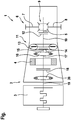
- the drive train 1 has a drive device 2, which in turn has an internal combustion engine 3, an electric machine and an output shaft 5.
- the drive device 2 is used to drive at least one wheel axle 6 of the motor vehicle, which is composed of two sub-axles 7 and 8, which are coupled via a differential gear 9 to the output shaft 5 of the drive device 2.
- the output shaft 5 is coupled to a transmission output shaft 10 of a gear change transmission 11 of the drive device 2, in particular rigid and / or permanent and / or coupled by means of an optional clutch 12.
- the gear change transmission 11 may, for example, have a torque converter 13, which may have a converter lock-up clutch 14.
- the gear change transmission 11 has a transmission input shaft 15, which is preferably permanently coupled to the torque converter 13.
- the transmission input shaft 15 may be directly or - as shown here - coupled via a damping device 16, for example a torsional vibration damper, with a machine shaft 17 of the electric machine 4, in particular rigid and / or permanent.
- the electric machine 4 may be arranged coaxially with the transmission input shaft 15 and / or the transmission output shaft 10.
- An operative connection between the internal combustion engine 3 and the electric machine 4 is adjustable by means of a clutch 18.
- the clutch 18 is in this case between a drive shaft 19 of the internal combustion engine 3 and the machine shaft 17 of the electric machine 4 before.
- a further damping device 20 may optionally be provided in the operative connection between the internal combustion engine 3 and the clutch 18.
- the damping device 20 is preferably designed as a dual mass flywheel.
- the internal combustion engine 3 In a first switching state of the clutch 18, the internal combustion engine 3 is decoupled from the electric machine 4. In a second switching state, however, it is coupled with her. Accordingly, the clutch 18 is opened in the first switching state, in particular fully open, and in the second switching state at least partially, preferably completely, closed. Under the full closing can be understood a closing of the clutch 18 with or without clutch overpressure.
Landscapes
- Engineering & Computer Science (AREA)
- Mechanical Engineering (AREA)
- Chemical & Material Sciences (AREA)
- Combustion & Propulsion (AREA)
- Transportation (AREA)
- Automation & Control Theory (AREA)
- General Engineering & Computer Science (AREA)
- Health & Medical Sciences (AREA)
- Biomedical Technology (AREA)
- General Health & Medical Sciences (AREA)
- Power Engineering (AREA)
- Hybrid Electric Vehicles (AREA)
- Electric Propulsion And Braking For Vehicles (AREA)
- Control Of Vehicle Engines Or Engines For Specific Uses (AREA)
Applications Claiming Priority (1)
| Application Number | Priority Date | Filing Date | Title |
|---|---|---|---|
| DE102017200977.2A DE102017200977A1 (de) | 2017-01-23 | 2017-01-23 | Verfahren zum Betreiben einer Antriebseinrichtung für ein Kraftfahrzeug sowie entsprechende Antriebseinrichtung |
Publications (2)
| Publication Number | Publication Date |
|---|---|
| EP3351449A1 true EP3351449A1 (fr) | 2018-07-25 |
| EP3351449B1 EP3351449B1 (fr) | 2023-09-20 |
Family
ID=60413067
Family Applications (1)
| Application Number | Title | Priority Date | Filing Date |
|---|---|---|---|
| EP17202475.4A Active EP3351449B1 (fr) | 2017-01-23 | 2017-11-20 | Procédé de fonctionnement d'un dispositif d'entraînement pour véhicule automobile et dispositif d'entraînement correspondant |
Country Status (4)
| Country | Link |
|---|---|
| US (1) | US10583731B2 (fr) |
| EP (1) | EP3351449B1 (fr) |
| CN (1) | CN108340910B (fr) |
| DE (1) | DE102017200977A1 (fr) |
Families Citing this family (3)
| Publication number | Priority date | Publication date | Assignee | Title |
|---|---|---|---|---|
| CN110395246B (zh) * | 2019-07-17 | 2021-08-13 | 吉利汽车研究院(宁波)有限公司 | 一种混动车辆的发动机启动控制方法、装置、设备和混动车辆 |
| DE102022201874A1 (de) | 2022-02-23 | 2023-08-24 | Magna Pt B.V. & Co. Kg | Verfahren zum Ein- und/oder Auslegen von Gängen eines Getriebes eines Kraftfahrzeugs |
| CN115042793B (zh) * | 2022-08-17 | 2022-11-11 | 中国重汽集团济南动力有限公司 | 一种混合动力系统换挡整车控制方法 |
Citations (4)
| Publication number | Priority date | Publication date | Assignee | Title |
|---|---|---|---|---|
| DE102007055826A1 (de) * | 2007-12-17 | 2009-06-18 | Zf Friedrichshafen Ag | Verfahren und Vorrichtung zum Betrieb eines Hybridantriebes eines Fahrzeugs |
| DE102007055828A1 (de) * | 2007-12-17 | 2009-06-18 | Zf Friedrichshafen Ag | Verfahren und Vorrichtung zum Betrieb eines Hybridfahrzeuges |
| DE102008002383A1 (de) * | 2008-06-12 | 2009-12-17 | Zf Friedrichshafen Ag | Verfahren zur Steuerung eines Hybridantriebsstrangs |
| EP3088228A2 (fr) * | 2014-11-19 | 2016-11-02 | Hyundai Motor Company | Appareil et procédé de contrôle de l'embrayage d'un moteur |
Family Cites Families (13)
| Publication number | Priority date | Publication date | Assignee | Title |
|---|---|---|---|---|
| JP3458795B2 (ja) * | 1999-10-08 | 2003-10-20 | トヨタ自動車株式会社 | ハイブリッド駆動装置 |
| JP3582521B2 (ja) * | 2002-08-13 | 2004-10-27 | 日産自動車株式会社 | 4輪駆動車両の駆動力制御装置 |
| DE602005001708T2 (de) | 2004-02-04 | 2008-05-21 | Renault S.A.S. | Verfahren zur Überwachung von Entscheidungen über Wechseln der Betriebsart eines stufenlosen Getriebes |
| JP4529940B2 (ja) * | 2006-05-02 | 2010-08-25 | 日産自動車株式会社 | ハイブリッド車両の伝動状態切り替え制御装置 |
| DE102007010770A1 (de) * | 2007-03-06 | 2008-09-11 | Robert Bosch Gmbh | Verfahren und Steuervorrichtung zum Durchführen eines Startens eines Verbrennungsmotors in einem Hybridfahrzeug |
| DE102006054740A1 (de) | 2006-11-21 | 2008-06-12 | Dr.Ing.H.C. F. Porsche Ag | Verfahren und Vorrichtung zum Zuschalten eines Verbrennungsmotors in einem Hybrid-Fahrzeugantrieb |
| DE102007001424B4 (de) | 2007-01-09 | 2017-07-27 | Dr. Ing. H.C. F. Porsche Aktiengesellschaft | Verfahren zum Starten eines Kolbenmotors, Hybrid-Antrieb für ein Kraftfahrzeug sowie Kraftfahrzeug mit Hybridantrieb |
| DE102011002742A1 (de) | 2011-01-17 | 2012-07-19 | Zf Friedrichshafen Ag | Verfahren und Steuergerät zum Betreiben eines Antriebsstrang eines Hybridfahrzeugs |
| DE102011079079A1 (de) | 2011-07-13 | 2013-01-17 | Zf Friedrichshafen Ag | Verfahren zur Steuerung eines Hybridantriebsstrangs eines Kraftfahrzeugs |
| DE102012208845A1 (de) | 2012-05-25 | 2013-11-28 | Robert Bosch Gmbh | Fahrzeug mit Rekuperationssystem |
| US9108615B2 (en) * | 2013-09-19 | 2015-08-18 | Borgwarner Inc. | Multimode clutch for a parallel hybrid vehicle |
| JP6260564B2 (ja) * | 2015-03-25 | 2018-01-17 | トヨタ自動車株式会社 | ハイブリッド車両の駆動装置 |
| KR101776524B1 (ko) * | 2016-09-05 | 2017-09-20 | 현대자동차주식회사 | 엔진클러치 체결상태 판단방법 |
-
2017
- 2017-01-23 DE DE102017200977.2A patent/DE102017200977A1/de not_active Withdrawn
- 2017-11-20 EP EP17202475.4A patent/EP3351449B1/fr active Active
- 2017-12-15 US US15/843,058 patent/US10583731B2/en active Active
-
2018
- 2018-01-22 CN CN201810060330.8A patent/CN108340910B/zh active Active
Patent Citations (4)
| Publication number | Priority date | Publication date | Assignee | Title |
|---|---|---|---|---|
| DE102007055826A1 (de) * | 2007-12-17 | 2009-06-18 | Zf Friedrichshafen Ag | Verfahren und Vorrichtung zum Betrieb eines Hybridantriebes eines Fahrzeugs |
| DE102007055828A1 (de) * | 2007-12-17 | 2009-06-18 | Zf Friedrichshafen Ag | Verfahren und Vorrichtung zum Betrieb eines Hybridfahrzeuges |
| DE102008002383A1 (de) * | 2008-06-12 | 2009-12-17 | Zf Friedrichshafen Ag | Verfahren zur Steuerung eines Hybridantriebsstrangs |
| EP3088228A2 (fr) * | 2014-11-19 | 2016-11-02 | Hyundai Motor Company | Appareil et procédé de contrôle de l'embrayage d'un moteur |
Also Published As
| Publication number | Publication date |
|---|---|
| CN108340910A (zh) | 2018-07-31 |
| US20180208045A1 (en) | 2018-07-26 |
| DE102017200977A1 (de) | 2018-07-26 |
| US10583731B2 (en) | 2020-03-10 |
| CN108340910B (zh) | 2021-01-29 |
| EP3351449B1 (fr) | 2023-09-20 |
Similar Documents
| Publication | Publication Date | Title |
|---|---|---|
| DE102007001424B4 (de) | Verfahren zum Starten eines Kolbenmotors, Hybrid-Antrieb für ein Kraftfahrzeug sowie Kraftfahrzeug mit Hybridantrieb | |
| DE102010037677A1 (de) | Verfahren zum Steuern des Starts eines Motors in einem Kraftfahrzeug | |
| DE102007062796A1 (de) | Verfahren zum Betreiben einer Hybridantriebsvorrichtung | |
| DE102009045485A1 (de) | Verfahren zum Betreiben einer Antriebsvorrichtung, Antriebsvorrichtung | |
| WO2017202419A1 (fr) | Procédé de fonctionnement d'une chaîne cinématique d'un véhicule hybride et chaîne cinématique d'un véhicule hybride | |
| WO2010010041A1 (fr) | Procédé de fonctionnement d'une chaîne de propulsion | |
| DE102010049931A1 (de) | Verfahren zur Erhöhung des Kupplungsmoments | |
| DE102017200981B3 (de) | Verfahren zum Betreiben einer Antriebseinrichtung für ein Kraftfahrzeug sowie entsprechende Antriebseinrichtung | |
| DE102014200253A1 (de) | Verfahren zum Starten einer Verbrennungskraftmaschine eines Hybridfahrzeuges und Hybridfahrzeug | |
| EP3351449B1 (fr) | Procédé de fonctionnement d'un dispositif d'entraînement pour véhicule automobile et dispositif d'entraînement correspondant | |
| EP3501870B1 (fr) | Procédé de fonctionnement d'un dispositif d'entraînement pour un véhicule automobile ainsi que dispositif d'entraînement correspondant | |
| DE10204981A1 (de) | Verfahren zum Betrieb eines Antriebssystems für ein Kraftfahrzeug | |
| DE102012220478A1 (de) | Verfahren sowie Steuerungseinrichtung zum Betreiben eines Hybridfahrzeugs | |
| EP2718593B1 (fr) | Procédé pour faire fonctionner un dispositif d'entraînement ainsi que dispositif pour le fonctionnement du dispositif d'entraînement | |
| EP3351446B1 (fr) | Procédé de fonctionnement d'un dispositif d'entraînement pour véhicule automobile et dispositif d'entraînement correspondant | |
| EP3277552A1 (fr) | Procédé permettant de faire fonctionner un dispositif d'entraînement pour un véhicule automobile et dispositif d'entraînement correspondant | |
| EP3263382B1 (fr) | Procédé d'entraînement d'un dispositif d'entraînement et dispositif d'entraînement correspondant | |
| DE102018205710A1 (de) | Verfahren und Steuerungseinrichtung zum Betreiben eines Antriebsstrangs | |
| DE102008040661B4 (de) | Verfahren zum Betreiben eines Antriebsstrangs | |
| DE102018204908A1 (de) | Verfahren zum Betrieb eines Antriebsstranges eines Kraftfahrzeugs, und Antriebsstrangmodul eines solchen Kraftfahrzeugs | |
| EP3972866B1 (fr) | Procédé pour faire fonctionner un dispositif d'entraînement conçu pour un véhicule automobile, et dispositif d'entraînement correspondant | |
| DE102017214787A1 (de) | Impulsstart in einem Hybrid-Antriebsstrang | |
| DE102017220072A1 (de) | Verfahren beim Betrieb eines Hybridfahrzeugs | |
| DE10332668A1 (de) | Schaltbares Antriebssystem, Komponenten und Betriebsverfahren dafür | |
| DE10301534A1 (de) | Verfahren zum Betrieb eines Antriebsstrangs eines Kraftfahrzeugs |
Legal Events
| Date | Code | Title | Description |
|---|---|---|---|
| PUAI | Public reference made under article 153(3) epc to a published international application that has entered the european phase |
Free format text: ORIGINAL CODE: 0009012 |
|
| STAA | Information on the status of an ep patent application or granted ep patent |
Free format text: STATUS: THE APPLICATION HAS BEEN PUBLISHED |
|
| AK | Designated contracting states |
Kind code of ref document: A1 Designated state(s): AL AT BE BG CH CY CZ DE DK EE ES FI FR GB GR HR HU IE IS IT LI LT LU LV MC MK MT NL NO PL PT RO RS SE SI SK SM TR |
|
| AX | Request for extension of the european patent |
Extension state: BA ME |
|
| STAA | Information on the status of an ep patent application or granted ep patent |
Free format text: STATUS: REQUEST FOR EXAMINATION WAS MADE |
|
| RIC1 | Information provided on ipc code assigned before grant |
Ipc: B60W 20/50 20160101ALI20180523BHEP Ipc: B60W 10/11 20120101ALI20180523BHEP Ipc: B60W 10/02 20060101ALI20180523BHEP Ipc: B60W 20/40 20160101AFI20180523BHEP Ipc: B60K 6/48 20071001ALI20180523BHEP Ipc: B60W 10/08 20060101ALI20180523BHEP Ipc: B60K 6/387 20071001ALI20180523BHEP Ipc: B60W 10/06 20060101ALI20180523BHEP Ipc: B60W 50/02 20120101ALN20180523BHEP Ipc: B60K 6/547 20071001ALI20180523BHEP |
|
| 17P | Request for examination filed |
Effective date: 20190125 |
|
| RBV | Designated contracting states (corrected) |
Designated state(s): AL AT BE BG CH CY CZ DE DK EE ES FI FR GB GR HR HU IE IS IT LI LT LU LV MC MK MT NL NO PL PT RO RS SE SI SK SM TR |
|
| STAA | Information on the status of an ep patent application or granted ep patent |
Free format text: STATUS: EXAMINATION IS IN PROGRESS |
|
| 17Q | First examination report despatched |
Effective date: 20211119 |
|
| GRAP | Despatch of communication of intention to grant a patent |
Free format text: ORIGINAL CODE: EPIDOSNIGR1 |
|
| STAA | Information on the status of an ep patent application or granted ep patent |
Free format text: STATUS: GRANT OF PATENT IS INTENDED |
|
| RIC1 | Information provided on ipc code assigned before grant |
Ipc: B60W 50/02 20120101ALN20230428BHEP Ipc: B60W 20/50 20160101ALI20230428BHEP Ipc: B60K 6/387 20071001ALI20230428BHEP Ipc: B60K 6/547 20071001ALI20230428BHEP Ipc: B60K 6/48 20071001ALI20230428BHEP Ipc: B60W 10/11 20120101ALI20230428BHEP Ipc: B60W 10/08 20060101ALI20230428BHEP Ipc: B60W 10/06 20060101ALI20230428BHEP Ipc: B60W 10/02 20060101ALI20230428BHEP Ipc: B60W 20/40 20160101AFI20230428BHEP |
|
| INTG | Intention to grant announced |
Effective date: 20230525 |
|
| P01 | Opt-out of the competence of the unified patent court (upc) registered |
Effective date: 20230529 |
|
| GRAS | Grant fee paid |
Free format text: ORIGINAL CODE: EPIDOSNIGR3 |
|
| GRAA | (expected) grant |
Free format text: ORIGINAL CODE: 0009210 |
|
| STAA | Information on the status of an ep patent application or granted ep patent |
Free format text: STATUS: THE PATENT HAS BEEN GRANTED |
|
| AK | Designated contracting states |
Kind code of ref document: B1 Designated state(s): AL AT BE BG CH CY CZ DE DK EE ES FI FR GB GR HR HU IE IS IT LI LT LU LV MC MK MT NL NO PL PT RO RS SE SI SK SM TR |
|
| REG | Reference to a national code |
Ref country code: GB Ref legal event code: FG4D Free format text: NOT ENGLISH |
|
| REG | Reference to a national code |
Ref country code: CH Ref legal event code: EP |
|
| REG | Reference to a national code |
Ref country code: IE Ref legal event code: FG4D Free format text: LANGUAGE OF EP DOCUMENT: GERMAN |
|
| REG | Reference to a national code |
Ref country code: DE Ref legal event code: R096 Ref document number: 502017015391 Country of ref document: DE |
|
| REG | Reference to a national code |
Ref country code: LT Ref legal event code: MG9D |
|
| PG25 | Lapsed in a contracting state [announced via postgrant information from national office to epo] |
Ref country code: GR Free format text: LAPSE BECAUSE OF FAILURE TO SUBMIT A TRANSLATION OF THE DESCRIPTION OR TO PAY THE FEE WITHIN THE PRESCRIBED TIME-LIMIT Effective date: 20231221 |
|
| REG | Reference to a national code |
Ref country code: NL Ref legal event code: MP Effective date: 20230920 |
|
| PG25 | Lapsed in a contracting state [announced via postgrant information from national office to epo] |
Ref country code: SE Free format text: LAPSE BECAUSE OF FAILURE TO SUBMIT A TRANSLATION OF THE DESCRIPTION OR TO PAY THE FEE WITHIN THE PRESCRIBED TIME-LIMIT Effective date: 20230920 Ref country code: RS Free format text: LAPSE BECAUSE OF FAILURE TO SUBMIT A TRANSLATION OF THE DESCRIPTION OR TO PAY THE FEE WITHIN THE PRESCRIBED TIME-LIMIT Effective date: 20230920 Ref country code: NO Free format text: LAPSE BECAUSE OF FAILURE TO SUBMIT A TRANSLATION OF THE DESCRIPTION OR TO PAY THE FEE WITHIN THE PRESCRIBED TIME-LIMIT Effective date: 20231220 Ref country code: LV Free format text: LAPSE BECAUSE OF FAILURE TO SUBMIT A TRANSLATION OF THE DESCRIPTION OR TO PAY THE FEE WITHIN THE PRESCRIBED TIME-LIMIT Effective date: 20230920 Ref country code: LT Free format text: LAPSE BECAUSE OF FAILURE TO SUBMIT A TRANSLATION OF THE DESCRIPTION OR TO PAY THE FEE WITHIN THE PRESCRIBED TIME-LIMIT Effective date: 20230920 Ref country code: HR Free format text: LAPSE BECAUSE OF FAILURE TO SUBMIT A TRANSLATION OF THE DESCRIPTION OR TO PAY THE FEE WITHIN THE PRESCRIBED TIME-LIMIT Effective date: 20230920 Ref country code: GR Free format text: LAPSE BECAUSE OF FAILURE TO SUBMIT A TRANSLATION OF THE DESCRIPTION OR TO PAY THE FEE WITHIN THE PRESCRIBED TIME-LIMIT Effective date: 20231221 Ref country code: FI Free format text: LAPSE BECAUSE OF FAILURE TO SUBMIT A TRANSLATION OF THE DESCRIPTION OR TO PAY THE FEE WITHIN THE PRESCRIBED TIME-LIMIT Effective date: 20230920 |
|
| PG25 | Lapsed in a contracting state [announced via postgrant information from national office to epo] |
Ref country code: NL Free format text: LAPSE BECAUSE OF FAILURE TO SUBMIT A TRANSLATION OF THE DESCRIPTION OR TO PAY THE FEE WITHIN THE PRESCRIBED TIME-LIMIT Effective date: 20230920 |
|
| PG25 | Lapsed in a contracting state [announced via postgrant information from national office to epo] |
Ref country code: IS Free format text: LAPSE BECAUSE OF FAILURE TO SUBMIT A TRANSLATION OF THE DESCRIPTION OR TO PAY THE FEE WITHIN THE PRESCRIBED TIME-LIMIT Effective date: 20240120 |
|
| PG25 | Lapsed in a contracting state [announced via postgrant information from national office to epo] |
Ref country code: ES Free format text: LAPSE BECAUSE OF FAILURE TO SUBMIT A TRANSLATION OF THE DESCRIPTION OR TO PAY THE FEE WITHIN THE PRESCRIBED TIME-LIMIT Effective date: 20230920 |
|
| PG25 | Lapsed in a contracting state [announced via postgrant information from national office to epo] |
Ref country code: SM Free format text: LAPSE BECAUSE OF FAILURE TO SUBMIT A TRANSLATION OF THE DESCRIPTION OR TO PAY THE FEE WITHIN THE PRESCRIBED TIME-LIMIT Effective date: 20230920 Ref country code: RO Free format text: LAPSE BECAUSE OF FAILURE TO SUBMIT A TRANSLATION OF THE DESCRIPTION OR TO PAY THE FEE WITHIN THE PRESCRIBED TIME-LIMIT Effective date: 20230920 Ref country code: IS Free format text: LAPSE BECAUSE OF FAILURE TO SUBMIT A TRANSLATION OF THE DESCRIPTION OR TO PAY THE FEE WITHIN THE PRESCRIBED TIME-LIMIT Effective date: 20240120 Ref country code: ES Free format text: LAPSE BECAUSE OF FAILURE TO SUBMIT A TRANSLATION OF THE DESCRIPTION OR TO PAY THE FEE WITHIN THE PRESCRIBED TIME-LIMIT Effective date: 20230920 Ref country code: EE Free format text: LAPSE BECAUSE OF FAILURE TO SUBMIT A TRANSLATION OF THE DESCRIPTION OR TO PAY THE FEE WITHIN THE PRESCRIBED TIME-LIMIT Effective date: 20230920 Ref country code: CZ Free format text: LAPSE BECAUSE OF FAILURE TO SUBMIT A TRANSLATION OF THE DESCRIPTION OR TO PAY THE FEE WITHIN THE PRESCRIBED TIME-LIMIT Effective date: 20230920 Ref country code: PT Free format text: LAPSE BECAUSE OF FAILURE TO SUBMIT A TRANSLATION OF THE DESCRIPTION OR TO PAY THE FEE WITHIN THE PRESCRIBED TIME-LIMIT Effective date: 20240122 Ref country code: SK Free format text: LAPSE BECAUSE OF FAILURE TO SUBMIT A TRANSLATION OF THE DESCRIPTION OR TO PAY THE FEE WITHIN THE PRESCRIBED TIME-LIMIT Effective date: 20230920 |
|
| PG25 | Lapsed in a contracting state [announced via postgrant information from national office to epo] |
Ref country code: PL Free format text: LAPSE BECAUSE OF FAILURE TO SUBMIT A TRANSLATION OF THE DESCRIPTION OR TO PAY THE FEE WITHIN THE PRESCRIBED TIME-LIMIT Effective date: 20230920 Ref country code: IT Free format text: LAPSE BECAUSE OF FAILURE TO SUBMIT A TRANSLATION OF THE DESCRIPTION OR TO PAY THE FEE WITHIN THE PRESCRIBED TIME-LIMIT Effective date: 20230920 |
|
| REG | Reference to a national code |
Ref country code: DE Ref legal event code: R097 Ref document number: 502017015391 Country of ref document: DE |
|
| REG | Reference to a national code |
Ref country code: CH Ref legal event code: PL |
|
| PG25 | Lapsed in a contracting state [announced via postgrant information from national office to epo] |
Ref country code: MC Free format text: LAPSE BECAUSE OF FAILURE TO SUBMIT A TRANSLATION OF THE DESCRIPTION OR TO PAY THE FEE WITHIN THE PRESCRIBED TIME-LIMIT Effective date: 20230920 |
|
| PG25 | Lapsed in a contracting state [announced via postgrant information from national office to epo] |
Ref country code: DK Free format text: LAPSE BECAUSE OF FAILURE TO SUBMIT A TRANSLATION OF THE DESCRIPTION OR TO PAY THE FEE WITHIN THE PRESCRIBED TIME-LIMIT Effective date: 20230920 |
|
| PG25 | Lapsed in a contracting state [announced via postgrant information from national office to epo] |
Ref country code: LU Free format text: LAPSE BECAUSE OF NON-PAYMENT OF DUE FEES Effective date: 20231120 |
|
| PG25 | Lapsed in a contracting state [announced via postgrant information from national office to epo] |
Ref country code: CH Free format text: LAPSE BECAUSE OF NON-PAYMENT OF DUE FEES Effective date: 20231130 |
|
| PLBE | No opposition filed within time limit |
Free format text: ORIGINAL CODE: 0009261 |
|
| STAA | Information on the status of an ep patent application or granted ep patent |
Free format text: STATUS: NO OPPOSITION FILED WITHIN TIME LIMIT |
|
| PG25 | Lapsed in a contracting state [announced via postgrant information from national office to epo] |
Ref country code: MC Free format text: LAPSE BECAUSE OF FAILURE TO SUBMIT A TRANSLATION OF THE DESCRIPTION OR TO PAY THE FEE WITHIN THE PRESCRIBED TIME-LIMIT Effective date: 20230920 Ref country code: LU Free format text: LAPSE BECAUSE OF NON-PAYMENT OF DUE FEES Effective date: 20231120 Ref country code: DK Free format text: LAPSE BECAUSE OF FAILURE TO SUBMIT A TRANSLATION OF THE DESCRIPTION OR TO PAY THE FEE WITHIN THE PRESCRIBED TIME-LIMIT Effective date: 20230920 Ref country code: CH Free format text: LAPSE BECAUSE OF NON-PAYMENT OF DUE FEES Effective date: 20231130 |
|
| REG | Reference to a national code |
Ref country code: BE Ref legal event code: MM Effective date: 20231130 |
|
| 26N | No opposition filed |
Effective date: 20240621 |
|
| GBPC | Gb: european patent ceased through non-payment of renewal fee |
Effective date: 20231220 |
|
| REG | Reference to a national code |
Ref country code: IE Ref legal event code: MM4A |
|
| PG25 | Lapsed in a contracting state [announced via postgrant information from national office to epo] |
Ref country code: IE Free format text: LAPSE BECAUSE OF NON-PAYMENT OF DUE FEES Effective date: 20231120 |
|
| PG25 | Lapsed in a contracting state [announced via postgrant information from national office to epo] |
Ref country code: GB Free format text: LAPSE BECAUSE OF NON-PAYMENT OF DUE FEES Effective date: 20231220 |
|
| PG25 | Lapsed in a contracting state [announced via postgrant information from national office to epo] |
Ref country code: BE Free format text: LAPSE BECAUSE OF NON-PAYMENT OF DUE FEES Effective date: 20231130 |
|
| PG25 | Lapsed in a contracting state [announced via postgrant information from national office to epo] |
Ref country code: FR Free format text: LAPSE BECAUSE OF NON-PAYMENT OF DUE FEES Effective date: 20231120 |
|
| PG25 | Lapsed in a contracting state [announced via postgrant information from national office to epo] |
Ref country code: SI Free format text: LAPSE BECAUSE OF FAILURE TO SUBMIT A TRANSLATION OF THE DESCRIPTION OR TO PAY THE FEE WITHIN THE PRESCRIBED TIME-LIMIT Effective date: 20230920 |
|
| PG25 | Lapsed in a contracting state [announced via postgrant information from national office to epo] |
Ref country code: SI Free format text: LAPSE BECAUSE OF FAILURE TO SUBMIT A TRANSLATION OF THE DESCRIPTION OR TO PAY THE FEE WITHIN THE PRESCRIBED TIME-LIMIT Effective date: 20230920 Ref country code: IE Free format text: LAPSE BECAUSE OF NON-PAYMENT OF DUE FEES Effective date: 20231120 Ref country code: GB Free format text: LAPSE BECAUSE OF NON-PAYMENT OF DUE FEES Effective date: 20231220 Ref country code: FR Free format text: LAPSE BECAUSE OF NON-PAYMENT OF DUE FEES Effective date: 20231120 Ref country code: BE Free format text: LAPSE BECAUSE OF NON-PAYMENT OF DUE FEES Effective date: 20231130 |
|
| PG25 | Lapsed in a contracting state [announced via postgrant information from national office to epo] |
Ref country code: BG Free format text: LAPSE BECAUSE OF FAILURE TO SUBMIT A TRANSLATION OF THE DESCRIPTION OR TO PAY THE FEE WITHIN THE PRESCRIBED TIME-LIMIT Effective date: 20230920 |
|
| PG25 | Lapsed in a contracting state [announced via postgrant information from national office to epo] |
Ref country code: BG Free format text: LAPSE BECAUSE OF FAILURE TO SUBMIT A TRANSLATION OF THE DESCRIPTION OR TO PAY THE FEE WITHIN THE PRESCRIBED TIME-LIMIT Effective date: 20230920 |
|
| REG | Reference to a national code |
Ref country code: AT Ref legal event code: MM01 Ref document number: 1613221 Country of ref document: AT Kind code of ref document: T Effective date: 20231120 |
|
| PG25 | Lapsed in a contracting state [announced via postgrant information from national office to epo] |
Ref country code: AT Free format text: LAPSE BECAUSE OF NON-PAYMENT OF DUE FEES Effective date: 20231120 |
|
| PG25 | Lapsed in a contracting state [announced via postgrant information from national office to epo] |
Ref country code: AT Free format text: LAPSE BECAUSE OF NON-PAYMENT OF DUE FEES Effective date: 20231120 |
|
| PG25 | Lapsed in a contracting state [announced via postgrant information from national office to epo] |
Ref country code: CY Free format text: LAPSE BECAUSE OF FAILURE TO SUBMIT A TRANSLATION OF THE DESCRIPTION OR TO PAY THE FEE WITHIN THE PRESCRIBED TIME-LIMIT; INVALID AB INITIO Effective date: 20171120 |
|
| PG25 | Lapsed in a contracting state [announced via postgrant information from national office to epo] |
Ref country code: HU Free format text: LAPSE BECAUSE OF FAILURE TO SUBMIT A TRANSLATION OF THE DESCRIPTION OR TO PAY THE FEE WITHIN THE PRESCRIBED TIME-LIMIT; INVALID AB INITIO Effective date: 20171120 |
|
| PG25 | Lapsed in a contracting state [announced via postgrant information from national office to epo] |
Ref country code: TR Free format text: LAPSE BECAUSE OF FAILURE TO SUBMIT A TRANSLATION OF THE DESCRIPTION OR TO PAY THE FEE WITHIN THE PRESCRIBED TIME-LIMIT Effective date: 20230920 |
|
| PGFP | Annual fee paid to national office [announced via postgrant information from national office to epo] |
Ref country code: DE Payment date: 20251130 Year of fee payment: 9 |