EP3351709A1 - Zusammensetzbares profil für einen gartenzaun - Google Patents
Zusammensetzbares profil für einen gartenzaun Download PDFInfo
- Publication number
- EP3351709A1 EP3351709A1 EP18152462.0A EP18152462A EP3351709A1 EP 3351709 A1 EP3351709 A1 EP 3351709A1 EP 18152462 A EP18152462 A EP 18152462A EP 3351709 A1 EP3351709 A1 EP 3351709A1
- Authority
- EP
- European Patent Office
- Prior art keywords
- profile
- cross
- assemblable
- base
- garden
- Prior art date
- Legal status (The legal status is an assumption and is not a legal conclusion. Google has not performed a legal analysis and makes no representation as to the accuracy of the status listed.)
- Granted
Links
Images
Classifications
-
- E—FIXED CONSTRUCTIONS
- E04—BUILDING
- E04H—BUILDINGS OR LIKE STRUCTURES FOR PARTICULAR PURPOSES; SWIMMING OR SPLASH BATHS OR POOLS; MASTS; FENCING; TENTS OR CANOPIES, IN GENERAL
- E04H17/00—Fencing, e.g. fences, enclosures, corrals
- E04H17/14—Fences constructed of rigid elements, e.g. with additional wire fillings or with posts
- E04H17/1413—Post-and-rail fences, e.g. without vertical cross-members
- E04H17/1417—Post-and-rail fences, e.g. without vertical cross-members with vertical cross-members
-
- E—FIXED CONSTRUCTIONS
- E04—BUILDING
- E04H—BUILDINGS OR LIKE STRUCTURES FOR PARTICULAR PURPOSES; SWIMMING OR SPLASH BATHS OR POOLS; MASTS; FENCING; TENTS OR CANOPIES, IN GENERAL
- E04H17/00—Fencing, e.g. fences, enclosures, corrals
- E04H17/14—Fences constructed of rigid elements, e.g. with additional wire fillings or with posts
- E04H17/16—Fences constructed of rigid elements, e.g. with additional wire fillings or with posts using prefabricated panel-like elements, e.g. wired frames
- E04H17/161—Fences constructed of rigid elements, e.g. with additional wire fillings or with posts using prefabricated panel-like elements, e.g. wired frames using wire panels
- E04H17/164—Fences constructed of rigid elements, e.g. with additional wire fillings or with posts using prefabricated panel-like elements, e.g. wired frames using wire panels occultation devices therefor, e.g. slats, fence liners or panels blocking view therethrough
-
- E—FIXED CONSTRUCTIONS
- E04—BUILDING
- E04H—BUILDINGS OR LIKE STRUCTURES FOR PARTICULAR PURPOSES; SWIMMING OR SPLASH BATHS OR POOLS; MASTS; FENCING; TENTS OR CANOPIES, IN GENERAL
- E04H17/00—Fencing, e.g. fences, enclosures, corrals
- E04H17/14—Fences constructed of rigid elements, e.g. with additional wire fillings or with posts
- E04H17/1413—Post-and-rail fences, e.g. without vertical cross-members
- E04H17/1417—Post-and-rail fences, e.g. without vertical cross-members with vertical cross-members
- E04H17/1426—Picket fences
Definitions
- the present invention relates to fences for providing a visual screening, for example around a garden.
- the invention relates to cross-profiles for clamping in garden slats which can be fitted into a pre-provided garden fence.
- garden slats or garden panels have been developed which can be slid into a pre-provided wiring around the plot.
- Such wiring dependent on the manufacturer, is manufactured with varying dimensions.
- the distance between two vertical wires can be 50 or 55 mm. Accordingly, the manufacturer of the garden slats must also provide varying dimensions for the garden slats to be slided in.
- EP 2 924 193 describes a clamping element which supports the garden slats and also shows a top profile to enclose the upper side of the garden slats.
- one or more cross-profiles called 'nose profiles' in jargon, are provided to sufficiently robustly enclose the garden slats .
- Such cross-profiles are mounted into horizontal passages or loops provided thereto, and exert a transversal pressure on the garden slats.
- a cross-profile should be easy to use, possess sufficient mechanical strength to realise a desired clamping of the garden slats and to satisfy visual expectations of a consumer.
- the present invention seeks to provide a solution for one or more of aforementioned problems or shortcomings.
- the invention provides an assemblable cross-profile for garden fencing.
- the invention provides an assemblable cross-profile 1, 2 comprising a base profile 1 and an aspect profile 2, and one or more spacing elements 121, 122, 13, 141, 142, 22, 23 to affix said base profile 1 and said aspect profile 2 at two or more distances from each other.
- a means one or more than one segment.
- the citation of numerical intervals by the end points comprises all whole numbers, fractions and/or real numbers between the end points, including these end points.
- base profile and “aspect profile” should be regarded as interchangeable.
- the term “aspect profile” is used to preferably denote a profile which is to be provided with a desired visual aspect, such as shape, colour, relief, for example.
- the term “base profile” is used to denote a profile which serves as base for affixing said aspect profile.
- the terms “spacing element” or “spacing elements” should be regarded as an element or a set of elements which are provided to bear said base profile and said aspect profile at two or more distances from each other.
- affix should be understood as synonymous for the term “to bear” or “to position” and should be understood as assembling said base profile and said aspect profile at a fixed distance with respect to each other. More specifically, the term “affix” refers to assembling said base profile and said aspect profile at a fixed distance from respective base areas with respect to each other.
- the invention provides an assemblable cross-profile 1, 2 comprising a base profile 1 and an aspect profile 2, and one or more spacing elements 121, 122, 13, 141, 142, 22, 23 to affix said base profile 1 and said aspect profile 2 at two or more distances from each other.
- said assemblable cross-profile relates to a cross-profile for a garden fence wherein a series of slats is provided between a series of vertical wirings.
- the present invention provides an assemblable cross-profile according to the first aspect of the invention, wherein said base profile 1 and said aspect profile 2 are both provided with one or more spacing elements 121, 122, 13, 141, 142, 22, 23 to affix said base profile 1 and said aspect profile 2 at two or more distances from each other.
- the present invention provides an assemblable cross-profile according to the first aspect of the invention, wherein said spacing elements 121, 122, 13, 141, 142, 22, 23 are provided to affix said base profile 1 and said aspect profile 2 at two to four, and preferably two or three, varying distances from each other.
- said spacing elements are provided to affix said base profile 1 and said aspect profile 2 at two varying distances from each other.
- the present invention provides an assemblable cross-profile according to the first aspect of the invention, wherein said aspect profile 2 is provided with a protrusion 22 and wherein said base profile 1 is provided with a recess 13 for receiving said protrusion 22, or vice versa.
- a protrusion and recess preferably interconnect and offer a simple embodiment to mutually anchor or affix said base profile and said aspect profile.
- the present invention provides an assemblable cross-profile according to the first aspect of the invention, wherein said protrusion 22 is provided with a resistance element 23 and wherein said recess 13 is provided with a complementary resistance element 141, 142.
- Said resistance elements allow said base profile and said aspect profile to be affixed at two or more discrete, predetermined distances from each other. In this way, the cross-profile can be provided to satisfy two or more dimensions, preferably two or more commercially common dimensions.
- the present invention provides an assemblable cross-profile according to the first aspect of the invention, wherein said resistance elements 141, 142, 23 have a round cross section.
- said base profile and said aspect profile can simply slide into and out of each other from a first position at the level of resistance element 141 to a second position at the level of resistance element 142.
- the present invention provides an assemblable cross-profile according to the first aspect of the invention, wherein said base profile 1 and said aspect profile 2 are manufactured from a thermoplastic material. More preferably, said spacing elements are manufactured from a thermoplastic material, and still more preferably said base profile and said aspect profile, including spacing elements and resistance elements, are completely manufactured from a thermoplastic material. Thermoplastic materials are readily mouldable by means of extrusion and are less rigid than thermosetting or metallic materials. Because of this, the resistance elements are flexible during assembly of said base profile and aspect profile, as a result of which a transition can be simply made from a first to a second position without causing damage to the spacing elements in doing so.
- said base profile and said aspect profile are manufactured from polyvinylchloride (PVC) with a certain amount of softening agent sufficient to guarantee the required flexibility of the resistance elements.
- PVC polyvinylchloride
- the required amount of softening agent also depends on the thickness of the resistance elements.
- said base profile and said aspect profile are manufactured from a material having the same composition and mechanical properties, such as flexibility.
- the present invention provides an assemblable cross-profile according to the first aspect of the invention, wherein said base profile 1 is provided with two raised edges 111, 112.
- said two raised edges 111, 112 are provided at an angle ⁇ less than 90°, such as indicated in Figure 3 . More preferably, said angle ⁇ is chosen between 45° and 75° and still more preferably between 50° and 70°. Most preferably, said angle ⁇ is equal to 52°, 54°, 56°, 58°, 60°, 62°, 64°, 66° or 68°, or any value located therein between.
- the present invention provides an assemblable cross-profile according to the first aspect of the invention, wherein the raised edges 111, 112 of said base profile 1 are provided with a raised edge 113, 114 at an angle of ⁇ .
- the angle ⁇ is chosen such that, in the second state in which base profile and aspect profile lie closer to each other, the raised edges 113, 114 of the base profile and 211, 212 of the aspect profile come to lie contiguously in a same plane.
- the closed cross section is realised.
- the present invention provides an assemblable cross-profile according to the first aspect of the invention, wherein the raised edges 111, 112 of said base profile 1 are curved. Still more preferably, said raised edges 111, 112 are round. This offers as an advantage that, upon assembling base profile and aspect profile, the slanted raised edges of the aspect profile can touch the raised edges of the base profile at any predetermined distance between base profile and aspect profile whatsoever.
- the present invention provides an assemblable cross-profile according to the first aspect of the invention, wherein said aspect profile 2 is provided with two raised edges 211, 212.
- said two raised edges 211, 212 are provided at an angle ⁇ greater than 90°, such as indicated in Figure 3 . More preferably, said angle ⁇ is chosen between 105° and 135° and, still more preferably, between 110° and 130°. Most preferably, said angle ⁇ is equal to 112°, 114°, 116°, 118°, 120°, 122°, 124°, 126° or 128°, or any value located therein between.
- the present invention provides an assemblable cross-profile according to the first aspect of the invention, wherein angles ⁇ and ⁇ are supplementary angles. It is meant therewith that the sum of ⁇ and ⁇ is equal to 180°, or at least is equal to approximately 180°. In this way, the raised edges of base profile and aspect profile are the extension of each other, so forming two closed sides of a trapezium.
- the present invention provides an assemblable cross-profile according to the first aspect of the invention, wherein said base profile 1 and said aspect profile 2 are provided with a varying thickness.
- the present invention provides an assemblable cross-profile according to the first aspect of the invention, wherein said base profile 1 is provided with a greater thickness than said aspect profile 2. Because said base profile and said aspect profile are manufactured from a same material with the same mechanical properties, such as flexibility, the raised edges of the aspect profile with a thinner thickness will nevertheless flex more simply opposite with respect to the raised edges of the base profile. In this way it can be assured that the raised edges interconnect closely.
- the invention provides a kit comprising:
- the invention provides a fence with cross-profile 1, 2 according to the first aspect of the invention.
- the invention provides a mould for making an assemblable cross-profile 1, 2 according to the first aspect of the invention.
- the invention provides a method for making an assemblable cross-profile 1, 2 according to the first aspect of the invention, wherein a base profile 1 and an aspect profile 2 are separately extruded, and wherein said base profile 1 and said aspect profile 2 are both provided with spacing elements 121, 122, 13, 141, 142, 22, 23 to affix said base profile 1 and said aspect profile 2 at two or more distances from each other.
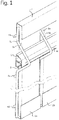
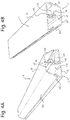
- Figure 1 shows schematically a perspective of an assembled cross-profile 1, 2 for enclosing a series of garden slats 3 in a garden fence 4, 5.
- the garden fence comprises a series of horizontal wirings 4a, 4b, 4c, 4d, ... and a series of vertical wirings 5a, 5b, ... between which a series of garden slats 3a, 3b, ... is clamped.
- the framework 4, 5 shows a horizontal loop for bearing a cross-profile 1, 2.
- the garden slats 3a, 3b, ... are supported at the bottom by means of a clamping clip 6a, 6b, ... and are clamped at the top by means of a span 7.
- the assembled cross-profile 1, 2 shows a base profile 1 and an aspect profile 2, which in assembled state designate a closed, trapezoid cross section.
- the shortest base 21 of the assembled cross-profile 1, 2 is directed towards the wiring 4b.
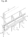
- Figure 2A shows an alternative embodiment for the embodiment according to Figure 1 , wherein the horizontal loop for bearing the assembled cross-profile 1, 2 is provided with two horizontal wirings, 4b and 4c.
- the wiring 4b and 4c For such an embodiment of the wiring 4, 5, it can be opted to bear the assembled cross-profile 1, 2 with the longest base 1 directed towards the wiring 4b, 4c.
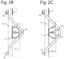
- Figures 2B and 2C show in side view a detail of the embodiments according to Figure. 1 and Figure. 2A , respectively.
- the assembled cross-profile 1, 2 can be provided with a height D1 or D2.
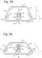
- FIG. 3A shows in further detail a side view of the assembled cross-profile 1, 2 in assembled state.
- the base profile 1 is shown with the aspect profile 2 beared therein at an established, fixed distance.
- base profile 1 and aspect profile 2 are provided with spacing means, 121, 122, 13, 141, 142 and 22, 23, respectively.
- the protrusion 22 stands upright on the base area 21 of the aspect profile 2 and is provided with a spherical edge 23 at its extremity.
- a recess 13 is formed by means of two raised edges 121 and 122 standing upright on the base area 11 of the base profile 1.
- the recess 13 has a width corresponding to, and preferably not greater than, the width of the protrusion 22 of the aspect profile 2.
- the width of the protrusion 22 is even implemented in a slightly narrower dimension with respect to the width of the recess 13, e.g. 1.3 mm as opposed to 1.5 mm. In this way, no permanent stresses are exerted by the protrusion 22 on the raised edges 121 and 122.
- the recess 13 is provided with two locally widened parts 141 and 142 with a width to clamp the spherical edge 23.
- the diameter of the spherical edge 13 corresponds with the diameter of the two local cavities 141, 142.
- the raised edges 121 and 122 of the recess 13 are manufactured from a flexible material such as PVC with plasticizer, for example, such that the spherical edge 23 can be moved from the position at the level of widened part 142 to the position at the level of widened part 141, or vice versa, by slightly pressing the two raised edges 121 and 122 outwards during the transition.
- the height of the assembled cross-profile can be readily adapted to the dimensions of the horizontal loop of the fence.
- it can be opted to slide the base profile 1 and the aspect profile 2 away from each other in the longitudinal direction, and to subsequently slide these in the desired position again in the longitudinal direction.
- the base profile 1 is provided with raised edges 111, 112 at an angle of ⁇ .
- the base area 21 of the aspect profile 2 is provided with a slanted raised edge 211, 212 at an angle of ⁇ .
- care is taken to ensure that angles ⁇ and ⁇ are supplementary. That is, the sum of ⁇ and ⁇ is 180.
- the raised edges 111, 112 and 211, 212 come to lie contiguously in a same plane. In this way, a closed trapezoid cross section can be obtained.
- a closed cross section is important for preventing ingress of rain water, biological or other material in the cross-profile.
- the aspect profile 2 and the base profile 1 are preferably manufactured from a same, lightly flexible material. However, the thickness of the aspect profile 2 is less than the thickness of the base profile 1, e.g. 1.0 mm as opposed to 1.1 mm.
- the cross-profile 1, 2 is fixed in the closest state, that is, the spherical edge 23 is beared at the level of the local, spherical cavity 141, the raised edges 211, 212 will fold slightly outwards. This will increase the angle ⁇ .
- the raised edges 111, 112 are each provided with a raised edge 113, 114 at an angle of ⁇ . The angle ⁇ is chosen such that in the closest state, the raised edges 113, 114 and 211, 212 come to lie contiguously in a same plane.
- the closed cross section is realised.
- FIG. 3B the cross-profile is shown in a closest, assembled state.
- the raised edges 211, 212 of the aspect profile 2 are pressed slightly outwards in this regard, which is expressed by a larger angle ⁇ ', wherein ⁇ ' > ⁇ .
- the raised edges 211, 212 come to abut the raised edges 113, 114 of the base profile 1, so forming a closed trapezoid cross section.
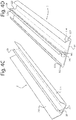
- Figures 4A and 4B show the assembled cross-profiles 1, 2 in varying perspectives.
- Figures 4C and 4D show in perspective the aspect profile 2 and the base profile 1, respectively.
Landscapes
- Engineering & Computer Science (AREA)
- Architecture (AREA)
- Civil Engineering (AREA)
- Structural Engineering (AREA)
- Fencing (AREA)
Applications Claiming Priority (1)
| Application Number | Priority Date | Filing Date | Title |
|---|---|---|---|
| BE2017/5032A BE1024490B1 (nl) | 2017-01-20 | 2017-01-20 | Samenstelbaar dwarsprofiel voor tuinbedrading |
Publications (3)
| Publication Number | Publication Date |
|---|---|
| EP3351709A1 true EP3351709A1 (de) | 2018-07-25 |
| EP3351709B1 EP3351709B1 (de) | 2024-09-25 |
| EP3351709C0 EP3351709C0 (de) | 2024-09-25 |
Family
ID=57962964
Family Applications (1)
| Application Number | Title | Priority Date | Filing Date |
|---|---|---|---|
| EP18152462.0A Active EP3351709B1 (de) | 2017-01-20 | 2018-01-19 | Zusammensetzbares profil für einen gartenzaun |
Country Status (2)
| Country | Link |
|---|---|
| EP (1) | EP3351709B1 (de) |
| BE (1) | BE1024490B1 (de) |
Cited By (1)
| Publication number | Priority date | Publication date | Assignee | Title |
|---|---|---|---|---|
| FR3088947A1 (fr) * | 2018-11-28 | 2020-05-29 | Geplast | Dispositif d'occultation notamment pour la réalisation de clôtures ainsi qu'un procédé de montage d'un tel dispositif |
Citations (5)
| Publication number | Priority date | Publication date | Assignee | Title |
|---|---|---|---|---|
| FR1105961A (fr) * | 1954-06-02 | 1955-12-09 | Cie Ind Des Telephones | Dispositif de liaison de panneaux |
| FR1252603A (fr) * | 1955-02-12 | 1961-02-03 | Dispositif d'assemblage de parois ou analogues | |
| US3385567A (en) * | 1965-11-05 | 1968-05-28 | Reynolds Metals Co | Railing constructions and parts therefor or the like |
| DE2027609A1 (de) * | 1970-06-05 | 1971-12-09 | Weserstahl KG Dr. Wiesner u. Co, 4950 Minden | Klemmverbindung |
| DE202004009649U1 (de) * | 2004-06-18 | 2004-11-11 | Obermeier, Peter | Verbindungssystem |
-
2017
- 2017-01-20 BE BE2017/5032A patent/BE1024490B1/nl active IP Right Grant
-
2018
- 2018-01-19 EP EP18152462.0A patent/EP3351709B1/de active Active
Patent Citations (5)
| Publication number | Priority date | Publication date | Assignee | Title |
|---|---|---|---|---|
| FR1105961A (fr) * | 1954-06-02 | 1955-12-09 | Cie Ind Des Telephones | Dispositif de liaison de panneaux |
| FR1252603A (fr) * | 1955-02-12 | 1961-02-03 | Dispositif d'assemblage de parois ou analogues | |
| US3385567A (en) * | 1965-11-05 | 1968-05-28 | Reynolds Metals Co | Railing constructions and parts therefor or the like |
| DE2027609A1 (de) * | 1970-06-05 | 1971-12-09 | Weserstahl KG Dr. Wiesner u. Co, 4950 Minden | Klemmverbindung |
| DE202004009649U1 (de) * | 2004-06-18 | 2004-11-11 | Obermeier, Peter | Verbindungssystem |
Cited By (2)
| Publication number | Priority date | Publication date | Assignee | Title |
|---|---|---|---|---|
| FR3088947A1 (fr) * | 2018-11-28 | 2020-05-29 | Geplast | Dispositif d'occultation notamment pour la réalisation de clôtures ainsi qu'un procédé de montage d'un tel dispositif |
| EP3660244A1 (de) | 2018-11-28 | 2020-06-03 | Geplast | Verdunkelungsvorrichtung insbesondere für die herstellung von zäunen sowie montageverfahren einer solchen vorrichtung |
Also Published As
| Publication number | Publication date |
|---|---|
| EP3351709B1 (de) | 2024-09-25 |
| EP3351709C0 (de) | 2024-09-25 |
| BE1024490B1 (nl) | 2018-03-07 |
Similar Documents
| Publication | Publication Date | Title |
|---|---|---|
| EP2678509B1 (de) | Rahmenverbindung | |
| US20080179580A1 (en) | Pocket rail construction | |
| EP3889372A1 (de) | Satz aus einer stützstruktur, einer befestigungsvorrichtung und einem ersten und zweiten paneel | |
| US5645270A (en) | Plastic component connection system | |
| EP2351896B1 (de) | Säulensystem und Schirmvorrichtung mit einem oder mehreren Säulensystemen | |
| EP3351709B1 (de) | Zusammensetzbares profil für einen gartenzaun | |
| EP3103936A1 (de) | Modulare metallabdeckung für gebäude | |
| AU662995B2 (en) | Picture or poster frame | |
| CN104797169A (zh) | 框架构件 | |
| KR100865371B1 (ko) | 휀스 | |
| US20200005685A1 (en) | Graphic display frame and extension | |
| EP3477805B1 (de) | Kabelleiterecke | |
| CN203821962U (zh) | 一种可快捷安装的木塑围栏 | |
| KR101083692B1 (ko) | 비닐하우스의 서까래 보강장치 | |
| KR101081618B1 (ko) | 펜스 | |
| US20040168385A1 (en) | Coping for swimming pool, particularly an above-ground swimming pool, and process for its production | |
| US20060196618A1 (en) | Blind slat structure | |
| EP3981936A1 (de) | Bausatz zur herstellung eines garten-drahtpaneels und tragklammer für eine latte eines solchen garten-drahtpaneels | |
| EP2857631A1 (de) | Pergola-Markise | |
| KR101753123B1 (ko) | 비닐하우스의 비닐 고정용 덮개바 및 이를 이용한 비닐하우스 시공방법 | |
| KR20190050028A (ko) | 베니션 블라인드용 블라인드 슬랫 및 이의 제조방법 | |
| KR200468276Y1 (ko) | 압출바를 이용한 개선된 형태의 조립식 기둥 | |
| CN210164745U (zh) | 一种型材板连接结构及相关家具和装修 | |
| KR100866026B1 (ko) | 농작물 재배용 하우스 골조 결속구조 | |
| US12180736B2 (en) | Warp resistant fence panel |
Legal Events
| Date | Code | Title | Description |
|---|---|---|---|
| PUAI | Public reference made under article 153(3) epc to a published international application that has entered the european phase |
Free format text: ORIGINAL CODE: 0009012 |
|
| STAA | Information on the status of an ep patent application or granted ep patent |
Free format text: STATUS: THE APPLICATION HAS BEEN PUBLISHED |
|
| AK | Designated contracting states |
Kind code of ref document: A1 Designated state(s): AL AT BE BG CH CY CZ DE DK EE ES FI FR GB GR HR HU IE IS IT LI LT LU LV MC MK MT NL NO PL PT RO RS SE SI SK SM TR |
|
| AX | Request for extension of the european patent |
Extension state: BA ME |
|
| STAA | Information on the status of an ep patent application or granted ep patent |
Free format text: STATUS: REQUEST FOR EXAMINATION WAS MADE |
|
| 17P | Request for examination filed |
Effective date: 20190125 |
|
| RBV | Designated contracting states (corrected) |
Designated state(s): AL AT BE BG CH CY CZ DE DK EE ES FI FR GB GR HR HU IE IS IT LI LT LU LV MC MK MT NL NO PL PT RO RS SE SI SK SM TR |
|
| STAA | Information on the status of an ep patent application or granted ep patent |
Free format text: STATUS: EXAMINATION IS IN PROGRESS |
|
| 17Q | First examination report despatched |
Effective date: 20211206 |
|
| REG | Reference to a national code |
Ref country code: DE Ref legal event code: R079 Free format text: PREVIOUS MAIN CLASS: E04H0017140000 Ipc: E04H0017160000 Ref country code: DE Ref legal event code: R079 Ref document number: 602018074652 Country of ref document: DE Free format text: PREVIOUS MAIN CLASS: E04H0017140000 Ipc: E04H0017160000 |
|
| GRAP | Despatch of communication of intention to grant a patent |
Free format text: ORIGINAL CODE: EPIDOSNIGR1 |
|
| STAA | Information on the status of an ep patent application or granted ep patent |
Free format text: STATUS: GRANT OF PATENT IS INTENDED |
|
| RIC1 | Information provided on ipc code assigned before grant |
Ipc: E04H 17/14 20060101ALI20240328BHEP Ipc: E04H 17/16 20060101AFI20240328BHEP |
|
| INTG | Intention to grant announced |
Effective date: 20240415 |
|
| GRAS | Grant fee paid |
Free format text: ORIGINAL CODE: EPIDOSNIGR3 |
|
| GRAA | (expected) grant |
Free format text: ORIGINAL CODE: 0009210 |
|
| STAA | Information on the status of an ep patent application or granted ep patent |
Free format text: STATUS: THE PATENT HAS BEEN GRANTED |
|
| AK | Designated contracting states |
Kind code of ref document: B1 Designated state(s): AL AT BE BG CH CY CZ DE DK EE ES FI FR GB GR HR HU IE IS IT LI LT LU LV MC MK MT NL NO PL PT RO RS SE SI SK SM TR |
|
| REG | Reference to a national code |
Ref country code: GB Ref legal event code: FG4D |
|
| REG | Reference to a national code |
Ref country code: CH Ref legal event code: EP |
|
| REG | Reference to a national code |
Ref country code: DE Ref legal event code: R096 Ref document number: 602018074652 Country of ref document: DE |
|
| REG | Reference to a national code |
Ref country code: IE Ref legal event code: FG4D |
|
| U01 | Request for unitary effect filed |
Effective date: 20241022 |
|
| U07 | Unitary effect registered |
Designated state(s): AT BE BG DE DK EE FI FR IT LT LU LV MT NL PT RO SE SI Effective date: 20241105 |
|
| PG25 | Lapsed in a contracting state [announced via postgrant information from national office to epo] |
Ref country code: NO Free format text: LAPSE BECAUSE OF FAILURE TO SUBMIT A TRANSLATION OF THE DESCRIPTION OR TO PAY THE FEE WITHIN THE PRESCRIBED TIME-LIMIT Effective date: 20241225 |
|
| PG25 | Lapsed in a contracting state [announced via postgrant information from national office to epo] |
Ref country code: GR Free format text: LAPSE BECAUSE OF FAILURE TO SUBMIT A TRANSLATION OF THE DESCRIPTION OR TO PAY THE FEE WITHIN THE PRESCRIBED TIME-LIMIT Effective date: 20241226 |
|
| PG25 | Lapsed in a contracting state [announced via postgrant information from national office to epo] |
Ref country code: RS Free format text: LAPSE BECAUSE OF FAILURE TO SUBMIT A TRANSLATION OF THE DESCRIPTION OR TO PAY THE FEE WITHIN THE PRESCRIBED TIME-LIMIT Effective date: 20241225 |
|
| PG25 | Lapsed in a contracting state [announced via postgrant information from national office to epo] |
Ref country code: RS Free format text: LAPSE BECAUSE OF FAILURE TO SUBMIT A TRANSLATION OF THE DESCRIPTION OR TO PAY THE FEE WITHIN THE PRESCRIBED TIME-LIMIT Effective date: 20241225 Ref country code: NO Free format text: LAPSE BECAUSE OF FAILURE TO SUBMIT A TRANSLATION OF THE DESCRIPTION OR TO PAY THE FEE WITHIN THE PRESCRIBED TIME-LIMIT Effective date: 20241225 Ref country code: GR Free format text: LAPSE BECAUSE OF FAILURE TO SUBMIT A TRANSLATION OF THE DESCRIPTION OR TO PAY THE FEE WITHIN THE PRESCRIBED TIME-LIMIT Effective date: 20241226 |
|
| U20 | Renewal fee for the european patent with unitary effect paid |
Year of fee payment: 8 Effective date: 20250128 |
|
| PG25 | Lapsed in a contracting state [announced via postgrant information from national office to epo] |
Ref country code: IS Free format text: LAPSE BECAUSE OF FAILURE TO SUBMIT A TRANSLATION OF THE DESCRIPTION OR TO PAY THE FEE WITHIN THE PRESCRIBED TIME-LIMIT Effective date: 20250125 |
|
| PG25 | Lapsed in a contracting state [announced via postgrant information from national office to epo] |
Ref country code: SM Free format text: LAPSE BECAUSE OF FAILURE TO SUBMIT A TRANSLATION OF THE DESCRIPTION OR TO PAY THE FEE WITHIN THE PRESCRIBED TIME-LIMIT Effective date: 20240925 |
|
| PG25 | Lapsed in a contracting state [announced via postgrant information from national office to epo] |
Ref country code: ES Free format text: LAPSE BECAUSE OF FAILURE TO SUBMIT A TRANSLATION OF THE DESCRIPTION OR TO PAY THE FEE WITHIN THE PRESCRIBED TIME-LIMIT Effective date: 20240925 |
|
| PG25 | Lapsed in a contracting state [announced via postgrant information from national office to epo] |
Ref country code: CZ Free format text: LAPSE BECAUSE OF FAILURE TO SUBMIT A TRANSLATION OF THE DESCRIPTION OR TO PAY THE FEE WITHIN THE PRESCRIBED TIME-LIMIT Effective date: 20240925 Ref country code: PL Free format text: LAPSE BECAUSE OF FAILURE TO SUBMIT A TRANSLATION OF THE DESCRIPTION OR TO PAY THE FEE WITHIN THE PRESCRIBED TIME-LIMIT Effective date: 20240925 |
|
| PG25 | Lapsed in a contracting state [announced via postgrant information from national office to epo] |
Ref country code: SK Free format text: LAPSE BECAUSE OF FAILURE TO SUBMIT A TRANSLATION OF THE DESCRIPTION OR TO PAY THE FEE WITHIN THE PRESCRIBED TIME-LIMIT Effective date: 20240925 |
|
| PLBE | No opposition filed within time limit |
Free format text: ORIGINAL CODE: 0009261 |
|
| STAA | Information on the status of an ep patent application or granted ep patent |
Free format text: STATUS: NO OPPOSITION FILED WITHIN TIME LIMIT |
|
| REG | Reference to a national code |
Ref country code: CH Ref legal event code: PL |
|
| 26N | No opposition filed |
Effective date: 20250626 |
|
| PG25 | Lapsed in a contracting state [announced via postgrant information from national office to epo] |
Ref country code: MC Free format text: LAPSE BECAUSE OF FAILURE TO SUBMIT A TRANSLATION OF THE DESCRIPTION OR TO PAY THE FEE WITHIN THE PRESCRIBED TIME-LIMIT Effective date: 20240925 |
|
| GBPC | Gb: european patent ceased through non-payment of renewal fee |
Effective date: 20250119 |
|
| PG25 | Lapsed in a contracting state [announced via postgrant information from national office to epo] |
Ref country code: GB Free format text: LAPSE BECAUSE OF NON-PAYMENT OF DUE FEES Effective date: 20250119 |
|
| PG25 | Lapsed in a contracting state [announced via postgrant information from national office to epo] |
Ref country code: CH Free format text: LAPSE BECAUSE OF NON-PAYMENT OF DUE FEES Effective date: 20250131 |
|
| PG25 | Lapsed in a contracting state [announced via postgrant information from national office to epo] |
Ref country code: HR Free format text: LAPSE BECAUSE OF FAILURE TO SUBMIT A TRANSLATION OF THE DESCRIPTION OR TO PAY THE FEE WITHIN THE PRESCRIBED TIME-LIMIT Effective date: 20240925 |
|
| PG25 | Lapsed in a contracting state [announced via postgrant information from national office to epo] |
Ref country code: IE Free format text: LAPSE BECAUSE OF NON-PAYMENT OF DUE FEES Effective date: 20250119 |
|
| U20 | Renewal fee for the european patent with unitary effect paid |
Year of fee payment: 9 Effective date: 20260129 |