EP3351784B1 - Élément d'espacement et moteur à combustion interne - Google Patents
Élément d'espacement et moteur à combustion interne Download PDFInfo
- Publication number
- EP3351784B1 EP3351784B1 EP16857511.6A EP16857511A EP3351784B1 EP 3351784 B1 EP3351784 B1 EP 3351784B1 EP 16857511 A EP16857511 A EP 16857511A EP 3351784 B1 EP3351784 B1 EP 3351784B1
- Authority
- EP
- European Patent Office
- Prior art keywords
- circumferential side
- cylinder
- cylinder head
- cylinder liner
- outer circumferential
- Prior art date
- Legal status (The legal status is an assumption and is not a legal conclusion. Google has not performed a legal analysis and makes no representation as to the accuracy of the status listed.)
- Active
Links
Images


Classifications
-
- F—MECHANICAL ENGINEERING; LIGHTING; HEATING; WEAPONS; BLASTING
- F02—COMBUSTION ENGINES; HOT-GAS OR COMBUSTION-PRODUCT ENGINE PLANTS
- F02B—INTERNAL-COMBUSTION PISTON ENGINES; COMBUSTION ENGINES IN GENERAL
- F02B23/00—Other engines characterised by special shape or construction of combustion chambers to improve operation
-
- F—MECHANICAL ENGINEERING; LIGHTING; HEATING; WEAPONS; BLASTING
- F02—COMBUSTION ENGINES; HOT-GAS OR COMBUSTION-PRODUCT ENGINE PLANTS
- F02B—INTERNAL-COMBUSTION PISTON ENGINES; COMBUSTION ENGINES IN GENERAL
- F02B23/00—Other engines characterised by special shape or construction of combustion chambers to improve operation
- F02B23/08—Other engines characterised by special shape or construction of combustion chambers to improve operation with positive ignition
-
- F—MECHANICAL ENGINEERING; LIGHTING; HEATING; WEAPONS; BLASTING
- F02—COMBUSTION ENGINES; HOT-GAS OR COMBUSTION-PRODUCT ENGINE PLANTS
- F02F—CYLINDERS, PISTONS OR CASINGS, FOR COMBUSTION ENGINES; ARRANGEMENTS OF SEALINGS IN COMBUSTION ENGINES
- F02F11/00—Arrangements of sealings in combustion engines
-
- F—MECHANICAL ENGINEERING; LIGHTING; HEATING; WEAPONS; BLASTING
- F02—COMBUSTION ENGINES; HOT-GAS OR COMBUSTION-PRODUCT ENGINE PLANTS
- F02F—CYLINDERS, PISTONS OR CASINGS, FOR COMBUSTION ENGINES; ARRANGEMENTS OF SEALINGS IN COMBUSTION ENGINES
- F02F11/00—Arrangements of sealings in combustion engines
- F02F11/002—Arrangements of sealings in combustion engines involving cylinder heads
-
- F—MECHANICAL ENGINEERING; LIGHTING; HEATING; WEAPONS; BLASTING
- F02—COMBUSTION ENGINES; HOT-GAS OR COMBUSTION-PRODUCT ENGINE PLANTS
- F02F—CYLINDERS, PISTONS OR CASINGS, FOR COMBUSTION ENGINES; ARRANGEMENTS OF SEALINGS IN COMBUSTION ENGINES
- F02F11/00—Arrangements of sealings in combustion engines
- F02F11/005—Arrangements of sealings in combustion engines involving cylinder liners
-
- Y—GENERAL TAGGING OF NEW TECHNOLOGICAL DEVELOPMENTS; GENERAL TAGGING OF CROSS-SECTIONAL TECHNOLOGIES SPANNING OVER SEVERAL SECTIONS OF THE IPC; TECHNICAL SUBJECTS COVERED BY FORMER USPC CROSS-REFERENCE ART COLLECTIONS [XRACs] AND DIGESTS
- Y02—TECHNOLOGIES OR APPLICATIONS FOR MITIGATION OR ADAPTATION AGAINST CLIMATE CHANGE
- Y02T—CLIMATE CHANGE MITIGATION TECHNOLOGIES RELATED TO TRANSPORTATION
- Y02T10/00—Road transport of goods or passengers
- Y02T10/10—Internal combustion engine [ICE] based vehicles
- Y02T10/12—Improving ICE efficiencies
-
- Y—GENERAL TAGGING OF NEW TECHNOLOGICAL DEVELOPMENTS; GENERAL TAGGING OF CROSS-SECTIONAL TECHNOLOGIES SPANNING OVER SEVERAL SECTIONS OF THE IPC; TECHNICAL SUBJECTS COVERED BY FORMER USPC CROSS-REFERENCE ART COLLECTIONS [XRACs] AND DIGESTS
- Y10—TECHNICAL SUBJECTS COVERED BY FORMER USPC
- Y10S—TECHNICAL SUBJECTS COVERED BY FORMER USPC CROSS-REFERENCE ART COLLECTIONS [XRACs] AND DIGESTS
- Y10S277/00—Seal for a joint or juncture
- Y10S277/935—Seal made of a particular material
- Y10S277/944—Elastomer or plastic
Definitions
- the present invention relates to an internal combustion engine.
- Gas engines which are operated by burning gaseous fuels (fuel gases) such as natural gas and city gas are known. Theses gas engines can obtain high efficiency and high output. Therefore, gas engines are widely used mainly for power generation engines for regular and emergency use, engines for construction machines, engines mounted on ships, vehicles, and so on.
- gaseous fuels fuel gases
- natural gas and city gas gaseous fuels
- gas engines can obtain high efficiency and high output. Therefore, gas engines are widely used mainly for power generation engines for regular and emergency use, engines for construction machines, engines mounted on ships, vehicles, and so on.
- JP 2010-150983 A describes a premixed combustion type auxiliary chamber gas engine.
- the gas engine disclosed in Patent Document 1 when a piston approaches a compression top dead center in a main combustion chamber and fuel gas in the main combustion chamber is compressed, the fuel gas supplied into an auxiliary chamber is ignited by a spark of a spark plug provided in the auxiliary chamber. Therefore, a flame is generated from the auxiliary chamber, and this flame is injected from a mouthpiece provided in the auxiliary chamber into the main combustion chamber. Then, a mixed gas in the main combustion chamber is ignited by this flame.
- a gas engine generally includes a cylinder block (crankcase) and a cylinder head.
- the cylinder block has a hole which opens toward the cylinder head and accommodates a piston.
- a cylindrical cylinder liner which forms a sliding surface for the piston is installed inside this hole.
- the cylinder head is fastened to the cylinder block by a bolt or the like and occludes an opening of the cylinder block at that time.
- a space surrounded by the cylinder head, the cylinder liner and the piston serves as a main combustion chamber to which mixed gas is supplied.
- a seal member such as a gasket for sealing the main combustion chamber is provided between the cylinder block and the cylinder head.
- the seal member is sandwiched between the cylinder block on an outer circumferential side of the cylinder liner or the cylinder liner and the cylinder head.
- the seal member is sandwiched between the cylinder head and the cylinder block and pressed by an axial force of the bolt fastening the cylinder head and the cylinder block and exerts high sealing performance.
- GB 1 166 370 A , GB 1 124 160 A and US 2015/144089 A1 disclose cylinder head seal members.
- US 4 548 165 A discloses an internal combustion engine in accordance with the preamble of independent claim 1, which comprises an engine block having mounted thereon a cylinder head and a cylinder head gasket interposed between the engine block and the cylinder head, this gasket having cylinder holes of a diameter substantially greater than the cylinder bore, these cylinder holes of the gasket having inserted thereinto continuous or split annular shaping rims.
- Each shaping rim is fashioned as a deformable body with an element for attachment thereof to the cylinder head gasket.
- the size of the deformable body of the shaping rim is commensurable with the volume of a gas space enclosed by the cylinder head, cylinder head gasket, engine block and the continuation of the wall of the cylinder bore, the deformable body of the shaping rim engaging with the surfaces of the cylinder head and engine block confined between the cylinder hole of the gasket and the continuation of the wall of the cylinder bore of the internal combustion engine.
- a first aspect of the present invention relates to an internal combustion engine as defined in claim 1.
- the gap member is disposed in the gap between the cylinder head and the cylinder liner on the inner circumferential side of the seal portion, it is possible to suppress a fuel from entering this gap. Therefore, it is possible to suppress the fuel that has entered the gap from remaining without being burned during fuel combustion in the internal combustion engine and to suppress the lubricating oil from entering the gap and inducing abnormal combustion.
- the gap member has a lower Young's modulus than the seal portion. Therefore, when a pressing force is applied by fastening the cylinder body and the cylinder head with a bolt or the like, a repulsive force generated at the seal portion is larger than a repulsive force generated by the gap member being fitted therebetween.
- a fastening force for fastening the cylinder body and the cylinder head can act mainly through the seal portion rather than through the gap member. Accordingly, it is possible to prevent a shearing force from acting on the cylinder liner by the fastening force and to reduce breakage of the cylinder liner.
- the gap member is formed in an annular belt shape corresponding to the gap between the cylinder head and the cylinder liner.
- the gap member is also disposed in a space between the two stepped portions, the space that the fuel enters can be further reduced. Therefore, it is possible to further suppress the fuel that has entered the gap from remaining without being burned during the fuel combustion in the main combustion chamber . Furthermore, since a curved portion is formed, positioning of the gap member with respect to the gap can be-performed easily.
- the internal combustion engine of the first aspect may be formed so that, in the internal combustion engine, a mixed gas in which fuel and air are mixed is supplied to a combustion chamber defined by being surrounded by the cylinder liner, the cylinder head, and the piston.
- the mixed gas In an internal combustion engine such as a gas engine in which a mixed gas in which fuel and air are mixed in advance is supplied to a combustion chamber, the mixed gas easily enters the gap between the cylinder head and the cylinder liner. In such a constitution, the entering of the mixed gas into the gap can be suppressed by disposing the gap member in the gap.
- the gap member is disposed in a gap between the cylinder head and the cylinder liner on an inner circumferential side of the seal portion.
- Fig. 1 is a cross-sectional view taken along a center axis of a cylinder and showing a constitution around a cylinder head of a gas engine according to an illustrative example.
- an engine (internal combustion engine) 10 includes at least a cylinder block (cylinder body) 20, a cylinder head 30A, and an auxiliary chamber member 40.
- the engine 10 in the example is a gas engine which is operated by combusting a gaseous fuel (fuel gas) such as natural gas or city gas.
- the engine 10 in the example is a stationary auxiliary chamber type gas engine used for power generation equipment and so on.
- a hole 20h which opens in a head surface 20f facing the cylinder head 30A is formed in a cylinder block 20.
- a cylindrical cylinder liner 21 is disposed inside the hole 20h.
- the cylinder liner 21 is integrally formed with a flange portion 21f.
- the flange portion 21f is formed at one end 21a close to the cylinder head 30A.
- the flange portion 21 f is also formed so that a diameter thereof increases toward an outer circumferential side around a center axis C of the cylinder liner 21 (hereinafter, simply referred to as an outer circumferential side).
- the cylinder block 20 has an accommodating groove 20m at an opening edge of the hole 20h.
- the accommodating groove 20m is formed in an annular shape to accommodate the flange portion 21f of the cylinder liner 21.
- the cylinder liner 21 is positioned with respect to the cylinder block 20 by accommodating the flange portion 21f in the accommodating groove 20m of the cylinder block 20.
- the cylinder liner 21 accommodates a piston 22 therein.
- the piston 22 is formed to be linearly reciprocable in a direction in which the center axis C of the cylinder liner 21 extends (hereinafter, referred to as a "cylinder axial direction") while being guided by the cylinder liner 21.
- the piston 22 is connected to a crankshaft 24 accommodated in a crankcase (not shown) via a connecting rod 23.
- the connecting rod 23 is rotatably connected to the piston 22 via a pin 25.
- the connecting rod 23 is further rotatably connected to the crankshaft 24 via a pin 26. Accordingly, when the piston 22 linearly moves in the cylinder axial direction within the cylinder liner 21, a linear motion of the piston 22 is transmitted to the crankshaft 24 by the connecting rod 23 and converted into a rotational motion of the crankshaft 24.
- the cylinder head 30A is fastened to a head surface 20f of the cylinder block 20 by a bolt (not shown) or the like. Therefore, the cylinder head 30A closes an opening 21o of the one end 21a of the cylinder liner 21.
- a roof surface 31 having a flat shape, a hemispherical shape, or a curved surface shape orthogonal to the center axis C of the cylinder liner 21 is formed on a surface of the cylinder head 30A which faces the cylinder block 20 side.
- the roof surface 31 is formed in a region facing the cylinder liner 21.
- a main combustion chamber (combustion chamber) 33 is defined by the above-described cylinder liner 21, the roof surface 31 of the cylinder head 30A, and the piston 22.
- An intake port 34 and an exhaust port 35 are formed in the cylinder head 30A.
- the intake port 34 and the exhaust port 35 are formed at intervals in a circumferential direction around the center axis C of the cylinder liner 21. End portions 34a and 35a of the intake port 34 and the exhaust port 35 on the main combustion chamber 33 open to the roof surface 31 and face the main combustion chamber 33.
- the intake port 34 communicates with a mixed gas supply source (not shown).
- a mixed gas supply source By this mixed gas supply source, a premixed gas in which air is premixed with a combustion gas can be supplied to the intake port 34.
- an intake valve 36 is provided at an end 34a on a side close to the main combustion chamber 33.
- the intake valve 36 can be displaced from a closed position to an open position by a valve drive mechanism (not shown).
- the mixed gas supplied from the mixed gas supply source is supplied from the intake port 34 to the main combustion chamber 33 by displacing the intake valve 36 from the closed position to the open position.
- the exhaust port 35 is connected to an exhaust gas flow path (not shown).
- an exhaust valve 37 is provided at the end portion 35a close to the main combustion chamber 33.
- the auxiliary chamber member 40 includes an auxiliary chamber holder 42 and an auxiliary chamber mouthpiece 43.
- the auxiliary chamber holder 42 is provided inside the cylinder head 30A.
- a center axis of the auxiliary chamber holder 42 is provided on an extension line of the center axis C of the cylinder liner 21.
- the auxiliary chamber mouthpiece 43 is provided to protrude from a center of the roof surface 31 of the cylinder head 30A into the main combustion chamber 33.
- the auxiliary chamber mouthpiece 43 is formed in a hollow shape, and an internal space thereof is an auxiliary chamber 41.
- a fuel gas is supplied to the auxiliary chamber 41 from the outside.
- a spark plug 45 is provided in the auxiliary chamber holder 42.
- the fuel gas supplied from the outside into the auxiliary chamber 41 is ignited and burned to generate a flame by generating a spark from the spark plug 45.
- the flame generated by this ignition is injected into the main combustion chamber 33 from the auxiliary chamber mouthpiece 43.
- the mixed gas supplied into the main combustion chamber 33 through the intake port 34 (refer to Fig. 1 ) is ignited and burned by this flame.
- the piston 22 linearly reciprocates in the cylinder axial direction of the cylinder liner 21, and the engine 10 is driven.
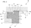
- Fig. 2 is an enlarged cross-sectional view showing a joining structure of the cylinder block and the cylinder head of the internal combustion engine.
- the cylinder liner 21 has an outer circumferential side end surface 21p and an inner circumferential side end surface 21q.
- the outer circumferential side end surface 21p and the inner circumferential side end surface 21q face the cylinder head 30A in the cylinder axial direction.
- the outer circumferential side end surface 21p and the inner circumferential side end surface 21q are formed to be orthogonal to the center axis C of the cylinder liner 21.
- the outer circumferential side end surface 21p is provided on an outer circumferential side of the cylinder liner 21, that is, at a position far from the center axis C.
- the outer circumferential side end surface 21p is formed to include at least a surface of the flange portion 21 f facing the cylinder head 30A side.
- the inner circumferential side end surface 21q is provided on an inner circumferential side of the cylinder liner 21, that is, at a position close to the center axis C. In other words, the inner circumferential side end surface 21q is formed at a position closer to the center axis C than the flange portion 21f.
- the inner circumferential side end surface 21q is formed at a position protruding toward the cylinder head 30A side of the outer circumferential side end surface 21p.
- a stepped portion 21r extending in the cylinder axial direction is formed between the outer circumferential side end surface 21p and the inner circumferential side end surface 21q.
- the cylinder head 30A includes an inner circumferential side opposing surface 31q and an outer circumferential side opposing surface 31p which face the inner circumferential side end surface 21q and the outer circumferential side end surface 21p of the cylinder liner 21, respectively.
- the inner circumferential side opposing surface 31q and the outer circumferential side opposing surface 31p are formed to be orthogonal to the center axis C.
- the inner circumferential side opposing surface 31q is formed on an outer circumferential side of the roof surface 31.
- the outer circumferential side opposing surface 31p is formed on an outer circumferential side of the inner circumferential side opposing surface 31q.
- the outer circumferential side opposing surface 31p is formed at a position protruding toward the cylinder liner 21 side of the inner circumferential side opposing surface 31q.
- a stepped portion 31r extending in the cylinder axial direction is formed between the inner circumferential side opposing surface 31q and the outer circumferential side opposing surface 31p.
- a height of the stepped portion 31r between the inner circumferential side opposing surface 31q and the outer circumferential side opposing surface 31p is smaller than a height of the stepped portion 21r between the outer circumferential side end surface 21p and the inner circumferential side end surface 21q.
- a gasket (seal portion) 41A is provided between the cylinder liner 21 and the cylinder head 30A.
- the gasket 41A is disposed to surround an outer circumferential side of the opening 21o of the cylinder liner 21. More specifically, the gasket 41A is sandwiched between the outer circumferential side end surface 21p and the outer circumferential side opposing surface 31p to seal between the outer circumferential side end surface 21p of the cylinder liner 21 and the outer circumferential side opposing surface 31p of the cylinder head 30A.
- the gasket 41A is sandwiched between the cylinder head 30A and the cylinder block 20 together with the flange portion 21f by an axial force of a bolt (not shown) which fastens the cylinder head 30A and the cylinder block 20. Accordingly, the gasket 41A is slightly compressed and deformed and exhibits a high sealing property.
- a slight gap S is formed between the inner circumferential side end surface 21q and the inner circumferential side opposing surface 31q.
- the gap S is set to a dimension in which the cylinder head 30A and the cylinder liner 21 do not come in direct contact when assembled with the gasket 41A interposed therebetween and is also set to a size of, for example, 1mm or less which is a flame quenching distance.
- the engine 10 includes a gap member 50 disposed in the gap S.
- the gap member 50 is formed in a shape corresponding to a shape of the gap S. More specifically, the gap member 50 is formed in an annular shape continuing in a circumferential direction along the inner circumferential side end surface 21q of the cylinder liner 21 when seen in the cylinder axial direction. Further, the gap member 50 in the example is formed in a solid belt shape (in other words, a sheet shape) having a thickness substantially equal to the gap S. The gap member 50 in the example is formed to have the same thickness as the gap S in molding. However, the gap member 50 formed in this manner is disposed to be slightly crushed by the inner circumferential side opposing surface 31q and the inner circumferential side end surface 21q due to thermal expansion and bolt tightening.
- the gap member 50 is formed of a material which is more flexible and has a lower Young's modulus than the cylinder head 30A, the cylinder liner 21, and the gasket 41A.
- the gap member 50 has sufficient heat resistance to withstand a temperature rise due to combustion of the premixed gas in the main combustion chamber 33.
- a ratio of the Young's modulus of the gasket 41A to the Young's modulus of the gap member 50 may be in a range of 1:0.001 to 1:0.7.
- the material of the gap member 50 is selected according to a temperature in the main combustion chamber 33 and a flow of force to the cylinder liner 21.
- the ratio of the Young's modulus of the gasket 41A to the Young's modulus of the gap member 50 may be in a range of 1:0.001 to 1:0.01.
- the ratio of the Young's modulus of the gasket 41Ato the Young's modulus of the gap member 50 may be in a range of 1:0.01 to 1:0.7.
- a resin-based material having a low Young's modulus is selected as compared with the case in which the temperature is 300°C or more.
- the gap member 50 has sufficient heat resistance to withstand the temperature rise due to the combustion of the premixed gas and suppresses the fuel from entering the gap between the cylinder head 30A on the inner circumferential side of the gasket 41A and the cylinder liner 21. Furthermore, when the fuel is burned in the internal combustion engine, the fuel that has entered the gap is suppressed from remaining without being burned and suppresses lubricating oil from entering the gap and inducing abnormal combustion.
- a fastening force for fastening the cylinder body 20 and the cylinder head 30A can be applied mainly through the gasket 41Arather than via the gap member 50. Therefore, it is possible to suppress a shearing force from acting on the cylinder liner 21 by the fastening force and to reduce breakage of the cylinder liner 21.
- the gasket 41A is a cold rolled steel plate (SPCC) material (Young's modulus: 205 [GPa]).
- SPCC cold rolled steel plate
- the temperature rise of the gap member 50 due to the combustion of the premixed gas in the main combustion chamber 33 is, for example, 200°C.
- the gap member 50 may be formed of, for example, a resin-based material such as PTFE (a polytetrafluoroethylene:tetrafluoroethylene resin, Young's modulus: 0.53 to 0.58 [GPa], maximum operating temperature: 260°C), a metal-based material such as copper (Young's modulus: 130 [GPa], maximum operating temperature: 1000°C), tin (Young's modulus: 50 [GPa], maximum operating temperature: 230°C), or the like.
- PTFE a polytetrafluoroethylene:tetrafluoroethylene resin, Young's modulus: 0.53 to 0.58 [GPa], maximum operating temperature: 260°C
- a metal-based material such as copper (Young's modulus: 130 [GPa], maximum operating temperature: 1000°C), tin (Young's modulus: 50 [GPa], maximum operating temperature: 230°C), or the like.
- PFA a tetrafluoroethylene/perfluoroalkyl vinyl ether copolymer, Young's modulus: 0.54 to 0.64[GPa], maximum operating temperature: 260°C
- zinc Young's modulus: 108
- aluminum alloy Youngng's modulus: 69 to 76
- lead Young's modulus: 16.1
- the gap member 50 of the illustrative example it is possible to suppress the fuel and the lubricating oil from entering the gap S by filling the gap S between the cylinder head 30A and the inner circumferential side end surface 21q of the cylinder liner 21 from the inner circumferential side of the gasket 41A with the gap member 50. Therefore, it is possible to suppress the fuel that has entered the gap S from remaining without being burned during the fuel combustion in the main combustion chamber 33 and to suppress the abnormal combustion from occurring due to the combustion of the lubricating oil that has entered the gap S. As a result, it is possible to improve fuel economy and low emission in the engine 10.
- the engine 10 is a premixed combustion type, a mixed gas in which a fuel and air are mixed in advance is supplied to the main combustion chamber 33.
- the mixed gas easily enters the gap S between the cylinder head 30A and the cylinder liner 21. Therefore, it is possible to suppress the fuel contained in the mixed gas from entering the gap S by filling the gap S with the gap member 50. As a result, it is possible to efficiently improve the fuel economy and to achieve the low emission of the engine 10.
- the gap member 50 has a lower Young's modulus than the gasket 41A. Therefore, when a pressing force is applied by fastening the cylinder block 20 and the cylinder head 30A with a bolt or the like, a repulsive force generated in the gasket 41A can be made larger than a repulsive force generated in the gap member 50.
- the fastening force between the cylinder block 20 and the cylinder head 30A can be applied mainly to the cylinder block 20 via the gasket 41Arather than to the gap member 50.
- the gap member 50 is formed in an annular belt shape (sheet shape) having a shape corresponding to the gap S between the cylinder head 30A and the inner circumferential side end surface 21q of the cylinder liner 21. With such a constitution, it is only necessary to sandwich the preliminarily molded gap member 50 between the cylinder head 30A and the cylinder liner 21, and thus assembly efficiency of the engine 10 can be enhanced.
- Fig. 3 is an enlarged cross-sectional view showing a joining structure of a cylinder block and a cylinder head of an internal combustion engine according to the embodiment of the present invention.
- an engine 10 in the embodiment includes a gap member 60 which fills a gap S between an inner circumferential side opposing surface 31q of a cylinder head 30A and an inner circumferential side end surface 21q of a cylinder liner 21.
- the gap member 60 integrally includes a belt-shaped (in other words, sheet-shaped) annular portion 60c sandwiched between the inner circumferential side opposing surface 31q of the cylinder head 30A and the inner circumferential side end surface 21q of the cylinder liner 21, and a curved portion 60w integrally formed on an outer circumferential side of the annular portion 60c.
- the curved portion 60w is bent from an outer circumferential side end portion of the annular portion 60c along the inner circumferential side end surface 21q and extends along the stepped portion 21r.
- the gap member 60 of the embodiment is also solid, like the gap member 50 of the illustrative example.
- Such a gap member 60 may be preliminarily molded into a shape integrally including the curved portion 60w on an outer circumferential side of the annular portion 60c.
- the gap member 60 is also disposed in a space between the stepped portion 21r and the stepped portion 31r, the space that the fuel enters can be reduced more than in the illustrative example. Therefore, it is possible to further suppress the fuel that has entered the gap S from remaining without being burned during the fuel combustion in the main combustion chamber 33. Furthermore, since the curved portion 60w is formed, positioning of the gap member 60 with respect to the gap S can be performed easily.
- the gap member 60 is formed in a shape corresponding to the gap S between the cylinder head 30A and the inner circumferential side end surface 21q of the cylinder liner 21. With such a configuration, the gap S can be filled more reliably. Furthermore, it is only necessary to sandwich the preliminarily molded gap member 60 between the cylinder head 30A and the cylinder liner 21, and thus the assembly efficiency of the engine 10 can be improved.
- the cylinder head 30A has the stepped portion 31r between the inner circumferential side opposing surface 31q and the outer circumferential side opposing surface 31p. Further, the gasket 41A is sandwiched between the outer circumferential side end surface 21p of the cylinder liner 21 and the outer circumferential side opposing surface 31p of the cylinder head 30A from the outer circumferential side of the stepped portion 31r.
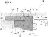
- Fig. 4 is a cross-sectional view showing a constitution of a modified example of an internal combustion engine, not in accordance with the invention.
- the outer circumferential side of the roof surface 31 may be a flat portion 39 having no step.
- the gasket 41B is sandwiched between the outer circumferential side end surface 21p of the cylinder liner 21 and the flat portion 39 of the cylinder head 30B.
- the gasket 41B may extend to the head surface 20f of the cylinder block 20 further on the outer circumferential side than the outer circumferential side end surface 21p.
- the engine 10 may have any constitution.
- the case in which the engine 10 is a gas engine has been described, but the present invention can also be applied to engines using fuels other than gas.
- a stationary type gas engine used for power generation equipment and so on has been described as an embodiment, but it is not limited to the stationary type gas engine.
- the present invention can also be applied to a diffusion combustion type engine.
- the present invention is applied to the premixed combustion type engine, it is advantageous because a greater effect can be obtained with respect to improvement in the fuel economy and achievement of the lower emission than in the diffusion combustion type engine.
- the present invention can be applied to an internal combustion engine with a gap member.
- By applying the present invention to the internal combustion engine with the gap member it is possible to further improve the fuel economy and to achieve low emission of the internal combustion engine and to suppress the breakage of the cylinder liner.
Landscapes
- Engineering & Computer Science (AREA)
- Chemical & Material Sciences (AREA)
- Combustion & Propulsion (AREA)
- Mechanical Engineering (AREA)
- General Engineering & Computer Science (AREA)
- Cylinder Crankcases Of Internal Combustion Engines (AREA)
- Combustion Methods Of Internal-Combustion Engines (AREA)
Claims (2)
- Moteur à combustion interne (10) comprenant :une chemise de cylindre cylindrique (21) dans laquelle un piston (22) se déplace en va-et-vient,un corps de cylindre (20) sur lequel est ajustée la chemise de cylindre (21),une culasse (30A) située pour faire face au corps de cylindre (20) et configurée pour fermer une ouverture (21o) de la chemise de cylindre (21), etune partie d'étanchéité (41A) qui est un matériau en plaque d'acier laminé à froid présentant un module de Young de 205 [GPa], située pour entourer un côté circonférentiel extérieur de l'ouverture (21o) et configurée pour créer une étanchéité entre la culasse (30A) et la chemise de cylindre (21), etun élément d'espacement (60) qui est approprié pour être utilisé dans le moteur à combustion interne (10),dans lequel la chemise de cylindre (21) inclut une surface d'extrémité latérale circonférentielle extérieure (21p) et une surface d'extrémité latérale circonférentielle intérieure (21q) qui sont formées pour être orthogonales à un axe central de la chemise de cylindre (21),dans lequel la surface d'extrémité latérale circonférentielle extérieure (21p) est formée pour inclure une surface d'une partie bride (21f) faisant face à la culasse (30A),dans lequel la surface d'extrémité latérale circonférentielle intérieure (21q) est formée plus près de l'axe central de la chemise de cylindre (21) que la partie bride (21f), et est formée à une position se projetant vers le côté culasse (30A) par rapport à la surface d'extrémité latérale circonférentielle extérieure (21p) via une première partie étagée (21r),dans lequel l'élément d'espacement (60) est disposé dans un espace (S) entre la culasse (30A) et la chemise de cylindre (21) sur un côté circonférentiel intérieur de la partie d'étanchéité (41A),l'élément d'espacement (60) est formé selon une forme de courroie annulaire correspondant à l'espace (S) entre la culasse (30A) et la chemise de cylindre (21), etl'élément d'espacement (60) inclut une partie annulaire (60c) prise en sandwich entre la culasse (30A) et la surface d'extrémité latérale circonférentielle intérieure (21q), et une partie incurvée (60w) formée d'un seul tenant sur un côté circonférentiel extérieur de la partie annulaire (60c) et qui s'étend le long de la première partie étagée (21r) depuis une partie d'extrémité latérale circonférentielle extérieure de la partie annulaire (60c),caractérisé en ce quela culasse (30A) inclut une surface opposée latérale circonférentielle intérieure (31q) et une surface opposée latérale circonférentielle extérieure (31p) qui font face à la surface d'extrémité latérale circonférentielle intérieure (21q) et à la surface d'extrémité latérale circonférentielle extérieure (21p) de la chemise de cylindre (21), respectivement,dans lequel la surface opposée latérale circonférentielle extérieure (31p) est formée à une position faisant saillie vers le côté chemise de cylindre (21) de la surface opposée latérale circonférentielle intérieure (31q),dans lequel la culasse (30A) inclut une seconde partie étagée (31r) entre la surface opposée latérale circonférentielle intérieure (31q) et la surface opposée latérale circonférentielle extérieure (31p),dans lequel l'élément d'espacement (60) est composé de l'un quelconque parmi du polytétrafluoroéthylène et un copolymère de tétrafluoroéthylène/éther vinylique perfluoroalkyle qui est un matériau de résine présentant un module de Young inférieur à celui de la partie d'étanchéité (41A), etla partie d'étanchéité (41A) est disposée loin du côté circonférentiel extérieur de la seconde partie étagée (31r).
- Moteur à combustion interne (10) selon la revendication 1, dans lequel,
dans le moteur à combustion interne (10), un gaz mélangé dans lequel du combustible et de l'air sont mélangés est apporté à une chambre de combustion (33) définie en étant entourée par la chemise de cylindre (21), la culasse (30A) et le piston (22).
Applications Claiming Priority (2)
| Application Number | Priority Date | Filing Date | Title |
|---|---|---|---|
| JP2015207874A JP6655348B2 (ja) | 2015-10-22 | 2015-10-22 | 内燃機関 |
| PCT/JP2016/081111 WO2017069198A1 (fr) | 2015-10-22 | 2016-10-20 | Élément d'espacement et moteur à combustion interne |
Publications (3)
| Publication Number | Publication Date |
|---|---|
| EP3351784A1 EP3351784A1 (fr) | 2018-07-25 |
| EP3351784A4 EP3351784A4 (fr) | 2018-09-05 |
| EP3351784B1 true EP3351784B1 (fr) | 2021-04-14 |
Family
ID=58557076
Family Applications (1)
| Application Number | Title | Priority Date | Filing Date |
|---|---|---|---|
| EP16857511.6A Active EP3351784B1 (fr) | 2015-10-22 | 2016-10-20 | Élément d'espacement et moteur à combustion interne |
Country Status (6)
| Country | Link |
|---|---|
| US (1) | US10619557B2 (fr) |
| EP (1) | EP3351784B1 (fr) |
| JP (1) | JP6655348B2 (fr) |
| KR (1) | KR20180065020A (fr) |
| CN (1) | CN108431393B (fr) |
| WO (1) | WO2017069198A1 (fr) |
Families Citing this family (8)
| Publication number | Priority date | Publication date | Assignee | Title |
|---|---|---|---|---|
| US20190353117A1 (en) * | 2018-05-18 | 2019-11-21 | Caterpillar Inc. | Cylinder liner having a flange with a varied diameter |
| GB2575257B (en) * | 2018-07-02 | 2020-11-04 | Caterpillar Energy Solutions Gmbh | Apparatus for positioning a connecting rod relative to components underlying a cylinder of an engine block |
| JP7656181B2 (ja) * | 2021-04-15 | 2025-04-03 | キョーラク株式会社 | パネル |
| JP7688265B2 (ja) * | 2020-10-15 | 2025-06-04 | キョーラク株式会社 | パネル |
| WO2022080369A1 (fr) * | 2020-10-15 | 2022-04-21 | キョーラク株式会社 | Panneau |
| CN112610348B (zh) * | 2020-12-15 | 2022-11-22 | 重庆隆鑫通航发动机制造有限公司 | 气缸总成及发动机 |
| JP2023107563A (ja) * | 2022-01-24 | 2023-08-03 | 三菱重工エンジン&ターボチャージャ株式会社 | 内燃機関のガスシール構造 |
| US11719182B1 (en) * | 2022-08-17 | 2023-08-08 | Deltahawk Engines, Inc. | Engine cylinder with liner |
Citations (2)
| Publication number | Priority date | Publication date | Assignee | Title |
|---|---|---|---|---|
| DE2227042A1 (de) * | 1972-06-02 | 1973-12-13 | Langen & Co | Dichtungsanordnung |
| US4548165A (en) * | 1983-09-09 | 1985-10-22 | Minsky Motorny Zavod | Internal combustion engine |
Family Cites Families (27)
| Publication number | Priority date | Publication date | Assignee | Title |
|---|---|---|---|---|
| US2939753A (en) | 1957-10-15 | 1960-06-07 | Daimler Benz Ag | Cylinder head gasket arrangement |
| FR1360266A (fr) | 1963-03-26 | 1964-05-08 | Cefilac | Joint pour moteur thermique |
| DE1297405B (de) | 1966-01-11 | 1969-06-12 | Maschf Augsburg Nuernberg Ag | Zylinderdeckeldichtung |
| GB1166370A (en) * | 1966-12-14 | 1969-10-08 | Felt Products Mfg Co | Gaskets. |
| SE338198B (fr) | 1968-12-13 | 1971-08-30 | Crouzet Sa | |
| US3853099A (en) * | 1972-12-21 | 1974-12-10 | Caterpillar Tractor Co | Elastomeric sealing ring for cylinder liners |
| JPS54167204U (fr) * | 1978-05-16 | 1979-11-24 | ||
| US4305348A (en) * | 1978-10-23 | 1981-12-15 | Ramsey Corporation | Seal for an internal combustion engine |
| US4300273A (en) * | 1978-10-26 | 1981-11-17 | Caterpillar Tractor Co. | Method for making laminated spacer plate for engines |
| JPS56113145U (fr) * | 1980-02-01 | 1981-09-01 | ||
| JPS6067751A (ja) * | 1983-09-19 | 1985-04-18 | ミンスキイ モトルニイ ザボツド | 内燃エンジン |
| JPS62152056U (fr) * | 1986-03-20 | 1987-09-26 | ||
| JPS6371456U (fr) * | 1986-10-30 | 1988-05-13 | ||
| JPH0826812B2 (ja) | 1986-11-13 | 1996-03-21 | 日本ラインツ株式会社 | シリンダライナを設けたエンジン用スペ−サ |
| JP2671407B2 (ja) | 1988-07-21 | 1997-10-29 | いすゞ自動車株式会社 | 断熱エンジンの構造 |
| JP2532397Y2 (ja) | 1991-03-26 | 1997-04-16 | いすゞ自動車株式会社 | シリンダライナ |
| JP2000130586A (ja) * | 1998-10-29 | 2000-05-12 | Taiho Kogyo Co Ltd | シリンダヘッドガスケット |
| JP2001193560A (ja) * | 1999-12-28 | 2001-07-17 | Yanmar Diesel Engine Co Ltd | 内燃機関のシリンダヘッドガスケット構造 |
| JP2001280504A (ja) * | 2000-03-31 | 2001-10-10 | Nichias Corp | ゴムガスケット構造およびその製造方法 |
| JP4529321B2 (ja) | 2000-10-13 | 2010-08-25 | Nok株式会社 | インジェクター用燃焼ガスシール |
| US7100925B2 (en) | 2003-07-31 | 2006-09-05 | Perkin Elmer, Inc. | Pressure energized metallic seal |
| JP5167108B2 (ja) | 2008-12-24 | 2013-03-21 | 三菱重工業株式会社 | 点火プラグを備えたガスエンジン |
| JP5123254B2 (ja) * | 2009-05-27 | 2013-01-23 | 株式会社日阪製作所 | バルブ装置 |
| US8601995B2 (en) * | 2011-08-03 | 2013-12-10 | Cummins Intellectual Property, Inc. | Cylinder liner seal arrangement and method of providing the same |
| DE102012013379A1 (de) | 2012-07-04 | 2014-01-09 | Mtu Friedrichshafen Gmbh | Einlage und Verbrennungsmotor mit Einlage |
| CN103293005A (zh) * | 2013-05-31 | 2013-09-11 | 中国兵器工业集团第七0研究所 | 一种点火状态下气缸套与活塞摩擦力测试用浮动缸套机构 |
| US20170226958A1 (en) * | 2016-02-10 | 2017-08-10 | Caterpillar Inc. | Spring Energized Cylinder Liner Seal |
-
2015
- 2015-10-22 JP JP2015207874A patent/JP6655348B2/ja active Active
-
2016
- 2016-10-20 CN CN201680060825.XA patent/CN108431393B/zh active Active
- 2016-10-20 US US15/769,152 patent/US10619557B2/en active Active
- 2016-10-20 KR KR1020187011048A patent/KR20180065020A/ko not_active Ceased
- 2016-10-20 WO PCT/JP2016/081111 patent/WO2017069198A1/fr not_active Ceased
- 2016-10-20 EP EP16857511.6A patent/EP3351784B1/fr active Active
Patent Citations (2)
| Publication number | Priority date | Publication date | Assignee | Title |
|---|---|---|---|---|
| DE2227042A1 (de) * | 1972-06-02 | 1973-12-13 | Langen & Co | Dichtungsanordnung |
| US4548165A (en) * | 1983-09-09 | 1985-10-22 | Minsky Motorny Zavod | Internal combustion engine |
Also Published As
| Publication number | Publication date |
|---|---|
| KR20180065020A (ko) | 2018-06-15 |
| JP6655348B2 (ja) | 2020-02-26 |
| EP3351784A4 (fr) | 2018-09-05 |
| EP3351784A1 (fr) | 2018-07-25 |
| JP2017078392A (ja) | 2017-04-27 |
| WO2017069198A1 (fr) | 2017-04-27 |
| CN108431393B (zh) | 2022-01-11 |
| US20180306099A1 (en) | 2018-10-25 |
| US10619557B2 (en) | 2020-04-14 |
| CN108431393A (zh) | 2018-08-21 |
Similar Documents
| Publication | Publication Date | Title |
|---|---|---|
| EP3351784B1 (fr) | Élément d'espacement et moteur à combustion interne | |
| EP3012431B1 (fr) | Ensemble chambre de précombustion pour moteurs à combustion interne | |
| EP3460929B1 (fr) | Bougie d'allumage pour moteur à combustion interne | |
| EP3118433A1 (fr) | Ensemble chambre de précombustion pour moteurs à combustion interne | |
| JP2015117582A (ja) | ガスエンジン、およびガスエンジンの組立方法 | |
| KR102594227B1 (ko) | 엔진 | |
| US8955487B2 (en) | Piston and cooled piston ring therefor and method of construction thereof | |
| EP3312395B1 (fr) | Joint de queue de soupape dans un moteur à combustion interne | |
| US10323580B2 (en) | Isobaric piston assembly | |
| WO2010075207A1 (fr) | Ensemble piston pourvu d'un passage s'étendant jusqu'à la seconde gorge de segment | |
| US20150069718A1 (en) | Metal gasket assembly | |
| JP2009156395A (ja) | 金属製ガスケット | |
| CN221703851U (zh) | 一种气缸盖及两冲程发动机 | |
| JP2014077365A (ja) | ガスケット | |
| CN219034872U (zh) | 一种燃烧室密封结构及柴油机 | |
| US10519895B2 (en) | Cylinder head and engine | |
| KR101914325B1 (ko) | 엔진 | |
| WO2026039177A1 (fr) | Joint de culasse et chemise de cylindre pour moteur à combustion interne | |
| CN120752427A (zh) | 用于封闭活塞冷却通道的系统和方法 | |
| JP2021134720A (ja) | 内燃機関 | |
| KR20030039004A (ko) | 주철 연소실을 갖는 알루미늄 피스톤 | |
| CN101576019A (zh) | 一种发动机活塞环 | |
| KR19980045537U (ko) | 자동차용 엔진의 피스톤 | |
| JP2013024140A (ja) | 内燃機関 | |
| KR20000042271A (ko) | 자동차의 캠샤프트 커버 체결구조 |
Legal Events
| Date | Code | Title | Description |
|---|---|---|---|
| STAA | Information on the status of an ep patent application or granted ep patent |
Free format text: STATUS: THE INTERNATIONAL PUBLICATION HAS BEEN MADE |
|
| PUAI | Public reference made under article 153(3) epc to a published international application that has entered the european phase |
Free format text: ORIGINAL CODE: 0009012 |
|
| STAA | Information on the status of an ep patent application or granted ep patent |
Free format text: STATUS: REQUEST FOR EXAMINATION WAS MADE |
|
| 17P | Request for examination filed |
Effective date: 20180418 |
|
| AK | Designated contracting states |
Kind code of ref document: A1 Designated state(s): AL AT BE BG CH CY CZ DE DK EE ES FI FR GB GR HR HU IE IS IT LI LT LU LV MC MK MT NL NO PL PT RO RS SE SI SK SM TR |
|
| AX | Request for extension of the european patent |
Extension state: BA ME |
|
| A4 | Supplementary search report drawn up and despatched |
Effective date: 20180808 |
|
| RIC1 | Information provided on ipc code assigned before grant |
Ipc: F02B 23/00 20060101ALI20180802BHEP Ipc: F02F 11/00 20060101AFI20180802BHEP |
|
| DAV | Request for validation of the european patent (deleted) | ||
| DAX | Request for extension of the european patent (deleted) | ||
| STAA | Information on the status of an ep patent application or granted ep patent |
Free format text: STATUS: EXAMINATION IS IN PROGRESS |
|
| 17Q | First examination report despatched |
Effective date: 20190531 |
|
| GRAP | Despatch of communication of intention to grant a patent |
Free format text: ORIGINAL CODE: EPIDOSNIGR1 |
|
| STAA | Information on the status of an ep patent application or granted ep patent |
Free format text: STATUS: GRANT OF PATENT IS INTENDED |
|
| INTG | Intention to grant announced |
Effective date: 20201210 |
|
| GRAS | Grant fee paid |
Free format text: ORIGINAL CODE: EPIDOSNIGR3 |
|
| GRAA | (expected) grant |
Free format text: ORIGINAL CODE: 0009210 |
|
| STAA | Information on the status of an ep patent application or granted ep patent |
Free format text: STATUS: THE PATENT HAS BEEN GRANTED |
|
| AK | Designated contracting states |
Kind code of ref document: B1 Designated state(s): AL AT BE BG CH CY CZ DE DK EE ES FI FR GB GR HR HU IE IS IT LI LT LU LV MC MK MT NL NO PL PT RO RS SE SI SK SM TR |
|
| REG | Reference to a national code |
Ref country code: GB Ref legal event code: FG4D |
|
| REG | Reference to a national code |
Ref country code: CH Ref legal event code: EP |
|
| REG | Reference to a national code |
Ref country code: DE Ref legal event code: R096 Ref document number: 602016056242 Country of ref document: DE |
|
| REG | Reference to a national code |
Ref country code: IE Ref legal event code: FG4D |
|
| REG | Reference to a national code |
Ref country code: FI Ref legal event code: FGE |
|
| REG | Reference to a national code |
Ref country code: AT Ref legal event code: REF Ref document number: 1382593 Country of ref document: AT Kind code of ref document: T Effective date: 20210515 |
|
| REG | Reference to a national code |
Ref country code: NO Ref legal event code: T2 Effective date: 20210414 |
|
| REG | Reference to a national code |
Ref country code: LT Ref legal event code: MG9D |
|
| REG | Reference to a national code |
Ref country code: NL Ref legal event code: MP Effective date: 20210414 |
|
| PG25 | Lapsed in a contracting state [announced via postgrant information from national office to epo] |
Ref country code: BG Free format text: LAPSE BECAUSE OF FAILURE TO SUBMIT A TRANSLATION OF THE DESCRIPTION OR TO PAY THE FEE WITHIN THE PRESCRIBED TIME-LIMIT Effective date: 20210714 Ref country code: HR Free format text: LAPSE BECAUSE OF FAILURE TO SUBMIT A TRANSLATION OF THE DESCRIPTION OR TO PAY THE FEE WITHIN THE PRESCRIBED TIME-LIMIT Effective date: 20210414 Ref country code: NL Free format text: LAPSE BECAUSE OF FAILURE TO SUBMIT A TRANSLATION OF THE DESCRIPTION OR TO PAY THE FEE WITHIN THE PRESCRIBED TIME-LIMIT Effective date: 20210414 Ref country code: LT Free format text: LAPSE BECAUSE OF FAILURE TO SUBMIT A TRANSLATION OF THE DESCRIPTION OR TO PAY THE FEE WITHIN THE PRESCRIBED TIME-LIMIT Effective date: 20210414 |
|
| PG25 | Lapsed in a contracting state [announced via postgrant information from national office to epo] |
Ref country code: IS Free format text: LAPSE BECAUSE OF FAILURE TO SUBMIT A TRANSLATION OF THE DESCRIPTION OR TO PAY THE FEE WITHIN THE PRESCRIBED TIME-LIMIT Effective date: 20210814 Ref country code: LV Free format text: LAPSE BECAUSE OF FAILURE TO SUBMIT A TRANSLATION OF THE DESCRIPTION OR TO PAY THE FEE WITHIN THE PRESCRIBED TIME-LIMIT Effective date: 20210414 Ref country code: GR Free format text: LAPSE BECAUSE OF FAILURE TO SUBMIT A TRANSLATION OF THE DESCRIPTION OR TO PAY THE FEE WITHIN THE PRESCRIBED TIME-LIMIT Effective date: 20210715 Ref country code: PL Free format text: LAPSE BECAUSE OF FAILURE TO SUBMIT A TRANSLATION OF THE DESCRIPTION OR TO PAY THE FEE WITHIN THE PRESCRIBED TIME-LIMIT Effective date: 20210414 Ref country code: PT Free format text: LAPSE BECAUSE OF FAILURE TO SUBMIT A TRANSLATION OF THE DESCRIPTION OR TO PAY THE FEE WITHIN THE PRESCRIBED TIME-LIMIT Effective date: 20210816 Ref country code: SE Free format text: LAPSE BECAUSE OF FAILURE TO SUBMIT A TRANSLATION OF THE DESCRIPTION OR TO PAY THE FEE WITHIN THE PRESCRIBED TIME-LIMIT Effective date: 20210414 Ref country code: RS Free format text: LAPSE BECAUSE OF FAILURE TO SUBMIT A TRANSLATION OF THE DESCRIPTION OR TO PAY THE FEE WITHIN THE PRESCRIBED TIME-LIMIT Effective date: 20210414 |
|
| REG | Reference to a national code |
Ref country code: DE Ref legal event code: R097 Ref document number: 602016056242 Country of ref document: DE |
|
| PG25 | Lapsed in a contracting state [announced via postgrant information from national office to epo] |
Ref country code: ES Free format text: LAPSE BECAUSE OF FAILURE TO SUBMIT A TRANSLATION OF THE DESCRIPTION OR TO PAY THE FEE WITHIN THE PRESCRIBED TIME-LIMIT Effective date: 20210414 Ref country code: RO Free format text: LAPSE BECAUSE OF FAILURE TO SUBMIT A TRANSLATION OF THE DESCRIPTION OR TO PAY THE FEE WITHIN THE PRESCRIBED TIME-LIMIT Effective date: 20210414 Ref country code: CZ Free format text: LAPSE BECAUSE OF FAILURE TO SUBMIT A TRANSLATION OF THE DESCRIPTION OR TO PAY THE FEE WITHIN THE PRESCRIBED TIME-LIMIT Effective date: 20210414 Ref country code: DK Free format text: LAPSE BECAUSE OF FAILURE TO SUBMIT A TRANSLATION OF THE DESCRIPTION OR TO PAY THE FEE WITHIN THE PRESCRIBED TIME-LIMIT Effective date: 20210414 Ref country code: EE Free format text: LAPSE BECAUSE OF FAILURE TO SUBMIT A TRANSLATION OF THE DESCRIPTION OR TO PAY THE FEE WITHIN THE PRESCRIBED TIME-LIMIT Effective date: 20210414 Ref country code: SK Free format text: LAPSE BECAUSE OF FAILURE TO SUBMIT A TRANSLATION OF THE DESCRIPTION OR TO PAY THE FEE WITHIN THE PRESCRIBED TIME-LIMIT Effective date: 20210414 Ref country code: SM Free format text: LAPSE BECAUSE OF FAILURE TO SUBMIT A TRANSLATION OF THE DESCRIPTION OR TO PAY THE FEE WITHIN THE PRESCRIBED TIME-LIMIT Effective date: 20210414 |
|
| PLBE | No opposition filed within time limit |
Free format text: ORIGINAL CODE: 0009261 |
|
| STAA | Information on the status of an ep patent application or granted ep patent |
Free format text: STATUS: NO OPPOSITION FILED WITHIN TIME LIMIT |
|
| 26N | No opposition filed |
Effective date: 20220117 |
|
| REG | Reference to a national code |
Ref country code: CH Ref legal event code: PL |
|
| PG25 | Lapsed in a contracting state [announced via postgrant information from national office to epo] |
Ref country code: IS Free format text: LAPSE BECAUSE OF FAILURE TO SUBMIT A TRANSLATION OF THE DESCRIPTION OR TO PAY THE FEE WITHIN THE PRESCRIBED TIME-LIMIT Effective date: 20210814 Ref country code: AL Free format text: LAPSE BECAUSE OF FAILURE TO SUBMIT A TRANSLATION OF THE DESCRIPTION OR TO PAY THE FEE WITHIN THE PRESCRIBED TIME-LIMIT Effective date: 20210414 |
|
| REG | Reference to a national code |
Ref country code: BE Ref legal event code: MM Effective date: 20211031 |
|
| PG25 | Lapsed in a contracting state [announced via postgrant information from national office to epo] |
Ref country code: MC Free format text: LAPSE BECAUSE OF FAILURE TO SUBMIT A TRANSLATION OF THE DESCRIPTION OR TO PAY THE FEE WITHIN THE PRESCRIBED TIME-LIMIT Effective date: 20210414 |
|
| PG25 | Lapsed in a contracting state [announced via postgrant information from national office to epo] |
Ref country code: LU Free format text: LAPSE BECAUSE OF NON-PAYMENT OF DUE FEES Effective date: 20211020 Ref country code: IT Free format text: LAPSE BECAUSE OF FAILURE TO SUBMIT A TRANSLATION OF THE DESCRIPTION OR TO PAY THE FEE WITHIN THE PRESCRIBED TIME-LIMIT Effective date: 20210414 Ref country code: BE Free format text: LAPSE BECAUSE OF NON-PAYMENT OF DUE FEES Effective date: 20211031 |
|
| PG25 | Lapsed in a contracting state [announced via postgrant information from national office to epo] |
Ref country code: LI Free format text: LAPSE BECAUSE OF NON-PAYMENT OF DUE FEES Effective date: 20211031 Ref country code: CH Free format text: LAPSE BECAUSE OF NON-PAYMENT OF DUE FEES Effective date: 20211031 |
|
| PG25 | Lapsed in a contracting state [announced via postgrant information from national office to epo] |
Ref country code: FR Free format text: LAPSE BECAUSE OF NON-PAYMENT OF DUE FEES Effective date: 20211031 |
|
| PG25 | Lapsed in a contracting state [announced via postgrant information from national office to epo] |
Ref country code: IE Free format text: LAPSE BECAUSE OF NON-PAYMENT OF DUE FEES Effective date: 20211020 |
|
| REG | Reference to a national code |
Ref country code: AT Ref legal event code: UEP Ref document number: 1382593 Country of ref document: AT Kind code of ref document: T Effective date: 20210414 |
|
| PG25 | Lapsed in a contracting state [announced via postgrant information from national office to epo] |
Ref country code: HU Free format text: LAPSE BECAUSE OF FAILURE TO SUBMIT A TRANSLATION OF THE DESCRIPTION OR TO PAY THE FEE WITHIN THE PRESCRIBED TIME-LIMIT; INVALID AB INITIO Effective date: 20161020 |
|
| PG25 | Lapsed in a contracting state [announced via postgrant information from national office to epo] |
Ref country code: CY Free format text: LAPSE BECAUSE OF FAILURE TO SUBMIT A TRANSLATION OF THE DESCRIPTION OR TO PAY THE FEE WITHIN THE PRESCRIBED TIME-LIMIT Effective date: 20210414 |
|
| PG25 | Lapsed in a contracting state [announced via postgrant information from national office to epo] |
Ref country code: MK Free format text: LAPSE BECAUSE OF FAILURE TO SUBMIT A TRANSLATION OF THE DESCRIPTION OR TO PAY THE FEE WITHIN THE PRESCRIBED TIME-LIMIT Effective date: 20210414 |
|
| PG25 | Lapsed in a contracting state [announced via postgrant information from national office to epo] |
Ref country code: MT Free format text: LAPSE BECAUSE OF FAILURE TO SUBMIT A TRANSLATION OF THE DESCRIPTION OR TO PAY THE FEE WITHIN THE PRESCRIBED TIME-LIMIT Effective date: 20210414 |
|
| PGFP | Annual fee paid to national office [announced via postgrant information from national office to epo] |
Ref country code: GB Payment date: 20250828 Year of fee payment: 10 |
|
| PG25 | Lapsed in a contracting state [announced via postgrant information from national office to epo] |
Ref country code: TR Free format text: LAPSE BECAUSE OF FAILURE TO SUBMIT A TRANSLATION OF THE DESCRIPTION OR TO PAY THE FEE WITHIN THE PRESCRIBED TIME-LIMIT Effective date: 20210414 |
|
| PGFP | Annual fee paid to national office [announced via postgrant information from national office to epo] |
Ref country code: DE Payment date: 20250902 Year of fee payment: 10 |
|
| PGFP | Annual fee paid to national office [announced via postgrant information from national office to epo] |
Ref country code: NO Payment date: 20251009 Year of fee payment: 10 |
|
| PGFP | Annual fee paid to national office [announced via postgrant information from national office to epo] |
Ref country code: AT Payment date: 20250925 Year of fee payment: 10 |
|
| PGFP | Annual fee paid to national office [announced via postgrant information from national office to epo] |
Ref country code: FI Payment date: 20251014 Year of fee payment: 10 |