EP3351838A1 - Microphone optique destiné au diagnostic d' appareils de réglage - Google Patents
Microphone optique destiné au diagnostic d' appareils de réglage Download PDFInfo
- Publication number
- EP3351838A1 EP3351838A1 EP18151759.0A EP18151759A EP3351838A1 EP 3351838 A1 EP3351838 A1 EP 3351838A1 EP 18151759 A EP18151759 A EP 18151759A EP 3351838 A1 EP3351838 A1 EP 3351838A1
- Authority
- EP
- European Patent Office
- Prior art keywords
- actuator
- optical microphone
- sound
- acoustic
- plant
- Prior art date
- Legal status (The legal status is an assumption and is not a legal conclusion. Google has not performed a legal analysis and makes no representation as to the accuracy of the status listed.)
- Granted
Links
Images
Classifications
-
- F—MECHANICAL ENGINEERING; LIGHTING; HEATING; WEAPONS; BLASTING
- F16—ENGINEERING ELEMENTS AND UNITS; GENERAL MEASURES FOR PRODUCING AND MAINTAINING EFFECTIVE FUNCTIONING OF MACHINES OR INSTALLATIONS; THERMAL INSULATION IN GENERAL
- F16K—VALVES; TAPS; COCKS; ACTUATING-FLOATS; DEVICES FOR VENTING OR AERATING
- F16K37/00—Special means in or on valves or other cut-off apparatus for indicating or recording operation thereof, or for enabling an alarm to be given
- F16K37/0075—For recording or indicating the functioning of a valve in combination with test equipment
- F16K37/0083—For recording or indicating the functioning of a valve in combination with test equipment by measuring valve parameters
-
- F—MECHANICAL ENGINEERING; LIGHTING; HEATING; WEAPONS; BLASTING
- F16—ENGINEERING ELEMENTS AND UNITS; GENERAL MEASURES FOR PRODUCING AND MAINTAINING EFFECTIVE FUNCTIONING OF MACHINES OR INSTALLATIONS; THERMAL INSULATION IN GENERAL
- F16K—VALVES; TAPS; COCKS; ACTUATING-FLOATS; DEVICES FOR VENTING OR AERATING
- F16K37/00—Special means in or on valves or other cut-off apparatus for indicating or recording operation thereof, or for enabling an alarm to be given
- F16K37/0025—Electrical or magnetic means
- F16K37/0041—Electrical or magnetic means for measuring valve parameters
-
- F—MECHANICAL ENGINEERING; LIGHTING; HEATING; WEAPONS; BLASTING
- F16—ENGINEERING ELEMENTS AND UNITS; GENERAL MEASURES FOR PRODUCING AND MAINTAINING EFFECTIVE FUNCTIONING OF MACHINES OR INSTALLATIONS; THERMAL INSULATION IN GENERAL
- F16K—VALVES; TAPS; COCKS; ACTUATING-FLOATS; DEVICES FOR VENTING OR AERATING
- F16K37/00—Special means in or on valves or other cut-off apparatus for indicating or recording operation thereof, or for enabling an alarm to be given
- F16K37/0025—Electrical or magnetic means
- F16K37/005—Electrical or magnetic means for measuring fluid parameters
-
- F—MECHANICAL ENGINEERING; LIGHTING; HEATING; WEAPONS; BLASTING
- F16—ENGINEERING ELEMENTS AND UNITS; GENERAL MEASURES FOR PRODUCING AND MAINTAINING EFFECTIVE FUNCTIONING OF MACHINES OR INSTALLATIONS; THERMAL INSULATION IN GENERAL
- F16K—VALVES; TAPS; COCKS; ACTUATING-FLOATS; DEVICES FOR VENTING OR AERATING
- F16K37/00—Special means in or on valves or other cut-off apparatus for indicating or recording operation thereof, or for enabling an alarm to be given
- F16K37/0058—Optical means, e.g. light transmission, observation ports
-
- G—PHYSICS
- G01—MEASURING; TESTING
- G01H—MEASUREMENT OF MECHANICAL VIBRATIONS OR ULTRASONIC, SONIC OR INFRASONIC WAVES
- G01H9/00—Measuring mechanical vibrations or ultrasonic, sonic or infrasonic waves by using radiation-sensitive means, e.g. optical means
-
- G—PHYSICS
- G01—MEASURING; TESTING
- G01M—TESTING STATIC OR DYNAMIC BALANCE OF MACHINES OR STRUCTURES; TESTING OF STRUCTURES OR APPARATUS, NOT OTHERWISE PROVIDED FOR
- G01M3/00—Investigating fluid-tightness of structures
- G01M3/02—Investigating fluid-tightness of structures by using fluid or vacuum
- G01M3/025—Details with respect to the testing of engines or engine parts
-
- G—PHYSICS
- G01—MEASURING; TESTING
- G01M—TESTING STATIC OR DYNAMIC BALANCE OF MACHINES OR STRUCTURES; TESTING OF STRUCTURES OR APPARATUS, NOT OTHERWISE PROVIDED FOR
- G01M3/00—Investigating fluid-tightness of structures
- G01M3/02—Investigating fluid-tightness of structures by using fluid or vacuum
- G01M3/04—Investigating fluid-tightness of structures by using fluid or vacuum by detecting the presence of fluid at the leakage point
- G01M3/24—Investigating fluid-tightness of structures by using fluid or vacuum by detecting the presence of fluid at the leakage point using infrasonic, sonic or ultrasonic vibrations
-
- G—PHYSICS
- G01—MEASURING; TESTING
- G01M—TESTING STATIC OR DYNAMIC BALANCE OF MACHINES OR STRUCTURES; TESTING OF STRUCTURES OR APPARATUS, NOT OTHERWISE PROVIDED FOR
- G01M3/00—Investigating fluid-tightness of structures
- G01M3/38—Investigating fluid-tightness of structures by using light
-
- G—PHYSICS
- G01—MEASURING; TESTING
- G01N—INVESTIGATING OR ANALYSING MATERIALS BY DETERMINING THEIR CHEMICAL OR PHYSICAL PROPERTIES
- G01N29/00—Investigating or analysing materials by the use of ultrasonic, sonic or infrasonic waves; Visualisation of the interior of objects by transmitting ultrasonic or sonic waves through the object
- G01N29/02—Analysing fluids
- G01N29/036—Analysing fluids by measuring frequency or resonance of acoustic waves
-
- H—ELECTRICITY
- H04—ELECTRIC COMMUNICATION TECHNIQUE
- H04R—LOUDSPEAKERS, MICROPHONES, GRAMOPHONE PICK-UPS OR LIKE ACOUSTIC ELECTROMECHANICAL TRANSDUCERS; ELECTRIC HEARING AIDS; PUBLIC ADDRESS SYSTEMS
- H04R1/00—Details of transducers, loudspeakers or microphones
- H04R1/02—Casings; Cabinets ; Supports therefor; Mountings therein
- H04R1/028—Casings; Cabinets ; Supports therefor; Mountings therein associated with devices performing functions other than acoustics, e.g. electric candles
-
- H—ELECTRICITY
- H04—ELECTRIC COMMUNICATION TECHNIQUE
- H04R—LOUDSPEAKERS, MICROPHONES, GRAMOPHONE PICK-UPS OR LIKE ACOUSTIC ELECTROMECHANICAL TRANSDUCERS; ELECTRIC HEARING AIDS; PUBLIC ADDRESS SYSTEMS
- H04R23/00—Transducers other than those covered by groups H04R9/00 - H04R21/00
- H04R23/008—Transducers other than those covered by groups H04R9/00 - H04R21/00 using optical signals for detecting or generating sound
-
- H—ELECTRICITY
- H04—ELECTRIC COMMUNICATION TECHNIQUE
- H04R—LOUDSPEAKERS, MICROPHONES, GRAMOPHONE PICK-UPS OR LIKE ACOUSTIC ELECTROMECHANICAL TRANSDUCERS; ELECTRIC HEARING AIDS; PUBLIC ADDRESS SYSTEMS
- H04R29/00—Monitoring arrangements; Testing arrangements
- H04R29/004—Monitoring arrangements; Testing arrangements for microphones
-
- E—FIXED CONSTRUCTIONS
- E21—EARTH OR ROCK DRILLING; MINING
- E21B—EARTH OR ROCK DRILLING; OBTAINING OIL, GAS, WATER, SOLUBLE OR MELTABLE MATERIALS OR A SLURRY OF MINERALS FROM WELLS
- E21B47/00—Survey of boreholes or wells
- E21B47/10—Locating fluid leaks, intrusions or movements
- E21B47/107—Locating fluid leaks, intrusions or movements using acoustic means
Definitions
- the invention relates to a diagnostic system for controlling the operability of a control device of a process plant, such as a chemical plant, a food processing plant, a power plant or the like.
- An actuating device has, for example, at least one control valve, such as an emergency shut-off valve or a control valve, via which a medium flow, in particular a fluid flow, of the process-technical system can be controlled and adjusted.
- the actuator can also be operated with auxiliary power, such as pneumatics, in particular, the actuator can be operated via a particular electropneumatic positioner.
- the invention relates to the actuating device as such, which comprises the diagnostic system according to the invention.
- the invention relates to a field device of a process plant, with which the process fluid flow can be controlled.
- the field device is an integrated into the process plant conditioning device, which includes, for example, in addition to a control valve, an actuator and optionally an actuator controlling the electronic unit, whereby for example a pump may be connected in combination.
- the process fluid flow can be a process fluid flow that is subject to explosion protection during processing in large plants.
- the diagnostic system according to the invention is intended in particular to meet the requirements of safety technology for the prevention of explosions, ignition protection types being defined according to standards such as IEC, EN, ATEX or NEC.
- Actuators such as control valves, which influence the process medium flow of the process plant, in particular control and / or regulate, can assume critical operating conditions.
- these are, for example, leakage or cavitation, which are accompanied by a characteristic acoustic emission. It is known to record and evaluate the acoustic emissions of the actuator acoustically. An early detection of actuator damage is to be achieved in order to avoid a complete failure of the actuator or an interruption to avoid the plant operation, for example, due to acute maintenance and repair work on the process plant.
- a diagnostic system for regulating and shut-off valves of a process plant is, for example EP 0 637 713 A1 known.
- the diagnostic system uses an electronic processor of a positioner, which is connected to a structure-borne sound sensor, which listens to a valve head and generates measurement data for determining cavitation. In the event of an impermissible deviation of the measured sound values from comparison measured values previously recorded during correct operation of the control valve, an alarm signal is output. Due to the direct arrangement of the structure-borne sound sensor on the upper valve part, the diagnostic system is susceptible to false alarms, because the origin of the sound is identifiable only with an increased diagnostic effort.
- a diagnostic system for a positioner of a control valve of a process plant is also off DE 199 24 377 B4 known, wherein a structure-borne sound sensor is mounted directly on the outside of the control valve housing. It is recorded a structure-borne noise spectrum at slightly open control valve and compared in operation with the valve closed. After comparing both measured values, a conclusion can be drawn about the tightness or leakage of the control valve. Even with this diagnostic system is not to assume a high reliability.
- WO 02/077733 A1 a diagnostic device for a field device in the industrial environment of a process plant known.
- the field device is connected via a data path to a central controller and comprises an acoustic data acquisition device in the form of a microphone.
- This diagnostic device has the disadvantage of low measurement accuracy.
- DE 10 2006 055 747 A1 discloses a diagnostic system for a control valve operated by a pneumatic actuator controlled by a positioner. To check the correct functioning of the control valve, it is known that specific acoustic signals are emitted during normal use. These should be included in the pneumatic actuator, from which conclusions about the state of the control valve should be closed. It is based on the knowledge that acoustic signals are transmitted to the diaphragm of the pneumatic actuator, which acoustic signals are amplified by the large diaphragm and passed to the air pressure medium. The acoustic sensor used is a pressure sensor. The diagnostic system also suffers from low reliability and high diagnostic effort to filter out the significant signals from the nonessential signals for the assessment of the operability of the control valve.
- a positioner controls the pneumatic auxiliary power supplied to the actuator.
- the positioner has a nozzle flapper arrangement, which is also used as a sensor.
- Such a diagnostic system is temperature-dependent and therefore rather unsuitable for use in the process engineering plant.
- EP 2 191 182 B1 teaches a structure-borne sound pick-up, which is integrated in a fastening screw that attaches the positioner to the field device.
- the pressure of the process fluid at the inlet side is measured and compared with a reference pressure.
- the diagnostic system triggers an alarm when the measured Structure-borne sound level exceeds a reference value and at the same time a pressure reading is less than the reference pressure value. Precise statements about leakage or cavitation can not be achieved with the known system.
- a diagnostic system for controlling the operability of a control device such as a control valve, which serves to influence a process fluid flow of a process plant, such as a chemical plant, a food processing plant, a power plant or the like.
- the actuator should be designed to set a potentially explosive process fluid flow.
- the diagnostic system as well as the actuator are suitable to be used in the EX area.
- pneumatic is preferably used as an auxiliary drive energy to avoid high electrical voltages and current flows. Only for diagnosis and sensor technology is it possible to use a small amount of electrical power, in particular of a few watts.
- the diagnostic system has an optical microphone, which is in particular aligned to a structural element, such as an inner organ or the outside of the actuator and an acoustic, actuator-specific operating signal or operating noise, such as leakage sound, cavitation, by means of electromagnetic radiation, such as light, measures by the acoustic, actuator-specific operating signal is influenced.
- the optical microphone uses the resulting due to sound, namely sound pressure waves, changes in the electromagnetic radiation at a microphone-specific alignment point.
- the optical microphone can generate an electrical measurement signal that depends on the acoustic operating signal.
- the diagnostic system has an electronic diagnostic device which receives the electrical measurement signal of the optical microphone and in particular subsequently stores, processes and / or forwards, in particular to an actuator-specific electronic unit, such as a microcomputer, for example a positioner, or to a control room connected to the control device of the process plant.
- an actuator-specific electronic unit such as a microcomputer, for example a positioner, or to a control room connected to the control device of the process plant.
- the diagnostic system uses an optical microphone which either uses existing electromagnetic radiation, in particular its visible part (380 nm to 780 nm, ambient light) or has an artificial, micro-own light source, which can be realized, for example, as a laser diode.
- the light source preferably cooperates with a measuring head, which may be designed, for example, as an interferometric mirror.
- the measuring head may be movably mounted relative to the light source, wherein the light source may be movably mounted.
- both light sources are arranged stationary relative to one another.
- the measuring head and the light source of the optical microphone are preferably flexibly coupled to each other via a particularly deformable optical waveguide, so that a relative movement between the measuring head and the light source is permitted without the optical waveguide between measuring head and light source being impaired.
- a sensitive laser diode it may be arranged in a protected area, for example in a housing, separate from the measuring head and / or the alignment point in order not to be exposed to harsh environmental conditions on or in the actuator.
- the sound pressure generated by the acoustic, actuator-specific operating signal in particular its change, can be detected optically via the change in the refractive index in the air, which is caused by sound waves.
- the acoustic, actuator-specific operating signals are typical operating noise emitted by the actuator at certain points of the actuator with higher intensity. These points of higher noise intensity are often difficult to access, but can be scanned with the optical microphone according to the invention.
- the leakage sound or cavitation sound can be recorded in particular in the vicinity of the closing member of the control valve with high intensity, which requires an arrangement of the transducer in the process medium, which can just be achieved by an optical microphone.
- reference values such as empirical values
- a leakage sound for example, can be recorded by the actuator specifically that the intact actuator according to a conventional leakage wear passage opens, which sets typical flow noise, which are stored device-specific.
- the most precise possible conversion of the acoustic operating signal or operating noise into electrical measuring signals is achieved by the optical microphone, which detects either the variability of the ambient light due to the sound pressure fluctuations or detects the change in the speed of light of a light beam of a microphone-own light source, such as a laser beam passing through the sound field becomes.
- the change in the speed of light is proportional to the sound pressure.
- an interference arrangement can be used by comparing changes in the speed of light in a sound-free air field with those of the sound field interspersed with the operating noise.
- the optical microphone can have, for example, two laser beam sources which travel the same distance, wherein the one beam traversing field is unaffected by the acoustic, actuator-specific operating signal, while the sound field is penetrated by it.
- a detector is provided which outputs the measured interference as an electrical measurement signal.
- the optical microphone has a first interferometer and a second interferometer, each capable of receiving light from one and the same light source.
- a very meaningful spatial resolution of the sound field is achieved.
- Each interferometer can have a beam splitter for itself, which sends the light or laser beam in two different, but equally long ways. One partial beam is exposed to the sound field, the other is acoustically isolated. Both sub-beams are, after they have been reflected many times in mirrors, again brought together and interfere with each other.
- the respective interferometer may be a Fabry-Perot interferometer.
- the diagnostic system according to the invention increased reliability in the early detection of wear damage, in particular leakage and cavitation, can be achieved in the field of the procedural use of actuating devices, in particular control valves, in process engineering systems. It has been found that the non-contact measurement of acoustic operating noise, which are specific to certain operating states of the actuator, can be detected precisely without structural contact. Surprisingly, it also became apparent that the use of an optical microphone, the sound waves on the change The refractive index of a permeated with sound waves gas medium, such as air, detected, achieved particularly accurate measurements for higher frequencies, which are important especially in the determination of cavitation and precise leakage quantities.
- the diagnostic system according to the invention is particularly advantageous due to the possibility of building it robust and compact.
- Gaseous media are generally suitable in which the speed of light changes due to sound pressure waves in the medium.
- the optical microphone can comprise a corresponding transducer which comprises one or more interferometers, in particular with a stationary, in particular movable mirror.
- one or more radiation detectors may be provided, which are designed to detect the electromagnetic radiation influenced by the sound waves and to convert the detected, influenced electromagnetic radiation into the magnetic measurement signal.
- the electronic diagnostic device of the diagnostic system receives the electrical measurement signal.
- the electronic diagnostic device is designed as a memory, such as ROM or RAM, and / or microcomputer.
- the diagnostic device may store the electrical measurement signal, the memory in particular need not be designed to be constantly supplied with electrical energy to obtain the stored signal.
- the diagnostic device can also be designed to evaluate the electrical measurement signal, in particular with regard to a reference value. Will the reference value exceeded, the electronic diagnostic unit may be configured to output an alarm signal, acoustically or visually.
- the diagnostic device can influence the control of a positioner of the actuating device on the basis of the electrical measuring signals.
- the diagnostic device should be designed to forward the electrical measurement signal to a further electronic component, such as the positioner, a control room of the actuator, a transmitting device, a display device of the actuator, etc.
- the optical microphone is designed without a diaphragm and therefore requires no moving components, whereby an extremely precise identification of the acoustic, actuator-specific operating signal is achieved.
- the optical microphone is designed to detect sound pressure optically via the detection of the change in the refractive index of the air in the course of the sound waves of the acoustic, actuator-specific operating signal.
- the optical microphone is arranged inside a housing of the actuating device, such as the valve housing of the control valve, wherein the interior of the housing is flowed through by process medium, wherein in particular the optical microphone to a valve closure member, a valve seat and / or a Valve rod of the control valve is aligned.
- a particular further optical microphone may be arranged in a process-medium-carrying pipeline of the process-technical plant, in particular adjacent to the actuating device, wherein in particular the optical microphone is aligned in the interior of the housing of the actuating device.
- the optical microphone may be arranged in a pneumatic line of a pneumatic actuator system of the actuator, wherein in particular the optical microphone can be aligned with a solenoid valve, in particular a positioner of the actuator.
- the optical microphone can be arranged in a pneumatic working chamber of a pneumatic actuator of the actuator, wherein in particular the optical microphone can be aligned with a membrane or a bellows of the actuator, the / separates two working chambers of the actuator from each other.
- the optical microphone may also be arranged outside the actuating device, in particular the actuator housing, for example on the yoke or lantern connecting the control valve to an actuator, a connecting flange of an actuator and the control valve, for example a housing of the actuator, on the drive rod of the actuator Actuator itself, near the positioner.
- the optical microphone may be arranged on a flow divider to which specific operating noise is to be expected.
- a further alternative or additional positioning of an optical microphone can be realized on the connecting bolt, which acts, for example, as a sound bridge between the valve housing and the yoke.
- a particularly suitable use according to the invention of the optical microphone is achieved in that the optical microphone is arranged in the flow of the process fluid itself.
- the optical microphone is formed by an arrangement of at least two, preferably exactly two or three, optical microphone units, wherein the microphone units can be designed according to the structure shown above.
- Each microphone unit has the ability to generate soundwave-specific electrical measurement signals.
- the arrangement is carried out in such a way, in particular, the at least two microphone units are positioned relative to one another in such a way that a sound field of the acoustic, actuator-specific operating signal can be multidimensionally resolved by means of the measuring signals respectively generated by the microphone unit.
- the arrangement of at least two microphone units can, for example, be coupled to the diagnostic device in signal transmission manner, which process, store and / or forward the at least two measurement signals.
- the diagnostic device is designed to perform a three-dimensional resolution of the sound field based on the transmitted measurement signals of three optical microphones.
- the diagnostic device can perform the evaluation of the measurement signals of the arrangement in such a way that it locates the sound source, in particular the leakage or the cavitation, and / or determines the speed of sound.
- a multidimensional resolution of the sound field can also be achieved by using only one microphone unit, but this, at least a part of it, is movable with respect to the sound field to be detected, in order to adopt several "perspectives" for the optical detection of the sound field.
- it is preferably not necessary to use a plurality of optical microphones, but it can also with a single laser diode whose light is coupled into a plurality of optical fibers, several measuring heads (interferometric mirror) are supplied.
- the diagnostic system comprises an adjusting or displacing device for moving at least part of the optical microphone, such as its measuring head, for example an interferometric mirror or light source, opposite a spatially defined sound field on the actuator.
- the displacement path is predefined, in particular defined translationally.
- the adjusting device comprises a particular electric drive, which can move the at least a part of the optical microphone.
- the drive can, for example, comprise piezoelectric material and / or is supplied with, in particular, electrical energy, which is taken from the process medium flow or an auxiliary energy source, such as a pneumatic pressure source.
- the energy taken from the environment, the process medium and / or the auxiliary energy can not only be used to operate the adjusting device, but can also be used after conversion into electrical energy by means of a suitably dimensioned generator for operating the light source, such as a laser diode.
- a suitably dimensioned generator for operating the light source such as a laser diode.
- the optical microphone with a laser diode and a measuring head, the latter can be movably mounted, wherein the drive of the adjusting device moves the measuring head relative to the laser diode.
- the measuring head should not only be moved back and forth from a sound field or a measuring surface, but also be scanned back and forth across it.
- the diagnostic system additionally comprises a piezoelectric structure-borne sound sensor or a sound sensor with a membrane receiving the sound waves, wherein the measurement data of the structure-borne sound sensor or the sound sensor is passed to the diagnostic device, in particular to evaluate the processing of the measurement signal generated by the optical microphone.
- the precision of the detection of acoustic operating signals of the actuator can be increased.
- the optical microphone comprises a light source, such as a laser diode, and a measuring head, which are coupled to each other via a particular flexible optical waveguide, such as a fiber optic cable, that the light source and the measuring head can be kept movable to each other
- the measuring head has at least one light divider to produce a first light beam exposed to the sound waves of the acoustic operating signal and a second light beam at least partially following a path protected by the sound waves.
- the invention relates to a diagnostic method or a method for controlling the functionality of the actuating device, such as the control valve, which influences a process medium flow of a process plant, such as a chemical plant, a food processing plant, a power plant or the like.
- an acoustic, actuator-specific operating signal such as operating noise, for example leakage sound, cavitation noise, is measured by means of the acoustic, actuator-specific operating signal influenced, electromagnetic radiation.
- a dependent of the acoustic, actuator-specific operating signal, electrical measurement signal is generated to pass it in particular to the diagnostic device.
- the measurement signal is compared, in particular, with a reference variable or a setpoint value in order to judge the functioning of the actuator and / or its components.
- the invention relates to a field device or actuating device, such as a control valve, for influencing the process medium flow of the process plant.
- actuating device comprises a diagnostic system according to the invention, and preferably the actuating device is additionally combined with a pneumatic actuator which is intended to actuate the actuating device.
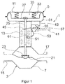
- Fig. 1 the actuator according to the invention is shown with a diagnostic system according to the invention.
- the actuator is in the special version according to Fig. 1 as a complete Field device extended by the reference numeral 1, which comprises a control valve 3 and a pneumatic actuator 5, wherein the control valve housing 7 is carried stationary with the drive housing 11 via a yoke 13.
- the control valve 3 is integrated in a piping system of a process plant, wherein the pipe socket for the flow input line is provided with the reference numeral 15 and for a flow outlet line with the reference numeral 17.
- a valve seat 21 is fixedly secured to the inside of the control valve housing 7 , The valve seat 21 cooperates with a valve member 23 of the control valve 7, which is actuated by an actuating rod 25 of the pneumatic actuator 5.
- the control rod 13 extends through an opening in the upper part of the control valve housing 7 along the yoke 13 in a passage in the actuator housing 11 and is fixedly connected to a membrane 27 separating the two working chambers 31, 35 of the pneumatic actuator 5.
- the actuator 5 has a working chamber 31 and a return chamber 35 occupied by compression springs 33.
- the pneumatic working chamber 31 is pneumatically connected to a positioner 37, which is connected to a compressed air source 41 of about 6 bar.
- the positioner 37 has a pneumatic output, which is coupled via an output line 43 to the pneumatic working chamber 31.
- the positioner 37 comprises a position sensor which detects the position of the valve member 23 via a sensing arm 45 which is rotatably mounted on the control rod 25.
- the diagnostic system of the field device 1 comprises an optical microphone 51, which is coupled via a data cable 53 to a diagnostic device 55, which is arranged in the interior of the housing of the positioner 37.
- the optical microphone 51 is disposed within the yoke 13 and outside the control valve housing 7 and the actuator housing 11 and adjacent to the positioner 37. It is understood that the optical microphone 51 may also be disposed within the control valve housing 7 and / or the actuator housing 11, wherein the optical microphone 51 may be exposed either to the process medium flowing through the flow line of the process plant or within the pneumatic working chamber to the increased air pressure.
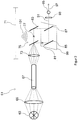
- the optical microphone 51 has a laser diode whose light is associated with a measuring head, in particular an interferometric mirror. These elements are in Fig. 2 shown in more detail.
- the optical microphone 51 may additionally comprise a piezoelectric drive element 61, which can displace the laser diode and / or the measuring head relative to the alignment point / sound source (here the valve rod), in particular to produce a multi-dimensional sound field.
- the drive element 61 can be supplied via the line 53 with electrical energy.
- the line 53 may also be formed as an optical waveguide 67 of the optical microphone 51, wherein a light source 63 is housed in the positioner housing 37 and is optically coupled via the optical waveguide 67 with a measuring head 71 of the optical microphone 51.
- the diagnostic device 55 may include a microcomputer which receives and processes, in particular evaluates, the measurement signals of the optical microphone 51.
- the microcomputer can be provided with a transmitting device, which forwards the diagnostic results or the evaluation results of a control room or a receiver, which completes a diagnosis or can display the diagnostic results.
- the microcomputer in the positioner 37 may be coupled to a memory in which both the measurement signals of the optical microphone 51 and stored comparison values, in particular empirical values, are stored in order to set the desired diagnosis.
- the optical microphone 51 comprises a light source 63, which can be embodied as a laser diode, and a measuring head 71, which can be arranged in the actuator housing 11, control valve housing 7 or otherwise in areas through which the process fluid flows.
- Light beams of the light source 63 are converged on the input lens 65, which is unnecessary for the optical microphone 51, to be concentrated in an optical fiber 67 which may be made of, for example, a flexible optical fiber cable.
- the measuring head 71 comprises a second lens 73, which bundles the light beams emerging from the optical waveguide 67 and supplies them to a beam splitter 75 at the focal point, which subdivides the collimated light beams into a first partial beam 77 and into a second partial beam 81.
- the first partial beam 77 is associated with a first mirror 83.
- the second partial beam 81 is associated with a second mirror 85, wherein both mirrors 83, 85 deflect the respective partial beam 77, 81 to a further beam splitter 87.
- the further beam splitter 87 combines the partial beams 77, 81, to a Interference arrangement 91 cause, which is assigned via a screen 93 of a photodiode 95, which emits an electrical measurement signal 97 according to the detected interference intensity.
- the second beam splitter 87 for enabling the interference viewing and the second mirror 85 are housed in a soundproof environment, such as a housing 99, while the first sub-beam 77 is exposed to sound waves 101 of the acoustic operating signal.
- a soundproof environment such as a housing 99
- the interference 91 of the partial beams 77, 81 it can be determined whether the acoustic operating signal 101 exists and how it is characterized, whereby precise conclusions can be made on the functionality / damage of the control valve 3 of the process plant.
Landscapes
- Engineering & Computer Science (AREA)
- Physics & Mathematics (AREA)
- General Engineering & Computer Science (AREA)
- General Physics & Mathematics (AREA)
- Mechanical Engineering (AREA)
- Acoustics & Sound (AREA)
- Signal Processing (AREA)
- Health & Medical Sciences (AREA)
- General Health & Medical Sciences (AREA)
- Otolaryngology (AREA)
- Life Sciences & Earth Sciences (AREA)
- Chemical & Material Sciences (AREA)
- Analytical Chemistry (AREA)
- Biochemistry (AREA)
- Immunology (AREA)
- Pathology (AREA)
- Measurement Of Mechanical Vibrations Or Ultrasonic Waves (AREA)
- Indication Of The Valve Opening Or Closing Status (AREA)
- Examining Or Testing Airtightness (AREA)
Applications Claiming Priority (1)
| Application Number | Priority Date | Filing Date | Title |
|---|---|---|---|
| DE102017100956.6A DE102017100956B4 (de) | 2017-01-18 | 2017-01-18 | Diagnosesystem und Verfahren zum Kontrollieren der Funktionsfähigkeit eines Stellgeräts zum Beeinflussen einer Prozessmediumströmung einer prozesstechnischen Anlage sowie Stellgerät |
Publications (2)
| Publication Number | Publication Date |
|---|---|
| EP3351838A1 true EP3351838A1 (fr) | 2018-07-25 |
| EP3351838B1 EP3351838B1 (fr) | 2020-05-13 |
Family
ID=60997335
Family Applications (1)
| Application Number | Title | Priority Date | Filing Date |
|---|---|---|---|
| EP18151759.0A Active EP3351838B1 (fr) | 2017-01-18 | 2018-01-16 | Microphone optique destiné au diagnostic d' appareils de réglage |
Country Status (4)
| Country | Link |
|---|---|
| US (1) | US10502341B2 (fr) |
| EP (1) | EP3351838B1 (fr) |
| CN (1) | CN208402060U (fr) |
| DE (1) | DE102017100956B4 (fr) |
Cited By (2)
| Publication number | Priority date | Publication date | Assignee | Title |
|---|---|---|---|---|
| DE102023106322A1 (de) | 2023-03-14 | 2024-09-19 | Samson Aktiengesellschaft | Feldgerätesystem, Verfahren zum Einstellen einer Prozessfluidströmung einer prozesstechnischen Anlage und prozesstechnische Anlage |
| WO2024188761A1 (fr) | 2023-03-14 | 2024-09-19 | Samson Aktiengesellschaft | Système d'appareil de terrain, procédé de surveillance d'un appareil de terrain d'une usine de traitement, et usine de traitement |
Families Citing this family (12)
| Publication number | Priority date | Publication date | Assignee | Title |
|---|---|---|---|---|
| FR3080726A1 (fr) * | 2018-04-26 | 2019-11-01 | Orange | Detecteur d'etat complexe d'un objet, oreille electronique et procede de detection |
| CN110339641A (zh) * | 2019-07-31 | 2019-10-18 | 苏州协昌环保科技股份有限公司 | 声波感知智能电磁脉冲阀以及电磁脉冲阀异常检测方法 |
| DE102019213908B4 (de) * | 2019-09-12 | 2025-06-12 | Festo Se & Co. Kg | Fluidisches System und Verfahren |
| DK180883B1 (en) * | 2019-12-02 | 2022-06-13 | Danfoss As | Cavitation sensing unit for providing a cavitation sensing signal and being adapted to be connected to a control valve of a hydrodynamic system |
| HUE060154T2 (hu) | 2020-04-03 | 2023-02-28 | Focus On V O F | Eljárás és berendezés kavitáció kimutatásához, folyadék szabályozóelemen történõ átáramlása során |
| JP2022052947A (ja) * | 2020-09-24 | 2022-04-05 | 株式会社東芝 | 回転機械異常検知装置及び回転機械異常検知方法 |
| CN113784272B (zh) * | 2021-11-10 | 2022-01-18 | 台郁电子(深圳)有限公司 | 一种多功能漏气检测仪 |
| DE102022200623A1 (de) | 2022-01-20 | 2023-07-20 | Robert Bosch Gesellschaft mit beschränkter Haftung | Prüfsystem und Prüfverfahren zur Dichtheitsprüfung einer Bipolarplatte |
| DE102022203400A1 (de) | 2022-04-06 | 2023-10-12 | Robert Bosch Gesellschaft mit beschränkter Haftung | Prüfsystem und Prüfverfahren zur Dichtheitsprüfung eines Bauteils |
| CN117267434A (zh) * | 2023-11-21 | 2023-12-22 | 上海拜安传感技术有限公司 | 一种流量控制电磁阀 |
| CN118612645A (zh) * | 2024-07-12 | 2024-09-06 | 国网江苏省电力有限公司电力科学研究院 | 一种光学麦克风测试平台及测试系统 |
| US20260035087A1 (en) * | 2024-07-31 | 2026-02-05 | The Boeing Company | Valve State Detection System and Assembly for Aircraft Fuel System and Method |
Citations (7)
| Publication number | Priority date | Publication date | Assignee | Title |
|---|---|---|---|---|
| JPS6018100A (ja) * | 1983-07-11 | 1985-01-30 | Yasushi Miki | マイクロホン |
| WO2002077733A1 (fr) * | 2001-03-22 | 2002-10-03 | Abb Patent Gmbh | Dispositif de diagnostic pour un appareil de terrain |
| DE102006013345A1 (de) * | 2006-03-23 | 2007-10-04 | Lukas Balthasar Fischer | Elektroakustischer Wandler, insbesondere optisches Mikrofon ohne Membran |
| DE102006055747A1 (de) * | 2006-11-25 | 2008-05-29 | Abb Ag | Verfahren und Anordnung zur Diagnose eines Stellorgans |
| WO2011083760A1 (fr) * | 2010-01-07 | 2011-07-14 | パナソニック株式会社 | Microphone optique |
| US20140005958A1 (en) * | 2012-06-27 | 2014-01-02 | General Monitors, Inc. | Multi-spectral ultrasonic gas leak detector |
| EP3039329A1 (fr) * | 2013-08-27 | 2016-07-06 | Fisher Controls International Llc | Procédé de détection de cavitation/clignotement dans ou à proximité d'une vanne de régulation de processus |
Family Cites Families (15)
| Publication number | Priority date | Publication date | Assignee | Title |
|---|---|---|---|---|
| US2077733A (en) * | 1935-08-13 | 1937-04-20 | Chicago Pneumatic Tool Co | Reversible rotary motor |
| DE4326343A1 (de) | 1993-08-05 | 1995-02-09 | Honeywell Ag | Diganose-System für Regel- und Absperrarmaturen |
| DE19924377B4 (de) | 1999-05-27 | 2004-12-02 | Siemens Ag | Diagnosesystem für ein von einem Stellungsregler über einen Antrieb betätigbares Ventil |
| DE19947129A1 (de) | 1999-09-30 | 2001-04-05 | Siemens Ag | Diagnosesystem und -verfahren, insbesondere für ein Ventil |
| DE102005017054B4 (de) | 2004-07-28 | 2012-01-05 | Igus - Innovative Technische Systeme Gmbh | Verfahren und Vorrichtung zur Überwachung des Zustandes von Rotorblättern an Windkraftanlagen |
| JP5043839B2 (ja) * | 2005-07-11 | 2012-10-10 | ブルックス オートメーション インコーポレイテッド | 予知保全用インテリジェント状態監視及び障害診断システム |
| DE102006059938B3 (de) | 2006-12-19 | 2008-03-13 | Abb Patent Gmbh | Verfahren zur Diagnose eines mit einer Hilfsenergie angetriebenen Stellorgans |
| DE102007045529A1 (de) | 2007-09-24 | 2009-04-23 | Siemens Ag | Diagnosesystem und Diagnoseverfahren für ein Ventil, insbesondere ein Schließventil oder ein Regelventil |
| US8306429B2 (en) * | 2009-03-30 | 2012-11-06 | Panasonic Corporation | Optical ultrasonic microphone |
| WO2013061578A1 (fr) * | 2011-10-24 | 2013-05-02 | パナソニック株式会社 | Microphone optique |
| US9638631B2 (en) * | 2014-06-10 | 2017-05-02 | Cummins Emission Solutions, Inc. | Species spatial reconstruction for exhaust system using spectroscopy and tomography |
| EP3210011A1 (fr) * | 2014-10-24 | 2017-08-30 | Renishaw Plc. | Appareil acoustique et procédé d'inspection d'objet |
| US9774698B2 (en) * | 2014-12-31 | 2017-09-26 | Netapp, Inc. | Techniques to transfer large collection containers |
| DE102015217429A1 (de) * | 2015-09-11 | 2017-03-16 | Siemens Healthcare Gmbh | Diagnosesystem und Diagnoseverfahren |
| US10255127B2 (en) * | 2015-09-30 | 2019-04-09 | International Business Machines Corporation | Optimized diagnostic data collection driven by a ticketing system |
-
2017
- 2017-01-18 DE DE102017100956.6A patent/DE102017100956B4/de active Active
- 2017-12-12 CN CN201721727798.5U patent/CN208402060U/zh active Active
-
2018
- 2018-01-16 EP EP18151759.0A patent/EP3351838B1/fr active Active
- 2018-01-18 US US15/874,260 patent/US10502341B2/en active Active
Patent Citations (7)
| Publication number | Priority date | Publication date | Assignee | Title |
|---|---|---|---|---|
| JPS6018100A (ja) * | 1983-07-11 | 1985-01-30 | Yasushi Miki | マイクロホン |
| WO2002077733A1 (fr) * | 2001-03-22 | 2002-10-03 | Abb Patent Gmbh | Dispositif de diagnostic pour un appareil de terrain |
| DE102006013345A1 (de) * | 2006-03-23 | 2007-10-04 | Lukas Balthasar Fischer | Elektroakustischer Wandler, insbesondere optisches Mikrofon ohne Membran |
| DE102006055747A1 (de) * | 2006-11-25 | 2008-05-29 | Abb Ag | Verfahren und Anordnung zur Diagnose eines Stellorgans |
| WO2011083760A1 (fr) * | 2010-01-07 | 2011-07-14 | パナソニック株式会社 | Microphone optique |
| US20140005958A1 (en) * | 2012-06-27 | 2014-01-02 | General Monitors, Inc. | Multi-spectral ultrasonic gas leak detector |
| EP3039329A1 (fr) * | 2013-08-27 | 2016-07-06 | Fisher Controls International Llc | Procédé de détection de cavitation/clignotement dans ou à proximité d'une vanne de régulation de processus |
Non-Patent Citations (1)
| Title |
|---|
| PSW STAFF: "Sennheiser Introduces Optical Microphone For Industrial & Medic", 9 March 2009 (2009-03-09), pages 1 - 6, XP055481546, Retrieved from the Internet <URL:https://www.prosoundweb.com/types/news/sennheiser_introduces_optical_microphone_for_industrial_medical_application/> [retrieved on 20180606] * |
Cited By (3)
| Publication number | Priority date | Publication date | Assignee | Title |
|---|---|---|---|---|
| DE102023106322A1 (de) | 2023-03-14 | 2024-09-19 | Samson Aktiengesellschaft | Feldgerätesystem, Verfahren zum Einstellen einer Prozessfluidströmung einer prozesstechnischen Anlage und prozesstechnische Anlage |
| WO2024188761A1 (fr) | 2023-03-14 | 2024-09-19 | Samson Aktiengesellschaft | Système d'appareil de terrain, procédé de surveillance d'un appareil de terrain d'une usine de traitement, et usine de traitement |
| DE102023106318A1 (de) | 2023-03-14 | 2024-09-19 | Samson Aktiengesellschaft | Feldgerätesystem, Verfahren zum Überwachen eines Feldgeräts einer prozesstechnischen Anlage und prozesstechnische Anlage |
Also Published As
| Publication number | Publication date |
|---|---|
| DE102017100956A1 (de) | 2018-07-19 |
| CN208402060U (zh) | 2019-01-18 |
| EP3351838B1 (fr) | 2020-05-13 |
| US20180202577A1 (en) | 2018-07-19 |
| DE102017100956B4 (de) | 2022-08-25 |
| US10502341B2 (en) | 2019-12-10 |
Similar Documents
| Publication | Publication Date | Title |
|---|---|---|
| EP3351838B1 (fr) | Microphone optique destiné au diagnostic d' appareils de réglage | |
| DE69832895T2 (de) | Methode und vorrichtung zur unauffälligen erhaltung von on-line messungen eines parameters einer prozesssteuervorichtung | |
| EP1499825B1 (fr) | Systeme et procede de diagnostique pour une vanne | |
| EP2475920B1 (fr) | Système de diagnostic pour une soupape | |
| DE102006055747B4 (de) | Verfahren und Anordnung zur Diagnose eines Stellorgans | |
| EP1216375B1 (fr) | Systeme et procede de diagnostic, notamment pour soupape | |
| DE60220438T2 (de) | Erkennung und nachweis von instabilitäten in steuerventilen | |
| DE102012016295B4 (de) | Vorrichtung und Verfahren zum Quantifizieren eines Leckagedurchflusses an einem Stellgerät | |
| DE4326343A1 (de) | Diganose-System für Regel- und Absperrarmaturen | |
| DE102014221475A1 (de) | Verfahren und Vorrichtung zur akustischen Messung von Austrittsgeschwindigkeiten und/oder Austrittsvolumenströmen von Gasen oder Flüssigkeiten | |
| EP0459946B1 (fr) | Système de surveillance, en particulier pour moteurs, compresseurs et machines productrices à travail cyclique | |
| WO2010003857A1 (fr) | Procédé de détection spectroscopique laser de gaz et détecteur de gaz | |
| EP3153820B1 (fr) | Appareil de mesure et agencement de mesure | |
| DE69416813T2 (de) | Interferenzspektrometer | |
| EP3673635B1 (fr) | Procédé de communication pour un appareil de réglage | |
| EP4428512A2 (fr) | Système de surveillance d'une installation d'hydrogène dans un véhicule et véhicule ainsi formé | |
| WO2009062708A1 (fr) | Procédé et dispositif de détermination du débit d'un fluide en écoulement | |
| DE102007018817A1 (de) | Verfahren und Vorrichtung zur Druckmessung | |
| DE102006003750A1 (de) | Verfahren zum Nachweis einer Durchführung einer Überprüfung einer Funktionsfähigkeit eines Sicherheitsventils | |
| EP3859352B1 (fr) | Îlot à soupape avec un dispositif de détection des flux de gaz dans une pluralité de canaux pneumatiques couplés acoustiquement et son utilisation | |
| DE102006059938B3 (de) | Verfahren zur Diagnose eines mit einer Hilfsenergie angetriebenen Stellorgans | |
| DE102020107661A1 (de) | Verfahren zur Druckbelastbarkeits- und Berstprüfung von Prüflingen | |
| DE102016117813A1 (de) | Tragbare Vorrichtung zum Diagnostizieren eines prozessfluidführenden Stellgeräts und Verfahren zur Diagnose des Zustands eines prozessfluidführenden Stellgeräts | |
| DE2106216A1 (de) | Akustische Fuhlervornchtung | |
| DE102013205848B3 (de) | Optisches Temperatursensorsystem |
Legal Events
| Date | Code | Title | Description |
|---|---|---|---|
| PUAI | Public reference made under article 153(3) epc to a published international application that has entered the european phase |
Free format text: ORIGINAL CODE: 0009012 |
|
| STAA | Information on the status of an ep patent application or granted ep patent |
Free format text: STATUS: THE APPLICATION HAS BEEN PUBLISHED |
|
| AK | Designated contracting states |
Kind code of ref document: A1 Designated state(s): AL AT BE BG CH CY CZ DE DK EE ES FI FR GB GR HR HU IE IS IT LI LT LU LV MC MK MT NL NO PL PT RO RS SE SI SK SM TR |
|
| AX | Request for extension of the european patent |
Extension state: BA ME |
|
| STAA | Information on the status of an ep patent application or granted ep patent |
Free format text: STATUS: REQUEST FOR EXAMINATION WAS MADE |
|
| 17P | Request for examination filed |
Effective date: 20181205 |
|
| RBV | Designated contracting states (corrected) |
Designated state(s): AL AT BE BG CH CY CZ DE DK EE ES FI FR GB GR HR HU IE IS IT LI LT LU LV MC MK MT NL NO PL PT RO RS SE SI SK SM TR |
|
| STAA | Information on the status of an ep patent application or granted ep patent |
Free format text: STATUS: EXAMINATION IS IN PROGRESS |
|
| 17Q | First examination report despatched |
Effective date: 20190118 |
|
| GRAP | Despatch of communication of intention to grant a patent |
Free format text: ORIGINAL CODE: EPIDOSNIGR1 |
|
| STAA | Information on the status of an ep patent application or granted ep patent |
Free format text: STATUS: GRANT OF PATENT IS INTENDED |
|
| RIC1 | Information provided on ipc code assigned before grant |
Ipc: G01M 3/38 20060101ALI20191105BHEP Ipc: H04R 23/00 20060101ALI20191105BHEP Ipc: G01M 3/24 20060101ALI20191105BHEP Ipc: H04R 1/02 20060101ALI20191105BHEP Ipc: F16K 37/00 20060101AFI20191105BHEP Ipc: G01H 9/00 20060101ALI20191105BHEP |
|
| INTG | Intention to grant announced |
Effective date: 20191211 |
|
| GRAS | Grant fee paid |
Free format text: ORIGINAL CODE: EPIDOSNIGR3 |
|
| GRAA | (expected) grant |
Free format text: ORIGINAL CODE: 0009210 |
|
| STAA | Information on the status of an ep patent application or granted ep patent |
Free format text: STATUS: THE PATENT HAS BEEN GRANTED |
|
| AK | Designated contracting states |
Kind code of ref document: B1 Designated state(s): AL AT BE BG CH CY CZ DE DK EE ES FI FR GB GR HR HU IE IS IT LI LT LU LV MC MK MT NL NO PL PT RO RS SE SI SK SM TR |
|
| REG | Reference to a national code |
Ref country code: GB Ref legal event code: FG4D Free format text: NOT ENGLISH |
|
| REG | Reference to a national code |
Ref country code: CH Ref legal event code: EP |
|
| REG | Reference to a national code |
Ref country code: DE Ref legal event code: R096 Ref document number: 502018001349 Country of ref document: DE |
|
| REG | Reference to a national code |
Ref country code: AT Ref legal event code: REF Ref document number: 1270733 Country of ref document: AT Kind code of ref document: T Effective date: 20200615 |
|
| REG | Reference to a national code |
Ref country code: LT Ref legal event code: MG4D |
|
| REG | Reference to a national code |
Ref country code: NL Ref legal event code: MP Effective date: 20200513 |
|
| PG25 | Lapsed in a contracting state [announced via postgrant information from national office to epo] |
Ref country code: GR Free format text: LAPSE BECAUSE OF FAILURE TO SUBMIT A TRANSLATION OF THE DESCRIPTION OR TO PAY THE FEE WITHIN THE PRESCRIBED TIME-LIMIT Effective date: 20200814 Ref country code: IS Free format text: LAPSE BECAUSE OF FAILURE TO SUBMIT A TRANSLATION OF THE DESCRIPTION OR TO PAY THE FEE WITHIN THE PRESCRIBED TIME-LIMIT Effective date: 20200913 Ref country code: SE Free format text: LAPSE BECAUSE OF FAILURE TO SUBMIT A TRANSLATION OF THE DESCRIPTION OR TO PAY THE FEE WITHIN THE PRESCRIBED TIME-LIMIT Effective date: 20200513 Ref country code: PT Free format text: LAPSE BECAUSE OF FAILURE TO SUBMIT A TRANSLATION OF THE DESCRIPTION OR TO PAY THE FEE WITHIN THE PRESCRIBED TIME-LIMIT Effective date: 20200914 Ref country code: FI Free format text: LAPSE BECAUSE OF FAILURE TO SUBMIT A TRANSLATION OF THE DESCRIPTION OR TO PAY THE FEE WITHIN THE PRESCRIBED TIME-LIMIT Effective date: 20200513 Ref country code: NO Free format text: LAPSE BECAUSE OF FAILURE TO SUBMIT A TRANSLATION OF THE DESCRIPTION OR TO PAY THE FEE WITHIN THE PRESCRIBED TIME-LIMIT Effective date: 20200813 Ref country code: LT Free format text: LAPSE BECAUSE OF FAILURE TO SUBMIT A TRANSLATION OF THE DESCRIPTION OR TO PAY THE FEE WITHIN THE PRESCRIBED TIME-LIMIT Effective date: 20200513 |
|
| PG25 | Lapsed in a contracting state [announced via postgrant information from national office to epo] |
Ref country code: LV Free format text: LAPSE BECAUSE OF FAILURE TO SUBMIT A TRANSLATION OF THE DESCRIPTION OR TO PAY THE FEE WITHIN THE PRESCRIBED TIME-LIMIT Effective date: 20200513 Ref country code: BG Free format text: LAPSE BECAUSE OF FAILURE TO SUBMIT A TRANSLATION OF THE DESCRIPTION OR TO PAY THE FEE WITHIN THE PRESCRIBED TIME-LIMIT Effective date: 20200813 Ref country code: RS Free format text: LAPSE BECAUSE OF FAILURE TO SUBMIT A TRANSLATION OF THE DESCRIPTION OR TO PAY THE FEE WITHIN THE PRESCRIBED TIME-LIMIT Effective date: 20200513 Ref country code: HR Free format text: LAPSE BECAUSE OF FAILURE TO SUBMIT A TRANSLATION OF THE DESCRIPTION OR TO PAY THE FEE WITHIN THE PRESCRIBED TIME-LIMIT Effective date: 20200513 |
|
| PG25 | Lapsed in a contracting state [announced via postgrant information from national office to epo] |
Ref country code: AL Free format text: LAPSE BECAUSE OF FAILURE TO SUBMIT A TRANSLATION OF THE DESCRIPTION OR TO PAY THE FEE WITHIN THE PRESCRIBED TIME-LIMIT Effective date: 20200513 Ref country code: NL Free format text: LAPSE BECAUSE OF FAILURE TO SUBMIT A TRANSLATION OF THE DESCRIPTION OR TO PAY THE FEE WITHIN THE PRESCRIBED TIME-LIMIT Effective date: 20200513 |
|
| PG25 | Lapsed in a contracting state [announced via postgrant information from national office to epo] |
Ref country code: DK Free format text: LAPSE BECAUSE OF FAILURE TO SUBMIT A TRANSLATION OF THE DESCRIPTION OR TO PAY THE FEE WITHIN THE PRESCRIBED TIME-LIMIT Effective date: 20200513 Ref country code: IT Free format text: LAPSE BECAUSE OF FAILURE TO SUBMIT A TRANSLATION OF THE DESCRIPTION OR TO PAY THE FEE WITHIN THE PRESCRIBED TIME-LIMIT Effective date: 20200513 Ref country code: RO Free format text: LAPSE BECAUSE OF FAILURE TO SUBMIT A TRANSLATION OF THE DESCRIPTION OR TO PAY THE FEE WITHIN THE PRESCRIBED TIME-LIMIT Effective date: 20200513 Ref country code: CZ Free format text: LAPSE BECAUSE OF FAILURE TO SUBMIT A TRANSLATION OF THE DESCRIPTION OR TO PAY THE FEE WITHIN THE PRESCRIBED TIME-LIMIT Effective date: 20200513 Ref country code: ES Free format text: LAPSE BECAUSE OF FAILURE TO SUBMIT A TRANSLATION OF THE DESCRIPTION OR TO PAY THE FEE WITHIN THE PRESCRIBED TIME-LIMIT Effective date: 20200513 Ref country code: SM Free format text: LAPSE BECAUSE OF FAILURE TO SUBMIT A TRANSLATION OF THE DESCRIPTION OR TO PAY THE FEE WITHIN THE PRESCRIBED TIME-LIMIT Effective date: 20200513 Ref country code: EE Free format text: LAPSE BECAUSE OF FAILURE TO SUBMIT A TRANSLATION OF THE DESCRIPTION OR TO PAY THE FEE WITHIN THE PRESCRIBED TIME-LIMIT Effective date: 20200513 |
|
| REG | Reference to a national code |
Ref country code: DE Ref legal event code: R097 Ref document number: 502018001349 Country of ref document: DE |
|
| PG25 | Lapsed in a contracting state [announced via postgrant information from national office to epo] |
Ref country code: PL Free format text: LAPSE BECAUSE OF FAILURE TO SUBMIT A TRANSLATION OF THE DESCRIPTION OR TO PAY THE FEE WITHIN THE PRESCRIBED TIME-LIMIT Effective date: 20200513 Ref country code: SK Free format text: LAPSE BECAUSE OF FAILURE TO SUBMIT A TRANSLATION OF THE DESCRIPTION OR TO PAY THE FEE WITHIN THE PRESCRIBED TIME-LIMIT Effective date: 20200513 |
|
| PLBE | No opposition filed within time limit |
Free format text: ORIGINAL CODE: 0009261 |
|
| STAA | Information on the status of an ep patent application or granted ep patent |
Free format text: STATUS: NO OPPOSITION FILED WITHIN TIME LIMIT |
|
| 26N | No opposition filed |
Effective date: 20210216 |
|
| PG25 | Lapsed in a contracting state [announced via postgrant information from national office to epo] |
Ref country code: SI Free format text: LAPSE BECAUSE OF FAILURE TO SUBMIT A TRANSLATION OF THE DESCRIPTION OR TO PAY THE FEE WITHIN THE PRESCRIBED TIME-LIMIT Effective date: 20200513 |
|
| PG25 | Lapsed in a contracting state [announced via postgrant information from national office to epo] |
Ref country code: MC Free format text: LAPSE BECAUSE OF FAILURE TO SUBMIT A TRANSLATION OF THE DESCRIPTION OR TO PAY THE FEE WITHIN THE PRESCRIBED TIME-LIMIT Effective date: 20200513 |
|
| REG | Reference to a national code |
Ref country code: CH Ref legal event code: PL |
|
| PG25 | Lapsed in a contracting state [announced via postgrant information from national office to epo] |
Ref country code: LU Free format text: LAPSE BECAUSE OF NON-PAYMENT OF DUE FEES Effective date: 20210116 |
|
| REG | Reference to a national code |
Ref country code: BE Ref legal event code: MM Effective date: 20210131 |
|
| PG25 | Lapsed in a contracting state [announced via postgrant information from national office to epo] |
Ref country code: LI Free format text: LAPSE BECAUSE OF NON-PAYMENT OF DUE FEES Effective date: 20210131 Ref country code: CH Free format text: LAPSE BECAUSE OF NON-PAYMENT OF DUE FEES Effective date: 20210131 |
|
| PG25 | Lapsed in a contracting state [announced via postgrant information from national office to epo] |
Ref country code: IE Free format text: LAPSE BECAUSE OF NON-PAYMENT OF DUE FEES Effective date: 20210116 |
|
| PG25 | Lapsed in a contracting state [announced via postgrant information from national office to epo] |
Ref country code: BE Free format text: LAPSE BECAUSE OF NON-PAYMENT OF DUE FEES Effective date: 20210131 |
|
| REG | Reference to a national code |
Ref country code: DE Ref legal event code: R082 Ref document number: 502018001349 Country of ref document: DE Representative=s name: SKM-IP SCHMID KRAUSS KUTTENKEULER MALESCHA SCH, DE |
|
| PG25 | Lapsed in a contracting state [announced via postgrant information from national office to epo] |
Ref country code: CY Free format text: LAPSE BECAUSE OF FAILURE TO SUBMIT A TRANSLATION OF THE DESCRIPTION OR TO PAY THE FEE WITHIN THE PRESCRIBED TIME-LIMIT Effective date: 20200513 |
|
| PG25 | Lapsed in a contracting state [announced via postgrant information from national office to epo] |
Ref country code: HU Free format text: LAPSE BECAUSE OF FAILURE TO SUBMIT A TRANSLATION OF THE DESCRIPTION OR TO PAY THE FEE WITHIN THE PRESCRIBED TIME-LIMIT; INVALID AB INITIO Effective date: 20180116 |
|
| P01 | Opt-out of the competence of the unified patent court (upc) registered |
Effective date: 20230713 |
|
| REG | Reference to a national code |
Ref country code: AT Ref legal event code: MM01 Ref document number: 1270733 Country of ref document: AT Kind code of ref document: T Effective date: 20230116 |
|
| PG25 | Lapsed in a contracting state [announced via postgrant information from national office to epo] |
Ref country code: AT Free format text: LAPSE BECAUSE OF NON-PAYMENT OF DUE FEES Effective date: 20230116 |
|
| PG25 | Lapsed in a contracting state [announced via postgrant information from national office to epo] |
Ref country code: MK Free format text: LAPSE BECAUSE OF FAILURE TO SUBMIT A TRANSLATION OF THE DESCRIPTION OR TO PAY THE FEE WITHIN THE PRESCRIBED TIME-LIMIT Effective date: 20200513 Ref country code: AT Free format text: LAPSE BECAUSE OF NON-PAYMENT OF DUE FEES Effective date: 20230116 |
|
| PG25 | Lapsed in a contracting state [announced via postgrant information from national office to epo] |
Ref country code: TR Free format text: LAPSE BECAUSE OF FAILURE TO SUBMIT A TRANSLATION OF THE DESCRIPTION OR TO PAY THE FEE WITHIN THE PRESCRIBED TIME-LIMIT Effective date: 20200513 |
|
| PG25 | Lapsed in a contracting state [announced via postgrant information from national office to epo] |
Ref country code: MT Free format text: LAPSE BECAUSE OF FAILURE TO SUBMIT A TRANSLATION OF THE DESCRIPTION OR TO PAY THE FEE WITHIN THE PRESCRIBED TIME-LIMIT Effective date: 20200513 |
|
| PGFP | Annual fee paid to national office [announced via postgrant information from national office to epo] |
Ref country code: GB Payment date: 20260123 Year of fee payment: 9 |
|
| PGFP | Annual fee paid to national office [announced via postgrant information from national office to epo] |
Ref country code: DE Payment date: 20260121 Year of fee payment: 9 |
|
| PGFP | Annual fee paid to national office [announced via postgrant information from national office to epo] |
Ref country code: AT Payment date: 20260410 Year of fee payment: 5 |
|
| PGFP | Annual fee paid to national office [announced via postgrant information from national office to epo] |
Ref country code: FR Payment date: 20260123 Year of fee payment: 9 |