EP3351982A1 - Fibre optique et système de transmission optique - Google Patents
Fibre optique et système de transmission optique Download PDFInfo
- Publication number
- EP3351982A1 EP3351982A1 EP16846001.2A EP16846001A EP3351982A1 EP 3351982 A1 EP3351982 A1 EP 3351982A1 EP 16846001 A EP16846001 A EP 16846001A EP 3351982 A1 EP3351982 A1 EP 3351982A1
- Authority
- EP
- European Patent Office
- Prior art keywords
- optical fiber
- smaller
- holes
- mode
- light
- Prior art date
- Legal status (The legal status is an assumption and is not a legal conclusion. Google has not performed a legal analysis and makes no representation as to the accuracy of the status listed.)
- Withdrawn
Links
Images









Classifications
-
- G—PHYSICS
- G02—OPTICS
- G02B—OPTICAL ELEMENTS, SYSTEMS OR APPARATUS
- G02B6/00—Light guides; Structural details of arrangements comprising light guides and other optical elements, e.g. couplings
- G02B6/02—Optical fibres with cladding with or without a coating
- G02B6/02295—Microstructured optical fibre
- G02B6/02314—Plurality of longitudinal structures extending along optical fibre axis, e.g. holes
- G02B6/02342—Plurality of longitudinal structures extending along optical fibre axis, e.g. holes characterised by cladding features, i.e. light confining region
- G02B6/02347—Longitudinal structures arranged to form a regular periodic lattice, e.g. triangular, square, honeycomb unit cell repeated throughout cladding
-
- G—PHYSICS
- G02—OPTICS
- G02B—OPTICAL ELEMENTS, SYSTEMS OR APPARATUS
- G02B6/00—Light guides; Structural details of arrangements comprising light guides and other optical elements, e.g. couplings
- G02B6/02—Optical fibres with cladding with or without a coating
-
- G—PHYSICS
- G02—OPTICS
- G02B—OPTICAL ELEMENTS, SYSTEMS OR APPARATUS
- G02B6/00—Light guides; Structural details of arrangements comprising light guides and other optical elements, e.g. couplings
- G02B6/02—Optical fibres with cladding with or without a coating
- G02B6/02295—Microstructured optical fibre
- G02B6/02314—Plurality of longitudinal structures extending along optical fibre axis, e.g. holes
-
- G—PHYSICS
- G02—OPTICS
- G02B—OPTICAL ELEMENTS, SYSTEMS OR APPARATUS
- G02B6/00—Light guides; Structural details of arrangements comprising light guides and other optical elements, e.g. couplings
- G02B6/02—Optical fibres with cladding with or without a coating
- G02B6/02295—Microstructured optical fibre
- G02B6/02314—Plurality of longitudinal structures extending along optical fibre axis, e.g. holes
- G02B6/02319—Plurality of longitudinal structures extending along optical fibre axis, e.g. holes characterised by core or core-cladding interface features
- G02B6/02333—Core having higher refractive index than cladding, e.g. solid core, effective index guiding
-
- G—PHYSICS
- G02—OPTICS
- G02B—OPTICAL ELEMENTS, SYSTEMS OR APPARATUS
- G02B6/00—Light guides; Structural details of arrangements comprising light guides and other optical elements, e.g. couplings
- G02B6/02—Optical fibres with cladding with or without a coating
- G02B6/032—Optical fibres with cladding with or without a coating with non solid core or cladding
-
- G—PHYSICS
- G02—OPTICS
- G02B—OPTICAL ELEMENTS, SYSTEMS OR APPARATUS
- G02B6/00—Light guides; Structural details of arrangements comprising light guides and other optical elements, e.g. couplings
- G02B6/24—Coupling light guides
- G02B6/42—Coupling light guides with opto-electronic elements
-
- G—PHYSICS
- G02—OPTICS
- G02B—OPTICAL ELEMENTS, SYSTEMS OR APPARATUS
- G02B6/00—Light guides; Structural details of arrangements comprising light guides and other optical elements, e.g. couplings
- G02B6/24—Coupling light guides
- G02B6/42—Coupling light guides with opto-electronic elements
- G02B6/4201—Packages, e.g. shape, construction, internal or external details
- G02B6/4204—Packages, e.g. shape, construction, internal or external details the coupling comprising intermediate optical elements, e.g. lenses, holograms
- G02B6/4206—Optical features
-
- B—PERFORMING OPERATIONS; TRANSPORTING
- B23—MACHINE TOOLS; METAL-WORKING NOT OTHERWISE PROVIDED FOR
- B23K—SOLDERING OR UNSOLDERING; WELDING; CLADDING OR PLATING BY SOLDERING OR WELDING; CUTTING BY APPLYING HEAT LOCALLY, e.g. FLAME CUTTING; WORKING BY LASER BEAM
- B23K26/00—Working by laser beam, e.g. welding, cutting or boring
- B23K26/70—Auxiliary operations or equipment
- B23K26/702—Auxiliary equipment
-
- G—PHYSICS
- G02—OPTICS
- G02B—OPTICAL ELEMENTS, SYSTEMS OR APPARATUS
- G02B6/00—Light guides; Structural details of arrangements comprising light guides and other optical elements, e.g. couplings
- G02B6/02—Optical fibres with cladding with or without a coating
- G02B6/028—Optical fibres with cladding with or without a coating with core or cladding having graded refractive index
- G02B6/0288—Multimode fibre, e.g. graded index core for compensating modal dispersion
Definitions
- the present invention relates to high-power optical transmission using an optical fiber.
- High-output fiber lasers with an output of as high as 10 kW are developed and are expected to be used in medical and industrial fields.
- a core area is expanded in a short optical fiber of several meters or shorter, so that output power limitation due to nonlinearity is relaxed.
- a beam quality of emitted light significantly affects processing efficiency. Since the beam quality strongly depends on a mode state of the emitted light, an optical fiber enabling single mode transmission is used in the fiber laser.
- an optical fiber is connected to an emission end of the above-described high-output laser to be applied to remote welding processing.
- the beam quality at the emission end is affected by an excitation state of a high-order mode in the connected optical fiber. Therefore, if a multimode optical fiber with a large core area is connected as a transmission optical fiber, high-power light of several kW may be transmitted over several tens of meters or longer, but the beam quality at the emission end is low.
- the number of modes that can be propagated using a photonic crystal fiber is set to be a LP21 mode or lower order modes
- an axial shift amount between a central axis of a laser oscillating unit and a central axis of the photonic crystal fiber is set to be a certain amount or smaller
- a predetermined bending radius is set for arbitrary output light power and transmission distance, thereby solving the problem.
- maximum output light power P th for preventing stimulated Raman scattering and an effective interaction length L eff are in an inverse relationship.
- L eff and a transmission distance L have equivalent values.
- an output light power performance may be represented by a product (kW ⁇ m) of the output light power and the transmission distance.
- an optical fiber according to the present invention is an optical fiber in which a plurality of holes is arranged along a longitudinal direction of the optical fiber and a region surrounded by the plurality of holes is formed as a core region, the optical fiber having a predetermined bending radius determined according to a transmission distance of the optical fiber and light power output from the optical fiber, and an inter-hole distance of the plurality of holes and a ratio between a hole diameter of the plurality of holes and the inter-hole distance such that light of a predetermined number of modes is transmitted and a bending loss of light of a fundamental mode with the predetermined bending radius becomes a predetermined value or smaller.
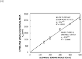
- An effective cross-sectional area A eff of the optical fiber and the predetermined bending radius R may have a relationship represented by following expression (1).
- a coefficient a may be 6.6 or larger and 6.9 or smaller, and a coefficient b may be 0.97 or larger.
- the predetermined bending radius may be 500 mm or smaller, a hole defect corresponding to one hole forming the core region may be included in the plurality of holes, the inter-hole distance between the plurality of holes may be 60 ⁇ m or smaller, and the ratio between the hole diameter of the plurality of holes and the inter-hole distance may be 0.78 or smaller.
- the predetermined bending radius may be 500 mm or smaller, a hole defect corresponding to seven holes forming the core region may be included in the plurality of holes, the inter-hole distance between the plurality of holes may be 28.5 ⁇ m or smaller, and the ratio between the hole diameter of the plurality of holes and the inter-hole distance may be 0.55 or smaller.
- the number of the plurality of holes may be 18 or smaller.
- the number of the plurality of holes may be 12, the inter-hole distance between the plurality of holes may be 50 ⁇ m or larger and 65 ⁇ m or smaller, and the ratio of the hole diameter of the plurality of holes to the inter-hole distance may be 0.79 or larger and 0.88 or smaller.
- the light of the predetermined number of modes may be the light including a LP01 mode, a LP11 mode, and a LP21 mode but not including a LP02 mode.
- the light of the predetermined number of modes may be the light including a LP01 mode and a LP11 mode but not including the LP21 mode and a higher order mode.
- the predetermined value may be 1 dB/km.
- an optical fiber according to the present invention is provided with the optical fiber according to the present invention, a light source that emits light transmitted by the optical fiber, and a coupling unit that sets an axial shift amount between a central axis of emitted light from the light source and a central axis of the core region to 0.95 or smaller with respect to a mode field radius of the optical fiber.
- An optical fiber of the present invention has an effect of obtaining high-beam quality and high-output output light as compared to that of the conventional optical fiber by setting a bending radius to a predetermined value in a photonic crystal fiber.
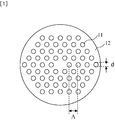
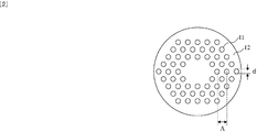
- FIGS. 1 to 3 illustrate structural examples of a high-power optical transmission optical fiber according to the embodiment.
- the high-power optical transmission optical fiber according to this embodiment uses a photonic crystal fiber (PCF) having a plurality of holes along a longitudinal direction of the optical fiber as represented by FIG. 1 or FIG. 2 .
- FIGS. 1 and 2 illustrate first and second structural examples of the high-power optical transmission optical fiber according to this embodiment, respectively.
- An optical fiber cable 83 according to the embodiment is provided with two or more optical fibers and at least one of the two or more optical fibers is the high-power optical transmission optical fiber according to this embodiment as illustrated in FIG. 3 .
- FIGS. 1 and 2 a plurality of holes is arranged in a hexagonal close-packed manner in a uniform material (for example, pure quartz), and a hole defect is arranged at the center to make a region with the hole defect a core region in which an optical wave propagates.
- FIG. 1 illustrates an example in which one hole defect is arranged at the center
- FIG. 2 illustrates an example in which seven hole defects are arranged at the center.
- a high-power optical transmission optical fiber 91 sets a bending radius when a cable is obtained as illustrated in FIG. 3 to a predetermined value.
- the high-power optical transmission optical fiber according to this embodiment simultaneously realizes the core region expansion and limitation of the number of propagation modes, thereby realizing high-quality and high-power output light.
- a predetermined lower limit value may be determined in operation when setting the bending radius, it is preferable to select as a covering of the optical fiber cable 83 a material having rigidity such that this does not bend so as to excess a predetermined bending radius.
- the bending radius of the high-power optical transmission optical fiber 91 it is preferable to take bending in the optical fiber cable 83 into consideration in addition to a bending radius R of the optical fiber cable 83 itself. In this case, note that it is R + D/2 with respect to an outer diameter D of the optical fiber cable 83.
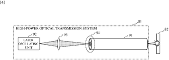
- the high-power optical transmission system in this embodiment includes a laser oscillating unit 92, a coupling unit 94 for allowing emitted light from the laser oscillating unit 92 to be incident on the high-power optical transmission optical fiber 91, and the high-power optical transmission optical fiber 91 for guiding an incident optical wave.
- a lens 93 for controlling an incident angle may be inserted between the laser oscillating unit 92 and the coupling unit 94.
- FIG. 5 illustrates the coupling efficiency due to mode field diameter (MFD) mismatch between the incident light and the photonic crystal fiber.
- the coupling efficiency from a LP01 mode which is a fundamental mode to LP11, LP21, and LP02 modes is plotted along a vertical axis.
- a ratio of a beam diameter of the incident light to the MFD of the photonic crystal fiber is plotted along a horizontal axis.
- MFD mode field diameter
- the beam diameter of the incident light and the MFD of the photonic crystal fiber are completely identical to each other.
- the coupling efficiency for the LP11 and LP21 modes is significantly small such as 0.05 or smaller. This is because electric field distribution of the LP11 mode and the LP21 mode does not have a component in the vicinity of the center of the optical fiber, so that no coupling with the incident light occurs.
- the high-power optical transmission optical fiber 91 and the transmission system of this embodiment may stably obtain high-quality output light without depending on a degree of the MFD mismatch between the incident light from the laser oscillating unit 92 and the transmission optical fiber 91.
- FIG. 6 illustrates a change in an inter-mode power ratio and M 2 representing the beam quality of the emitted light due to an axial shift.
- An axial shift amount of the center of the incident light from the center of the fiber is plotted along the horizontal axis.
- this is expressed by a relative value with respect to a mode field radius of the LP01 mode.
- the inter-mode power ratio indicates the power ratio of the LP11 mode or LP21 mode to the LP01, that is, the coupling efficiency between the modes.
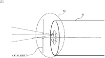
- the high-power optical transmission system of this embodiment as illustrated in FIG. 7 , in the coupling unit 94, the axial shift amount between a central axis of the laser oscillating unit 92, that is, an optical axis of the output light of the laser oscillating unit 92 and a central axis of the core region of the high-power optical transmission optical fiber 91 is set to 0.95 or smaller with respect to the mode field radius of the high-power optical transmission optical fiber 91.
- the high-power optical transmission system of this embodiment may obtain extremely high-quality output light with M 2 of 2.0 or smaller.
- FIGS. 8 and 9 illustrate examples of a structural condition of the PCF of the high-power optical transmission optical fiber according to this embodiment.
- FIGS. 8 and 9 illustrate cases where there are one hole defect and seven hole defects as illustrated in FIGS. 1 and 2 , respectively.
- the drawings illustrate the structural conditions at a wavelength of 1060 nm.
- a solid line indicates the structural condition that a loss for the LP02 mode is 0.1 dB/m, and the LP02 mode does not propagate in a region under and to the left of the solid line.
- a broken line indicates the structural condition that the bending loss of the fundamental mode is 1 dB/km with the bending radius R illustrated in the drawing, and it is possible to sufficiently decrease the bending loss for the fundamental mode in a region to the left of the broken line, and obtain a low-loss high-power optical transmission optical fiber and the optical fiber cable 83.
- a maximum value of the output light power may increase as an effective cross-sectional area of the fundamental mode expands, and the effective cross-sectional area may be expanded as an inter-hole interval ⁇ of the PCF increases. Therefore, at an intersection of the solid line and the broken line, the propagation of the LP02 mode and the increase in bending loss may be simultaneously prevented, and the effective cross-sectional area may be maximized with the bending radius corresponding to the broken line.
- the conditions capable of simultaneously preventing the propagation of the LP02 mode and the increase in the bending loss and maximizing the effective cross-sectional area with the bending radius corresponding to the broken line are as follows.
- ⁇ 60 ⁇ m or smaller and d/ ⁇ is 0.78 or smaller.
- ⁇ 400 mm or smaller, ⁇ is 55.5 ⁇ m or smaller and d/ ⁇ is 0.775 or smaller.
- ⁇ 51 ⁇ m or smaller and d/ ⁇ is 0.77 or smaller.
- ⁇ 44 ⁇ m or smaller and d/ ⁇ is 0.755 or smaller.
- ⁇ 32 ⁇ m or smaller and d/ ⁇ is 0.72 or smaller.
- the conditions capable of simultaneously preventing the propagation of the LP02 mode and the increase in the bending loss and maximizing the effective cross-sectional area with the bending radius corresponding to the broken line are as follows.
- ⁇ 28.5 ⁇ m or smaller and d/ ⁇ is 0.55 or smaller.
- ⁇ 400 mm or smaller, ⁇ is 23 ⁇ m or smaller and d/ ⁇ is 0.48 or smaller.
- ⁇ 300 mm or smaller, ⁇ is 20 ⁇ m or smaller and d/ ⁇ is 0.45 or smaller.
- ⁇ 15 ⁇ m or smaller and d/ ⁇ is 0.38 or smaller.
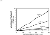
- FIGS. 10 and 11 illustrate relationships between the effective cross-sectional area and the maximum output light power, and an allowable bending radius of the optical fiber, respectively.
- the effective cross-sectional area is plotted along a vertical axis in which ⁇ represents a case where there are seven hole defects illustrated in FIG. 9 , and ⁇ represents a case where there is one hole defect illustrated in FIG. 8 .
- the maximum output light power at each transmission distance is plotted along the vertical axis, in which L represents a transmission distance (m). Results in the drawings correspond to the structures obtained at the intersections of the solid line and the broken line in FIGS. 8 and 9 .
- the relationship between the allowable bending radius and the effective cross-sectional area is less dependent on the number of hole defects, and as described, a in expression (1) is 6.6 to 6.9, and b is approximately 1.0.
- a in expression (1) is 6.6 to 6.9
- b is approximately 1.0.
- FIG. 11 by using the PCF obtained by the above-described structural design, when considering a transmission distance of approximately 50 m, for example, an output of 1 kW or larger may be obtained even under severe conditions such as the allowable bending radius of 50 mm or smaller, and if the allowable bending radius is increased to 500 mm, an output close to 10 kW may be obtained.
- the allowable bending radius By setting the allowable bending radius to approximately 300 mm, it may be confirmed that high-power light of 1 kW or larger may be transmitted over a long distance of 300 m or longer.
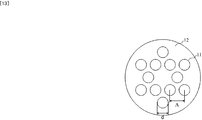
- FIGS. 12 and 13 illustrate third and fourth structural examples of the high-power optical transmission optical fiber of this embodiment.
- the third and fourth structural examples illustrate optical fiber structures configured with a small number of holes.
- the core region corresponds to one hole defect
- the numbers of holes are 18 and 12 in FIGS. 12 and FIG. 13 , respectively.
- accuracy of positions and sizes of the respective holes affects an optical characteristic, and as the number of holes increases, difficulty in manufacturing and deterioration in yield of the structure become remarkable.
- FIGS. 12 and 13 illustrates third and fourth structural examples of the high-power optical transmission optical fiber of this embodiment.
- the third and fourth structural examples illustrate optical fiber structures configured with a small number of holes.
- the core region corresponds to one hole defect
- the numbers of holes are 18 and 12 in FIGS. 12 and FIG. 13 , respectively.
- accuracy of positions and sizes of the respective holes affects an optical characteristic, and as the number of holes increases, difficulty in manufacturing and deterioration in yield of the structure become remarkable.
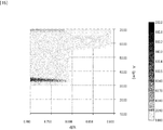
- FIGS. 14 to 17 illustrate design examples in a case where the number of holes is set to 12 in the high-power optical transmission optical fiber of this embodiment.
- FIG. 14 illustrates a structural range in which the bending loss for the fundamental mode is 0.1 dB/m or smaller.
- FIGS. 15 , 16 , and 17 illustrate loss values for the LP11 mode, LP21 mode, and LP02 mode, respectively, and the loss of a target mode becomes sufficiently large in a region surrounded by a frame and may be leaked.
- the object may be achieved in an overlapping range of FIG. 14 and FIG. 17 illustrated in FIG. 18 . That is, a structure in which ⁇ is 50 ⁇ m or larger and 65 ⁇ m or smaller and d/ ⁇ is 0.79 or larger and 0.88 or smaller, or ⁇ is 50 ⁇ m or smaller and d/ ⁇ is 0.7 or larger and 0.79 or smaller is suitable. At that time, since the number of holes is as small as 12, yield and manufacturing accuracy in manufacturing are extremely excellent, and the kW class output light with M 2 of 2.0 or smaller is obtained, so that this is preferable.
- the configuration is such that the predetermined number of modes is three and the LP01 being the fundamental mode and the LP11 and LP21 are propagated but the LP02 is not propagated in this embodiment, but the present invention is not limited thereto.
- the configuration may be such that the predetermined number of modes is two and the LP01 mode and LP11 mode are propagated but the LP21 mode and higher order modes are not propagated. According to this, the effect similar to that of this embodiment may be obtained.
- FIGS. 15 and 16 illustrate structures in which the LP11 mode and the LP21 mode leak, respectively, and it is possible to set the number of modes to two by using an overlapping region of FIGS. 14 and 15 and to set the number of modes to three by using an overlapping region of FIGS. 14 and 16 .
- ⁇ is 30 ⁇ m or larger and 55 ⁇ m or smaller and d/ ⁇ is 0.70 or larger and 0.79 or smaller, or ⁇ is 55 ⁇ m or larger and 65 ⁇ m or smaller and d/ ⁇ is 0.79 or larger and 0.83 or smaller, or ⁇ is 57 ⁇ m or larger and 65 ⁇ m or smaller and d/ ⁇ is 0.83 or larger and 0.88 or smaller, or ⁇ is 59 ⁇ m or larger and 68 ⁇ m or smaller and d/ ⁇ is 0.88 or larger and 0.89 or smaller.
- ⁇ is 52 ⁇ m or larger and 65 ⁇ m or smaller and d/ ⁇ is 0.79 or larger and 0.88 or smaller, or ⁇ is 52 ⁇ m or smaller and d/ ⁇ is 0.7 or larger and 0.77 or smaller.
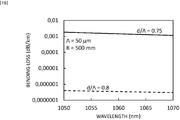
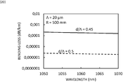
- FIGS. 19 and 20 illustrate examples of the bending loss with respect to a wavelength.
- FIG. 19 illustrates, as an example, a case where ⁇ of 50.0 ⁇ m and d/ ⁇ is 0.75 or 0.8 and the bending radius R of the PCF with one hole defect is set to 500 mm.
- FIG. 20 illustrates, as an example, a case where ⁇ is 20.0 ⁇ m and d/ ⁇ is 0.45 or 0.8 and the bending radius R of the PCF with seven hole defects is set to 500 mm. It is understood that there is no change in the bending loss between the wavelength of 1060 nm and the wavelength of 1050 nm. For this reason, this embodiment is not limited to the wavelength of 1060 nm exemplified under the structural conditions in FIGS. 8 and 9 , and is similarly applicable in a range from the wavelength of 1050 nm or longer to 1070 nm or shorter.
- the present invention may be used in industrial processing using high-power light.
Landscapes
- Physics & Mathematics (AREA)
- General Physics & Mathematics (AREA)
- Optics & Photonics (AREA)
- Optical Fibers, Optical Fiber Cores, And Optical Fiber Bundles (AREA)
- Optical Couplings Of Light Guides (AREA)
Applications Claiming Priority (2)
| Application Number | Priority Date | Filing Date | Title |
|---|---|---|---|
| JP2015185252 | 2015-09-18 | ||
| PCT/JP2016/056659 WO2017047128A1 (fr) | 2015-09-18 | 2016-03-03 | Fibre optique et système de transmission optique |
Publications (2)
| Publication Number | Publication Date |
|---|---|
| EP3351982A1 true EP3351982A1 (fr) | 2018-07-25 |
| EP3351982A4 EP3351982A4 (fr) | 2019-06-26 |
Family
ID=58288598
Family Applications (1)
| Application Number | Title | Priority Date | Filing Date |
|---|---|---|---|
| EP16846001.2A Withdrawn EP3351982A4 (fr) | 2015-09-18 | 2016-03-03 | Fibre optique et système de transmission optique |
Country Status (5)
| Country | Link |
|---|---|
| US (1) | US10444428B2 (fr) |
| EP (1) | EP3351982A4 (fr) |
| JP (1) | JP6446140B2 (fr) |
| CN (1) | CN107924022B (fr) |
| WO (1) | WO2017047128A1 (fr) |
Families Citing this family (2)
| Publication number | Priority date | Publication date | Assignee | Title |
|---|---|---|---|---|
| CN117546067A (zh) | 2021-08-02 | 2024-02-09 | 日本电信电话株式会社 | 光子晶体光纤 |
| CN117347014B (zh) * | 2023-12-04 | 2024-02-13 | 武汉光谷航天三江激光产业技术研究院有限公司 | 光纤基模及高阶模弯曲损耗测试方法及系统 |
Family Cites Families (14)
| Publication number | Priority date | Publication date | Assignee | Title |
|---|---|---|---|---|
| JPS5720681B2 (fr) | 1973-09-28 | 1982-04-30 | ||
| US7280730B2 (en) * | 2004-01-16 | 2007-10-09 | Imra America, Inc. | Large core holey fibers |
| US7190869B2 (en) * | 2004-10-29 | 2007-03-13 | The Hong Kong Polytechnic University | Two-mode photonic crystal fiber and applications thereof |
| EP2201415B1 (fr) | 2007-09-26 | 2019-07-03 | Imra America, Inc. | Fibres optiques en verre à âme de grande dimension |
| JP2011522288A (ja) * | 2008-05-30 | 2011-07-28 | コーニング インコーポレイテッド | フォトニックバンドギャップ光ファイバを用いるファイバ集合体 |
| CN101408641B (zh) | 2008-11-06 | 2010-12-15 | 燕山大学 | 锥形微结构光纤高阶模滤波器 |
| JP5059797B2 (ja) * | 2009-02-25 | 2012-10-31 | 日本電信電話株式会社 | 光ファイバ、光ファイバの設計方法及び光波長多重通信システム |
| EP2549306A1 (fr) | 2010-03-16 | 2013-01-23 | Furukawa Electric Co., Ltd. | Fibre à trous |
| CN102213792B (zh) * | 2011-06-09 | 2013-03-27 | 华中科技大学 | 一种大模场有源光纤及其制备方法 |
| CN102435986A (zh) * | 2011-09-16 | 2012-05-02 | 北方民族大学 | 全光纤激光雷达单模光纤自动耦合系统 |
| JPWO2013051295A1 (ja) | 2011-10-04 | 2015-03-30 | 古河電気工業株式会社 | 光ファイバおよび光伝送システム |
| CN102375176B (zh) * | 2011-11-11 | 2013-10-23 | 江苏大学 | 一种低弯曲损耗光纤 |
| US9366810B2 (en) | 2012-08-29 | 2016-06-14 | Ofs Fitel, Llc | Double-clad, gain-producing fibers with increased cladding absoroption while maintaining single-mode operation |
| JP5843366B2 (ja) | 2012-12-14 | 2016-01-13 | 日本電信電話株式会社 | 光ファイバ |
-
2016
- 2016-03-03 US US15/752,809 patent/US10444428B2/en active Active
- 2016-03-03 CN CN201680049939.4A patent/CN107924022B/zh active Active
- 2016-03-03 EP EP16846001.2A patent/EP3351982A4/fr not_active Withdrawn
- 2016-03-03 WO PCT/JP2016/056659 patent/WO2017047128A1/fr not_active Ceased
- 2016-03-03 JP JP2017540526A patent/JP6446140B2/ja active Active
Also Published As
| Publication number | Publication date |
|---|---|
| US20190004246A1 (en) | 2019-01-03 |
| EP3351982A4 (fr) | 2019-06-26 |
| CN107924022A (zh) | 2018-04-17 |
| JP6446140B2 (ja) | 2018-12-26 |
| WO2017047128A1 (fr) | 2017-03-23 |
| JPWO2017047128A1 (ja) | 2018-01-25 |
| US10444428B2 (en) | 2019-10-15 |
| CN107924022B (zh) | 2020-07-03 |
Similar Documents
| Publication | Publication Date | Title |
|---|---|---|
| US10539784B2 (en) | Photonic crystal fiber and high-power light transmission system | |
| JP2016173472A (ja) | 光伝送装置及び光伝送方法 | |
| US10816722B2 (en) | Optical fiber design method | |
| EP3351982A1 (fr) | Fibre optique et système de transmission optique | |
| US10310177B2 (en) | Photonic crystal fiber | |
| US12548966B2 (en) | Multiple signal fiber, optical pump-signal combiner |
Legal Events
| Date | Code | Title | Description |
|---|---|---|---|
| STAA | Information on the status of an ep patent application or granted ep patent |
Free format text: STATUS: THE INTERNATIONAL PUBLICATION HAS BEEN MADE |
|
| PUAI | Public reference made under article 153(3) epc to a published international application that has entered the european phase |
Free format text: ORIGINAL CODE: 0009012 |
|
| STAA | Information on the status of an ep patent application or granted ep patent |
Free format text: STATUS: REQUEST FOR EXAMINATION WAS MADE |
|
| 17P | Request for examination filed |
Effective date: 20180417 |
|
| AK | Designated contracting states |
Kind code of ref document: A1 Designated state(s): AL AT BE BG CH CY CZ DE DK EE ES FI FR GB GR HR HU IE IS IT LI LT LU LV MC MK MT NL NO PL PT RO RS SE SI SK SM TR |
|
| AX | Request for extension of the european patent |
Extension state: BA ME |
|
| DAV | Request for validation of the european patent (deleted) | ||
| DAX | Request for extension of the european patent (deleted) | ||
| A4 | Supplementary search report drawn up and despatched |
Effective date: 20190529 |
|
| RIC1 | Information provided on ipc code assigned before grant |
Ipc: G02B 6/02 20060101AFI20190523BHEP Ipc: G02B 6/032 20060101ALI20190523BHEP Ipc: G02B 6/42 20060101ALI20190523BHEP Ipc: G02B 6/028 20060101ALI20190523BHEP |
|
| STAA | Information on the status of an ep patent application or granted ep patent |
Free format text: STATUS: EXAMINATION IS IN PROGRESS |
|
| 17Q | First examination report despatched |
Effective date: 20200309 |
|
| STAA | Information on the status of an ep patent application or granted ep patent |
Free format text: STATUS: THE APPLICATION IS DEEMED TO BE WITHDRAWN |
|
| 18D | Application deemed to be withdrawn |
Effective date: 20250514 |