EP3352008A1 - Dünnschichtheizer für kameramodul und kameramodul damit - Google Patents
Dünnschichtheizer für kameramodul und kameramodul damit Download PDFInfo
- Publication number
- EP3352008A1 EP3352008A1 EP16846835.3A EP16846835A EP3352008A1 EP 3352008 A1 EP3352008 A1 EP 3352008A1 EP 16846835 A EP16846835 A EP 16846835A EP 3352008 A1 EP3352008 A1 EP 3352008A1
- Authority
- EP
- European Patent Office
- Prior art keywords
- electrode
- thin film
- camera module
- heating
- heating body
- Prior art date
- Legal status (The legal status is an assumption and is not a legal conclusion. Google has not performed a legal analysis and makes no representation as to the accuracy of the status listed.)
- Granted
Links
Images




Classifications
-
- G—PHYSICS
- G02—OPTICS
- G02B—OPTICAL ELEMENTS, SYSTEMS OR APPARATUS
- G02B7/00—Mountings, adjusting means, or light-tight connections, for optical elements
- G02B7/02—Mountings, adjusting means, or light-tight connections, for optical elements for lenses
- G02B7/028—Mountings, adjusting means, or light-tight connections, for optical elements for lenses with means for compensating for changes in temperature or for controlling the temperature; thermal stabilisation
-
- G—PHYSICS
- G02—OPTICS
- G02B—OPTICAL ELEMENTS, SYSTEMS OR APPARATUS
- G02B27/00—Optical systems or apparatus not provided for by any of the groups G02B1/00 - G02B26/00, G02B30/00
-
- G—PHYSICS
- G02—OPTICS
- G02B—OPTICAL ELEMENTS, SYSTEMS OR APPARATUS
- G02B27/00—Optical systems or apparatus not provided for by any of the groups G02B1/00 - G02B26/00, G02B30/00
- G02B27/0006—Optical systems or apparatus not provided for by any of the groups G02B1/00 - G02B26/00, G02B30/00 with means to keep optical surfaces clean, e.g. by preventing or removing dirt, stains, contamination, condensation
-
- G—PHYSICS
- G03—PHOTOGRAPHY; CINEMATOGRAPHY; ANALOGOUS TECHNIQUES USING WAVES OTHER THAN OPTICAL WAVES; ELECTROGRAPHY; HOLOGRAPHY
- G03B—APPARATUS OR ARRANGEMENTS FOR TAKING PHOTOGRAPHS OR FOR PROJECTING OR VIEWING THEM; APPARATUS OR ARRANGEMENTS EMPLOYING ANALOGOUS TECHNIQUES USING WAVES OTHER THAN OPTICAL WAVES; ACCESSORIES THEREFOR
- G03B17/00—Details of cameras or camera bodies; Accessories therefor
- G03B17/02—Bodies
- G03B17/12—Bodies with means for supporting objectives, supplementary lenses, filters, masks, or turrets
-
- G—PHYSICS
- G03—PHOTOGRAPHY; CINEMATOGRAPHY; ANALOGOUS TECHNIQUES USING WAVES OTHER THAN OPTICAL WAVES; ELECTROGRAPHY; HOLOGRAPHY
- G03B—APPARATUS OR ARRANGEMENTS FOR TAKING PHOTOGRAPHS OR FOR PROJECTING OR VIEWING THEM; APPARATUS OR ARRANGEMENTS EMPLOYING ANALOGOUS TECHNIQUES USING WAVES OTHER THAN OPTICAL WAVES; ACCESSORIES THEREFOR
- G03B17/00—Details of cameras or camera bodies; Accessories therefor
- G03B17/55—Details of cameras or camera bodies; Accessories therefor with provision for heating or cooling, e.g. in aircraft
-
- H—ELECTRICITY
- H04—ELECTRIC COMMUNICATION TECHNIQUE
- H04N—PICTORIAL COMMUNICATION, e.g. TELEVISION
- H04N23/00—Cameras or camera modules comprising electronic image sensors; Control thereof
- H04N23/50—Constructional details
- H04N23/54—Mounting of pick-up tubes, electronic image sensors, deviation or focusing coils
-
- H—ELECTRICITY
- H04—ELECTRIC COMMUNICATION TECHNIQUE
- H04N—PICTORIAL COMMUNICATION, e.g. TELEVISION
- H04N23/00—Cameras or camera modules comprising electronic image sensors; Control thereof
- H04N23/50—Constructional details
- H04N23/55—Optical parts specially adapted for electronic image sensors; Mounting thereof
-
- H—ELECTRICITY
- H05—ELECTRIC TECHNIQUES NOT OTHERWISE PROVIDED FOR
- H05B—ELECTRIC HEATING; ELECTRIC LIGHT SOURCES NOT OTHERWISE PROVIDED FOR; CIRCUIT ARRANGEMENTS FOR ELECTRIC LIGHT SOURCES, IN GENERAL
- H05B3/00—Ohmic-resistance heating
- H05B3/0004—Devices wherein the heating current flows through the material to be heated
-
- H—ELECTRICITY
- H05—ELECTRIC TECHNIQUES NOT OTHERWISE PROVIDED FOR
- H05B—ELECTRIC HEATING; ELECTRIC LIGHT SOURCES NOT OTHERWISE PROVIDED FOR; CIRCUIT ARRANGEMENTS FOR ELECTRIC LIGHT SOURCES, IN GENERAL
- H05B3/00—Ohmic-resistance heating
- H05B3/20—Heating elements having extended surface area substantially in a two-dimensional [2D] plane, e.g. plate-heater
- H05B3/22—Heating elements having extended surface area substantially in a two-dimensional [2D] plane, e.g. plate-heater non-flexible
- H05B3/26—Heating elements having extended surface area substantially in a two-dimensional [2D] plane, e.g. plate-heater non-flexible heating conductor mounted on insulating base
-
- H—ELECTRICITY
- H05—ELECTRIC TECHNIQUES NOT OTHERWISE PROVIDED FOR
- H05B—ELECTRIC HEATING; ELECTRIC LIGHT SOURCES NOT OTHERWISE PROVIDED FOR; CIRCUIT ARRANGEMENTS FOR ELECTRIC LIGHT SOURCES, IN GENERAL
- H05B3/00—Ohmic-resistance heating
- H05B3/20—Heating elements having extended surface area substantially in a two-dimensional [2D] plane, e.g. plate-heater
- H05B3/22—Heating elements having extended surface area substantially in a two-dimensional [2D] plane, e.g. plate-heater non-flexible
- H05B3/28—Heating elements having extended surface area substantially in a two-dimensional [2D] plane, e.g. plate-heater non-flexible heating conductor embedded in insulating material
Definitions
- the teachings in accordance with exemplary and non-limiting embodiments of this invention relate generally to a camera module thin film heater and a camera module having the same.
- portable communication equipment such as a smart phone and a tablet PC, a gamer are mounted with a camera module in order to photograph a photograph or an image.
- the camera module may include an image sensor that converts an incident outside light to an image, and at least one lens arranged on an optical axis of the image sensor.
- the lens is subject to an influence of outside air because of being arranged on an outside of the camera module to thereby allow the lens to be frequently generated with frost, freezing and dew condensation.
- frost, freezing and dew condensation it should be apparent that the camera module suffers from greatly degraded performances.
- a hot wire generating a heat used to be arranged on a camera module in order to avoid generation on a lens of frost, freezing and dew condensation
- a temperature sensor and a temperature control unit had to be additionally mounted on the camera module in order to prevent generation of frost, freezing and dew condensation on the lens.
- the present invention is to provide a camera module thin film heater configured to prevent and avoid frost, dew condensation and freezing by allowing a lens module to reach a target temperature of a lens within a short period of time, and suppressing generation of fire due to overheating, even when operated in a high environment, and by not mounting a temperature sensor and a temperature control unit, thereby greatly reducing a manufacturing cost, and a camera module using the same.
- a camera module thin film heater comprising:
- the electrode may include a first electrode and a second electrode spaced apart from the first electrode, wherein the thin film heating body may be electrically connected to a distal end of the first electrode and the second electrode.
- the electrode may include a first electrode and a second electrode spaced apart from the first electrode, wherein the first electrode may include a first width reducer where a width decreases, and the second electrode may include a second width reducer where a width is decreased, and the thin film heating body may be electrically connected to the first and second width reducers.
- the electrode may include a first electrode and a second electrode spaced apart from the first electrode, wherein a portion of the first electrode and a portion of the second electrode may be mutually overlapped, and the thin film heating body may be interposed between the first electrode and the second electrode.
- the insulation member may include a base film arranged with the electrodes and the thin film heating body, and a cover film bonded to the base film.
- a camera module thin film heater comprising:
- the camera module thin film heater may further comprise third electrodes disposed at an outside of the insulation member to be electrically connected to the first and second electrodes through the opening.
- the third electrodes may be electrically connected to a transparent heater film that covers a camera lens.
- the first electrode may include first and second electrode patterns electrically connected to the first thin film heating body, wherein the second electrode may include third and fourth electrode patterns electrically connected to the second thin film heating body.
- the first electrode may include first and second electrode patterns electrically connected to the first thin film heating body, wherein the second electrode may include third and fourth electrode patterns electrically connected to the second thin film heating body, wherein the first and second electrode patterns may include first width reducers in which a width is reduced, the third and fourth electrode patterns may include second width reducers in which a width is reduced, and the first thin film heating bodies may be electrically connected to the first and second width reducers, and the second thin film heating bodies may be electrically connected to the third and fourth electrode patterns.
- the first electrode may include a first electrode pattern and a second electrode pattern overlapped with the first electrode pattern
- the second electrode may include a third electrode pattern and a fourth electrode pattern overlapped with the third electrode pattern
- the first thin film heating body may be interposed between the first and second electrode patterns
- the second thin film heating body may be interposed between the third and fourth electrode patterns.
- the insulation member may include the first and second electrodes, a base film arranged with the first and second heating structures, and a cover film bonded to the base film and formed with openings.
- a camera module comprising:
- a portion of the electrode may be extended along a lateral surface of the camera module body to be electrically connected to an outside terminal.
- a camera module comprising:
- the transparent heating film may include an ITO (Indium Tin Oxide).
- the transparent heating film may be disposed at a bottom surface of the lens facing the thin film heater.
- the camera module thin film heater and the camera module using the same according to the present invention is advantageous in that frost, dew condensation and freezing are prevented and avoided by allowing a lens module to reach a target temperature of a lens within a short period of time, to suppress generation of fire due to overheating, even when operated in a high environment, and by not mounting a temperature sensor and a temperature control unit, thereby greatly reducing a manufacturing cost.
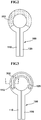
- FIG. 1 is an exploded perspective view illustrating a camera module thin film heater according to a first exemplary embodiment of the present invention.
- the camera module thin film heater (400) may include an electrode (100), a thin film heating body (200) and an insulation member (300).
- the electrode (100) may include a first electrode (110) and a second electrode (120), for example.
- the first electrode (110) may be formed to take a thin film shape when viewed from a plane, and the first electrode (110) may be manufactured with a material excellent in electric conductivity.
- the conductive material to be used as material for the first electrode (110) may be copper, copper alloy, aluminum and aluminum alloy.
- the first electrode (110) may be manufactured with a transparent electrode having an electric conductivity capable of generating a heat by self-resistant component of the first electrode (110) such as an ITO (Indium Thin Oxide), for example.
- ITO Indium Thin Oxide
- the first electrode (110) may be formed in a thin film shape.
- a portion of the first electrode (110) may be a straight part having a square shape and a curved part having a curved shape may be formed from a distal end of the straight part.
- the second electrode (120) may be in a state so arranged as to be spaced apart or insulated from the first electrode (110).
- the second electrode (120) may take a same shape as that of the first electrode (110), for example, and the second electrode (120) may be so arranged as to be symmetrical with the first electrode (110).
- the second electrode (120) may be formed to take a thin film shape, when viewed from a plane, and the second electrode (120) may be manufactured with a material excellent in electric conductivity.
- the second electrode (120) may be manufactured with the same material as that of the first electrode (110).
- first and second electrodes (110,120) are made of same material
- the first and second electrodes (110,120) may be made with materials having mutually different electric conductivity.
- the thin film heating body (200) may be manufactured with a thin film shape, where one end of the thin film heating body (200) may be electrically connected to the first electrode (110), and the other end of the thin film heating body (200) may be electrically connected to the second electrode (120).
- the thin film heating body (200) and the electrode (100) may be partially overlapped to be electrically connected.
- the thin film heating body (200) may take a partially opened ring shape when viewed from a plane surface, the thin film heating body (200), the first electrode (110) and the second electrode (120) may be mutually electrically connected to form a ring shape when viewed from a plane surface.
- the thin film heating body (200) may be electrically connected to the first and second electrodes (110, 120) to allow a power to be provided to the thin film heating body (200) through the first and second electrodes (110,120) whereby a heat can be generated from the thin film heating body (200).
- these three elements may be formed to take a circular-ring shape when viewed from a plane surface.
- the thin film heating body (200) may have an electric resistance-actively changing electric characteristic in response to a current temperature or a heating temperature of the thin film heating body (200).
- the thin film heating body (200) in the exemplary embodiment of the present invention may have an electric characteristic where an electric resistance quickly increases when a temperature increases differently from a resistance heating body like a nichrome wire, and the electric resistance conversely decreases when the temperature decreases.
- the thin film heating body (200) may include a PTC (Positive Temperature Coefficient) material, and may be manufactured in a shape of a semiconductor device.
- the thin film heating body (200) in the exemplary embodiment of the present invention may be formed with an opaque material.
- the thin film heating body (200) when a power is supplied to the thin film heating body (200) through the electrode (100), a heat is started to be generated from the thin film heating body (200) through self-resistance, and an electric resistance of the thin film heating body (200) also increases as the heating temperature of thin film heating body (200) increases.
- the thin film heating body (200), in which electric resistances actively change in response to temperatures as detailed above, can advantageously reach a target temperature within a short period of time without separate temperature sensors and temperature control units, and is not heated above a target temperature, and as a result, there is still another advantage of less risk of fire and a predetermined temperature being maintained at all times.
- the thin film heating body (200) which has various advantages as discussed above, can be applied to a lens of a camera module frequently generated with frost, freezing and dew condensation by outside air, and installed at a limited space where a temperature sensor is difficult to be directly mounted.
- the heating characteristics of the thin film heating body (200) in the exemplary embodiment of the present invention can be variably changed by changing contact conditions between the electrode (100) and the thin film heating body (200).
- FIGS. 2 to 6 are plan view and cross-sectional view illustrating various contact methods between an electrode and a thin film heating body.
- a distal end of one side of the thin film heating body (200) may be electrically connected to an end of the first electrode (110) of the electrode (100), and a distal end of the other side facing the distal end of one side of the thin film heating body (200) may be electrically connected to an end of the second electrode (120) of the electrode (100).
- a distance (gap) between the first and second electrodes (110, 120) in a connection structure between the thin film heating body (200) and the electrode (100) in FIG. 2 may be relatively lengthily formed in order to prevent short-circuit between the first and second electrodes (110, 120).
- an end of the first electrode (110) may be formed with a first width reducer (115) formed to be narrower than a width of the first electrode (110), and the first width reducer (115) may be extended toward the second electrode (120).
- the first width reducer (115) may be formed in a curved shape when viewed from a plane.
- An end of the second electrode (120) may be formed with a second width reducer (125) formed to be narrower than a width of the second electrode (120), and the second width reducer (125) may be extended toward the first electrode (110).
- the second width reducer (125) may be formed in a curved shape when viewed on a plane.
- the first width reducer (115) of the first electrode (110) and the second width reducer (125) of the second electrode (120) may be so arranged as to face each other when viewed on a plane, and a space may be formed between the first and second width reducers (115,125).
- the thin film heating body (200) may be electrically connected to the first and second width reducers (115,125), and the thin film heating body (200) may be curvedly formed.
- a length between the first and second width reducers (115, 125) in the connection structure between the thin film heating body (200) and the electrode (100) in FIGS. 3 and 4 may be formed to be relatively shorter than what is shown in FIG. 2 .
- an end of the first electrode (110) may be extended toward the second electrode (120) without decreased area, and an end of the second electrode (120) may be extended toward the first electrode (110) without decreased area, and the first and second electrodes (110, 120) may be so arranged as to be mutually overlapped.
- the thin film heating body (200) may be interposed between the first and second electrodes (110,120).
- a length between the first and second width reducers (115, 125) in the connection structure between the thin film heating body (200) and the electrode (100) in FIGS. 5 and 6 may be formed to be relatively shorter than what is shown in FIGS. 3 and 4 .
- an amount of heat generated from the thin film heating body (200) can be changed by variably changing the connection structure between the thin film heating body (200) and the electrode (100).
- the insulation member (300) may function to insulate the thin film heating body (200) and the electrode (100) from an outside conductor wrapping the electrode (100) and the thin film heating body (200) and to prevent the thin film heating body (200) and the electrode (100) from being damaged by a force applied from an external force.
- the insulation member (300) may include a base film (310) and a cover film (320), for example.
- the electrode (100) and the thin film heating body (200) electrically connected to the electrode (100) may be interposed between the base film (310) and cover film (320).
- the mutual connection between the base film (310) and the cover film (320) may allow insulating the electrode (100) and the thin film heating body (200) between the base film (310) and the cover film (320).
- the camera module thin film heater (400) illustrated in FIGS. 1 to 6 may be particularly adequate when a transparent heating film including the ITO (Indium Tin Oxide) material, which is a transparent electrode, is not formed at an upper surface of a bottom surface of the lens, which is a subject to be heated.
- ITO Indium Tin Oxide
- the cover film (320) illustrated in FIG. 1 may be formed with the transparent heating film and an opening exposing the first and second electrodes (110, 120) to electrically connect the first and second electrodes (110, 120) forming the electrode (100).
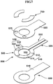
- FIG. 7 is an exploded perspective view illustrating a camera module thin film heater (800) according to another exemplary embodiment of the present invention.
- the camera module thin film heater (800) may include a first heating structure (525), a heating structure (500) including a second heating structure (550) and an insulation member (600).
- the camera module thin film heater in the exemplary embodiment of the present invention may further include a third electrode (700) additionally arranged to the insulation member (600).
- the first heating structure (525) may include a first electrode (510) and a first thin film heating body (520).
- the first electrode (510) and the first thin film heating body (520) may be electrically and mutually connected.
- the first electrode (510) may include a first electrode pattern (512) and a second electrode pattern (514), for example.
- the first electrode pattern (512) may be formed in a thin film shape when viewed from a plane, and the first electrode pattern (512) may be manufactured with a material excellent in electric conductivity.
- the conductive material to be used as material for the first electrode pattern (512) may be copper, copper alloy, aluminum and aluminum alloy, for example.
- the first electrode pattern (512) may be manufactured with an ITO (Indium Thin Oxide) material, a transparent electrode having an electric conductivity capable of generating a heat by self-resistant component of the first electrode pattern (512) such as an ITO (Indium Thin Oxide).
- the first electrode pattern (512) may include a straight part of rectangular shape, and a curved part extended in a curved shape from an end of the straight part.
- the second electrode pattern (514) may take a same shape and be made of same material as that of the first electrode pattern (512), and the second electrode pattern (514) may be arranged in a symmetrical shape with the first electrode pattern (512).
- first and second electrode patterns (512, 514) are illustrated and explained to be formed with the same conductive material in the exemplary embodiment of the present invention, the first and second electrode patterns (512, 514) may be manufactured with mutually different conductive materials.
- the first thin film heating body (520) may be formed in a shape of a thin film or coated with a thin film, and the first thin film heating body (520) may take a curved shape when viewed on a plane.
- the first thin film heating body (520) may have an electric characteristic in which an electric resistance quickly increases when a temperature increases, and the electric resistance conversely decreases when the temperature decreases.
- the first thin film heating body (520) may include a PTC (Positive Temperature Coefficient) material, and may be manufactured in a shape of a semiconductor device.
- the first thin film heating body (520) may be interposed between the first and second electrode patterns (512,514), where the first and second electrode patterns (512,514) and the first thin film heating body (200) may be electrically and mutually connected.
- the first heating structure (525) including the mutually electrically connected first electrode pattern (512), the first thin film heating body (520) and the second electrode pattern (514) may be formed in a semi-circular strip shape adequate for allowing the first heating body (525) to wrap a portion of round lens.
- the first heating structure (525) is formed with a semi-circular strip shape
- the first heating structure (525) may be changed in shape in response to the lens shape.
- the second heating structure (550) may include a second electrode (530) and a second thin film heating body (540).
- the second heating structure (550) in the exemplary embodiment of the present invention may be spaced apart from the first heating structure (525), the second heating structure (550) and the first heating structure (525) may be symmetrically arranged.
- the second electrode (530) of the second heating structure (550) and the second thin film heating body (540) may be electrically and mutually connected.
- the second electrode (530) may include a third electrode pattern (532) and a fourth electrode pattern (534).
- the third electrode pattern may take a shape of a thin film, when viewed on a plane, and the third electrode pattern (532) may be manufactured with a material excellent in electric conductivity.
- an electrically conductive material to be used for the third electrode pattern (532) may include a copper, a copper alloy and an aluminum alloy.
- the third electrode pattern (532) may be manufactured with an ITO (Indium Thin Oxide) which is a transparent electrode having an electric conductivity capable of generating a heat by self-resistant component.
- ITO Indium Thin Oxide
- a portion of the third electrode pattern (532) may be formed in a shape of a straight line and a portion of the third electrode pattern (532) may be curvedly shaped.
- the fourth electrode pattern (534) may be spaced apart from the third electrode pattern (532), and the fourth electrode pattern (534) may be manufactured with a same conductive material as that of the third electrode pattern (532).
- third and fourth electrode patterns (532, 534) are illustrated and explained to be formed with the same conductive material in the exemplary embodiment of the present invention, the third and fourth electrode patterns (532, 534) may be manufactured with mutually different conductive materials.
- the second thin film heating body (540) may be formed in a thin film shape, and the second thin film heating body (540) may be formed with a shape of a curved strip.
- the second thin film heating body (540) may have an electric characteristic in which an electric resistance quickly increases when a temperature increases, and the electric resistance conversely decreases when the temperature decreases.
- the second thin film heating body (540) may include a PTC (Positive Temperature Coefficient) material, and may be manufactured in a shape of a semiconductor device.
- the second thin film heating body (540) may be interposed between the third and fourth electrode patterns (532,534), where the third and fourth electrode patterns (532,534) and the second thin film heating body (540) may be electrically and mutually connected.
- the second heating structure (550) including the mutually electrically connected third electrode pattern (532), the second thin film heating body (540) and the fourth electrode pattern (534) may be formed in a semi-circular strip shape adequate for allowing wrapping remaining portions of lens module that are not wrapped by the first heating structure (525).
- the second heating structure (550) is formed with a semi-circular strip shape
- the second heating structure (550) may be changed in shape in response to the lens shape.
- the insulation member (600) may function to insulate the first heating structure (525) and the second heating body (550) from an outside conductor by wrapping the first heating structure (525) and the second heating body (550) and to prevent the first heating structure (525) and the second heating body (550) from being damaged by a force applied from an external force.
- the insulation member (600) may include a base film (610) and a cover film (620), for example.
- the first heating structure (525) and the second heating body (550) may be interposed between the base film (610) and cover film (620).
- the mutual connection between the base film (610) and the cover film (620) may allow insulating the first heating structure (525) and the second heating body (550) between the base film (610) and the cover film (620).
- the cover film (620) of the insulation member (600) in the exemplary embodiment of the present invention may be formed with an opening (625) exposing the second electrode pattern (514) and the fourth electrode pattern (534) respectively.
- the opening (625) may be formed to connect an outside conductor or an outside heater that electrically and mutually connects the first heating structure (525) and the second heating structure (550).
- the opening (625) is illustrated and explained to be formed at the cover film (620) in the exemplary embodiment of the present invention, the opening (625) may be formed at the first electrode pattern (512) and the second electrode pattern (514).
- the third electrode (700) may be disposed on the cover film (620) of the insulation member (600), and the third electrode (700) may be electrically connected to the second electrode pattern (514) and the fourth electrode pattern (534) through the opening (625).
- the third electrode (700) may be electrically connected to a transparent heating film disposed at an upper surface or a bottom surface of the lens mounted on the camera module.
- the power provided to the first electrode (510) in response to the third electrode (700) and the transparent heating film being electrically connected may pass the first thin film heating body (520), the transparent heating film, the second electrode (530) and second thin film insulator (540) to allow the transparent heating film, the first and second thin film heating bodies (520,540) to generate a heat.
- the thin film heating body (520) included in the first heating structure (525) of the camera module thin film heater (800) illustrated in FIG. 7 , and the second thin film heating body (540) included in the second heating structure (550) are such that resistance changes in active response to temperature, whereby a target temperature can be advantageously reached within a short period of time without separate temperature sensors and temperature control units, and heat is not reached above a target temperature, and as a result, there is another advantage of less risk of fire and a predetermined constant temperature scope being maintained at all times.
- the camera module thin film heater (800) which has various advantages as discussed above, can be easily mounted to a lens of a camera module frequently generated with frost, freezing and dew condensation by outside air, and installed at a limited space where a temperature sensor is difficult to be mounted.
- the heating characteristics of the heat-generating first and second thin film heating bodies (520, 540) in the exemplary embodiment of the present invention can be variably realized by changing contact conditions between the first and second electrode patterns (512, 514) and the first thin film heating body (520) and contact conditions between the third and fourth electrode patterns (532, 534) and the second thin film heating body (540).
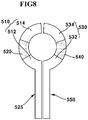
- FIGS. 8 to 10 are plan views illustrating various contact methods of first heating structure and second heating structure.
- a distal end of one side at the first thin film heating body (520) may be contacted in series to the first electrode pattern (512) of first electrode (510) and to the second electrode pattern (514) of the first electrode (510).
- a distance between the first and second electrode patterns (512, 514) in the connection structure between the first thin film heating body (520) and the first and second electrode patterns (512,514) may be relatively lengthily formed.
- an end of the first electrode pattern (512) at the first electrode (510) may be formed with a first width reducer (513) more narrowly formed in width than the first electrode pattern (512), and the first width reducer (513) may be extended toward the second electrode pattern (514).
- An end of the second electrode pattern (514) at the first electrode (510) may be formed with a second width reducer (515) more narrowly formed in width than the second electrode pattern (514), and the second width reducer (515) may be extended toward the first electrode pattern (512).
- the first thin film heating body (520) may be electrically connected to the first and second width reducers (513,515) respectively.
- An end of the third electrode pattern (532) at the second electrode (530) may be formed with a third width reducer (533) more narrowly formed in width than the third electrode pattern (532), and the third width reducer (532) may be extended toward the fourth electrode pattern (534).
- An end of the fourth electrode pattern (534) at the second electrode (530) may be formed with a fourth width reducer (535) more narrowly formed in width than the fourth electrode pattern (534), and the fourth width reducer (535) may be extended toward the third electrode pattern (532).
- the second thin film heating body (540) may be electrically connected to the third and fourth width reducers (533,535).
- a distance between the first and second width reducers (513, 515) and the third and fourth width reducers (533, 535) in the connection structure of FIG. 9 may be relatively shortly formed over what is shown in FIG. 8 .
- the first electrode pattern (512) of the first electrode (510) and the second electrode pattern (514) may be mutually overlapped, and the third electrode pattern (532) of the second electrode (530) and the fourth electrode pattern (535) may be mutually overlapped.
- the first thin film heating body (520) may be interposed between the mutually overlapped first electrode pattern (512) and the second electrode pattern (514), and a second thin film heating body (540) may be interposed between the mutually overlapped third electrode pattern (532) and the fourth electrode pattern (534).
- a distance between the first and second electrode patterns (512, 514) and the third and fourth electrode patterns (532, 534) in the connection structure of FIG. 10 may be relatively shortly formed over what is shown in FIG. 9 .
- An amount of heat generated from the first and second thin film heating bodies (520, 540) may be controlled by variably changing the connection structure as illustrated in FIGS. 8 , 9 and 10 .
- FIG. 11 is a cross-sectional view illustrating a camera module including a thin film heater according to still another exemplary embodiment of the present invention.
- the camera thin film heater illustrated in FIG. 11 has a substantially same structure as that of the camera module thin film heater (400) illustrated in FIGS. 1 to 6 .
- any recurrent and repeated explanation that is same in structure will be omitted, and same names and reference numerals will be provided to the same structures.
- a camera module (950) may include a camera module body (940) and a camera thin film heater (400).
- the camera module body (940) may include a body (910) formed with an accommodation space, an image sensor (920) disposed at an inside of the body (910) and a lens (930).
- the camera thin film heater (400) in the exemplary embodiment of the present invention may be interposed between the lens (930) and then body (910).
- the camera thin film heater (400) may include a thin film heating body (200) generating a heat by a power provided through the electrode (100), where the thin film heating body (200) has an electric characteristic in which resistances are changed in response to the heating temperature.
- the camera thin film heater (400) may directly contact the lens (200) to provide a heat to the lens (200), whereby frost, dew condensation and freezing are prevented from being formed.
- a portion of the electrode (100) electrically connected to the thin film heating body (200) in the camera thin film heater (400) may be extended to a bottom surface of the body (910) along a lateral surface of the body (910), and the electrode (100) may be provided with a power from outside.
- FIG. 12 is a cross-sectional view illustrating a camera module (1000) including a thin film heater according to still another exemplary embodiment of the present invention.
- the camera thin film heater illustrated in FIG. 12 has a substantially same structure as that of the camera module thin film heater (800) illustrated in FIGS. 7 to 10 .
- any recurrent and repeated explanation that is same in structure will be omitted, and same names and reference numerals will be provided to the same structures.
- the camera module (1000) may include a camera module body (940) and a camera thin film heater (800).
- the camera module body (940) may include a body (910) formed with an accommodation space, an image sensor (920) disposed at an inside of the body (910) and a lens (930).
- a transparent heating film (935) that is transparent and that generates a heat when a power is provided may be formed at a bottom surface of the lens (930) in the exemplary embodiment of the present invention.
- FIG. 12 has illustrated and explained that the transparent heating film (935) is formed at a bottom surface of the lens (930), the transparent heating film (930) may be formed at an upper surface of the lens (935), and when the transparent heating film (935) is formed at an upper surface of the lens (930), a portion of the transparent heating film (935) may be extended to a bottom surface of the lens (930).
- the camera thin film heater (800) in the exemplary embodiment of the present invention may be interposed between the lens (930) and then body (910).
- the camera thin film heater (800) may include a first heating structure (525) and a second heating structure (550), and a part of the power provided to the first heating structure (525) may be provided to the first heating structure (525), the transparent heating film (935) and the second heating structure (550), whereby the transparent heating film (935) can be heated.
- the transparent heating film (935) in the exemplary embodiment of the present invention may include an ITO (Indium Tin Oxide) material adequate to generating a heat in accordance with the transparent heating film (935) being transparent and being provided with a power.
- ITO Indium Tin Oxide
- the first thin film heating body (520) included in the first heating structure (525) and the second thin film heating body (550) included in the second heating structure (550) may be also heated in the course of the transparent heating film (935) being heated, and the first and second thin film heating bodies (520,540) may function as an auxiliary in heat-generation by the transparent heating film (935).
- the camera thin film heater (800) may multiply provide heat to the transparent heating film (935) directly formed on the lens (930) and to the first and second thin film heating bodies (520,540) to thereby prevent the lens (930) from being formed with frost, freezing and dew condensation.
- the present invention provides a camera module thin film heater and a camera module having the same that can prevent and avoid frost, condensation and freezing by reaching a target temperature of a lens within a short period of time, suppressing the generation of fire due to overheating even when operated in a high environment, and not including a temperature sensor and a temperature control unit, thereby greatly reducing the manufacturing cost.
- the present invention can be used as a vehicular camera module, an exterior CCTV and a monitoring camera installed on an outside of a vehicle where a temperature difference is great.
Landscapes
- Physics & Mathematics (AREA)
- General Physics & Mathematics (AREA)
- Engineering & Computer Science (AREA)
- Optics & Photonics (AREA)
- Aviation & Aerospace Engineering (AREA)
- Multimedia (AREA)
- Signal Processing (AREA)
- Surface Heating Bodies (AREA)
- Resistance Heating (AREA)
- Camera Bodies And Camera Details Or Accessories (AREA)
- Chemical & Material Sciences (AREA)
- Chemical Kinetics & Catalysis (AREA)
Priority Applications (2)
| Application Number | Priority Date | Filing Date | Title |
|---|---|---|---|
| EP25150455.1A EP4524639A3 (de) | 2015-09-15 | 2016-09-12 | Dünnschichtheizer für kameramodul und kameramodul damit |
| EP21175344.7A EP3913432B1 (de) | 2015-09-15 | 2016-09-12 | Dünnschichtheizer für kameramodul und kameramodul damit |
Applications Claiming Priority (2)
| Application Number | Priority Date | Filing Date | Title |
|---|---|---|---|
| KR1020150130091A KR102487620B1 (ko) | 2015-09-15 | 2015-09-15 | 카메라 모듈용 박막 히터 및 이를 갖는 카메라 모듈 |
| PCT/KR2016/010261 WO2017048014A1 (ko) | 2015-09-15 | 2016-09-12 | 카메라 모듈용 박막 히터 및 이를 갖는 카메라 모듈 |
Related Child Applications (3)
| Application Number | Title | Priority Date | Filing Date |
|---|---|---|---|
| EP21175344.7A Division-Into EP3913432B1 (de) | 2015-09-15 | 2016-09-12 | Dünnschichtheizer für kameramodul und kameramodul damit |
| EP21175344.7A Division EP3913432B1 (de) | 2015-09-15 | 2016-09-12 | Dünnschichtheizer für kameramodul und kameramodul damit |
| EP25150455.1A Division EP4524639A3 (de) | 2015-09-15 | 2016-09-12 | Dünnschichtheizer für kameramodul und kameramodul damit |
Publications (3)
| Publication Number | Publication Date |
|---|---|
| EP3352008A1 true EP3352008A1 (de) | 2018-07-25 |
| EP3352008A4 EP3352008A4 (de) | 2018-09-05 |
| EP3352008B1 EP3352008B1 (de) | 2021-06-30 |
Family
ID=58289532
Family Applications (3)
| Application Number | Title | Priority Date | Filing Date |
|---|---|---|---|
| EP25150455.1A Pending EP4524639A3 (de) | 2015-09-15 | 2016-09-12 | Dünnschichtheizer für kameramodul und kameramodul damit |
| EP16846835.3A Active EP3352008B1 (de) | 2015-09-15 | 2016-09-12 | Dünnschichtheizer für kameramodul und kameramodul damit |
| EP21175344.7A Active EP3913432B1 (de) | 2015-09-15 | 2016-09-12 | Dünnschichtheizer für kameramodul und kameramodul damit |
Family Applications Before (1)
| Application Number | Title | Priority Date | Filing Date |
|---|---|---|---|
| EP25150455.1A Pending EP4524639A3 (de) | 2015-09-15 | 2016-09-12 | Dünnschichtheizer für kameramodul und kameramodul damit |
Family Applications After (1)
| Application Number | Title | Priority Date | Filing Date |
|---|---|---|---|
| EP21175344.7A Active EP3913432B1 (de) | 2015-09-15 | 2016-09-12 | Dünnschichtheizer für kameramodul und kameramodul damit |
Country Status (5)
| Country | Link |
|---|---|
| US (1) | US11143864B2 (de) |
| EP (3) | EP4524639A3 (de) |
| KR (3) | KR102487620B1 (de) |
| CN (1) | CN108027548B (de) |
| WO (1) | WO2017048014A1 (de) |
Cited By (5)
| Publication number | Priority date | Publication date | Assignee | Title |
|---|---|---|---|---|
| KR20200113641A (ko) * | 2019-03-26 | 2020-10-07 | 엘지이노텍 주식회사 | 히팅 장치 및 카메라 모듈 |
| EP3826428A1 (de) * | 2019-11-22 | 2021-05-26 | Honeywell International Inc. | Fensterheizvorrichtung |
| WO2021148179A1 (de) * | 2020-01-22 | 2021-07-29 | Robert Bosch Gmbh | Kameramodul |
| JP2022527753A (ja) * | 2019-03-26 | 2022-06-06 | エルジー イノテック カンパニー リミテッド | ヒーティング装置及びカメラモジュール |
| EP4123357A1 (de) * | 2021-07-23 | 2023-01-25 | Ficosa Adas, S.L.U. | Linsenanordnung, kameramodul mit einer linsenanordnung für kraftfahrzeuge und herstellungsverfahren einer solchen linsenanordnung |
Families Citing this family (27)
| Publication number | Priority date | Publication date | Assignee | Title |
|---|---|---|---|---|
| KR102524129B1 (ko) | 2016-02-15 | 2023-04-21 | 엘지이노텍 주식회사 | 카메라 모듈용 히팅 장치 및 이를 갖는 카메라 모듈 |
| JP6723194B2 (ja) * | 2017-04-26 | 2020-07-15 | 株式会社東海理化電機製作所 | 撮像装置 |
| CN107181902A (zh) * | 2017-07-11 | 2017-09-19 | 信利光电股份有限公司 | 一种摄像头盖板及摄像头 |
| JP2019046786A (ja) * | 2017-09-04 | 2019-03-22 | 株式会社デンソー | ヒータ装置 |
| KR102123677B1 (ko) * | 2018-08-21 | 2020-06-17 | 엘지전자 주식회사 | 전기 히터 |
| JP7293969B2 (ja) * | 2018-10-25 | 2023-06-20 | 株式会社デンソー | ヒータ装置 |
| US11453366B2 (en) * | 2018-11-06 | 2022-09-27 | Motherson Innovations Company Limited | Heatable device for use with a vehicle-mounted image acquisition unit |
| KR102243382B1 (ko) * | 2018-11-30 | 2021-04-22 | 에이치엔티 일렉트로닉스(주) | 발열 기능이 구비된 카메라 모듈 및 그 제조방법 |
| KR102700062B1 (ko) | 2018-12-21 | 2024-08-29 | 엘지이노텍 주식회사 | 액체 렌즈를 포함하는 카메라 모듈 및 그의 제어 방법 |
| US12386142B2 (en) | 2019-05-31 | 2025-08-12 | Lg Innotek Co., Ltd. | Camera module |
| JP7339023B2 (ja) * | 2019-06-07 | 2023-09-05 | マクセル株式会社 | レンズユニットおよびカメラモジュール |
| WO2020253541A1 (zh) * | 2019-06-17 | 2020-12-24 | 宁波舜宇车载光学技术有限公司 | 光学装置及其应用 |
| JP2021012352A (ja) * | 2019-07-09 | 2021-02-04 | パナソニックi−PROセンシングソリューションズ株式会社 | 監視カメラおよびカバー |
| KR102296895B1 (ko) * | 2019-09-18 | 2021-09-01 | 주식회사 아이엠첨단소재 | 발열 디바이스 및 이를 이용하는 차량용 카메라 |
| CN111983766A (zh) * | 2019-12-31 | 2020-11-24 | 江西联创电子有限公司 | 光学镜头及成像模组 |
| US11927747B2 (en) | 2019-12-31 | 2024-03-12 | Jiangxi Lianchuang Electronic Co., Ltd. | Camera module, vehicle camera and monitoring system |
| JP7407007B2 (ja) * | 2020-02-07 | 2023-12-28 | 株式会社東海理化電機製作所 | 車両用撮像装置 |
| KR102742832B1 (ko) * | 2020-02-25 | 2024-12-13 | 리텔퓨즈 인코퍼레이티드 | 안정한 전력 및 자가 제한 거동을 갖는 pptc 히터 및 재료 |
| US11650391B2 (en) * | 2020-02-25 | 2023-05-16 | Littelfuse, Inc. | PPTC heater and material having stable power and self-limiting behavior |
| US20210400179A1 (en) * | 2020-06-18 | 2021-12-23 | Ford Global Technologies, Llc | Sensor system with cleaning and heating |
| SE547236C2 (en) * | 2020-06-30 | 2025-06-10 | Orlaco Products B V | Camera system with lens heater |
| JP7517884B2 (ja) * | 2020-07-15 | 2024-07-17 | ニデックインスツルメンツ株式会社 | レンズユニット |
| JP7449801B2 (ja) * | 2020-07-15 | 2024-03-14 | ニデックインスツルメンツ株式会社 | レンズユニット |
| KR102483614B1 (ko) * | 2020-09-01 | 2023-01-02 | 삼성전기주식회사 | 카메라 모듈 |
| EP4363920B1 (de) * | 2021-07-02 | 2026-05-06 | Teledyne FLIR Commercial Systems, Inc. | Beheizte kameras und zugehörige verfahren |
| JP2023023904A (ja) * | 2021-08-06 | 2023-02-16 | マクセル株式会社 | ヒータ、レンズユニット、カメラモジュール、車載システム、移動体およびヒータ組み込み方法 |
| WO2025009338A1 (ja) * | 2023-07-05 | 2025-01-09 | 東京コスモス電機株式会社 | 発熱装置および撮像装置 |
Family Cites Families (26)
| Publication number | Priority date | Publication date | Assignee | Title |
|---|---|---|---|---|
| US4309596A (en) * | 1980-06-24 | 1982-01-05 | Sunbeam Corporation | Flexible self-limiting heating cable |
| DE3144275C1 (de) * | 1981-11-07 | 1983-04-14 | Grundig E.M.V. Elektro-Mechanische Versuchsanstalt Max Grundig & Co KG, 8510 Fürth | "Kompakt-Fernsehkamera für Innenraum- oder Außenverwendung" |
| JPH0738788A (ja) | 1993-07-22 | 1995-02-07 | Sharp Corp | カメラ監視装置 |
| DE4436087C2 (de) * | 1994-10-10 | 2003-06-18 | Siedle & Soehne S | Heizvorrichtung für eine lichtdurchlässige Schutzscheibe eines Schutzgehäuses einer Kamera |
| DE29514364U1 (de) * | 1995-09-07 | 1996-01-18 | Hohe GmbH & Co. KG, 97903 Collenberg | Bildaufnahmemodul |
| JPH11231696A (ja) * | 1998-02-10 | 1999-08-27 | Canon Inc | 加熱体、加熱装置、及び画像形成装置 |
| JP2001066934A (ja) * | 1999-08-27 | 2001-03-16 | Canon Inc | 加熱装置及び画像形成装置 |
| US7480149B2 (en) * | 2004-08-18 | 2009-01-20 | Donnelly Corporation | Accessory module for vehicle |
| DE60333497D1 (de) * | 2003-05-22 | 2010-09-02 | Fico Mirrors Sa | Bilderfassungsmodul mit einer heizeinrichtung, mit der das umfeld eines kraftfahrzeugs überwacht wird |
| DE10340900A1 (de) * | 2003-09-02 | 2005-03-24 | Valeo Schalter Und Sensoren Gmbh | Kameramodul mit heizbarer Abdeckscheibe |
| KR200342920Y1 (ko) * | 2003-12-02 | 2004-02-19 | (주)동화이엔지 | 도전성 투명 발열막을 형성된 카메라 |
| JP4789572B2 (ja) * | 2005-10-11 | 2011-10-12 | シチズン電子株式会社 | 液晶レンズ装置 |
| KR20070018642A (ko) * | 2005-08-10 | 2007-02-14 | 엘지전자 주식회사 | 카메라 대물렌즈 윈도우의 습기제거 구조 및 장치 및 방법 |
| KR200424379Y1 (ko) * | 2006-06-07 | 2006-08-22 | 김종만 | 투명 히터막을 구비한 투시창 |
| US20100084161A1 (en) * | 2008-10-08 | 2010-04-08 | Robert A. Neal | Conductive film and process for making same |
| DE102008063849A1 (de) * | 2008-12-19 | 2010-06-24 | Tesa Se | Beheiztes Flächenelement und Verfahren zu seiner Befestigung |
| KR20100094838A (ko) * | 2009-02-19 | 2010-08-27 | (주)씨프로 | 습기방지용 카메라 |
| WO2010108041A1 (en) * | 2009-03-18 | 2010-09-23 | Artificial Muscle, Inc. | Wafer level optical system |
| JP5344346B2 (ja) * | 2009-12-02 | 2013-11-20 | 山本光学株式会社 | 防曇レンズ類及び眼用保護具 |
| KR20110068442A (ko) * | 2009-12-16 | 2011-06-22 | 주식회사 오카스 | 카메라 윈도우 성에방지용 히터와 그 구동시스템 |
| CN103202093B (zh) * | 2010-11-08 | 2016-01-20 | 松下知识产权经营株式会社 | 面状发热体及其制造方法 |
| TWM408051U (en) * | 2011-01-04 | 2011-07-21 | Topview Optronics Corp | Defogging and defrosting device for camera protection lens |
| CN104620671B (zh) * | 2012-06-26 | 2016-05-18 | Iee国际电子工程股份公司 | 不具有电子功率控制的ptc加热装置 |
| JP6071366B2 (ja) | 2012-09-19 | 2017-02-01 | キヤノン株式会社 | ヒータ及びこのヒータを搭載する像加熱装置 |
| KR101462983B1 (ko) * | 2013-09-27 | 2014-11-18 | 한국생산기술연구원 | 투명 면상 발열체가 형성된 cctv 카메라 |
| CN204169862U (zh) * | 2014-10-22 | 2015-02-25 | 苏州新业电子有限公司 | 口腔摄像头安装箱 |
-
2015
- 2015-09-15 KR KR1020150130091A patent/KR102487620B1/ko active Active
-
2016
- 2016-09-12 WO PCT/KR2016/010261 patent/WO2017048014A1/ko not_active Ceased
- 2016-09-12 US US15/760,528 patent/US11143864B2/en active Active
- 2016-09-12 EP EP25150455.1A patent/EP4524639A3/de active Pending
- 2016-09-12 EP EP16846835.3A patent/EP3352008B1/de active Active
- 2016-09-12 CN CN201680053695.7A patent/CN108027548B/zh active Active
- 2016-09-12 EP EP21175344.7A patent/EP3913432B1/de active Active
-
2023
- 2023-01-06 KR KR1020230002433A patent/KR102679724B1/ko active Active
-
2024
- 2024-06-25 KR KR1020240083059A patent/KR20240104081A/ko active Pending
Cited By (12)
| Publication number | Priority date | Publication date | Assignee | Title |
|---|---|---|---|---|
| KR20200113641A (ko) * | 2019-03-26 | 2020-10-07 | 엘지이노텍 주식회사 | 히팅 장치 및 카메라 모듈 |
| JP2022527753A (ja) * | 2019-03-26 | 2022-06-06 | エルジー イノテック カンパニー リミテッド | ヒーティング装置及びカメラモジュール |
| EP3951494A4 (de) * | 2019-03-26 | 2022-12-28 | LG Innotek Co., Ltd. | Erwärmungsvorrichtung und kameramodul |
| US12422643B2 (en) | 2019-03-26 | 2025-09-23 | Lg Innotek Co., Ltd. | Heating device and camera module |
| EP3826428A1 (de) * | 2019-11-22 | 2021-05-26 | Honeywell International Inc. | Fensterheizvorrichtung |
| US12010766B2 (en) | 2019-11-22 | 2024-06-11 | Honeywell International Inc. | Window heating apparatus |
| WO2021148179A1 (de) * | 2020-01-22 | 2021-07-29 | Robert Bosch Gmbh | Kameramodul |
| CN115004078A (zh) * | 2020-01-22 | 2022-09-02 | 罗伯特·博世有限公司 | 摄像机模块 |
| KR20220126769A (ko) * | 2020-01-22 | 2022-09-16 | 로베르트 보쉬 게엠베하 | 카메라 모듈 |
| KR102882895B1 (ko) | 2020-01-22 | 2025-11-07 | 로베르트 보쉬 게엠베하 | 카메라 모듈 |
| EP4123357A1 (de) * | 2021-07-23 | 2023-01-25 | Ficosa Adas, S.L.U. | Linsenanordnung, kameramodul mit einer linsenanordnung für kraftfahrzeuge und herstellungsverfahren einer solchen linsenanordnung |
| US12591134B2 (en) | 2021-07-23 | 2026-03-31 | Ficosa Adas, S.L.U. | Lens assembly, camera module having a lens assembly for motor vehicles, and a method for making lens assembly |
Also Published As
| Publication number | Publication date |
|---|---|
| CN108027548A (zh) | 2018-05-11 |
| KR20240104081A (ko) | 2024-07-04 |
| EP3352008B1 (de) | 2021-06-30 |
| EP4524639A2 (de) | 2025-03-19 |
| KR102487620B1 (ko) | 2023-01-12 |
| US11143864B2 (en) | 2021-10-12 |
| KR20230010268A (ko) | 2023-01-18 |
| KR20170032585A (ko) | 2017-03-23 |
| US20190041630A1 (en) | 2019-02-07 |
| CN108027548B (zh) | 2021-11-26 |
| EP3913432A3 (de) | 2022-03-23 |
| EP4524639A3 (de) | 2025-11-19 |
| KR102679724B1 (ko) | 2024-07-01 |
| WO2017048014A1 (ko) | 2017-03-23 |
| EP3913432A2 (de) | 2021-11-24 |
| EP3352008A4 (de) | 2018-09-05 |
| EP3913432B1 (de) | 2025-01-15 |
Similar Documents
| Publication | Publication Date | Title |
|---|---|---|
| US11143864B2 (en) | Camera module thin film heater | |
| CN106575842B (zh) | 具有温度传感器的插拔连接件 | |
| CN107534255B (zh) | 具有温度监测装置的连接器部件 | |
| US7666033B1 (en) | Power plug with over temperature and over current protection | |
| CN105679476B (zh) | 压敏电阻器 | |
| TWI528407B (zh) | 阻止電流及電壓異常狀態的複合保護裝置 | |
| CN101630674B (zh) | 包括电阻和熔线元件的电路保护装置 | |
| US20150364286A1 (en) | Complex protection device | |
| TWI545606B (zh) | 複合保護裝置 | |
| US20150303011A1 (en) | Complex protection device for blocking abnormal state of current and voltage | |
| KR102174814B1 (ko) | 내장된 제어 유닛을 가지는 전압 공급원에 평판체를 연결하기 위한 조립체 | |
| US20150249333A1 (en) | Complex protection device of blocking the abnormal state of current and voltage | |
| JP6383013B2 (ja) | 電子デバイス | |
| TWI528406B (zh) | 阻止電流及電壓異常狀態的複合保護裝置 | |
| JP7829221B2 (ja) | 面状発熱体 | |
| CN113906527A (zh) | 器件和器件的应用 | |
| TWI547967B (zh) | 複合保護裝置 | |
| JP3219722U (ja) | ヒータ | |
| JP2024046973A (ja) | ヒータユニット及びその応用品 | |
| WO2023276464A1 (ja) | 面状発熱体、光学装置、および面状発熱体の製造方法 | |
| JP2015215955A (ja) | ヒータ | |
| TW201546854A (zh) | 阻止電流及電壓異常狀態的複合保護裝置 | |
| TH66081B (th) | ชิ้นส่วนตรวจจับอินฟาเรดแบบไพโรอิเล็กทริกและเซ็นเซอร์อินฟาเรดที่ใช้ชิ้นส่วนนั้น | |
| JP2011213136A (ja) | 車載用ヒータ |
Legal Events
| Date | Code | Title | Description |
|---|---|---|---|
| STAA | Information on the status of an ep patent application or granted ep patent |
Free format text: STATUS: THE INTERNATIONAL PUBLICATION HAS BEEN MADE |
|
| PUAI | Public reference made under article 153(3) epc to a published international application that has entered the european phase |
Free format text: ORIGINAL CODE: 0009012 |
|
| STAA | Information on the status of an ep patent application or granted ep patent |
Free format text: STATUS: REQUEST FOR EXAMINATION WAS MADE |
|
| 17P | Request for examination filed |
Effective date: 20180330 |
|
| AK | Designated contracting states |
Kind code of ref document: A1 Designated state(s): AL AT BE BG CH CY CZ DE DK EE ES FI FR GB GR HR HU IE IS IT LI LT LU LV MC MK MT NL NO PL PT RO RS SE SI SK SM TR |
|
| AX | Request for extension of the european patent |
Extension state: BA ME |
|
| A4 | Supplementary search report drawn up and despatched |
Effective date: 20180807 |
|
| RIC1 | Information provided on ipc code assigned before grant |
Ipc: G02B 27/00 20060101ALI20180801BHEP Ipc: H05B 3/12 20060101ALN20180801BHEP Ipc: G03B 17/55 20060101AFI20180801BHEP |
|
| DAV | Request for validation of the european patent (deleted) | ||
| DAX | Request for extension of the european patent (deleted) | ||
| GRAP | Despatch of communication of intention to grant a patent |
Free format text: ORIGINAL CODE: EPIDOSNIGR1 |
|
| RIC1 | Information provided on ipc code assigned before grant |
Ipc: G03B 17/55 20060101AFI20201214BHEP Ipc: G02B 27/00 20060101ALI20201214BHEP Ipc: H05B 3/12 20060101ALN20201214BHEP |
|
| STAA | Information on the status of an ep patent application or granted ep patent |
Free format text: STATUS: GRANT OF PATENT IS INTENDED |
|
| INTG | Intention to grant announced |
Effective date: 20210121 |
|
| GRAS | Grant fee paid |
Free format text: ORIGINAL CODE: EPIDOSNIGR3 |
|
| GRAA | (expected) grant |
Free format text: ORIGINAL CODE: 0009210 |
|
| STAA | Information on the status of an ep patent application or granted ep patent |
Free format text: STATUS: THE PATENT HAS BEEN GRANTED |
|
| AK | Designated contracting states |
Kind code of ref document: B1 Designated state(s): AL AT BE BG CH CY CZ DE DK EE ES FI FR GB GR HR HU IE IS IT LI LT LU LV MC MK MT NL NO PL PT RO RS SE SI SK SM TR |
|
| REG | Reference to a national code |
Ref country code: CH Ref legal event code: EP |
|
| REG | Reference to a national code |
Ref country code: AT Ref legal event code: REF Ref document number: 1406882 Country of ref document: AT Kind code of ref document: T Effective date: 20210715 |
|
| REG | Reference to a national code |
Ref country code: DE Ref legal event code: R096 Ref document number: 602016060107 Country of ref document: DE |
|
| REG | Reference to a national code |
Ref country code: IE Ref legal event code: FG4D |
|
| REG | Reference to a national code |
Ref country code: NL Ref legal event code: FP |
|
| REG | Reference to a national code |
Ref country code: LT Ref legal event code: MG9D |
|
| PG25 | Lapsed in a contracting state [announced via postgrant information from national office to epo] |
Ref country code: FI Free format text: LAPSE BECAUSE OF FAILURE TO SUBMIT A TRANSLATION OF THE DESCRIPTION OR TO PAY THE FEE WITHIN THE PRESCRIBED TIME-LIMIT Effective date: 20210630 Ref country code: HR Free format text: LAPSE BECAUSE OF FAILURE TO SUBMIT A TRANSLATION OF THE DESCRIPTION OR TO PAY THE FEE WITHIN THE PRESCRIBED TIME-LIMIT Effective date: 20210630 Ref country code: BG Free format text: LAPSE BECAUSE OF FAILURE TO SUBMIT A TRANSLATION OF THE DESCRIPTION OR TO PAY THE FEE WITHIN THE PRESCRIBED TIME-LIMIT Effective date: 20210930 |
|
| REG | Reference to a national code |
Ref country code: AT Ref legal event code: MK05 Ref document number: 1406882 Country of ref document: AT Kind code of ref document: T Effective date: 20210630 |
|
| PG25 | Lapsed in a contracting state [announced via postgrant information from national office to epo] |
Ref country code: LV Free format text: LAPSE BECAUSE OF FAILURE TO SUBMIT A TRANSLATION OF THE DESCRIPTION OR TO PAY THE FEE WITHIN THE PRESCRIBED TIME-LIMIT Effective date: 20210630 Ref country code: GR Free format text: LAPSE BECAUSE OF FAILURE TO SUBMIT A TRANSLATION OF THE DESCRIPTION OR TO PAY THE FEE WITHIN THE PRESCRIBED TIME-LIMIT Effective date: 20211001 Ref country code: NO Free format text: LAPSE BECAUSE OF FAILURE TO SUBMIT A TRANSLATION OF THE DESCRIPTION OR TO PAY THE FEE WITHIN THE PRESCRIBED TIME-LIMIT Effective date: 20210930 Ref country code: SE Free format text: LAPSE BECAUSE OF FAILURE TO SUBMIT A TRANSLATION OF THE DESCRIPTION OR TO PAY THE FEE WITHIN THE PRESCRIBED TIME-LIMIT Effective date: 20210630 Ref country code: RS Free format text: LAPSE BECAUSE OF FAILURE TO SUBMIT A TRANSLATION OF THE DESCRIPTION OR TO PAY THE FEE WITHIN THE PRESCRIBED TIME-LIMIT Effective date: 20210630 |
|
| PG25 | Lapsed in a contracting state [announced via postgrant information from national office to epo] |
Ref country code: SM Free format text: LAPSE BECAUSE OF FAILURE TO SUBMIT A TRANSLATION OF THE DESCRIPTION OR TO PAY THE FEE WITHIN THE PRESCRIBED TIME-LIMIT Effective date: 20210630 Ref country code: SK Free format text: LAPSE BECAUSE OF FAILURE TO SUBMIT A TRANSLATION OF THE DESCRIPTION OR TO PAY THE FEE WITHIN THE PRESCRIBED TIME-LIMIT Effective date: 20210630 Ref country code: RO Free format text: LAPSE BECAUSE OF FAILURE TO SUBMIT A TRANSLATION OF THE DESCRIPTION OR TO PAY THE FEE WITHIN THE PRESCRIBED TIME-LIMIT Effective date: 20210630 Ref country code: PT Free format text: LAPSE BECAUSE OF FAILURE TO SUBMIT A TRANSLATION OF THE DESCRIPTION OR TO PAY THE FEE WITHIN THE PRESCRIBED TIME-LIMIT Effective date: 20211102 Ref country code: ES Free format text: LAPSE BECAUSE OF FAILURE TO SUBMIT A TRANSLATION OF THE DESCRIPTION OR TO PAY THE FEE WITHIN THE PRESCRIBED TIME-LIMIT Effective date: 20210630 Ref country code: EE Free format text: LAPSE BECAUSE OF FAILURE TO SUBMIT A TRANSLATION OF THE DESCRIPTION OR TO PAY THE FEE WITHIN THE PRESCRIBED TIME-LIMIT Effective date: 20210630 Ref country code: CZ Free format text: LAPSE BECAUSE OF FAILURE TO SUBMIT A TRANSLATION OF THE DESCRIPTION OR TO PAY THE FEE WITHIN THE PRESCRIBED TIME-LIMIT Effective date: 20210630 Ref country code: AT Free format text: LAPSE BECAUSE OF FAILURE TO SUBMIT A TRANSLATION OF THE DESCRIPTION OR TO PAY THE FEE WITHIN THE PRESCRIBED TIME-LIMIT Effective date: 20210630 |
|
| PG25 | Lapsed in a contracting state [announced via postgrant information from national office to epo] |
Ref country code: PL Free format text: LAPSE BECAUSE OF FAILURE TO SUBMIT A TRANSLATION OF THE DESCRIPTION OR TO PAY THE FEE WITHIN THE PRESCRIBED TIME-LIMIT Effective date: 20210630 |
|
| REG | Reference to a national code |
Ref country code: DE Ref legal event code: R097 Ref document number: 602016060107 Country of ref document: DE |
|
| PG25 | Lapsed in a contracting state [announced via postgrant information from national office to epo] |
Ref country code: DK Free format text: LAPSE BECAUSE OF FAILURE TO SUBMIT A TRANSLATION OF THE DESCRIPTION OR TO PAY THE FEE WITHIN THE PRESCRIBED TIME-LIMIT Effective date: 20210630 |
|
| REG | Reference to a national code |
Ref country code: CH Ref legal event code: PL |
|
| PLBE | No opposition filed within time limit |
Free format text: ORIGINAL CODE: 0009261 |
|
| STAA | Information on the status of an ep patent application or granted ep patent |
Free format text: STATUS: NO OPPOSITION FILED WITHIN TIME LIMIT |
|
| REG | Reference to a national code |
Ref country code: BE Ref legal event code: MM Effective date: 20210930 |
|
| PG25 | Lapsed in a contracting state [announced via postgrant information from national office to epo] |
Ref country code: MC Free format text: LAPSE BECAUSE OF FAILURE TO SUBMIT A TRANSLATION OF THE DESCRIPTION OR TO PAY THE FEE WITHIN THE PRESCRIBED TIME-LIMIT Effective date: 20210630 Ref country code: AL Free format text: LAPSE BECAUSE OF FAILURE TO SUBMIT A TRANSLATION OF THE DESCRIPTION OR TO PAY THE FEE WITHIN THE PRESCRIBED TIME-LIMIT Effective date: 20210630 |
|
| 26N | No opposition filed |
Effective date: 20220331 |
|
| PG25 | Lapsed in a contracting state [announced via postgrant information from national office to epo] |
Ref country code: LU Free format text: LAPSE BECAUSE OF NON-PAYMENT OF DUE FEES Effective date: 20210912 Ref country code: IT Free format text: LAPSE BECAUSE OF FAILURE TO SUBMIT A TRANSLATION OF THE DESCRIPTION OR TO PAY THE FEE WITHIN THE PRESCRIBED TIME-LIMIT Effective date: 20210630 Ref country code: IE Free format text: LAPSE BECAUSE OF NON-PAYMENT OF DUE FEES Effective date: 20210912 Ref country code: BE Free format text: LAPSE BECAUSE OF NON-PAYMENT OF DUE FEES Effective date: 20210930 |
|
| PG25 | Lapsed in a contracting state [announced via postgrant information from national office to epo] |
Ref country code: LI Free format text: LAPSE BECAUSE OF NON-PAYMENT OF DUE FEES Effective date: 20210930 Ref country code: CH Free format text: LAPSE BECAUSE OF NON-PAYMENT OF DUE FEES Effective date: 20210930 |
|
| PG25 | Lapsed in a contracting state [announced via postgrant information from national office to epo] |
Ref country code: LT Free format text: LAPSE BECAUSE OF FAILURE TO SUBMIT A TRANSLATION OF THE DESCRIPTION OR TO PAY THE FEE WITHIN THE PRESCRIBED TIME-LIMIT Effective date: 20210630 |
|
| PG25 | Lapsed in a contracting state [announced via postgrant information from national office to epo] |
Ref country code: HU Free format text: LAPSE BECAUSE OF FAILURE TO SUBMIT A TRANSLATION OF THE DESCRIPTION OR TO PAY THE FEE WITHIN THE PRESCRIBED TIME-LIMIT; INVALID AB INITIO Effective date: 20160912 |
|
| PG25 | Lapsed in a contracting state [announced via postgrant information from national office to epo] |
Ref country code: CY Free format text: LAPSE BECAUSE OF FAILURE TO SUBMIT A TRANSLATION OF THE DESCRIPTION OR TO PAY THE FEE WITHIN THE PRESCRIBED TIME-LIMIT Effective date: 20210630 |
|
| PG25 | Lapsed in a contracting state [announced via postgrant information from national office to epo] |
Ref country code: MK Free format text: LAPSE BECAUSE OF FAILURE TO SUBMIT A TRANSLATION OF THE DESCRIPTION OR TO PAY THE FEE WITHIN THE PRESCRIBED TIME-LIMIT Effective date: 20210630 |
|
| PG25 | Lapsed in a contracting state [announced via postgrant information from national office to epo] |
Ref country code: TR Free format text: LAPSE BECAUSE OF FAILURE TO SUBMIT A TRANSLATION OF THE DESCRIPTION OR TO PAY THE FEE WITHIN THE PRESCRIBED TIME-LIMIT Effective date: 20210630 |
|
| PG25 | Lapsed in a contracting state [announced via postgrant information from national office to epo] |
Ref country code: MT Free format text: LAPSE BECAUSE OF FAILURE TO SUBMIT A TRANSLATION OF THE DESCRIPTION OR TO PAY THE FEE WITHIN THE PRESCRIBED TIME-LIMIT Effective date: 20210630 |
|
| PGFP | Annual fee paid to national office [announced via postgrant information from national office to epo] |
Ref country code: NL Payment date: 20250821 Year of fee payment: 10 |
|
| PGFP | Annual fee paid to national office [announced via postgrant information from national office to epo] |
Ref country code: DE Payment date: 20250820 Year of fee payment: 10 |
|
| PGFP | Annual fee paid to national office [announced via postgrant information from national office to epo] |
Ref country code: GB Payment date: 20250820 Year of fee payment: 10 |
|
| PGFP | Annual fee paid to national office [announced via postgrant information from national office to epo] |
Ref country code: FR Payment date: 20250821 Year of fee payment: 10 |