EP3352216A1 - Dissipateur thermique type stratifié - Google Patents
Dissipateur thermique type stratifié Download PDFInfo
- Publication number
- EP3352216A1 EP3352216A1 EP16846696.9A EP16846696A EP3352216A1 EP 3352216 A1 EP3352216 A1 EP 3352216A1 EP 16846696 A EP16846696 A EP 16846696A EP 3352216 A1 EP3352216 A1 EP 3352216A1
- Authority
- EP
- European Patent Office
- Prior art keywords
- plate
- cooled
- heat sink
- type heat
- refrigerant
- Prior art date
- Legal status (The legal status is an assumption and is not a legal conclusion. Google has not performed a legal analysis and makes no representation as to the accuracy of the status listed.)
- Granted
Links
Images


Classifications
-
- F—MECHANICAL ENGINEERING; LIGHTING; HEATING; WEAPONS; BLASTING
- F28—HEAT EXCHANGE IN GENERAL
- F28F—DETAILS OF HEAT-EXCHANGE AND HEAT-TRANSFER APPARATUS, OF GENERAL APPLICATION
- F28F13/00—Arrangements for modifying heat-transfer, e.g. increasing, decreasing
- F28F13/003—Arrangements for modifying heat-transfer, e.g. increasing, decreasing by using permeable mass, perforated or porous materials
-
- F—MECHANICAL ENGINEERING; LIGHTING; HEATING; WEAPONS; BLASTING
- F28—HEAT EXCHANGE IN GENERAL
- F28D—HEAT-EXCHANGE APPARATUS, NOT PROVIDED FOR IN ANOTHER SUBCLASS, IN WHICH THE HEAT-EXCHANGE MEDIA DO NOT COME INTO DIRECT CONTACT
- F28D1/00—Heat-exchange apparatus having stationary conduit assemblies for one heat-exchange medium only, the media being in contact with different sides of the conduit wall, in which the other heat-exchange medium is a large body of fluid, e.g. domestic or motor car radiators
- F28D1/02—Heat-exchange apparatus having stationary conduit assemblies for one heat-exchange medium only, the media being in contact with different sides of the conduit wall, in which the other heat-exchange medium is a large body of fluid, e.g. domestic or motor car radiators with heat-exchange conduits immersed in the body of fluid
- F28D1/03—Heat-exchange apparatus having stationary conduit assemblies for one heat-exchange medium only, the media being in contact with different sides of the conduit wall, in which the other heat-exchange medium is a large body of fluid, e.g. domestic or motor car radiators with heat-exchange conduits immersed in the body of fluid with plate-like or laminated conduits
- F28D1/0308—Heat-exchange apparatus having stationary conduit assemblies for one heat-exchange medium only, the media being in contact with different sides of the conduit wall, in which the other heat-exchange medium is a large body of fluid, e.g. domestic or motor car radiators with heat-exchange conduits immersed in the body of fluid with plate-like or laminated conduits the conduits being formed by paired plates touching each other
- F28D1/0325—Heat-exchange apparatus having stationary conduit assemblies for one heat-exchange medium only, the media being in contact with different sides of the conduit wall, in which the other heat-exchange medium is a large body of fluid, e.g. domestic or motor car radiators with heat-exchange conduits immersed in the body of fluid with plate-like or laminated conduits the conduits being formed by paired plates touching each other the plates having lateral openings therein for circulation of the heat-exchange medium from one conduit to another
-
- F—MECHANICAL ENGINEERING; LIGHTING; HEATING; WEAPONS; BLASTING
- F28—HEAT EXCHANGE IN GENERAL
- F28F—DETAILS OF HEAT-EXCHANGE AND HEAT-TRANSFER APPARATUS, OF GENERAL APPLICATION
- F28F13/00—Arrangements for modifying heat-transfer, e.g. increasing, decreasing
- F28F13/06—Arrangements for modifying heat-transfer, e.g. increasing, decreasing by affecting the pattern of flow of the heat-exchange media
- F28F13/08—Arrangements for modifying heat-transfer, e.g. increasing, decreasing by affecting the pattern of flow of the heat-exchange media by varying the cross-section of the flow channels
-
- F—MECHANICAL ENGINEERING; LIGHTING; HEATING; WEAPONS; BLASTING
- F28—HEAT EXCHANGE IN GENERAL
- F28F—DETAILS OF HEAT-EXCHANGE AND HEAT-TRANSFER APPARATUS, OF GENERAL APPLICATION
- F28F3/00—Plate-like or laminated elements; Assemblies of plate-like or laminated elements
- F28F3/02—Elements or assemblies thereof with means for increasing heat-transfer area, e.g. with fins, with recesses, with corrugations
- F28F3/04—Elements or assemblies thereof with means for increasing heat-transfer area, e.g. with fins, with recesses, with corrugations the means being integral with the element
-
- F—MECHANICAL ENGINEERING; LIGHTING; HEATING; WEAPONS; BLASTING
- F28—HEAT EXCHANGE IN GENERAL
- F28F—DETAILS OF HEAT-EXCHANGE AND HEAT-TRANSFER APPARATUS, OF GENERAL APPLICATION
- F28F3/00—Plate-like or laminated elements; Assemblies of plate-like or laminated elements
- F28F3/08—Elements constructed for building-up into stacks, e.g. capable of being taken apart for cleaning
- F28F3/086—Elements constructed for building-up into stacks, e.g. capable of being taken apart for cleaning having one or more openings therein forming tubular heat-exchange passages
-
- H—ELECTRICITY
- H05—ELECTRIC TECHNIQUES NOT OTHERWISE PROVIDED FOR
- H05K—PRINTED CIRCUITS; CASINGS OR CONSTRUCTIONAL DETAILS OF ELECTRIC APPARATUS; MANUFACTURE OF ASSEMBLAGES OF ELECTRICAL COMPONENTS
- H05K7/00—Constructional details common to different types of electric apparatus
- H05K7/20—Modifications to facilitate cooling, ventilating, or heating
- H05K7/2089—Modifications to facilitate cooling, ventilating, or heating for power electronics, e.g. for inverters for controlling motor
- H05K7/20927—Liquid coolant without phase change
-
- H—ELECTRICITY
- H10—SEMICONDUCTOR DEVICES; ELECTRIC SOLID-STATE DEVICES NOT OTHERWISE PROVIDED FOR
- H10W—GENERIC PACKAGES, INTERCONNECTIONS, CONNECTORS OR OTHER CONSTRUCTIONAL DETAILS OF DEVICES COVERED BY CLASS H10
- H10W40/00—Arrangements for thermal protection or thermal control
- H10W40/40—Arrangements for thermal protection or thermal control involving heat exchange by flowing fluids
- H10W40/47—Arrangements for thermal protection or thermal control involving heat exchange by flowing fluids by flowing liquids, e.g. forced water cooling
-
- F—MECHANICAL ENGINEERING; LIGHTING; HEATING; WEAPONS; BLASTING
- F28—HEAT EXCHANGE IN GENERAL
- F28D—HEAT-EXCHANGE APPARATUS, NOT PROVIDED FOR IN ANOTHER SUBCLASS, IN WHICH THE HEAT-EXCHANGE MEDIA DO NOT COME INTO DIRECT CONTACT
- F28D21/00—Heat-exchange apparatus not covered by any of the groups F28D1/00 - F28D20/00
- F28D2021/0019—Other heat exchangers for particular applications; Heat exchange systems not otherwise provided for
- F28D2021/0028—Other heat exchangers for particular applications; Heat exchange systems not otherwise provided for for cooling heat generating elements, e.g. for cooling electronic components or electric devices
- F28D2021/0029—Heat sinks
Definitions
- the present invention relates to a compact laminated type heat sink that cools an object to be cooled (as an example, a semiconductor element such as an inverter, and the like).
- Patent Literature 1 a laminated type heat sink is proposed.
- This is fabricated, as illustrated in Fig. 11 , by press-molding a metal flat plate to form a pair of manifolds (not illustrated), and drilling a plurality of slits 2 between these. Between each of the slits 2, a fin part is formed by long and thin longitudinal ribs 3 that are in parallel to each other and transverse ribs 4 that link between the adjacent longitudinal ribs 3 to constitute a flat plate. Further, lamination is performed so that, in the fin part of each plate, the longitudinal ribs 3 thereof are matched with each other and the transverse ribs 4 are shifted in the width direction of the plate from each other.
- an end lid 7 On both vertical sides of the laminated body of plates, an end lid 7 is arranged, a semiconductor element such as an inverter is mounted on the end lid 7, and a refrigerant is circulated into the fin part of each plate via the manifold.
- a semiconductor element such as an inverter
- ranges in which heat exchange is performed actively are respective ranges formed in a reverse trapezoidal shape downward and shown by sand particles. That is, in ranges described by reverse trapezoids in a net mark, heat exchange is active. Further, the range is illustrated in a sand particle-like state.
- portions illustrated by trapezoids rising from a lower side toward an upper side in which the sand particle-like state is absent are portions in which heat exchange is less likely to be performed.
- the present invention aims at feeding predominantly a refrigerant to portions in which heat exchange is actively performed to totally accelerate heat exchange.
- the present invention described in Claim 1 is a laminated type heat sink, in which:
- the present invention described in Claim 2 is the laminated type heat sink according to Claim 1, wherein:
- the present invention described in Claim 3 is the laminated type heat sink according to Claim 1, wherein:
- the present invention described in Claim 4 is the laminated type heat sink according to Claim 1, wherein:
- the present invention described in Claim 5 is a laminated type heat sink, in which:
- the present invention described in Claim 6 is the laminated type heat sink according to Claim 5, wherein:
- the present invention described in Claim 7 is the laminated type heat sink according to Claim 5, wherein:
- the present invention described in Claim 8 is the laminated type heat sink according to Claim 5, wherein:
- the laminated type heat sink of the present invention is provided with a circulation blocking means 9 for a refrigerant so that, in positons sufficiently apart in a lamination direction from an object 8 to be cooled, a circulation path of a refrigerant in a fin part of respective plates 6 decreases in a lower portion of the respective plates 6.
- the refrigerant can be circulated in a larger quantity into plates nearer to the object 8 to be cooled to accelerate heat exchange.
- the laminated type heat sink described in Claim 2 has, in the above configuration, a second plate 6a with the plurality of slits 2 formed in a projection position of the object 8 to be cooled and other parts formed into a blank part 11 without a slit.
- a third plate 6b thereof includes a blockade wall 14 rising orthogonally to a plane in a part on a side orthogonal to a refrigerant flow direction, and a position of the side part that is a side part of the each plate 6 apart, when the object 8 to be cooled is projected to each plate 6, from the projected body is blockaded with the blockade wall 14.
- one third plate 6b blockades a side portion of other plate 6 and, without circulating a fluid into a portion of the plate 6 that does not actively contribute to cooling, the refrigerant can be circulated into other portions to accelerate heat exchange.
- the laminated type heat sink described in Claim 4 is characterized, in Claim 1, by having a barrier body 15 that is a separate member from the plate 6, and blockading a side part of the respective plates 6 with an L letter-like part 15a of the barrier body 15.
- a core 18 including a laminated body of a plate 21 is internally mounted in a casing 19. Consequently, a laminated type heat sink that has a simple structure and is easily manufactured and assembled can be provided.
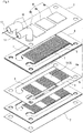
- Fig. 1 illustrates an exploded perspective view of a heat sink of the present invention
- Fig. 2 illustrates an assembled state of the same
- Fig. 3 illustrates a longitudinal cross-sectional view of the assembled state.
- a core is formed by a laminated body of a plurality of plates 6 and second plates 6a, and an end lid 7 is arranged to both upper and lower ends of the core. Then, each of plates is integrally brazed to each other.
- the plate 6 lying on the end lid 7 side is the plate of a conventional type illustrated in Fig. 11 , in which a pair of manifold parts 1 in parallel to each other are formed on both sides in a width direction of a metal flat plate, and, between the respective manifold parts 1, a fin part 5 is arranged.
- the fin part 5 is formed as the conventional one illustrated in Fig. 11 , a plurality of slits 2 is arranged in parallel, longitudinal ribs 3 are arranged between the respective slits 2, and transverse ribs 4 link between the respective longitudinal ribs 3. Then, each of the slits 2 is matched with each other and laminated, and each of the transverse ribs 4 is arranged in a different position for each of adjacent plates.
- the second plate 6a arranged in a position apart from the end lid 7 lies on a lower side in a lamination direction, as illustrated in Fig. 1 . That is, it is the second plate 6a arranged farther relative to the end lid 7 having an object 8 to be cooled, and the fin part 5 and a blank part 11 are arranged alternately between the manifold parts 1.
- three objects 8 to be cooled, that is, 8a to 8c are joined on the end lid 7, but the number of objects to be cooled is not limited to this.
- a pair of inlet/outlet pipes 16 are arranged to the end lid 7 on the upper side, each of which is communicated with the pair of manifold parts 1 of each of the plates 6 and second plates 6a.
- the objects 8a to 8c to be cooled are arranged to the end lid 7 on the upper side.
- a refrigerant 17 is fed to each manifold part 1 of each of the plates 6 and second plates 6a, which winds in up/down directions through the slit 2 in the fin part 5 thereof and circulates from one manifold part 1 to the other manifold part 1.
- the refrigerant 17 circulates evenly through the slit of each of the fin parts 5 in the plate 6 lying near the end lid 7 on the upper side.
- the refrigerant 17 does not circulate into the blank part 11 (which constitutes a circulation blocking means 9 of the present invention), and circulates only into a part of the fin part 5 of the second plate 6a.
- the refrigerant 17 is fed intensively to the fin part 5. Consequently, in regions in which heat exchange is less in Fig. 6 (portions rising in a trapezoid-like shape from a lower side), the refrigerant is fed only to the fin part 5 and not fed to the blank part 11. Consequently, the refrigerant is fed to the fin part 5 more effectively to accelerate heat exchange as a whole.
- the objects 8a to 8c to be cooled are arranged only to the end lid 7 on the upper side, but an object to be cooled can also be arranged to the end lid 7 on the lower side together with the end lid 7 on the upper side.
- the plurality of second plates 6a is arranged at a middle height, and, on both sides thereof, a laminated body of the ordinary plate 6 is arranged.
- Fig. 4 illustrates a core part of a heat sink in second Example of the present invention, and a third plate 6b used for the core part.
- the core part includes a laminated body in which only a plate lying at the lowest end in a lamination direction is the third plate 6b and all the other plates are the conventional plate 6.
- the blockade walls 14 of the third plate 6b lying at the lowest end blockade, respectively, both sides of the plate 6 lying on a lower side as in Fig. 4(B) . Then, the refrigerant fed to each of the manifold parts 1 is blocked to circulate into the inside of the fin by the blockade wall 14.
- an object to be cooled is arranged to a not illustrated end lid lying at the highest end.
- the blockade walls 14 in vertically reversed directions are mounted, respectively, on not illustrated two third plates 6b lying in the middle.
- Fig. 5 illustrates third Example of the present invention.
- a core is formed by a laminated body of the ordinary plate 6, and, to each manifold part 1 thereof, a barrier body 15 illustrated in Fig. 5(A) is arranged.
- the barrier body 15 has a width equal to the width of the manifold part 1, and a length equal to the base arranged in a trapezoid-like shape from a lower side toward an upper side in Fig. 6 . Then the barrier body 15 is arranged to a position of the upward trapezoid-like shape in Fig. 6 .
- the barrier body 15 forms the circulation blocking means 9 of the present invention. Meanwhile, in Fig.
- the example is also an example in which an object to be cooled is arranged to a not illustrated upper end lid, and the same can also be arranged to a lower end lid.
- the barrier bodies 15 in vertically reversed directions are arranged on a plate part lying in the middle. Then, a part of the fin part 5 of each of the plates 6 is partially blockaded by each L letter-like part 15a.
- Fig. 7 illustrates a comparison between heat resistance of a conventional type heat sink and heat resistance of the heat sink of the present invention (arrangement of the object 8 to be cooled in Fig. 2 ) .
- the heat resistance in the present invention is smaller than that in the conventional type.
- the heat resistance here is a value that shows difficulty of temperature transmission, and means temperature rise per unit time and per quantity of heat generation with a unit of °C/W.
- Fig. 7 white in the bar graph shows the heat resistance of the conventional laminated type heat sink in which respective plates are identical.
- the heat resistance of the heat sink of the present invention is shown by slash marks in each bar graph.
- the heat resistance of the conventional article is 0.194 °C/W.
- the heat resistance in the present invention is 0.193 °C/W.
- Fig. 8 illustrates an exploded perspective view of fourth Example of the present invention.
- the different point of this from the invention in Fig. 1 is that a frame part of the periphery of each of the plates 6 in Fig. 1 is removed.
- the core 18 is formed by a laminated body of plates 21, and the core 18 is mounted inside a casing 19.
- a pair of dish-like plates are sealed with a flange part of periphery and the pair of inlet/outlet pipes 16 are projected from an end part.
- the blank part 11 exists in two positions in a second plate 21a without a frame, and the blank part 11 forms the circulation blocking means 9.
- Fig. 9 illustrates an exploded perspective view of fifth Example of the present invention.
- the different point of this from the invention in Fig. 4 is that a frame part of the periphery of each of the plates 6 in Fig. 4 is removed.
- Fig. 10 illustrates an exploded perspective view of sixth Example of the present invention.
- the different point of this from the invention in Fig. 5 is that a frame part of the periphery of each of the plates 6 in Fig. 5 is removed.
- the present invention can be used for cooling a semiconductor such as an inverter.
Landscapes
- Engineering & Computer Science (AREA)
- Physics & Mathematics (AREA)
- Thermal Sciences (AREA)
- Mechanical Engineering (AREA)
- General Engineering & Computer Science (AREA)
- Microelectronics & Electronic Packaging (AREA)
- Chemical & Material Sciences (AREA)
- Dispersion Chemistry (AREA)
- Cooling Or The Like Of Semiconductors Or Solid State Devices (AREA)
- Cooling Or The Like Of Electrical Apparatus (AREA)
Applications Claiming Priority (2)
| Application Number | Priority Date | Filing Date | Title |
|---|---|---|---|
| JP2015184706 | 2015-09-18 | ||
| PCT/JP2016/078132 WO2017047825A1 (fr) | 2015-09-18 | 2016-09-14 | Dissipateur thermique type stratifié |
Publications (3)
| Publication Number | Publication Date |
|---|---|
| EP3352216A1 true EP3352216A1 (fr) | 2018-07-25 |
| EP3352216A4 EP3352216A4 (fr) | 2019-05-08 |
| EP3352216B1 EP3352216B1 (fr) | 2021-11-10 |
Family
ID=58289403
Family Applications (1)
| Application Number | Title | Priority Date | Filing Date |
|---|---|---|---|
| EP16846696.9A Active EP3352216B1 (fr) | 2015-09-18 | 2016-09-14 | Dissipateur thermique type stratifié |
Country Status (5)
| Country | Link |
|---|---|
| US (1) | US10655922B2 (fr) |
| EP (1) | EP3352216B1 (fr) |
| JP (1) | JP6746594B2 (fr) |
| CN (1) | CN107924898B (fr) |
| WO (1) | WO2017047825A1 (fr) |
Cited By (4)
| Publication number | Priority date | Publication date | Assignee | Title |
|---|---|---|---|---|
| WO2022135907A1 (fr) * | 2020-12-26 | 2022-06-30 | International Business Machines Corporation | Transition de plaque froide à chute de pression réduite |
| CN114698333A (zh) * | 2020-12-26 | 2022-07-01 | 国际商业机器公司 | 具有均匀气室流的冷却板 |
| WO2022229031A1 (fr) * | 2021-04-25 | 2022-11-03 | Danfoss Silicon Power Gmbh | Refroidisseur de composant électronique |
| FR3154799A1 (fr) * | 2023-10-26 | 2025-05-02 | Valeo Systemes Thermiques | Dispositif de régulation thermique |
Families Citing this family (14)
| Publication number | Priority date | Publication date | Assignee | Title |
|---|---|---|---|---|
| US10837718B2 (en) * | 2015-09-18 | 2020-11-17 | T.Rad Co., Ltd. | Laminated core type heat sink |
| US10766097B2 (en) * | 2017-04-13 | 2020-09-08 | Raytheon Company | Integration of ultrasonic additive manufactured thermal structures in brazements |
| JP6951786B2 (ja) | 2017-08-29 | 2021-10-20 | 株式会社Welcon | ヒートシンク |
| US10462941B2 (en) | 2017-11-06 | 2019-10-29 | Caterpillar Inc. | Heat sink assembly |
| JP6663899B2 (ja) * | 2017-11-29 | 2020-03-13 | 本田技研工業株式会社 | 冷却装置 |
| JP7015197B2 (ja) * | 2018-03-26 | 2022-02-02 | 新光電気工業株式会社 | ループ型ヒートパイプ及びその製造方法 |
| CN110543069A (zh) * | 2018-05-28 | 2019-12-06 | 中强光电股份有限公司 | 液冷式散热器 |
| US11740027B2 (en) * | 2019-04-12 | 2023-08-29 | T.Rad Co., Ltd. | Stacked plate heat exchanger |
| FR3100671A1 (fr) * | 2019-09-06 | 2021-03-12 | Valeo Siemens Eautomotive France Sas | Couvercle en plastique de fermeture d’un circuit de refroidissement à fluide, pour un équipement électrique |
| CN111473670A (zh) * | 2020-04-09 | 2020-07-31 | 浙江嘉熙科技有限公司 | 热超导传热板及散热器 |
| DE102020209125A1 (de) * | 2020-07-21 | 2022-01-27 | Mahle International Gmbh | Wärmeübertrager zum Kühlen einer Induktionsladeeinrichtung sowie Induktionsladeeinrichtung |
| JP7730240B2 (ja) * | 2020-12-26 | 2025-08-27 | インターナショナル・ビジネス・マシーンズ・コーポレーション | 冷却板装置、冷却板装置を製造する方法および冷却板装置の有効体積を通る流れの均一性を向上させる方法 |
| US11832423B2 (en) * | 2021-03-23 | 2023-11-28 | Baidu Usa Llc | Liquid cooling unit for peripheral devices |
| US12096594B2 (en) * | 2021-09-23 | 2024-09-17 | The Esab Group Inc. | Fluidic routing structures for liquid cooling of power modules of power supplies |
Family Cites Families (29)
| Publication number | Priority date | Publication date | Assignee | Title |
|---|---|---|---|---|
| US4397234A (en) * | 1981-12-30 | 1983-08-09 | International Business Machines Corporation | Electromagnetic print hammer coil assembly |
| US5125451A (en) * | 1991-04-02 | 1992-06-30 | Microunity Systems Engineering, Inc. | Heat exchanger for solid-state electronic devices |
| US6678182B2 (en) * | 2000-11-07 | 2004-01-13 | United Defense Lp | Electrical bus with associated porous metal heat sink and method of manufacturing same |
| US7883670B2 (en) * | 2002-02-14 | 2011-02-08 | Battelle Memorial Institute | Methods of making devices by stacking sheets and processes of conducting unit operations using such devices |
| US6989134B2 (en) * | 2002-11-27 | 2006-01-24 | Velocys Inc. | Microchannel apparatus, methods of making microchannel apparatus, and processes of conducting unit operations |
| US6994245B2 (en) * | 2003-10-17 | 2006-02-07 | James M. Pinchot | Micro-reactor fabrication |
| FR2861894B1 (fr) * | 2003-10-31 | 2008-01-18 | Valeo Equip Electr Moteur | Dispositif de refroidissement d'une electronique de puissance |
| US7017655B2 (en) * | 2003-12-18 | 2006-03-28 | Modine Manufacturing Co. | Forced fluid heat sink |
| US20050189342A1 (en) * | 2004-02-23 | 2005-09-01 | Samer Kabbani | Miniature fluid-cooled heat sink with integral heater |
| US7247030B2 (en) * | 2004-04-05 | 2007-07-24 | Tyco Electronics Corporation | Bonded three dimensional laminate structure |
| AU2006226744B2 (en) * | 2005-03-23 | 2012-02-23 | Velocys, Inc. | Surface features in microprocess technology |
| EP1890802A2 (fr) * | 2005-05-25 | 2008-02-27 | Velocys, Inc. | Support destine a etre utilise dans le traitement a l'aide de microcanaux |
| JP4881583B2 (ja) * | 2005-06-27 | 2012-02-22 | 株式会社豊田自動織機 | パワーモジュール用ヒートシンク |
| CN100584169C (zh) * | 2006-04-21 | 2010-01-20 | 富准精密工业(深圳)有限公司 | 液冷散热装置 |
| JP2008171840A (ja) * | 2007-01-05 | 2008-07-24 | T Rad Co Ltd | 液冷ヒートシンクおよびその設計方法 |
| US20090165996A1 (en) * | 2007-12-26 | 2009-07-02 | Lynch Thomas W | Reticulated heat dissipation with coolant |
| US20110226448A1 (en) * | 2008-08-08 | 2011-09-22 | Mikros Manufacturing, Inc. | Heat exchanger having winding channels |
| US8474516B2 (en) * | 2008-08-08 | 2013-07-02 | Mikros Manufacturing, Inc. | Heat exchanger having winding micro-channels |
| US9599407B2 (en) * | 2009-07-29 | 2017-03-21 | Tokitae Llc | System and structure for heating or sterilizing a liquid stream |
| KR101200930B1 (ko) * | 2010-05-04 | 2012-11-13 | 한국과학기술연구원 | 마이크로-매크로 채널 반응기 |
| JP5485472B2 (ja) * | 2011-04-15 | 2014-05-07 | コリア インスティテュート オブ エナジー リサーチ | 微細流路加熱器を用いた炭化水素改質装置 |
| JP6006480B2 (ja) * | 2011-07-29 | 2016-10-12 | 株式会社ティラド | 液冷ヒートシンク |
| US20140231055A1 (en) * | 2011-09-06 | 2014-08-21 | Vacuum Process Engineering, Inc. | Heat Exchanger Produced from Laminar Elements |
| JP6064362B2 (ja) | 2012-05-09 | 2017-01-25 | Tdk株式会社 | 積層コンデンサ |
| JP6026808B2 (ja) * | 2012-08-03 | 2016-11-16 | 株式会社ティラド | 積層型ヒートシンクのコア |
| JP6164304B2 (ja) * | 2013-11-28 | 2017-07-19 | 富士電機株式会社 | 半導体モジュール用冷却器の製造方法、半導体モジュール用冷却器、半導体モジュール及び電気駆動車両 |
| FR3024214A3 (fr) * | 2014-07-23 | 2016-01-29 | Muller & Cie Soc | Appareil de stockage thermoelectrique saisonnier |
| US9721870B2 (en) * | 2014-12-05 | 2017-08-01 | International Business Machines Corporation | Cooling structure for electronic boards |
| US10847441B2 (en) * | 2017-03-16 | 2020-11-24 | Mitsubishi Electric Corporation | Cooling system |
-
2016
- 2016-09-14 EP EP16846696.9A patent/EP3352216B1/fr active Active
- 2016-09-14 JP JP2017540530A patent/JP6746594B2/ja active Active
- 2016-09-14 US US15/754,505 patent/US10655922B2/en active Active
- 2016-09-14 CN CN201680048097.0A patent/CN107924898B/zh active Active
- 2016-09-14 WO PCT/JP2016/078132 patent/WO2017047825A1/fr not_active Ceased
Cited By (7)
| Publication number | Priority date | Publication date | Assignee | Title |
|---|---|---|---|---|
| WO2022135907A1 (fr) * | 2020-12-26 | 2022-06-30 | International Business Machines Corporation | Transition de plaque froide à chute de pression réduite |
| CN114698333A (zh) * | 2020-12-26 | 2022-07-01 | 国际商业机器公司 | 具有均匀气室流的冷却板 |
| US11698233B2 (en) | 2020-12-26 | 2023-07-11 | International Business Machines Corporation | Reduced pressure drop cold plate transition |
| US12004322B2 (en) | 2020-12-26 | 2024-06-04 | International Business Machines Corporation | Cold plate with uniform plenum flow |
| US12158314B2 (en) | 2020-12-26 | 2024-12-03 | International Business Machines Corporation | Reduced pressure drop cold plate transition |
| WO2022229031A1 (fr) * | 2021-04-25 | 2022-11-03 | Danfoss Silicon Power Gmbh | Refroidisseur de composant électronique |
| FR3154799A1 (fr) * | 2023-10-26 | 2025-05-02 | Valeo Systemes Thermiques | Dispositif de régulation thermique |
Also Published As
| Publication number | Publication date |
|---|---|
| CN107924898A (zh) | 2018-04-17 |
| JP6746594B2 (ja) | 2020-08-26 |
| EP3352216A4 (fr) | 2019-05-08 |
| US10655922B2 (en) | 2020-05-19 |
| CN107924898B (zh) | 2020-10-27 |
| WO2017047825A1 (fr) | 2017-03-23 |
| US20180245862A1 (en) | 2018-08-30 |
| EP3352216B1 (fr) | 2021-11-10 |
| JPWO2017047825A1 (ja) | 2018-07-05 |
Similar Documents
| Publication | Publication Date | Title |
|---|---|---|
| EP3352216A1 (fr) | Dissipateur thermique type stratifié | |
| US20140014308A1 (en) | Heat Sink and Electronic Device and Heat Exchanger Applying the Same | |
| JP5901343B2 (ja) | 冷却器及び冷却装置 | |
| JP5983565B2 (ja) | 冷却器 | |
| US9888612B2 (en) | Heat exchanger for power-electronic components | |
| JP6358872B2 (ja) | 発熱素子用沸騰冷却器 | |
| US10224263B2 (en) | Heat exchanger | |
| EP3352215B1 (fr) | Dissipateur thermique type à noyau stratifié | |
| JP6256295B2 (ja) | 熱交換器 | |
| JP6738226B2 (ja) | 冷却装置 | |
| JP2010114174A (ja) | ヒートシンク用コア構造 | |
| JP6026772B2 (ja) | ヒートシンク | |
| CN105164488B (zh) | 气液分离型板状热交换器 | |
| JP6578964B2 (ja) | 積層型熱交換器 | |
| JP2010040757A (ja) | 電子部品冷却器 | |
| EP3187809A1 (fr) | Refroidisseur par évaporation à guidage d'air intégré et son procédé de fabrication | |
| US20100147501A1 (en) | Curled manifold for evaporator | |
| JP2013235967A (ja) | 積層型熱交換器 | |
| CN102563980A (zh) | 热交换器 | |
| JP5901416B2 (ja) | 熱交換器用フィンおよびそれを用いたヒートシンク、熱交換器用フィンの製造方法 | |
| JP6297463B2 (ja) | 積層型熱交換器 | |
| KR102069804B1 (ko) | 열교환기 및 이를 구비한 열교환장치 | |
| EP2819279B1 (fr) | Systeme de refroidissement | |
| EP3686535B1 (fr) | Condensateur | |
| JP2013130300A (ja) | 積層型熱交換器 |
Legal Events
| Date | Code | Title | Description |
|---|---|---|---|
| STAA | Information on the status of an ep patent application or granted ep patent |
Free format text: STATUS: THE INTERNATIONAL PUBLICATION HAS BEEN MADE |
|
| PUAI | Public reference made under article 153(3) epc to a published international application that has entered the european phase |
Free format text: ORIGINAL CODE: 0009012 |
|
| STAA | Information on the status of an ep patent application or granted ep patent |
Free format text: STATUS: REQUEST FOR EXAMINATION WAS MADE |
|
| 17P | Request for examination filed |
Effective date: 20180214 |
|
| AK | Designated contracting states |
Kind code of ref document: A1 Designated state(s): AL AT BE BG CH CY CZ DE DK EE ES FI FR GB GR HR HU IE IS IT LI LT LU LV MC MK MT NL NO PL PT RO RS SE SI SK SM TR |
|
| AX | Request for extension of the european patent |
Extension state: BA ME |
|
| DAV | Request for validation of the european patent (deleted) | ||
| DAX | Request for extension of the european patent (deleted) | ||
| A4 | Supplementary search report drawn up and despatched |
Effective date: 20190410 |
|
| RIC1 | Information provided on ipc code assigned before grant |
Ipc: H01L 23/473 20060101AFI20190404BHEP Ipc: H05K 7/20 20060101ALI20190404BHEP Ipc: F28F 3/08 20060101ALI20190404BHEP Ipc: F28F 13/00 20060101ALI20190404BHEP |
|
| RIC1 | Information provided on ipc code assigned before grant |
Ipc: H01L 23/473 20060101AFI20210324BHEP Ipc: F28F 3/08 20060101ALI20210324BHEP Ipc: F28F 13/00 20060101ALI20210324BHEP Ipc: H05K 7/20 20060101ALI20210324BHEP Ipc: F28F 3/04 20060101ALI20210324BHEP Ipc: F28F 13/08 20060101ALI20210324BHEP Ipc: F28D 1/03 20060101ALI20210324BHEP Ipc: F28D 21/00 20060101ALI20210324BHEP |
|
| GRAP | Despatch of communication of intention to grant a patent |
Free format text: ORIGINAL CODE: EPIDOSNIGR1 |
|
| STAA | Information on the status of an ep patent application or granted ep patent |
Free format text: STATUS: GRANT OF PATENT IS INTENDED |
|
| INTG | Intention to grant announced |
Effective date: 20210525 |
|
| GRAJ | Information related to disapproval of communication of intention to grant by the applicant or resumption of examination proceedings by the epo deleted |
Free format text: ORIGINAL CODE: EPIDOSDIGR1 |
|
| STAA | Information on the status of an ep patent application or granted ep patent |
Free format text: STATUS: REQUEST FOR EXAMINATION WAS MADE |
|
| GRAP | Despatch of communication of intention to grant a patent |
Free format text: ORIGINAL CODE: EPIDOSNIGR1 |
|
| STAA | Information on the status of an ep patent application or granted ep patent |
Free format text: STATUS: GRANT OF PATENT IS INTENDED |
|
| INTC | Intention to grant announced (deleted) | ||
| INTG | Intention to grant announced |
Effective date: 20210728 |
|
| GRAS | Grant fee paid |
Free format text: ORIGINAL CODE: EPIDOSNIGR3 |
|
| GRAA | (expected) grant |
Free format text: ORIGINAL CODE: 0009210 |
|
| STAA | Information on the status of an ep patent application or granted ep patent |
Free format text: STATUS: THE PATENT HAS BEEN GRANTED |
|
| AK | Designated contracting states |
Kind code of ref document: B1 Designated state(s): AL AT BE BG CH CY CZ DE DK EE ES FI FR GB GR HR HU IE IS IT LI LT LU LV MC MK MT NL NO PL PT RO RS SE SI SK SM TR |
|
| REG | Reference to a national code |
Ref country code: GB Ref legal event code: FG4D |
|
| REG | Reference to a national code |
Ref country code: AT Ref legal event code: REF Ref document number: 1446865 Country of ref document: AT Kind code of ref document: T Effective date: 20211115 Ref country code: CH Ref legal event code: EP |
|
| REG | Reference to a national code |
Ref country code: DE Ref legal event code: R096 Ref document number: 602016066141 Country of ref document: DE |
|
| REG | Reference to a national code |
Ref country code: IE Ref legal event code: FG4D |
|
| REG | Reference to a national code |
Ref country code: LT Ref legal event code: MG9D |
|
| REG | Reference to a national code |
Ref country code: NL Ref legal event code: MP Effective date: 20211110 |
|
| REG | Reference to a national code |
Ref country code: AT Ref legal event code: MK05 Ref document number: 1446865 Country of ref document: AT Kind code of ref document: T Effective date: 20211110 |
|
| PG25 | Lapsed in a contracting state [announced via postgrant information from national office to epo] |
Ref country code: RS Free format text: LAPSE BECAUSE OF FAILURE TO SUBMIT A TRANSLATION OF THE DESCRIPTION OR TO PAY THE FEE WITHIN THE PRESCRIBED TIME-LIMIT Effective date: 20211110 Ref country code: LT Free format text: LAPSE BECAUSE OF FAILURE TO SUBMIT A TRANSLATION OF THE DESCRIPTION OR TO PAY THE FEE WITHIN THE PRESCRIBED TIME-LIMIT Effective date: 20211110 Ref country code: FI Free format text: LAPSE BECAUSE OF FAILURE TO SUBMIT A TRANSLATION OF THE DESCRIPTION OR TO PAY THE FEE WITHIN THE PRESCRIBED TIME-LIMIT Effective date: 20211110 Ref country code: BG Free format text: LAPSE BECAUSE OF FAILURE TO SUBMIT A TRANSLATION OF THE DESCRIPTION OR TO PAY THE FEE WITHIN THE PRESCRIBED TIME-LIMIT Effective date: 20220210 Ref country code: AT Free format text: LAPSE BECAUSE OF FAILURE TO SUBMIT A TRANSLATION OF THE DESCRIPTION OR TO PAY THE FEE WITHIN THE PRESCRIBED TIME-LIMIT Effective date: 20211110 |
|
| PG25 | Lapsed in a contracting state [announced via postgrant information from national office to epo] |
Ref country code: IS Free format text: LAPSE BECAUSE OF FAILURE TO SUBMIT A TRANSLATION OF THE DESCRIPTION OR TO PAY THE FEE WITHIN THE PRESCRIBED TIME-LIMIT Effective date: 20220310 Ref country code: SE Free format text: LAPSE BECAUSE OF FAILURE TO SUBMIT A TRANSLATION OF THE DESCRIPTION OR TO PAY THE FEE WITHIN THE PRESCRIBED TIME-LIMIT Effective date: 20211110 Ref country code: PT Free format text: LAPSE BECAUSE OF FAILURE TO SUBMIT A TRANSLATION OF THE DESCRIPTION OR TO PAY THE FEE WITHIN THE PRESCRIBED TIME-LIMIT Effective date: 20220310 Ref country code: PL Free format text: LAPSE BECAUSE OF FAILURE TO SUBMIT A TRANSLATION OF THE DESCRIPTION OR TO PAY THE FEE WITHIN THE PRESCRIBED TIME-LIMIT Effective date: 20211110 Ref country code: NO Free format text: LAPSE BECAUSE OF FAILURE TO SUBMIT A TRANSLATION OF THE DESCRIPTION OR TO PAY THE FEE WITHIN THE PRESCRIBED TIME-LIMIT Effective date: 20220210 Ref country code: NL Free format text: LAPSE BECAUSE OF FAILURE TO SUBMIT A TRANSLATION OF THE DESCRIPTION OR TO PAY THE FEE WITHIN THE PRESCRIBED TIME-LIMIT Effective date: 20211110 Ref country code: LV Free format text: LAPSE BECAUSE OF FAILURE TO SUBMIT A TRANSLATION OF THE DESCRIPTION OR TO PAY THE FEE WITHIN THE PRESCRIBED TIME-LIMIT Effective date: 20211110 Ref country code: HR Free format text: LAPSE BECAUSE OF FAILURE TO SUBMIT A TRANSLATION OF THE DESCRIPTION OR TO PAY THE FEE WITHIN THE PRESCRIBED TIME-LIMIT Effective date: 20211110 Ref country code: GR Free format text: LAPSE BECAUSE OF FAILURE TO SUBMIT A TRANSLATION OF THE DESCRIPTION OR TO PAY THE FEE WITHIN THE PRESCRIBED TIME-LIMIT Effective date: 20220211 Ref country code: ES Free format text: LAPSE BECAUSE OF FAILURE TO SUBMIT A TRANSLATION OF THE DESCRIPTION OR TO PAY THE FEE WITHIN THE PRESCRIBED TIME-LIMIT Effective date: 20211110 |
|
| PG25 | Lapsed in a contracting state [announced via postgrant information from national office to epo] |
Ref country code: SM Free format text: LAPSE BECAUSE OF FAILURE TO SUBMIT A TRANSLATION OF THE DESCRIPTION OR TO PAY THE FEE WITHIN THE PRESCRIBED TIME-LIMIT Effective date: 20211110 Ref country code: SK Free format text: LAPSE BECAUSE OF FAILURE TO SUBMIT A TRANSLATION OF THE DESCRIPTION OR TO PAY THE FEE WITHIN THE PRESCRIBED TIME-LIMIT Effective date: 20211110 Ref country code: RO Free format text: LAPSE BECAUSE OF FAILURE TO SUBMIT A TRANSLATION OF THE DESCRIPTION OR TO PAY THE FEE WITHIN THE PRESCRIBED TIME-LIMIT Effective date: 20211110 Ref country code: EE Free format text: LAPSE BECAUSE OF FAILURE TO SUBMIT A TRANSLATION OF THE DESCRIPTION OR TO PAY THE FEE WITHIN THE PRESCRIBED TIME-LIMIT Effective date: 20211110 Ref country code: DK Free format text: LAPSE BECAUSE OF FAILURE TO SUBMIT A TRANSLATION OF THE DESCRIPTION OR TO PAY THE FEE WITHIN THE PRESCRIBED TIME-LIMIT Effective date: 20211110 Ref country code: CZ Free format text: LAPSE BECAUSE OF FAILURE TO SUBMIT A TRANSLATION OF THE DESCRIPTION OR TO PAY THE FEE WITHIN THE PRESCRIBED TIME-LIMIT Effective date: 20211110 |
|
| REG | Reference to a national code |
Ref country code: DE Ref legal event code: R097 Ref document number: 602016066141 Country of ref document: DE |
|
| PLBE | No opposition filed within time limit |
Free format text: ORIGINAL CODE: 0009261 |
|
| STAA | Information on the status of an ep patent application or granted ep patent |
Free format text: STATUS: NO OPPOSITION FILED WITHIN TIME LIMIT |
|
| 26N | No opposition filed |
Effective date: 20220811 |
|
| PG25 | Lapsed in a contracting state [announced via postgrant information from national office to epo] |
Ref country code: AL Free format text: LAPSE BECAUSE OF FAILURE TO SUBMIT A TRANSLATION OF THE DESCRIPTION OR TO PAY THE FEE WITHIN THE PRESCRIBED TIME-LIMIT Effective date: 20211110 |
|
| PG25 | Lapsed in a contracting state [announced via postgrant information from national office to epo] |
Ref country code: SI Free format text: LAPSE BECAUSE OF FAILURE TO SUBMIT A TRANSLATION OF THE DESCRIPTION OR TO PAY THE FEE WITHIN THE PRESCRIBED TIME-LIMIT Effective date: 20211110 |
|
| PG25 | Lapsed in a contracting state [announced via postgrant information from national office to epo] |
Ref country code: MC Free format text: LAPSE BECAUSE OF FAILURE TO SUBMIT A TRANSLATION OF THE DESCRIPTION OR TO PAY THE FEE WITHIN THE PRESCRIBED TIME-LIMIT Effective date: 20211110 |
|
| REG | Reference to a national code |
Ref country code: CH Ref legal event code: PL |
|
| GBPC | Gb: european patent ceased through non-payment of renewal fee |
Effective date: 20220914 |
|
| REG | Reference to a national code |
Ref country code: BE Ref legal event code: MM Effective date: 20220930 |
|
| PG25 | Lapsed in a contracting state [announced via postgrant information from national office to epo] |
Ref country code: IT Free format text: LAPSE BECAUSE OF FAILURE TO SUBMIT A TRANSLATION OF THE DESCRIPTION OR TO PAY THE FEE WITHIN THE PRESCRIBED TIME-LIMIT Effective date: 20211110 |
|
| PG25 | Lapsed in a contracting state [announced via postgrant information from national office to epo] |
Ref country code: LU Free format text: LAPSE BECAUSE OF NON-PAYMENT OF DUE FEES Effective date: 20220914 |
|
| PG25 | Lapsed in a contracting state [announced via postgrant information from national office to epo] |
Ref country code: LI Free format text: LAPSE BECAUSE OF NON-PAYMENT OF DUE FEES Effective date: 20220930 Ref country code: IE Free format text: LAPSE BECAUSE OF NON-PAYMENT OF DUE FEES Effective date: 20220914 Ref country code: FR Free format text: LAPSE BECAUSE OF NON-PAYMENT OF DUE FEES Effective date: 20220930 Ref country code: CH Free format text: LAPSE BECAUSE OF NON-PAYMENT OF DUE FEES Effective date: 20220930 |
|
| PG25 | Lapsed in a contracting state [announced via postgrant information from national office to epo] |
Ref country code: BE Free format text: LAPSE BECAUSE OF NON-PAYMENT OF DUE FEES Effective date: 20220930 |
|
| PG25 | Lapsed in a contracting state [announced via postgrant information from national office to epo] |
Ref country code: GB Free format text: LAPSE BECAUSE OF NON-PAYMENT OF DUE FEES Effective date: 20220914 |
|
| PG25 | Lapsed in a contracting state [announced via postgrant information from national office to epo] |
Ref country code: HU Free format text: LAPSE BECAUSE OF FAILURE TO SUBMIT A TRANSLATION OF THE DESCRIPTION OR TO PAY THE FEE WITHIN THE PRESCRIBED TIME-LIMIT; INVALID AB INITIO Effective date: 20160914 |
|
| PG25 | Lapsed in a contracting state [announced via postgrant information from national office to epo] |
Ref country code: CY Free format text: LAPSE BECAUSE OF FAILURE TO SUBMIT A TRANSLATION OF THE DESCRIPTION OR TO PAY THE FEE WITHIN THE PRESCRIBED TIME-LIMIT Effective date: 20211110 |
|
| PG25 | Lapsed in a contracting state [announced via postgrant information from national office to epo] |
Ref country code: MK Free format text: LAPSE BECAUSE OF FAILURE TO SUBMIT A TRANSLATION OF THE DESCRIPTION OR TO PAY THE FEE WITHIN THE PRESCRIBED TIME-LIMIT Effective date: 20211110 |
|
| PG25 | Lapsed in a contracting state [announced via postgrant information from national office to epo] |
Ref country code: MT Free format text: LAPSE BECAUSE OF FAILURE TO SUBMIT A TRANSLATION OF THE DESCRIPTION OR TO PAY THE FEE WITHIN THE PRESCRIBED TIME-LIMIT Effective date: 20211110 |
|
| PGFP | Annual fee paid to national office [announced via postgrant information from national office to epo] |
Ref country code: DE Payment date: 20250730 Year of fee payment: 10 |
|
| REG | Reference to a national code |
Ref country code: DE Ref legal event code: R079 Ref document number: 602016066141 Country of ref document: DE Free format text: PREVIOUS MAIN CLASS: H01L0023473000 Ipc: H10W0040470000 |
|
| PG25 | Lapsed in a contracting state [announced via postgrant information from national office to epo] |
Ref country code: TR Free format text: LAPSE BECAUSE OF FAILURE TO SUBMIT A TRANSLATION OF THE DESCRIPTION OR TO PAY THE FEE WITHIN THE PRESCRIBED TIME-LIMIT Effective date: 20211110 |