EP3352249B1 - Batterienzelle und verfahren zur herstellung einer batteriezelle - Google Patents
Batterienzelle und verfahren zur herstellung einer batteriezelle Download PDFInfo
- Publication number
- EP3352249B1 EP3352249B1 EP17152144.6A EP17152144A EP3352249B1 EP 3352249 B1 EP3352249 B1 EP 3352249B1 EP 17152144 A EP17152144 A EP 17152144A EP 3352249 B1 EP3352249 B1 EP 3352249B1
- Authority
- EP
- European Patent Office
- Prior art keywords
- electrode
- assembly
- plates
- tabs
- stack
- Prior art date
- Legal status (The legal status is an assumption and is not a legal conclusion. Google has not performed a legal analysis and makes no representation as to the accuracy of the status listed.)
- Active
Links
Images


Classifications
-
- H—ELECTRICITY
- H01—ELECTRIC ELEMENTS
- H01M—PROCESSES OR MEANS, e.g. BATTERIES, FOR THE DIRECT CONVERSION OF CHEMICAL ENERGY INTO ELECTRICAL ENERGY
- H01M50/00—Constructional details or processes of manufacture of the non-active parts of electrochemical cells other than fuel cells, e.g. hybrid cells
- H01M50/50—Current conducting connections for cells or batteries
- H01M50/531—Electrode connections inside a battery casing
- H01M50/54—Connection of several leads or tabs of plate-like electrode stacks, e.g. electrode pole straps or bridges
-
- H—ELECTRICITY
- H01—ELECTRIC ELEMENTS
- H01M—PROCESSES OR MEANS, e.g. BATTERIES, FOR THE DIRECT CONVERSION OF CHEMICAL ENERGY INTO ELECTRICAL ENERGY
- H01M10/00—Secondary cells; Manufacture thereof
- H01M10/05—Accumulators with non-aqueous electrolyte
- H01M10/052—Li-accumulators
- H01M10/0525—Rocking-chair batteries, i.e. batteries with lithium insertion or intercalation in both electrodes; Lithium-ion batteries
-
- H—ELECTRICITY
- H01—ELECTRIC ELEMENTS
- H01M—PROCESSES OR MEANS, e.g. BATTERIES, FOR THE DIRECT CONVERSION OF CHEMICAL ENERGY INTO ELECTRICAL ENERGY
- H01M50/00—Constructional details or processes of manufacture of the non-active parts of electrochemical cells other than fuel cells, e.g. hybrid cells
- H01M50/10—Primary casings; Jackets or wrappings
- H01M50/102—Primary casings; Jackets or wrappings characterised by their shape or physical structure
- H01M50/103—Primary casings; Jackets or wrappings characterised by their shape or physical structure prismatic or rectangular
-
- H—ELECTRICITY
- H01—ELECTRIC ELEMENTS
- H01M—PROCESSES OR MEANS, e.g. BATTERIES, FOR THE DIRECT CONVERSION OF CHEMICAL ENERGY INTO ELECTRICAL ENERGY
- H01M50/00—Constructional details or processes of manufacture of the non-active parts of electrochemical cells other than fuel cells, e.g. hybrid cells
- H01M50/50—Current conducting connections for cells or batteries
- H01M50/531—Electrode connections inside a battery casing
- H01M50/538—Connection of several leads or tabs of wound or folded electrode stacks
-
- Y—GENERAL TAGGING OF NEW TECHNOLOGICAL DEVELOPMENTS; GENERAL TAGGING OF CROSS-SECTIONAL TECHNOLOGIES SPANNING OVER SEVERAL SECTIONS OF THE IPC; TECHNICAL SUBJECTS COVERED BY FORMER USPC CROSS-REFERENCE ART COLLECTIONS [XRACs] AND DIGESTS
- Y02—TECHNOLOGIES OR APPLICATIONS FOR MITIGATION OR ADAPTATION AGAINST CLIMATE CHANGE
- Y02E—REDUCTION OF GREENHOUSE GAS [GHG] EMISSIONS, RELATED TO ENERGY GENERATION, TRANSMISSION OR DISTRIBUTION
- Y02E60/00—Enabling technologies; Technologies with a potential or indirect contribution to GHG emissions mitigation
- Y02E60/10—Energy storage using batteries
-
- Y—GENERAL TAGGING OF NEW TECHNOLOGICAL DEVELOPMENTS; GENERAL TAGGING OF CROSS-SECTIONAL TECHNOLOGIES SPANNING OVER SEVERAL SECTIONS OF THE IPC; TECHNICAL SUBJECTS COVERED BY FORMER USPC CROSS-REFERENCE ART COLLECTIONS [XRACs] AND DIGESTS
- Y02—TECHNOLOGIES OR APPLICATIONS FOR MITIGATION OR ADAPTATION AGAINST CLIMATE CHANGE
- Y02P—CLIMATE CHANGE MITIGATION TECHNOLOGIES IN THE PRODUCTION OR PROCESSING OF GOODS
- Y02P70/00—Climate change mitigation technologies in the production process for final industrial or consumer products
- Y02P70/50—Manufacturing or production processes characterised by the final manufactured product
Definitions
- the present invention relates to a battery cell and a method of manufacturing a battery cell.
- US 2013/216872 A1 discloses a prismatic lithium-ion battery cell comprising a housing element, which includes a plurality of alternating stacked positive and negative electrode blades separated from one another by separators, a cover comprising positive and negative terminals, and electrode tabs electrically connecting electrodes and terminals.
- JP 2005190885 A discloses a battery module and a method of manufacturing the same.
- This known battery module includes bent positive and negative electrode tabs.
- US 2002/0094478 A1 discloses an electrode for a prismatic electrochemical cell, wherein the electrode includes a flag-shaped electrode tab.
- battery and “battery cell” are used. These expressions are understood to encompass primary cells as well as secondary cells, i.e. accumulator cells.
- a battery typically comprises a set of battery cells electronically linked to each other.
- Jelly rolls or stacked battery cells of the lithium ion type typically consist of cathode electrode material on an aluminum foil (positive electrode), anode electrode material on a copper foil (negative electrode) and a separator soaked in electrolyte.
- the jelly roll is made by rolling these elements together.
- the stacked battery cell is created by stacking these elements in layers on one another.
- the current collector tabs of the jelly rolls or stacks, hereinafter also called electrode tabs, are then connected with terminals and the complete assembly is sealed hermetically in aluminum or steel cans.
- the lithium ions are migrating from the cathode by dint of electrolyte across the separator to the anode simultaneously with an electron flow in the same direction on the external circuit. During discharge, these processes are taking place in the opposite direction.
- US 2015/0364727 shows a rechargeable battery including a plurality of electrode assemblies arranged in a case.
- the electrode tabs are welded to a bottom surface of a flange of a terminal connected to the cap assembly.
- the electrode tabs are bent at least once in a direction parallel to the first and second electrode plates.
- US 2007/0105015 discloses a U-shaped electrode lead via which a terminal for a battery cover is connected to an electrode of a power-generating element.
- the electrode lead is bent twice in a direction parallel to the first and second electrode plates.
- the term "normal to the first and second electrode plates” is understood as follows:
- the electrodes are essentially plate-like and typically consist of active material on metal foils.
- the cathode electrode material may be coated on an aluminum foil, and the anode electrode material may be coated on a copper foil.
- the plates are stacked on one another such that they are arranged in parallel. The direction perpendicular to the plates is the normal direction.
- the electrode tabs being bent in the direction normal to the first and second electrode plates means that the folding line is perpendicular to the plane of the electrode plates.
- the first and the second electrode stacks are considered to minimize the scrap rate in the production line.
- the area of the folds is more compact. Furthermore, the electrode tabs of the electrodes being folded on one another, allows for a lesser number of tabs to be connected with the terminals. Furthermore, a lesser number of tabs to be connected with the terminals leads to a higher welding efficiency
- the electrode tabs may be directly connected to the terminals.
- an additional connection part e.g. connection part 7 in US 2007/0105015 .
- the specific folded arrangement results in a lowering of the height of the folded area because welding of the electrode tabs to the additional connection part is not required. Therefore, for a fixed total height of the battery cell, the relative height of the electrode assembly can be increased.
- At least one isolating member may be arranged on the electrode tabs.
- the isolating member can be arranged on the electrode tabs of the first stack folded on the electrode tabs of the second stack.
- the electrode tabs are provided at the corner of the electrode assembly.
- An advantage of this is that the terminals of the cap assembly can also be arranged more closely to the edge of the cap assembly such that the elements from the center of the cap assembly, in particular the bursting membrane, may be designed more freely, e.g. the bursting membrane can be designed larger.
- the present invention provides a method of manufacturing a battery cell, in particular a prismatic lithium ion cell, as defined in independent claim 3.
- the method of manufacturing the battery cell may be finished by the steps of filling the battery case with a liquid electrolyte and by sealing the battery case hermetically.
- An advantage of using the cap plate fixation according to the present invention is that a rotating process of the cap plate can be avoided.
- the invention allows for a vertical positioning of the cap plate relative to the stack.
- the electrode tabs may extend over the edges of the electrode assembly before the step of folding the electrode tabs (12) of the first and second electrode plates. Since free-standing protruding electrode tabs can be easily handled by machines, this allows for easy manufacture.
- the electrode tabs may extend towards the center of the electrode assembly before the step of folding the electrode tabs (12) of the first and second electrode plates.
- the step of electrically connecting the electrode tabs with the terminals may comprise laser welding, ultrasound welding or clinching technology.
- the invention allows for an increased active area of electrodes as well as of a reduction of dead volume and, consequently, an increase in the overall energy density of the battery cell.
- the invention allows for a cheap and less complicated method of manufacturing such a battery cell.
- Figure 1A shows a side view of a first electrode plate 14 having an electrode tab 12 according to an embodiment of the invention.
- the first electrode plate 14, e.g. the anode has a rectangular shape with sides a and b.
- the sides a and b can be of equal length.
- the electrode tab 12 is arranged in the corner of the first electrode plate 14. In the depicted embodiment, the electrode tab 12 is arranged close to the edge of the longer side a and protrudes therefrom.
- Electrode tab 12 comprises a socket portion 22, a protruding portion 20, a bending portion 18 and a connecting portion 30.
- the protruding portion 20 defines the intermediate portion between the socket portion 22 and the bending portion 18.
- the bending portion 18 and connecting portion 30 are at a right angle to the socket portion 22.
- the connecting portion 30 is at the tip of the bending portion 18. Its function will be explained more in detail with regard to Figure 4d.
- FIG 1B shows a side view of a second electrode plate 16 having an electrode tab 12 according to a first embodiment of the invention.
- the second electrode plate 16 e.g. the cathode, has a rectangular shape with sides a and b. The sides a and b can be of equal length.
- the electrode tab 12 also comprises the socket portion 22, the protruding portion 20 and the bending portion 18 with the connecting portions 30 as the tip of the electrode tab 12, as described with regards to Figure 1A .
- the electrode tab 12 of the second electrode plate 16 is arranged opposed to the respective electrode tab 12 of the first electrode plate 14 of Figure 1A . In both electrode plates 14, 16 the bending portion 18 extends over the edge of the side a.
- Figures 2A and 2B show first and second electrode plates 14, 16 according to an alternative embodiment of the invention.
- the bending portion 18 and connecting portions 30 extend towards the center of the electrode plates 14 and 16, respectively.
- the four electrode tabs 12 are folded inwards towards each other such that the electrode tabs 12 of the first stack 24 are folded onto the electrode tabs 12 of the second stack 26.
- the electrode tabs 12 of the second stack 26 are first folded down in the direction to the first stack 24. The result of this step is shown in Figure 3B .
- the electrode tabs 12 of the first stack 24 are folded onto the electrode tabs 12 of the second stack 26. The result of the step is shown in Figure 3C .
- an isolating member 28 is arranged on the folded electrode tabs 12.
- the isolating member 28 may essentially cover the whole top surface of the electrode assembly 4.
- Figure 3D shows the electrode assembly 4 after bending the four electrode tabs 12 upwardly, i.e. in a direction normal to the first and second electrode plates 14, 16.
- the connecting portions 30 are now bent such that they extend parallel to the top surface of the electrode assembly 4.
- FIG 3E shows battery cell 2 comprising the battery case 6 and the cap assembly 8.
- the electrode assembly 4 (not depicted) is arranged in the battery case 6.
- the cap assembly 8 is positioned onto the electrode assembly 4.
- the cap assembly 8 comprises positive and negative terminals 10 which are positioned close to the edge of the cap assembly 8 and opposed to each other. In the center of the cap assembly 8, a bursting membrane 32 is provided. Due to the extremal positioning of the terminals 10, the bursting membrane 32 can be freely designed, in particular regarding its form and position on the cap assembly 8.
- the cap assembly 8 further comprises a fill-in opening 34 for the liquid electrolyte.
- the method of manufacturing the battery cell 2 may comprise the step of electrically connecting the electrode tabs 12 with the terminals 10 first and then housing the electrode assembly 4 (not depicted) in the battery case 6, or the steps being in the other order.
- the assembly steps may be followed by the step of filling the battery case 6 with a liquid electrolyte and by the step of sealing the battery case 6, e.g. by welding the battery case to the cap assembly 8.
- Figure 4A shows a side view of an arrangement of a section of the cap assembly 8 and a corner section of the electrode assembly 4 according to an embodiment of the invention at a first step of its assembling process.
- the bending portion 18 comprises a folding line 36, which is normal to the first and second electrode plates 14, 16.
- the connecting portion 30 is connected with a respective connecting element 38 of the cap assembly 8, thereby providing the electrical connection to the terminal 10.
- Figure 4B shows a side view of an arrangement of a section of a cap assembly 8 and a corner section of an electrode assembly 4 according to an embodiment of the invention at a second step of its assembling process.
- the cap assembly 8 is closely pressed to the electrode assembly 4 thus reducing the volume between them.
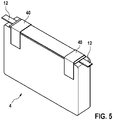
- Figure 5 shows a perspective view of an electrode assembly 4 according to another embodiment of the invention.
- the isolating member 28 is provided in form of two isolation tapes 40 applied on top of the electrode assembly.
- the isolation tapes 40 cover the areas where the electrode tabs 12 have been folded onto each other, e.g. the protruding portions 20.
Landscapes
- Chemical & Material Sciences (AREA)
- Chemical Kinetics & Catalysis (AREA)
- Electrochemistry (AREA)
- General Chemical & Material Sciences (AREA)
- Engineering & Computer Science (AREA)
- Materials Engineering (AREA)
- Manufacturing & Machinery (AREA)
- Connection Of Batteries Or Terminals (AREA)
- Secondary Cells (AREA)
Claims (7)
- Batteriezelle (2), insbesondere eine prismatische Lithiumionenzelle, wobei die Batteriezelle (2) eine Elektrodenanordnung (4), ein Batteriegehäuse (6) zur Unterbringung der Elektrodenanordnung (4) und eine Kappenanordnung (8) zum Verschließen des Batteriegehäuses (6) umfasst, wobei die Kappenanordnung (8) einen Satz von darauf angeordneten Klemmen (10) umfasst,wobei die Elektrodenanordnung (4) einen ersten und einen zweiten Stapel (24, 26) von ersten Elektrodenplatten (14), Separatorplatten und zweiten Elektrodenplatten (16) umfasst, die aufeinander gestapelt sind,
wobei die erste und die zweite Platte (14, 16) mit Elektrodenfahnen (12) zur externen elektrischen Verbindung der Elektrodenanordnung (4) mit den Klemmen (10) ausgestattet sind, wobei die Elektrodenfahnen (12) der zweiten Platten (16) gegenüber von den jeweiligen Elektrodenfahnen (12) der ersten Elektrodenplatten (14) angeordnet sind, undjede Elektrodenfahne (12) einen Sockelabschnitt (22), der sich von der Elektrodenplatte (14, 16) erstreckt, einen vorspringenden Abschnitt (20), einen Biegeabschnitt (18) und einen Verbindungsabschnitt (30) an der Spitze des Biegeabschnitts (18) umfasst, wobei der vorspringende Abschnitt (20) den Zwischenabschnitt zwischen dem Sockelabschnitt (22) und dem Biegeabschnitt (18) definiert, und der Verbindungsabschnitt (30) sich an der Spitze des Biegeabschnitts (18) befindet, wobei die vorspringenden Abschnitte (20) der Elektrodenfahnen (12) des ersten und des zweiten Stapels (24, 26) einwärts zueinander in Richtung des zweiten und des dritten Stapels (26, 24) gebogen sind, so dass die vorspringenden Abschnitte (20), die Biegeabschnitte (18) und die Verbindungsabschnitte (30) des ersten Stapels (24) mit jenen des zweiten Stapels (26) überlappen, so dass die Ebenen des überlappenden vorspringenden Abschnitts (20) parallel zu der Oberseite der Elektrodenanordnung (4) sind, und die überlappenden Biegeabschnitte (18) der Elektrodenfahnen (12) mindestens einmal um eine Achse aufwärts gebogen sind, die senkrecht zu der Ebene der ersten und der zweiten Elektrodenplatte (14, 16) ist, so dass die überlappenden Verbindungsabschnitte (30) sich parallel zu der Oberseite der Elektrodenanordnung (4) erstrecken, wobei die überlappenden Verbindungsabschnitte (30) elektrisch mit den Klemmen (10) verbunden sind. - Batteriezelle (2) nach Anspruch 1, des Weiteren umfassend mindestens ein Isolierglied (28), das auf dem überlappenden vorspringenden Abschnitt (20) der Elektrodenfahnen (12) angeordnet ist.
- Batteriezelle (2) nach einem der vorhergehenden Ansprüche, wobei die Elektrodenfahnen (12) an der Ecke der Elektrodenanordnung (4) bereitgestellt werden.
- Verfahren zur Fertigung einer Batteriezelle (2), insbesondere einer prismatischen Lithiumionenzelle, wobei das Verfahren umfasst:einen Schritt des Bereitstellens einer Elektrodenanordnung (4), wobei die Elektrodenanordnung (4) einen ersten und einen zweiten Stapel (24, 26) aus ersten Elektrodenplatten (14), Separatorplatten und zweiten Elektrodenplatten (16) umfasst, die übereinander gestapelt sind, wobei die erste und die zweite Elektrodenplatte (14, 16) mit Elektrodenfahnen (12) zur externen elektrischen Verbindung der Elektrodenanordnung (4) ausgestattet sind, wobei die Elektrodenfahne (12) einen Sockelabschnitt (22), der sich von der Elektrodenplatte (14, 16) erstreckt, einen vorspringenden Abschnitt (20), einen Biegeabschnitt (18) und einen Verbindungsabschnitt (30) an der Spitze des Biegeabschnitts (18) umfasst, wobei der vorspringende Abschnitt (20) den Zwischenabschnitt zwischen dem Sockelabschnitt (22) und dem Biegeabschnitt (18) definiert, und der Verbindungsabschnitt (30) an der Spitze des Biegeabschnitts (18) angeordnet ist, wobei der Biegeabschnitt (18) und der Verbindungsabschnitt (30) sich in einem rechten Winkel zu dem Sockelabschnitt (22) auf derselben Ebene befinden,einen Schritt des Faltens der Elektrodenfahnen (12) des ersten und des zweiten Stapels (24, 26) einwärts zueinander in Richtung zu dem zweiten und dem ersten Stapel (26, 24), so dass der vorspringende Abschnitt (20), der Biegeabschnitt (18) und der Verbindungsabschnitt (30) des ersten Stapels (24) mit jenen des zweiten Stapels (26) überlappen, so dass die Ebenen des überlappenden vorspringenden Abschnitts (20) parallel zu der Oberseite der Elektrodenanordnung (4) sind, wobei dem Schritt der Schritt des Biegens des überlappenden Biegeabschnitts (18) der Elektrodenfahnen (12) aufwärts mindestens einmal um eine Achse folgt, die senkrecht zu der Ebene der ersten und zweiten Elektrodenplatte (14, 16) ist,einen Schritt des Bereitstellens einer Kappenanordnung (8) zum Verschließen des Batteriegehäuses (6), wobei die Kappenanordnung (8) einen Satz darauf angeordneter Klemmen (10) umfasst,einen Schritt des elektrischen Verbindens der Elektrodenfahnen (12) mit den Klemmen (10),einen Schritt des Bereitstellens eines Batteriegehäuses (6) zum Unterbringen der Elektrodenanordnung (4),einen Schritt des Unterbringens der Elektrodenanordnung (4) in dem Batteriegehäuse (6), undeinen Schritt des Verschließens des Batteriegehäuses (6) mit der Kappenanordnung (8).
- Verfahren nach Anspruch 4, wobei die Elektrodenfahnen (12) sich vor dem Schritt des Faltens der Elektrodenfahnen (12) der ersten und zweiten Elektrodenplatten (14, 16) über die Ränder der Elektrodenanordnung (4) hinaus erstrecken.
- Verfahren nach Anspruch 4, wobei die Elektrodenfahnen (12) sich vor dem Schritt des Faltens der Elektrodenfahnen (12) der ersten und zweiten Elektrodenplatten (14, 16) zur Mitte der Elektrodenanordnung (4) hin erstrecken.
- Verfahren nach einem der Ansprüche 4 bis 6, wobei der Schritt des elektrischen Verbindens der Elektrodenfahnen (12) mit den Klemmen (10) Laserschweißen, Ultraschallschweißen oder Clinch-Technologie umfasst.
Priority Applications (6)
| Application Number | Priority Date | Filing Date | Title |
|---|---|---|---|
| EP17152144.6A EP3352249B1 (de) | 2017-01-19 | 2017-01-19 | Batterienzelle und verfahren zur herstellung einer batteriezelle |
| HUE17152144A HUE061626T2 (hu) | 2017-01-19 | 2017-01-19 | Akkumulátor cella és eljárás annak elõállítására |
| CN201880007394.XA CN110192292B (zh) | 2017-01-19 | 2018-01-15 | 电池单元和制造电池单元的方法 |
| US16/468,970 US11121399B2 (en) | 2017-01-19 | 2018-01-15 | Battery cell and method of manufacturing a battery cell |
| KR1020197016850A KR20190101372A (ko) | 2017-01-19 | 2018-01-15 | 배터리 셀 및 배터리 셀의 제조 방법 |
| PCT/EP2018/050896 WO2018134157A1 (en) | 2017-01-19 | 2018-01-15 | Battery cell and method of manufacturing a battery cell |
Applications Claiming Priority (1)
| Application Number | Priority Date | Filing Date | Title |
|---|---|---|---|
| EP17152144.6A EP3352249B1 (de) | 2017-01-19 | 2017-01-19 | Batterienzelle und verfahren zur herstellung einer batteriezelle |
Publications (2)
| Publication Number | Publication Date |
|---|---|
| EP3352249A1 EP3352249A1 (de) | 2018-07-25 |
| EP3352249B1 true EP3352249B1 (de) | 2022-12-28 |
Family
ID=57850970
Family Applications (1)
| Application Number | Title | Priority Date | Filing Date |
|---|---|---|---|
| EP17152144.6A Active EP3352249B1 (de) | 2017-01-19 | 2017-01-19 | Batterienzelle und verfahren zur herstellung einer batteriezelle |
Country Status (6)
| Country | Link |
|---|---|
| US (1) | US11121399B2 (de) |
| EP (1) | EP3352249B1 (de) |
| KR (1) | KR20190101372A (de) |
| CN (1) | CN110192292B (de) |
| HU (1) | HUE061626T2 (de) |
| WO (1) | WO2018134157A1 (de) |
Families Citing this family (4)
| Publication number | Priority date | Publication date | Assignee | Title |
|---|---|---|---|---|
| KR102951291B1 (ko) | 2020-07-22 | 2026-04-09 | 주식회사 엘지에너지솔루션 | 전극 리드와 전압 센싱부재 간의 연결을 단순화한 배터리 모듈 및 이를 포함하는 배터리 팩 |
| JP7579429B2 (ja) | 2021-09-30 | 2024-11-07 | 香港時代新能源科技有限公司 | 電池セル及びその製造方法と製造システム、電池及び電力使用装置 |
| KR20240001371A (ko) | 2022-06-27 | 2024-01-03 | 현대자동차주식회사 | 배터리 팩 조립장치 및 조립방법 |
| EP4456268A3 (de) * | 2023-04-26 | 2025-01-15 | Volkswagen Ag | Batteriezelle sowie verfahren zur fertigung einer solchen batteriezelle |
Citations (2)
| Publication number | Priority date | Publication date | Assignee | Title |
|---|---|---|---|---|
| US20060166088A1 (en) * | 2005-01-26 | 2006-07-27 | Hokanson Karl E | Electrode connector tabs |
| US20060194108A1 (en) * | 2005-02-14 | 2006-08-31 | Biotronik Crm Patent Ag | Galvanic cell |
Family Cites Families (7)
| Publication number | Priority date | Publication date | Assignee | Title |
|---|---|---|---|---|
| US20020094478A1 (en) * | 2000-12-02 | 2002-07-18 | Arthur Holland | Electrode with flag-shaped tab |
| JP4556428B2 (ja) | 2003-12-24 | 2010-10-06 | 株式会社Gsユアサ | 電池 |
| JP4617672B2 (ja) * | 2003-12-26 | 2011-01-26 | トヨタ自動車株式会社 | ラミネート電池モジュールとその製造方法 |
| US7770064B2 (en) | 2007-10-05 | 2010-08-03 | International Business Machines Corporation | Recovery of application faults in a mirrored application environment |
| US20130216872A1 (en) * | 2012-02-21 | 2013-08-22 | Johnson Controls Technology Company | Prismatic electrochemical cell |
| KR102177505B1 (ko) | 2014-06-17 | 2020-11-11 | 삼성에스디아이 주식회사 | 이차 전지 |
| KR102177506B1 (ko) * | 2014-07-30 | 2020-11-11 | 삼성에스디아이 주식회사 | 이차 전지 및 그 제조 방법 |
-
2017
- 2017-01-19 HU HUE17152144A patent/HUE061626T2/hu unknown
- 2017-01-19 EP EP17152144.6A patent/EP3352249B1/de active Active
-
2018
- 2018-01-15 KR KR1020197016850A patent/KR20190101372A/ko not_active Withdrawn
- 2018-01-15 CN CN201880007394.XA patent/CN110192292B/zh active Active
- 2018-01-15 US US16/468,970 patent/US11121399B2/en active Active
- 2018-01-15 WO PCT/EP2018/050896 patent/WO2018134157A1/en not_active Ceased
Patent Citations (2)
| Publication number | Priority date | Publication date | Assignee | Title |
|---|---|---|---|---|
| US20060166088A1 (en) * | 2005-01-26 | 2006-07-27 | Hokanson Karl E | Electrode connector tabs |
| US20060194108A1 (en) * | 2005-02-14 | 2006-08-31 | Biotronik Crm Patent Ag | Galvanic cell |
Also Published As
| Publication number | Publication date |
|---|---|
| WO2018134157A1 (en) | 2018-07-26 |
| KR20190101372A (ko) | 2019-08-30 |
| HUE061626T2 (hu) | 2023-07-28 |
| CN110192292A (zh) | 2019-08-30 |
| US20200083557A1 (en) | 2020-03-12 |
| US11121399B2 (en) | 2021-09-14 |
| CN110192292B (zh) | 2022-10-04 |
| EP3352249A1 (de) | 2018-07-25 |
Similar Documents
| Publication | Publication Date | Title |
|---|---|---|
| KR101395016B1 (ko) | 단차를 갖는 전극 조립체 및 이를 포함하는 전지셀, 전지팩 및 디바이스 | |
| KR100848788B1 (ko) | 결합부에서 전극 탭들의 크기가 동일한 전극조립체 및 이를포함하고 있는 전기화학 셀 | |
| EP3139435B1 (de) | Schrittweise elektrodenanordnung mit unterschiedlich geformten ecken und sekundärbatterie, batteriepackung und vorrichtung damit | |
| KR102739035B1 (ko) | 이차 전지용 전지 케이스 및 파우치 형 이차 전지 | |
| US9478773B2 (en) | Battery cell of asymmetric structure and battery pack employed with the same | |
| KR101379957B1 (ko) | 단차를 갖는 전극 조립체 및 이를 포함하는 전지셀, 전지팩 및 디바이스 | |
| EP2958177B1 (de) | Elektrodenanordnung mit abgerundeten ecken | |
| US8673476B2 (en) | Electrode assembly having stable lead-tap joint and electrochemical cell containing them | |
| EP3255705B1 (de) | Elektrodenanordnung mit elektrodenplatten mit elektrodenplattenerweiterungen | |
| US11121399B2 (en) | Battery cell and method of manufacturing a battery cell | |
| US20090181298A1 (en) | Integral electrochemical device | |
| KR20210124944A (ko) | 전극조립체 | |
| KR101482385B1 (ko) | 단면 음극을 포함하는 단차를 갖는 전극 조립체 | |
| KR100277638B1 (ko) | 전극 조립체 제조방법과 전극 조립체 및 이 전극 조립체를 이용한 전지 | |
| US20250087802A1 (en) | Stack-type electrode assembly with improved cell capacity | |
| KR101876614B1 (ko) | 복합 구조로 형성된 전극조립체 |
Legal Events
| Date | Code | Title | Description |
|---|---|---|---|
| PUAI | Public reference made under article 153(3) epc to a published international application that has entered the european phase |
Free format text: ORIGINAL CODE: 0009012 |
|
| STAA | Information on the status of an ep patent application or granted ep patent |
Free format text: STATUS: THE APPLICATION HAS BEEN PUBLISHED |
|
| AK | Designated contracting states |
Kind code of ref document: A1 Designated state(s): AL AT BE BG CH CY CZ DE DK EE ES FI FR GB GR HR HU IE IS IT LI LT LU LV MC MK MT NL NO PL PT RO RS SE SI SK SM TR |
|
| AX | Request for extension of the european patent |
Extension state: BA ME |
|
| STAA | Information on the status of an ep patent application or granted ep patent |
Free format text: STATUS: REQUEST FOR EXAMINATION WAS MADE |
|
| 17P | Request for examination filed |
Effective date: 20190124 |
|
| RBV | Designated contracting states (corrected) |
Designated state(s): AL AT BE BG CH CY CZ DE DK EE ES FI FR GB GR HR HU IE IS IT LI LT LU LV MC MK MT NL NO PL PT RO RS SE SI SK SM TR |
|
| RAP1 | Party data changed (applicant data changed or rights of an application transferred) |
Owner name: ROBERT BOSCH GMBH Owner name: GS YUASA INTERNATIONAL LTD. |
|
| STAA | Information on the status of an ep patent application or granted ep patent |
Free format text: STATUS: EXAMINATION IS IN PROGRESS |
|
| 17Q | First examination report despatched |
Effective date: 20200305 |
|
| RAP1 | Party data changed (applicant data changed or rights of an application transferred) |
Owner name: ROBERT BOSCH GMBH Owner name: GS YUASA INTERNATIONAL LTD. |
|
| REG | Reference to a national code |
Ref country code: DE Ref legal event code: R079 Ref document number: 602017064959 Country of ref document: DE Free format text: PREVIOUS MAIN CLASS: H01M0002200000 Ipc: H01M0050540000 |
|
| GRAP | Despatch of communication of intention to grant a patent |
Free format text: ORIGINAL CODE: EPIDOSNIGR1 |
|
| STAA | Information on the status of an ep patent application or granted ep patent |
Free format text: STATUS: GRANT OF PATENT IS INTENDED |
|
| RIC1 | Information provided on ipc code assigned before grant |
Ipc: H01M 10/0525 20100101ALN20220622BHEP Ipc: H01M 50/103 20210101ALN20220622BHEP Ipc: H01M 50/54 20210101AFI20220622BHEP |
|
| RIC1 | Information provided on ipc code assigned before grant |
Ipc: H01M 10/0525 20100101ALN20220629BHEP Ipc: H01M 50/103 20210101ALN20220629BHEP Ipc: H01M 50/54 20210101AFI20220629BHEP |
|
| INTG | Intention to grant announced |
Effective date: 20220719 |
|
| GRAS | Grant fee paid |
Free format text: ORIGINAL CODE: EPIDOSNIGR3 |
|
| GRAA | (expected) grant |
Free format text: ORIGINAL CODE: 0009210 |
|
| STAA | Information on the status of an ep patent application or granted ep patent |
Free format text: STATUS: THE PATENT HAS BEEN GRANTED |
|
| AK | Designated contracting states |
Kind code of ref document: B1 Designated state(s): AL AT BE BG CH CY CZ DE DK EE ES FI FR GB GR HR HU IE IS IT LI LT LU LV MC MK MT NL NO PL PT RO RS SE SI SK SM TR |
|
| REG | Reference to a national code |
Ref country code: GB Ref legal event code: FG4D |
|
| REG | Reference to a national code |
Ref country code: CH Ref legal event code: EP |
|
| REG | Reference to a national code |
Ref country code: DE Ref legal event code: R096 Ref document number: 602017064959 Country of ref document: DE |
|
| REG | Reference to a national code |
Ref country code: AT Ref legal event code: REF Ref document number: 1541047 Country of ref document: AT Kind code of ref document: T Effective date: 20230115 |
|
| REG | Reference to a national code |
Ref country code: IE Ref legal event code: FG4D |
|
| REG | Reference to a national code |
Ref country code: LT Ref legal event code: MG9D |
|
| PG25 | Lapsed in a contracting state [announced via postgrant information from national office to epo] |
Ref country code: SE Free format text: LAPSE BECAUSE OF FAILURE TO SUBMIT A TRANSLATION OF THE DESCRIPTION OR TO PAY THE FEE WITHIN THE PRESCRIBED TIME-LIMIT Effective date: 20221228 Ref country code: NO Free format text: LAPSE BECAUSE OF FAILURE TO SUBMIT A TRANSLATION OF THE DESCRIPTION OR TO PAY THE FEE WITHIN THE PRESCRIBED TIME-LIMIT Effective date: 20230328 Ref country code: LT Free format text: LAPSE BECAUSE OF FAILURE TO SUBMIT A TRANSLATION OF THE DESCRIPTION OR TO PAY THE FEE WITHIN THE PRESCRIBED TIME-LIMIT Effective date: 20221228 Ref country code: FI Free format text: LAPSE BECAUSE OF FAILURE TO SUBMIT A TRANSLATION OF THE DESCRIPTION OR TO PAY THE FEE WITHIN THE PRESCRIBED TIME-LIMIT Effective date: 20221228 |
|
| REG | Reference to a national code |
Ref country code: NL Ref legal event code: MP Effective date: 20221228 |
|
| REG | Reference to a national code |
Ref country code: AT Ref legal event code: MK05 Ref document number: 1541047 Country of ref document: AT Kind code of ref document: T Effective date: 20221228 |
|
| PG25 | Lapsed in a contracting state [announced via postgrant information from national office to epo] |
Ref country code: RS Free format text: LAPSE BECAUSE OF FAILURE TO SUBMIT A TRANSLATION OF THE DESCRIPTION OR TO PAY THE FEE WITHIN THE PRESCRIBED TIME-LIMIT Effective date: 20221228 Ref country code: LV Free format text: LAPSE BECAUSE OF FAILURE TO SUBMIT A TRANSLATION OF THE DESCRIPTION OR TO PAY THE FEE WITHIN THE PRESCRIBED TIME-LIMIT Effective date: 20221228 Ref country code: HR Free format text: LAPSE BECAUSE OF FAILURE TO SUBMIT A TRANSLATION OF THE DESCRIPTION OR TO PAY THE FEE WITHIN THE PRESCRIBED TIME-LIMIT Effective date: 20221228 Ref country code: GR Free format text: LAPSE BECAUSE OF FAILURE TO SUBMIT A TRANSLATION OF THE DESCRIPTION OR TO PAY THE FEE WITHIN THE PRESCRIBED TIME-LIMIT Effective date: 20230329 |
|
| PG25 | Lapsed in a contracting state [announced via postgrant information from national office to epo] |
Ref country code: NL Free format text: LAPSE BECAUSE OF FAILURE TO SUBMIT A TRANSLATION OF THE DESCRIPTION OR TO PAY THE FEE WITHIN THE PRESCRIBED TIME-LIMIT Effective date: 20221228 |
|
| REG | Reference to a national code |
Ref country code: HU Ref legal event code: AG4A Ref document number: E061626 Country of ref document: HU |
|
| PG25 | Lapsed in a contracting state [announced via postgrant information from national office to epo] |
Ref country code: SM Free format text: LAPSE BECAUSE OF FAILURE TO SUBMIT A TRANSLATION OF THE DESCRIPTION OR TO PAY THE FEE WITHIN THE PRESCRIBED TIME-LIMIT Effective date: 20221228 Ref country code: RO Free format text: LAPSE BECAUSE OF FAILURE TO SUBMIT A TRANSLATION OF THE DESCRIPTION OR TO PAY THE FEE WITHIN THE PRESCRIBED TIME-LIMIT Effective date: 20221228 Ref country code: PT Free format text: LAPSE BECAUSE OF FAILURE TO SUBMIT A TRANSLATION OF THE DESCRIPTION OR TO PAY THE FEE WITHIN THE PRESCRIBED TIME-LIMIT Effective date: 20230428 Ref country code: ES Free format text: LAPSE BECAUSE OF FAILURE TO SUBMIT A TRANSLATION OF THE DESCRIPTION OR TO PAY THE FEE WITHIN THE PRESCRIBED TIME-LIMIT Effective date: 20221228 Ref country code: EE Free format text: LAPSE BECAUSE OF FAILURE TO SUBMIT A TRANSLATION OF THE DESCRIPTION OR TO PAY THE FEE WITHIN THE PRESCRIBED TIME-LIMIT Effective date: 20221228 Ref country code: CZ Free format text: LAPSE BECAUSE OF FAILURE TO SUBMIT A TRANSLATION OF THE DESCRIPTION OR TO PAY THE FEE WITHIN THE PRESCRIBED TIME-LIMIT Effective date: 20221228 Ref country code: AT Free format text: LAPSE BECAUSE OF FAILURE TO SUBMIT A TRANSLATION OF THE DESCRIPTION OR TO PAY THE FEE WITHIN THE PRESCRIBED TIME-LIMIT Effective date: 20221228 |
|
| PG25 | Lapsed in a contracting state [announced via postgrant information from national office to epo] |
Ref country code: SK Free format text: LAPSE BECAUSE OF FAILURE TO SUBMIT A TRANSLATION OF THE DESCRIPTION OR TO PAY THE FEE WITHIN THE PRESCRIBED TIME-LIMIT Effective date: 20221228 Ref country code: PL Free format text: LAPSE BECAUSE OF FAILURE TO SUBMIT A TRANSLATION OF THE DESCRIPTION OR TO PAY THE FEE WITHIN THE PRESCRIBED TIME-LIMIT Effective date: 20221228 Ref country code: IS Free format text: LAPSE BECAUSE OF FAILURE TO SUBMIT A TRANSLATION OF THE DESCRIPTION OR TO PAY THE FEE WITHIN THE PRESCRIBED TIME-LIMIT Effective date: 20230428 Ref country code: AL Free format text: LAPSE BECAUSE OF FAILURE TO SUBMIT A TRANSLATION OF THE DESCRIPTION OR TO PAY THE FEE WITHIN THE PRESCRIBED TIME-LIMIT Effective date: 20221228 |
|
| REG | Reference to a national code |
Ref country code: CH Ref legal event code: PL |
|
| PG25 | Lapsed in a contracting state [announced via postgrant information from national office to epo] |
Ref country code: MC Free format text: LAPSE BECAUSE OF FAILURE TO SUBMIT A TRANSLATION OF THE DESCRIPTION OR TO PAY THE FEE WITHIN THE PRESCRIBED TIME-LIMIT Effective date: 20221228 Ref country code: LU Free format text: LAPSE BECAUSE OF NON-PAYMENT OF DUE FEES Effective date: 20230119 |
|
| REG | Reference to a national code |
Ref country code: DE Ref legal event code: R097 Ref document number: 602017064959 Country of ref document: DE |
|
| REG | Reference to a national code |
Ref country code: BE Ref legal event code: MM Effective date: 20230131 |
|
| PG25 | Lapsed in a contracting state [announced via postgrant information from national office to epo] |
Ref country code: LI Free format text: LAPSE BECAUSE OF NON-PAYMENT OF DUE FEES Effective date: 20230131 Ref country code: DK Free format text: LAPSE BECAUSE OF FAILURE TO SUBMIT A TRANSLATION OF THE DESCRIPTION OR TO PAY THE FEE WITHIN THE PRESCRIBED TIME-LIMIT Effective date: 20221228 Ref country code: CH Free format text: LAPSE BECAUSE OF NON-PAYMENT OF DUE FEES Effective date: 20230131 |
|
| PLBE | No opposition filed within time limit |
Free format text: ORIGINAL CODE: 0009261 |
|
| STAA | Information on the status of an ep patent application or granted ep patent |
Free format text: STATUS: NO OPPOSITION FILED WITHIN TIME LIMIT |
|
| GBPC | Gb: european patent ceased through non-payment of renewal fee |
Effective date: 20230328 |
|
| PG25 | Lapsed in a contracting state [announced via postgrant information from national office to epo] |
Ref country code: BE Free format text: LAPSE BECAUSE OF NON-PAYMENT OF DUE FEES Effective date: 20230131 |
|
| 26N | No opposition filed |
Effective date: 20230929 |
|
| PG25 | Lapsed in a contracting state [announced via postgrant information from national office to epo] |
Ref country code: GB Free format text: LAPSE BECAUSE OF NON-PAYMENT OF DUE FEES Effective date: 20230328 |
|
| PG25 | Lapsed in a contracting state [announced via postgrant information from national office to epo] |
Ref country code: SI Free format text: LAPSE BECAUSE OF FAILURE TO SUBMIT A TRANSLATION OF THE DESCRIPTION OR TO PAY THE FEE WITHIN THE PRESCRIBED TIME-LIMIT Effective date: 20221228 Ref country code: IE Free format text: LAPSE BECAUSE OF NON-PAYMENT OF DUE FEES Effective date: 20230119 Ref country code: GB Free format text: LAPSE BECAUSE OF NON-PAYMENT OF DUE FEES Effective date: 20230328 Ref country code: FR Free format text: LAPSE BECAUSE OF NON-PAYMENT OF DUE FEES Effective date: 20230228 |
|
| REG | Reference to a national code |
Ref country code: DE Ref legal event code: R081 Ref document number: 602017064959 Country of ref document: DE Owner name: GS YUASA INTERNATIONAL LTD., JP Free format text: FORMER OWNERS: GS YUASA INTERNATIONAL LTD., KYOTO, JP; ROBERT BOSCH GMBH, 70469 STUTTGART, DE |
|
| REG | Reference to a national code |
Ref country code: HU Ref legal event code: GB9C Owner name: GS YUASA INTERNATIONAL LTD., JP Free format text: FORMER OWNER(S): ROBERT BOSCH GMBH, DE; GS YUASA INTERNATIONAL LTD., JP Ref country code: HU Ref legal event code: FH1C |
|
| PG25 | Lapsed in a contracting state [announced via postgrant information from national office to epo] |
Ref country code: IT Free format text: LAPSE BECAUSE OF FAILURE TO SUBMIT A TRANSLATION OF THE DESCRIPTION OR TO PAY THE FEE WITHIN THE PRESCRIBED TIME-LIMIT Effective date: 20221228 |
|
| PG25 | Lapsed in a contracting state [announced via postgrant information from national office to epo] |
Ref country code: BG Free format text: LAPSE BECAUSE OF FAILURE TO SUBMIT A TRANSLATION OF THE DESCRIPTION OR TO PAY THE FEE WITHIN THE PRESCRIBED TIME-LIMIT Effective date: 20221228 |
|
| PG25 | Lapsed in a contracting state [announced via postgrant information from national office to epo] |
Ref country code: BG Free format text: LAPSE BECAUSE OF FAILURE TO SUBMIT A TRANSLATION OF THE DESCRIPTION OR TO PAY THE FEE WITHIN THE PRESCRIBED TIME-LIMIT Effective date: 20221228 |
|
| PG25 | Lapsed in a contracting state [announced via postgrant information from national office to epo] |
Ref country code: CY Free format text: LAPSE BECAUSE OF FAILURE TO SUBMIT A TRANSLATION OF THE DESCRIPTION OR TO PAY THE FEE WITHIN THE PRESCRIBED TIME-LIMIT; INVALID AB INITIO Effective date: 20170119 |
|
| PG25 | Lapsed in a contracting state [announced via postgrant information from national office to epo] |
Ref country code: TR Free format text: LAPSE BECAUSE OF FAILURE TO SUBMIT A TRANSLATION OF THE DESCRIPTION OR TO PAY THE FEE WITHIN THE PRESCRIBED TIME-LIMIT Effective date: 20221228 |
|
| PGFP | Annual fee paid to national office [announced via postgrant information from national office to epo] |
Ref country code: HU Payment date: 20260119 Year of fee payment: 10 |
|
| PGFP | Annual fee paid to national office [announced via postgrant information from national office to epo] |
Ref country code: DE Payment date: 20251217 Year of fee payment: 10 |