EP3352355B1 - Circuit de pompe de charge, dispositif et procédé correspondants - Google Patents
Circuit de pompe de charge, dispositif et procédé correspondants Download PDFInfo
- Publication number
- EP3352355B1 EP3352355B1 EP17190831.2A EP17190831A EP3352355B1 EP 3352355 B1 EP3352355 B1 EP 3352355B1 EP 17190831 A EP17190831 A EP 17190831A EP 3352355 B1 EP3352355 B1 EP 3352355B1
- Authority
- EP
- European Patent Office
- Prior art keywords
- input
- output
- voltage
- charge pump
- circuit
- Prior art date
- Legal status (The legal status is an assumption and is not a legal conclusion. Google has not performed a legal analysis and makes no representation as to the accuracy of the status listed.)
- Active
Links
Images


Classifications
-
- H—ELECTRICITY
- H02—GENERATION; CONVERSION OR DISTRIBUTION OF ELECTRIC POWER
- H02M—APPARATUS FOR CONVERSION BETWEEN AC AND AC, BETWEEN AC AND DC, OR BETWEEN DC AND DC, AND FOR USE WITH MAINS OR SIMILAR POWER SUPPLY SYSTEMS; CONVERSION OF DC OR AC INPUT POWER INTO SURGE OUTPUT POWER; CONTROL OR REGULATION THEREOF
- H02M3/00—Conversion of DC power input into DC power output
- H02M3/02—Conversion of DC power input into DC power output without intermediate conversion into AC
- H02M3/04—Conversion of DC power input into DC power output without intermediate conversion into AC by static converters
- H02M3/06—Conversion of DC power input into DC power output without intermediate conversion into AC by static converters using resistors or capacitors, e.g. potential divider
- H02M3/07—Conversion of DC power input into DC power output without intermediate conversion into AC by static converters using resistors or capacitors, e.g. potential divider using capacitors charged and discharged alternately by semiconductor devices with control electrode, e.g. charge pumps
-
- H—ELECTRICITY
- H02—GENERATION; CONVERSION OR DISTRIBUTION OF ELECTRIC POWER
- H02M—APPARATUS FOR CONVERSION BETWEEN AC AND AC, BETWEEN AC AND DC, OR BETWEEN DC AND DC, AND FOR USE WITH MAINS OR SIMILAR POWER SUPPLY SYSTEMS; CONVERSION OF DC OR AC INPUT POWER INTO SURGE OUTPUT POWER; CONTROL OR REGULATION THEREOF
- H02M1/00—Details of apparatus for conversion
- H02M1/14—Arrangements for reducing ripples from DC input or output
- H02M1/15—Arrangements for reducing ripples from DC input or output using active elements
-
- H—ELECTRICITY
- H02—GENERATION; CONVERSION OR DISTRIBUTION OF ELECTRIC POWER
- H02M—APPARATUS FOR CONVERSION BETWEEN AC AND AC, BETWEEN AC AND DC, OR BETWEEN DC AND DC, AND FOR USE WITH MAINS OR SIMILAR POWER SUPPLY SYSTEMS; CONVERSION OF DC OR AC INPUT POWER INTO SURGE OUTPUT POWER; CONTROL OR REGULATION THEREOF
- H02M1/00—Details of apparatus for conversion
- H02M1/0003—Details of control, feedback or regulation circuits
-
- H—ELECTRICITY
- H02—GENERATION; CONVERSION OR DISTRIBUTION OF ELECTRIC POWER
- H02M—APPARATUS FOR CONVERSION BETWEEN AC AND AC, BETWEEN AC AND DC, OR BETWEEN DC AND DC, AND FOR USE WITH MAINS OR SIMILAR POWER SUPPLY SYSTEMS; CONVERSION OF DC OR AC INPUT POWER INTO SURGE OUTPUT POWER; CONTROL OR REGULATION THEREOF
- H02M1/00—Details of apparatus for conversion
- H02M1/0045—Converters combining the concepts of switch-mode regulation and linear regulation, e.g. linear pre-regulator to switching converter, linear and switching converter in parallel, same converter or same transistor operating either in linear or switching mode
Definitions
- the description relates to charge pumps.
- One or more embodiments can relate to charge pumps that can be used in a wide range of possible applications, including sensors of various kinds, for example pressure, humidity and temperature sensors.
- Charge pump circuits are components capable of performing an important role in a number of electronic devices, being able to be used to obtain, from a supply voltage, higher-value positive and negative voltages.
- MEMS devices can therefore be used (by way of example - and with the embodiments not intended to be limiting) in MEMS devices, communications interfaces (for example, the RS-232 standard), smartphones and other mobile devices, computers, regulators and voltage converters. They can be used in the driving of liquid crystals (LCDs) or LEDs, for example to generate high polarizing voltages from a lower supply voltage. Furthermore, they can be used in memories (for example, flash memories) to generate pulses for erasing data.
- LCDs liquid crystals
- LEDs for example to generate high polarizing voltages from a lower supply voltage.
- memories for example, flash memories
- charge pumps are circuits capable of generating one or more voltage levels multiplying the voltage placed at the input to the same charge pump by a determined multiple (integer). They can therefore be used (for example, in applications such as those mentioned above) to generate a voltage independent of the supply voltage and constant while the same supply voltage varies.
- the output voltage of a charge pump can be affected by a residual ripple at the clock frequency f CLK with which the same charge pump is switched.
- a charge pump used to generate the voltage to drive a switched capacitor circuit can operate with a higher clock frequency f CLK than the frequency f SC of the signals for driving the switched capacitor circuit, with noise sampled on the capacitors at the end of the sampling phase.
- the ripple on the output voltage of the charge pump can be transferred through the parasitic capacitances of the switches and be unacceptable for such applications, for example in low-noise circuit applications.
- Document US 2014/167713 A1 discloses a regulator which includes an input voltage adjusting unit configured to adjust a pumping voltage in response to a control signal varied depending on a target voltage and output the adjusted pumping voltage and a regulation unit configured to output the target voltage by regulating the adjusted pumping voltage.
- the regulator may reduce current consumption by adjusting the pumping voltage inputted according to the target voltage.
- Document US 2002/034082 A1 discloses a DC/DC converter provided with a DC power source; a reference voltage generating circuit; an amplifier which receives an electric power from the DC power source and outputs an electric power whose voltage is controlled so as to assume a target voltage value by stepping down the voltage of the electric power from the DC power source depending on a difference between the reference voltage and a detection voltage; an oscillation circuit which generates signals having a specific frequency; a voltage boosting circuit which receives the output of the amplifier and the output of the oscillation circuit, causes switching of the output of the amplifier at the specific frequency to charge a first capacitor, and performs voltage boosting by transferring the electric charges charged in the first capacitor through complementary ON/OFF switching with respect to the former switching into a second capacitor after raising substantially up to n/m time voltage (wherein n>m and n and m are integers equal to or more than 2) and charging the same therewith; and an output voltage detection circuit which generates the detection voltage depending on the output voltage of the boosting circuit, whereby a voltage
- Document WO 2008/016571 A1 discloses a voltage generation circuit generating an output voltage and including regulation circuitry that controls regulation of the output voltage to maintain the output voltage at a substantially constant level. Regulation is provided through use of different feedback circuits. By selectively disabling one of the feedback circuits, power consumption can be reduced and the other of the feedback circuits can support the continued regulation of the output voltage.
- An aim of one or more embodiments is to contribute towards meeting this demand.
- this aim can be achieved by virtue of a circuit having the characteristics referred to in claim 1 that follows.
- One or more embodiments can relate to a corresponding device (for example, among those mentioned above) as well as a corresponding method.
- One or more embodiments can provide the advantage of having a residual ripple which is not attenuated solely by the effect of the output capacitance.
- One or more embodiments can provide for placing a charge pump inside a feedback system, i.e. f the closed-loop type, with the feedback system capable of comprising two control loops.
- One or more embodiments can provide for strongly attenuating the residual ripple on the output voltage of a charge pump (for example, at the switching frequency) using values for the output capacitance that are small and therefore which can be implemented without too much difficulty.
- one or more embodiments can dynamically detect the output voltage and perform a feedback providing a correct current gain from the charge pump.
- One or more embodiments can notably reduce the ripple at the clock frequency caused by the switching of the pump switches without having to increase the output capacitance.
- One or more embodiments can be generalized to the case of any gain N with respect to the reference voltage at the input.
- One or more embodiments can provide for producing a first feedback of the output of the charge pump in conjunction with a second feedback aiming at maintaining (for example, by means of a transistor such as a MOSFET) a fixed difference between the output voltage of the charge pump and the overall output voltage of the circuit.
- One more embodiments can comprise an LDO (Low Dropout) type output configuration.
- charge pumps have formed the subject of widespread activities of study and innovation, from elementary solutions such as the one known in the literature as a "Two-Phase Voltage Doubler", or TPVD (with the charge accumulated in successive phases on a first and a second capacitor used to "pump” the charge onto an output capacitor), to more sophisticated solutions such as, for example, the one described in US 5 874 850 A .
- TPVD Phase Voltage Doubler
- the output voltage is double the input voltage. If instead the circuit driven by the charge pump absorbs a current level different from zero and increasing, then the output voltage of the charge pump tends to reduce with a ripple due to the switching of the two operating phases superimposed on the output voltage.
- the ripple caused by the switching (at the frequency f CLK ) can be reduced (only) by increasing the output capacitance.
- consideration could be given to reducing the ripple to the desired level by suitably increasing the value of the output capacitance.
- This value can however not be realizable or require the occupation of an area (and therefore a cost) that is incompatible with the application demands or usage demands.
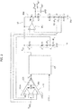
- this can be, in one or more embodiments as exemplified in Figure 1 , a charge pump with multiplication by 2.
- a charge pump circuit can be considered, as exemplified in Figure 1 , in which two first capacitors C1 are charged from a voltage V R (capable of being obtained for example from a reference voltage V REF by means of a differential input stage 10) through respective inverter stages 11 clocked by a clock signal CLK and with a second inverter stage 12 which "pumps" the charge on the capacitors C1 onto a second capacitor C2, across which there is a voltage V CP multiplied by 2 with respect to the input V R .
- One or more embodiments can in fact use charge pump circuits of different types, this being applicable also to the charge pumps CP exemplified in Figures 2 and 3 (which will be returned to later), which, instead of being charge pumps with multiplication by 2, can be charge pumps - of a type that are known per se - with multiplication by N, comprising, for example, a cascade of N-1 stages of the type described above by way of summary.
- the overall output of the circuit at the voltage V OUT (which it is desired to be equal, for example, to 2 times V REF - Figure 1 - or to N times V REF - Figures 2 and 3 ) can be provided on an output capacitor C OUT with the provision - between the output of the charge pump CP at the voltage V CP and the overall output of the circuit at the voltage V OUT - of a circuit configuration capable of realizing two feedback control loops and substantially comparable to a low dropout (LDO) configuration.
- LDO low dropout
- the first feedback loop can comprise a (first) resistive voltage divider 14 comprising a plurality of resistors connected in series between the output of the charge pump CP on which the voltage V CP is present and ground GND, with an overall value of resistance equal to N times R 1 , where N represents the multiplication value of the charge pump CP (equal to 2 in the case of Figure 1 , and N in the case of Figures 2 and 3 ).
- the divider 14 can ideally be seen as comprising N resistors with resistance value R 1 , one of which (for example the one connected to ground) is divided into two portions with resistance values equal to R 1 - ⁇ R 1 and ⁇ R 1 respectively.
- a voltage approximately equal to a submultiple N of V CP (i.e. equal to 1/N times V CP ) can be detected across the resistance R 1 - ⁇ R 1 and brought back as input - according to methods discussed hereinafter - to the differential stage 10 which generates V R from V REF .
- Referring to a voltage as "approximately" equal to a submultiple N of V CP takes into account the effect of the deviation with respect to R 1 given by ⁇ R 1 .
- the second feedback control loop can act so as to maintain the voltage V CP at a higher value, for example by an amount ⁇ V with respect to the voltage V OUT , so as to facilitate the correct operation of an output transistor (for example, MOS) 16a.
- the transistor 16a can be positioned:
- the abovesaid voltage equal to 1/N times V OUT can be obtained by means of a resistive divider 16c similar overall to the divider 14 already described previously.
- the divider 16c can ideally be seen as comprising N resistors with resistance value R 2 , one of which (for example the second from the one connected to ground) is divided into two portions with resistance values equal to R 2 - ⁇ R 2 and ⁇ R 2 respectively.
- a voltage equal to a submultiple N of V OUT (i.e. equal to 1/N times V OUT ) can be detected across the resistor of value R 2 connected to ground GND and brought to the input (for example, non-inverting) of the differential stage 16b.
- a voltage approximately equal to a submultiple N of V OUT (i.e. equal to 1/N times V OUT ) can be detected on the resistance R 2 + ⁇ R 2 and brought back as input - also here according to methods discussed later - to the differential stage 10 which generates V R from V REF .
- a voltage as "approximately" equal to a submultiple N of V CP takes into account the effect of the deviation with respect to R 2 given by ⁇ R 2 .
- the attenuation of the ripple of the closed-loop charge pump configuration can be facilitated not only by virtue of the filtering effect of the output capacitance C OUT , but also by virtue of the attenuating effect of the "Power Supply Rejection Ratio" (PSRR) of the LDO type circuit configuration described previously.
- PSRR Power Supply Rejection Ratio
- the additional attenuation being derived from the PSRR contribution can be added to the filtering effect of the capacitance C OUT , with the advantage of being able to strongly attenuate the ripple signal even by using reduced values of the output capacitance C OUT .
- a high value can be chosen for the resistances R 1 and R 2 , so as to reduce the current consumption of the resistive dividers 14 and 16c produced using these resistances.
- the outputs of the two differential circuits 101a, 101b can be summed in a summing node 102 (for example, with current mirror) to generate the voltage V R across a unity-gain stage 103.
- ⁇ R 1 and ⁇ R 2 i.e. of the two "deviations" of the resistive values with respect to the values R 1 and R 2 linked to the multiplication factor of the charge pump CP
- ⁇ V indicates the difference between V CP and V OUT , i.e., for example, the amount by which V CP can be maintained higher than the voltage V OUT .
- Figure 3 exemplifies (with reference to the diagram of Figure 2 , but this possibility applies also to the diagram of Figure 1 ) the possibility, in one or more embodiments, of:
- the insertion of the unit 20 enables a further reduction of the ripple superimposed on the output signal at the clock frequency f CLK .
- the value of the division factor ⁇ can be chosen (for example, as a function of the application context and usage context) to be the value (between 0 and 1) which minimizes the abovesaid ripple.
- the unit 20 can "read" the clock signal CLK of the charge pump and generate the signal which drives the switch S1 which divides the output capacitance C OUT into two.
- the unit 20 can comprise:
- the unit 20 can therefore open the switch S1 for a brief time interval at the switching edge of the clock signal CLK, thus reducing the propagation of the ripple signal at the output.
- the transient response after a current spike at the output is dictated primarily by the free-running operation of the charge pump without affecting the noise performance of the capacitors with the residual ripple at the sampling intervals duly reduced.
- said second feedback loop can comprise a transistor (for example, 16a) positioned with its current path (for example, source-drain if the transistor is a FET such as a MOSFET) between the output of the charge pump and the output capacitance.
- a transistor for example, 16a
- its current path for example, source-drain if the transistor is a FET such as a MOSFET
- said transistor can have a control terminal (for example, a gate, if the transistor is a FET such as a MOSFET) driven by a differential stage (for example, 16b) sensitive to the reference voltage on the reference terminal of the input stage and to a submultiple equal to said multiple N (i.e. V OUT /N) of the output voltage of the circuit.
- a control terminal for example, a gate, if the transistor is a FET such as a MOSFET
- a differential stage for example, 16b
- One or more embodiments can comprise a voltage divider (for example, 16c) between the output capacitance and said differential stage, said voltage divider having a division ratio (i.e. by which value the output of the divider is divided with respect to the input of the divider) equal to said multiple N.
- a voltage divider for example, 16c
- said voltage divider having a division ratio (i.e. by which value the output of the divider is divided with respect to the input of the divider) equal to said multiple N.
- the input stage can comprise:
- said first and second voltage divider can have respective division ratios (i.e. by which values the output of the divider is divided with respect to the input of the divider) with deviations of opposite sign (for example, the deviations or offsets - ⁇ R 1 , + ⁇ R 2 with respect to R 1 and R 2 ) with respect to said multiple N.
- One or more embodiments can comprise a voltage divider (for example, the divider 16c) coupled to the output capacitance and having a first tap point (for example, R 2 ) towards said differential stage (for example, 16b) and a second tap point (for example, R 2 + ⁇ R 2 ) towards the second feedback input (101b) of the input stage.
- a voltage divider for example, the divider 16c
- R 2 first tap point
- said differential stage for example, 16b
- a second tap point for example, R 2 + ⁇ R 2
- an electronic device for example, a sensor
- a charge pump circuit according to any of the preceding claims.
Landscapes
- Engineering & Computer Science (AREA)
- Power Engineering (AREA)
- Dc-Dc Converters (AREA)
- Piezo-Electric Or Mechanical Vibrators, Or Delay Or Filter Circuits (AREA)
Claims (11)
- Circuit comprenant :- une pompe de charge (CP) ayant une tension d'entrée (VR) et une tension de sortie (VCP) qui est un multiple N de la tension d'entrée (VR), la pompe de charge (CP) ayant une entrée d'horloge (CLK),- un étage d'entrée (10) avec une borne de référence destinée à recevoir une tension de référence (VREF) et une borne de sortie couplée à la pompe de charge (CP) pour appliquer la tension d'entrée (VR) à la pompe de charge (CP),- au moins une capacité de sortie (COUT) couplée (14, 16) à la pompe de charge (CP) et pouvant être chargée à une tension de sortie (VOUT) du circuit,dans lequel l'étage d'entrée (10) comprend :- une première entrée de rétroaction différentielle (101a) ayant une première borne couplée à la borne de référence, une deuxième borne couplée à la sortie (VCP) de la pompe de charge (CP) et une première borne de sortie,- une deuxième entrée de rétroaction différentielle (101b) ayant une première borne couplée à la borne de référence, une deuxième borne couplée à la capacité de sortie (COUT) et une deuxième borne de sortie, et- un nœud de sommation (102) couplé aux première et deuxième bornes de sortie desdites première (101a) et deuxième (101b) entrées de rétroaction différentielle de manière telle que la tension d'entrée (VR) appliquée par l'étage d'entrée à la pompe de charge (CP) est une fonction (103) des signaux de rétroaction présents sur lesdites première (101a) et deuxième (101b) entrées de rétroaction différentielle de l'étage d'entrée (10),le circuit comprenant :- un réseau de rétroaction (14, 16) comprenant une première boucle de rétroaction (14) pour renvoyer la tension de sortie (VCP) de la pompe de charge (CP) vers la première entrée de rétroaction différentielle (101a) de l'étage d'entrée (10) et une deuxième boucle de rétroaction (16a, 16b, 16c) configurée pour agir sur la deuxième entrée de rétroaction différentielle (101b) de l'étage d'entrée (10) pour maintenir un décalage fixe entre la tension de sortie (VCP) de la pompe de charge (CP) et la tension de sortie (VOUT) du circuit.
- Circuit selon la revendication 1, comprenant ladite capacité de sortie (COUT) divisée entre deux condensateurs de sortie (α.COUT ; (1-α).COUT), avec un interrupteur (S1) placé entre les deux condensateurs de sortie et avec une unité de pilotage (20) pour piloter l'interrupteur (S1) couplée à l'entrée d'horloge (CLK) de la pompe de charge (CP), l'interrupteur (S1) pouvant être ouvert par l'unité de pilotage (20) aux fronts de commutation du signal d'horloge (CLK) présent à l'entrée d'horloge (CLK) de la pompe de charge (CP).
- Circuit selon la revendication 1 ou 2, dans lequel ladite deuxième boucle de rétroaction (16) comprend un transistor (16a) positionné avec son chemin de courant entre la sortie de la pompe de charge (CP) et la capacité de sortie (COUT).
- Circuit selon la revendication 3, dans lequel ledit transistor (16a) a une borne de commande pilotée par un étage différentiel (16b) sensible à la tension de référence (VREF) sur la borne de référence de l'étage d'entrée (10) et à un sous-multiple égal audit multiple N de la tension de sortie (VOUT) du circuit.
- Circuit selon la revendication 4, comprenant un diviseur de tension (16c) entre la capacité de sortie (COUT) et ledit étage différentiel (16b), ledit diviseur de tension ayant un rapport de division égal audit multiple N.
- Circuit selon la revendication 1, comprenant :- un premier diviseur de tension (14) entre la sortie (VCP) de la pompe de charge (CP) et la première entrée de rétroaction différentielle (101a) de l'étage d'entrée (10), et- un deuxième diviseur de tension (16c) entre la capacité de sortie (COUT) et la deuxième entrée de rétroaction différentielle (101b) de l'étage d'entrée (10).
- Circuit selon la revendication 6, dans lequel lesdits premier (14) et deuxième (16c) diviseurs de tension ont des rapports de division respectifs avec des écarts de signe contraire (-ΔR1, +ΔR2) par rapport audit multiple N.
- Circuit selon la revendication 5 en association avec l'une quelconque des revendications 1, 6 et 7, comprenant un diviseur de tension (16c) couplé à la capacité de sortie (COUT) et ayant un premier point de prise (R2) vers ledit étage différentiel (16b) et un deuxième point de prise (R2 + ΔR2) vers la deuxième entrée de rétroaction différentielle (101b) de l'étage d'entrée (10).
- Dispositif électronique comprenant un circuit (10, CP, 14, 16) selon l'une quelconque des revendications précédentes.
- Procédé comprenant le fait de fournir un circuit comportant :- une pompe de charge (CP) ayant une tension d'entrée (VR) et une tension de sortie (VCP) qui est un multiple N de la tension d'entrée (VR), la pompe de charge (CP) ayant une entrée d'horloge (CLK),- un étage d'entrée (10) avec une borne de référence destinée à recevoir une tension de référence (VREF) et une borne de sortie couplée à la pompe de charge (CP) pour appliquer la tension d'entrée (VR) à la pompe de charge (CP),- au moins une capacité de sortie (COUT) couplée (14, 16) à la pompe de charge (CP) et pouvant être chargée à une tension de sortie (VOUT) du circuit,dans lequel l'étage d'entrée (10) comprend :- une première entrée de rétroaction différentielle (101a) ayant une première borne couplée à la borne de référence, une deuxième borne couplée à la sortie (VCP) de la pompe de charge (CP) et une première borne de sortie,- une deuxième entrée de rétroaction différentielle (101b) ayant une première borne couplée à la borne de référence, une deuxième borne couplée à la capacité de sortie (COUT) et une deuxième borne de sortie, et- un nœud de sommation (102) couplé aux première et deuxième bornes de sortie desdites première (101a) et deuxième (101b) entrées de rétroaction différentielle de manière telle que la tension d'entrée (VR) appliquée par l'étage d'entrée à la pompe de charge (CP) est une fonction (103) des signaux de rétroaction présents sur lesdites première (101a) et deuxième (101b) entrées de rétroaction différentielle de l'étage d'entrée (10),le procédé comprenant :- la fourniture d'une première rétroaction (14) de la tension de sortie (VCP) de la pompe de charge (CP) vers la première entrée de rétroaction différentielle (101a) de l'étage d'entrée (10) et une deuxième rétroaction (16a, 16b, 16c) agissant sur la deuxième entrée de rétroaction différentielle (101b) de l'étage d'entrée (10) pour maintenir un décalage fixe entre la tension de sortie (VCP) de la pompe de charge (CP) et la tension de sortie (VOUT) du circuit.
- Procédé selon la revendication 10, comprenant le fait de diviser ladite capacité de sortie (COUT) entre deux condensateurs de sortie (α.COUT ; (1-α).COUT), avec un interrupteur (S1) intercalé entre les deux condensateurs de sortie, en ouvrant l'interrupteur aux fronts de commutation du signal d'horloge (CLK) présent à l'entrée d'horloge (CLK) de la pompe de charge (CP).
Applications Claiming Priority (1)
| Application Number | Priority Date | Filing Date | Title |
|---|---|---|---|
| IT102017000007428A IT201700007428A1 (it) | 2017-01-24 | 2017-01-24 | Circuito a pompa di carica, dispositivo e procedimento corrispondenti |
Publications (2)
| Publication Number | Publication Date |
|---|---|
| EP3352355A1 EP3352355A1 (fr) | 2018-07-25 |
| EP3352355B1 true EP3352355B1 (fr) | 2020-03-11 |
Family
ID=58737777
Family Applications (1)
| Application Number | Title | Priority Date | Filing Date |
|---|---|---|---|
| EP17190831.2A Active EP3352355B1 (fr) | 2017-01-24 | 2017-09-13 | Circuit de pompe de charge, dispositif et procédé correspondants |
Country Status (4)
| Country | Link |
|---|---|
| US (1) | US10848058B2 (fr) |
| EP (1) | EP3352355B1 (fr) |
| CN (2) | CN207304376U (fr) |
| IT (1) | IT201700007428A1 (fr) |
Families Citing this family (3)
| Publication number | Priority date | Publication date | Assignee | Title |
|---|---|---|---|---|
| CN111917293B (zh) * | 2020-06-22 | 2021-06-22 | 东南大学 | 一种多电压域复合反馈模式的开关电容dc-dc转换器 |
| US11646658B2 (en) * | 2020-11-25 | 2023-05-09 | Stmicroelectronics S.R.L. | Charge pump circuit, corresponding device and method |
| US12216485B2 (en) * | 2021-07-08 | 2025-02-04 | Novatek Microelectronics Corp. | Output circuit and related control method with pumping compensation |
Citations (3)
| Publication number | Priority date | Publication date | Assignee | Title |
|---|---|---|---|---|
| US20060181340A1 (en) * | 2005-02-17 | 2006-08-17 | Zywyn Corporation | Regulating charge pump |
| WO2008016571A1 (fr) * | 2006-07-31 | 2008-02-07 | Sandisk Corporation | Régulation de pompe de charge hybride avec circuits de rétroaction sélectionnables |
| EP2065780A1 (fr) * | 2007-11-30 | 2009-06-03 | Austriamicrosystems AG | Ensemble de pompe à charge contrôlée et procédé pour le contrôle d'une pompe à charge synchronisée |
Family Cites Families (12)
| Publication number | Priority date | Publication date | Assignee | Title |
|---|---|---|---|---|
| DE69408665T2 (de) | 1994-08-12 | 1998-10-15 | Cons Ric Microelettronica | Spannungserhöher vom Ladungspumpentype |
| EP0846996B1 (fr) * | 1996-12-05 | 2003-03-26 | STMicroelectronics S.r.l. | Circuit de commande d'un transistor de puissance pour régulation de tension |
| JP3666805B2 (ja) * | 2000-09-19 | 2005-06-29 | ローム株式会社 | Dc/dcコンバータ |
| ITMI20031924A1 (it) | 2003-10-07 | 2005-04-08 | Atmel Corp | Convertitore da digitale ad analogico ad alta precisione con consumo di energia ottimizzato. |
| US7944277B1 (en) * | 2008-01-04 | 2011-05-17 | Marvell International Ltd. | Circuit and methods of adaptive charge-pump regulation |
| TWI357543B (en) | 2008-03-24 | 2012-02-01 | Novatek Microelectronics Corp | Apparatus of dynamic feed-back control charge pump |
| CN102005917B (zh) * | 2010-12-15 | 2012-11-14 | 电子科技大学 | 一种恒压输出电荷泵电路 |
| KR102021415B1 (ko) * | 2012-12-14 | 2019-09-16 | 에스케이하이닉스 주식회사 | 전압 생성 회로 |
| KR20140078986A (ko) * | 2012-12-18 | 2014-06-26 | 에스케이하이닉스 주식회사 | 레귤레이터, 전압 발생기, 반도체 메모리 장치 및 전압 발생 방법 |
| US9645591B2 (en) * | 2014-01-09 | 2017-05-09 | Qualcomm Incorporated | Charge sharing linear voltage regulator |
| CN104518663B (zh) | 2014-07-18 | 2017-03-29 | 上海华虹宏力半导体制造有限公司 | 负压电荷泵反馈电路 |
| CN105915046B (zh) * | 2016-04-27 | 2018-08-28 | 二十一世纪(北京)微电子技术有限公司 | 一种电荷泵控制电路 |
-
2017
- 2017-01-24 IT IT102017000007428A patent/IT201700007428A1/it unknown
- 2017-09-13 EP EP17190831.2A patent/EP3352355B1/fr active Active
- 2017-09-19 CN CN201721201316.2U patent/CN207304376U/zh not_active Withdrawn - After Issue
- 2017-09-19 CN CN201710847537.5A patent/CN108347162B/zh active Active
- 2017-10-30 US US15/797,643 patent/US10848058B2/en active Active
Patent Citations (3)
| Publication number | Priority date | Publication date | Assignee | Title |
|---|---|---|---|---|
| US20060181340A1 (en) * | 2005-02-17 | 2006-08-17 | Zywyn Corporation | Regulating charge pump |
| WO2008016571A1 (fr) * | 2006-07-31 | 2008-02-07 | Sandisk Corporation | Régulation de pompe de charge hybride avec circuits de rétroaction sélectionnables |
| EP2065780A1 (fr) * | 2007-11-30 | 2009-06-03 | Austriamicrosystems AG | Ensemble de pompe à charge contrôlée et procédé pour le contrôle d'une pompe à charge synchronisée |
Also Published As
| Publication number | Publication date |
|---|---|
| CN207304376U (zh) | 2018-05-01 |
| US20180212514A1 (en) | 2018-07-26 |
| CN108347162A (zh) | 2018-07-31 |
| EP3352355A1 (fr) | 2018-07-25 |
| CN108347162B (zh) | 2020-09-15 |
| IT201700007428A1 (it) | 2018-07-24 |
| US10848058B2 (en) | 2020-11-24 |
Similar Documents
| Publication | Publication Date | Title |
|---|---|---|
| US11444537B2 (en) | Power converters and compensation circuits thereof | |
| US9264053B2 (en) | Variable frequency charge pump | |
| US8283907B1 (en) | Boost regulator with pulse frequency mode of operation having substantially constant percentage output ripple and frequency | |
| US9811101B2 (en) | Power converter and method for regulating line transient response of the power converter | |
| JP6118809B2 (ja) | マスタースレーブ低ノイズチャージポンプ回路及び方法 | |
| EP3516474B1 (fr) | Dispositif et procédé permettant de stabiliser une tension d'alimentation | |
| US8289009B1 (en) | Low dropout (LDO) regulator with ultra-low quiescent current | |
| EP3352355B1 (fr) | Circuit de pompe de charge, dispositif et procédé correspondants | |
| US8749301B2 (en) | Power management device and power management method of touchable control system | |
| US20250293604A1 (en) | Multi-phase voltage regulator system | |
| US10320296B2 (en) | Multi-phase voltage regulator system | |
| JP2007089242A (ja) | チャージポンプ式昇圧回路を有する半導体装置 | |
| US11916486B2 (en) | Type-2 compensation with reduced quiescent current | |
| US9866111B1 (en) | Regulated charge pump circuit | |
| EP3832431B1 (fr) | Circuit de génération d'amplification, circuit et puce associés, et dispositif portable | |
| US10715121B2 (en) | Parameter-independent ramp signal generation | |
| Subasinghage et al. | Pole-zero analysis of supercapacitor-assisted low-dropout (SCALDO) regulator | |
| US20160301301A1 (en) | Voltage supply circuits and controlling methods therefor | |
| Sh | Power Supply Ratio Improvement Using Self-Calibration in Voltage Regulators |
Legal Events
| Date | Code | Title | Description |
|---|---|---|---|
| PUAI | Public reference made under article 153(3) epc to a published international application that has entered the european phase |
Free format text: ORIGINAL CODE: 0009012 |
|
| STAA | Information on the status of an ep patent application or granted ep patent |
Free format text: STATUS: THE APPLICATION HAS BEEN PUBLISHED |
|
| AK | Designated contracting states |
Kind code of ref document: A1 Designated state(s): AL AT BE BG CH CY CZ DE DK EE ES FI FR GB GR HR HU IE IS IT LI LT LU LV MC MK MT NL NO PL PT RO RS SE SI SK SM TR |
|
| AX | Request for extension of the european patent |
Extension state: BA ME |
|
| STAA | Information on the status of an ep patent application or granted ep patent |
Free format text: STATUS: REQUEST FOR EXAMINATION WAS MADE |
|
| 17P | Request for examination filed |
Effective date: 20190122 |
|
| RBV | Designated contracting states (corrected) |
Designated state(s): AL AT BE BG CH CY CZ DE DK EE ES FI FR GB GR HR HU IE IS IT LI LT LU LV MC MK MT NL NO PL PT RO RS SE SI SK SM TR |
|
| STAA | Information on the status of an ep patent application or granted ep patent |
Free format text: STATUS: EXAMINATION IS IN PROGRESS |
|
| 17Q | First examination report despatched |
Effective date: 20190625 |
|
| GRAP | Despatch of communication of intention to grant a patent |
Free format text: ORIGINAL CODE: EPIDOSNIGR1 |
|
| STAA | Information on the status of an ep patent application or granted ep patent |
Free format text: STATUS: GRANT OF PATENT IS INTENDED |
|
| INTG | Intention to grant announced |
Effective date: 20191016 |
|
| GRAS | Grant fee paid |
Free format text: ORIGINAL CODE: EPIDOSNIGR3 |
|
| GRAA | (expected) grant |
Free format text: ORIGINAL CODE: 0009210 |
|
| STAA | Information on the status of an ep patent application or granted ep patent |
Free format text: STATUS: THE PATENT HAS BEEN GRANTED |
|
| AK | Designated contracting states |
Kind code of ref document: B1 Designated state(s): AL AT BE BG CH CY CZ DE DK EE ES FI FR GB GR HR HU IE IS IT LI LT LU LV MC MK MT NL NO PL PT RO RS SE SI SK SM TR |
|
| REG | Reference to a national code |
Ref country code: GB Ref legal event code: FG4D |
|
| REG | Reference to a national code |
Ref country code: CH Ref legal event code: EP |
|
| REG | Reference to a national code |
Ref country code: AT Ref legal event code: REF Ref document number: 1244399 Country of ref document: AT Kind code of ref document: T Effective date: 20200315 |
|
| REG | Reference to a national code |
Ref country code: DE Ref legal event code: R096 Ref document number: 602017012841 Country of ref document: DE |
|
| REG | Reference to a national code |
Ref country code: IE Ref legal event code: FG4D |
|
| PG25 | Lapsed in a contracting state [announced via postgrant information from national office to epo] |
Ref country code: FI Free format text: LAPSE BECAUSE OF FAILURE TO SUBMIT A TRANSLATION OF THE DESCRIPTION OR TO PAY THE FEE WITHIN THE PRESCRIBED TIME-LIMIT Effective date: 20200311 Ref country code: NO Free format text: LAPSE BECAUSE OF FAILURE TO SUBMIT A TRANSLATION OF THE DESCRIPTION OR TO PAY THE FEE WITHIN THE PRESCRIBED TIME-LIMIT Effective date: 20200611 Ref country code: RS Free format text: LAPSE BECAUSE OF FAILURE TO SUBMIT A TRANSLATION OF THE DESCRIPTION OR TO PAY THE FEE WITHIN THE PRESCRIBED TIME-LIMIT Effective date: 20200311 |
|
| REG | Reference to a national code |
Ref country code: NL Ref legal event code: MP Effective date: 20200311 |
|
| PG25 | Lapsed in a contracting state [announced via postgrant information from national office to epo] |
Ref country code: LV Free format text: LAPSE BECAUSE OF FAILURE TO SUBMIT A TRANSLATION OF THE DESCRIPTION OR TO PAY THE FEE WITHIN THE PRESCRIBED TIME-LIMIT Effective date: 20200311 Ref country code: SE Free format text: LAPSE BECAUSE OF FAILURE TO SUBMIT A TRANSLATION OF THE DESCRIPTION OR TO PAY THE FEE WITHIN THE PRESCRIBED TIME-LIMIT Effective date: 20200311 Ref country code: HR Free format text: LAPSE BECAUSE OF FAILURE TO SUBMIT A TRANSLATION OF THE DESCRIPTION OR TO PAY THE FEE WITHIN THE PRESCRIBED TIME-LIMIT Effective date: 20200311 Ref country code: GR Free format text: LAPSE BECAUSE OF FAILURE TO SUBMIT A TRANSLATION OF THE DESCRIPTION OR TO PAY THE FEE WITHIN THE PRESCRIBED TIME-LIMIT Effective date: 20200612 Ref country code: BG Free format text: LAPSE BECAUSE OF FAILURE TO SUBMIT A TRANSLATION OF THE DESCRIPTION OR TO PAY THE FEE WITHIN THE PRESCRIBED TIME-LIMIT Effective date: 20200611 |
|
| REG | Reference to a national code |
Ref country code: LT Ref legal event code: MG4D |
|
| PG25 | Lapsed in a contracting state [announced via postgrant information from national office to epo] |
Ref country code: NL Free format text: LAPSE BECAUSE OF FAILURE TO SUBMIT A TRANSLATION OF THE DESCRIPTION OR TO PAY THE FEE WITHIN THE PRESCRIBED TIME-LIMIT Effective date: 20200311 |
|
| PG25 | Lapsed in a contracting state [announced via postgrant information from national office to epo] |
Ref country code: SM Free format text: LAPSE BECAUSE OF FAILURE TO SUBMIT A TRANSLATION OF THE DESCRIPTION OR TO PAY THE FEE WITHIN THE PRESCRIBED TIME-LIMIT Effective date: 20200311 Ref country code: EE Free format text: LAPSE BECAUSE OF FAILURE TO SUBMIT A TRANSLATION OF THE DESCRIPTION OR TO PAY THE FEE WITHIN THE PRESCRIBED TIME-LIMIT Effective date: 20200311 Ref country code: LT Free format text: LAPSE BECAUSE OF FAILURE TO SUBMIT A TRANSLATION OF THE DESCRIPTION OR TO PAY THE FEE WITHIN THE PRESCRIBED TIME-LIMIT Effective date: 20200311 Ref country code: RO Free format text: LAPSE BECAUSE OF FAILURE TO SUBMIT A TRANSLATION OF THE DESCRIPTION OR TO PAY THE FEE WITHIN THE PRESCRIBED TIME-LIMIT Effective date: 20200311 Ref country code: CZ Free format text: LAPSE BECAUSE OF FAILURE TO SUBMIT A TRANSLATION OF THE DESCRIPTION OR TO PAY THE FEE WITHIN THE PRESCRIBED TIME-LIMIT Effective date: 20200311 Ref country code: PT Free format text: LAPSE BECAUSE OF FAILURE TO SUBMIT A TRANSLATION OF THE DESCRIPTION OR TO PAY THE FEE WITHIN THE PRESCRIBED TIME-LIMIT Effective date: 20200805 Ref country code: SK Free format text: LAPSE BECAUSE OF FAILURE TO SUBMIT A TRANSLATION OF THE DESCRIPTION OR TO PAY THE FEE WITHIN THE PRESCRIBED TIME-LIMIT Effective date: 20200311 Ref country code: IS Free format text: LAPSE BECAUSE OF FAILURE TO SUBMIT A TRANSLATION OF THE DESCRIPTION OR TO PAY THE FEE WITHIN THE PRESCRIBED TIME-LIMIT Effective date: 20200711 |
|
| REG | Reference to a national code |
Ref country code: AT Ref legal event code: MK05 Ref document number: 1244399 Country of ref document: AT Kind code of ref document: T Effective date: 20200311 |
|
| REG | Reference to a national code |
Ref country code: DE Ref legal event code: R097 Ref document number: 602017012841 Country of ref document: DE |
|
| PLBE | No opposition filed within time limit |
Free format text: ORIGINAL CODE: 0009261 |
|
| STAA | Information on the status of an ep patent application or granted ep patent |
Free format text: STATUS: NO OPPOSITION FILED WITHIN TIME LIMIT |
|
| PG25 | Lapsed in a contracting state [announced via postgrant information from national office to epo] |
Ref country code: ES Free format text: LAPSE BECAUSE OF FAILURE TO SUBMIT A TRANSLATION OF THE DESCRIPTION OR TO PAY THE FEE WITHIN THE PRESCRIBED TIME-LIMIT Effective date: 20200311 Ref country code: AT Free format text: LAPSE BECAUSE OF FAILURE TO SUBMIT A TRANSLATION OF THE DESCRIPTION OR TO PAY THE FEE WITHIN THE PRESCRIBED TIME-LIMIT Effective date: 20200311 Ref country code: IT Free format text: LAPSE BECAUSE OF FAILURE TO SUBMIT A TRANSLATION OF THE DESCRIPTION OR TO PAY THE FEE WITHIN THE PRESCRIBED TIME-LIMIT Effective date: 20200311 Ref country code: DK Free format text: LAPSE BECAUSE OF FAILURE TO SUBMIT A TRANSLATION OF THE DESCRIPTION OR TO PAY THE FEE WITHIN THE PRESCRIBED TIME-LIMIT Effective date: 20200311 |
|
| 26N | No opposition filed |
Effective date: 20201214 |
|
| PG25 | Lapsed in a contracting state [announced via postgrant information from national office to epo] |
Ref country code: SI Free format text: LAPSE BECAUSE OF FAILURE TO SUBMIT A TRANSLATION OF THE DESCRIPTION OR TO PAY THE FEE WITHIN THE PRESCRIBED TIME-LIMIT Effective date: 20200311 Ref country code: PL Free format text: LAPSE BECAUSE OF FAILURE TO SUBMIT A TRANSLATION OF THE DESCRIPTION OR TO PAY THE FEE WITHIN THE PRESCRIBED TIME-LIMIT Effective date: 20200311 |
|
| REG | Reference to a national code |
Ref country code: CH Ref legal event code: PL |
|
| REG | Reference to a national code |
Ref country code: BE Ref legal event code: MM Effective date: 20200930 |
|
| PG25 | Lapsed in a contracting state [announced via postgrant information from national office to epo] |
Ref country code: LU Free format text: LAPSE BECAUSE OF NON-PAYMENT OF DUE FEES Effective date: 20200913 |
|
| PG25 | Lapsed in a contracting state [announced via postgrant information from national office to epo] |
Ref country code: FR Free format text: LAPSE BECAUSE OF NON-PAYMENT OF DUE FEES Effective date: 20200930 |
|
| PG25 | Lapsed in a contracting state [announced via postgrant information from national office to epo] |
Ref country code: BE Free format text: LAPSE BECAUSE OF NON-PAYMENT OF DUE FEES Effective date: 20200930 Ref country code: CH Free format text: LAPSE BECAUSE OF NON-PAYMENT OF DUE FEES Effective date: 20200930 Ref country code: LI Free format text: LAPSE BECAUSE OF NON-PAYMENT OF DUE FEES Effective date: 20200930 Ref country code: IE Free format text: LAPSE BECAUSE OF NON-PAYMENT OF DUE FEES Effective date: 20200913 |
|
| GBPC | Gb: european patent ceased through non-payment of renewal fee |
Effective date: 20210913 |
|
| PG25 | Lapsed in a contracting state [announced via postgrant information from national office to epo] |
Ref country code: TR Free format text: LAPSE BECAUSE OF FAILURE TO SUBMIT A TRANSLATION OF THE DESCRIPTION OR TO PAY THE FEE WITHIN THE PRESCRIBED TIME-LIMIT Effective date: 20200311 Ref country code: MT Free format text: LAPSE BECAUSE OF FAILURE TO SUBMIT A TRANSLATION OF THE DESCRIPTION OR TO PAY THE FEE WITHIN THE PRESCRIBED TIME-LIMIT Effective date: 20200311 Ref country code: CY Free format text: LAPSE BECAUSE OF FAILURE TO SUBMIT A TRANSLATION OF THE DESCRIPTION OR TO PAY THE FEE WITHIN THE PRESCRIBED TIME-LIMIT Effective date: 20200311 |
|
| PG25 | Lapsed in a contracting state [announced via postgrant information from national office to epo] |
Ref country code: MK Free format text: LAPSE BECAUSE OF FAILURE TO SUBMIT A TRANSLATION OF THE DESCRIPTION OR TO PAY THE FEE WITHIN THE PRESCRIBED TIME-LIMIT Effective date: 20200311 Ref country code: MC Free format text: LAPSE BECAUSE OF FAILURE TO SUBMIT A TRANSLATION OF THE DESCRIPTION OR TO PAY THE FEE WITHIN THE PRESCRIBED TIME-LIMIT Effective date: 20200311 Ref country code: AL Free format text: LAPSE BECAUSE OF FAILURE TO SUBMIT A TRANSLATION OF THE DESCRIPTION OR TO PAY THE FEE WITHIN THE PRESCRIBED TIME-LIMIT Effective date: 20200311 |
|
| PG25 | Lapsed in a contracting state [announced via postgrant information from national office to epo] |
Ref country code: GB Free format text: LAPSE BECAUSE OF NON-PAYMENT OF DUE FEES Effective date: 20210913 |
|
| PGFP | Annual fee paid to national office [announced via postgrant information from national office to epo] |
Ref country code: DE Payment date: 20250820 Year of fee payment: 9 |