EP3352383A1 - Procédé et dispositif de transmission de signaux en liaison montante - Google Patents
Procédé et dispositif de transmission de signaux en liaison montante Download PDFInfo
- Publication number
- EP3352383A1 EP3352383A1 EP18151786.3A EP18151786A EP3352383A1 EP 3352383 A1 EP3352383 A1 EP 3352383A1 EP 18151786 A EP18151786 A EP 18151786A EP 3352383 A1 EP3352383 A1 EP 3352383A1
- Authority
- EP
- European Patent Office
- Prior art keywords
- antenna array
- sheltered
- uplink signal
- antenna
- unsheltered
- Prior art date
- Legal status (The legal status is an assumption and is not a legal conclusion. Google has not performed a legal analysis and makes no representation as to the accuracy of the status listed.)
- Granted
Links
Images
Classifications
-
- H—ELECTRICITY
- H04—ELECTRIC COMMUNICATION TECHNIQUE
- H04B—TRANSMISSION
- H04B7/00—Radio transmission systems, i.e. using radiation field
- H04B7/02—Diversity systems; Multi-antenna system, i.e. transmission or reception using multiple antennas
- H04B7/04—Diversity systems; Multi-antenna system, i.e. transmission or reception using multiple antennas using two or more spaced independent antennas
- H04B7/0413—MIMO systems
- H04B7/0456—Selection of precoding matrices or codebooks, e.g. using matrices antenna weighting
-
- H—ELECTRICITY
- H04—ELECTRIC COMMUNICATION TECHNIQUE
- H04B—TRANSMISSION
- H04B7/00—Radio transmission systems, i.e. using radiation field
- H04B7/02—Diversity systems; Multi-antenna system, i.e. transmission or reception using multiple antennas
- H04B7/04—Diversity systems; Multi-antenna system, i.e. transmission or reception using multiple antennas using two or more spaced independent antennas
- H04B7/06—Diversity systems; Multi-antenna system, i.e. transmission or reception using multiple antennas using two or more spaced independent antennas at the transmitting station
- H04B7/0686—Hybrid systems, i.e. switching and simultaneous transmission
- H04B7/0691—Hybrid systems, i.e. switching and simultaneous transmission using subgroups of transmit antennas
-
- H—ELECTRICITY
- H04—ELECTRIC COMMUNICATION TECHNIQUE
- H04B—TRANSMISSION
- H04B7/00—Radio transmission systems, i.e. using radiation field
- H04B7/02—Diversity systems; Multi-antenna system, i.e. transmission or reception using multiple antennas
- H04B7/04—Diversity systems; Multi-antenna system, i.e. transmission or reception using multiple antennas using two or more spaced independent antennas
- H04B7/0404—Diversity systems; Multi-antenna system, i.e. transmission or reception using multiple antennas using two or more spaced independent antennas the mobile station comprising multiple antennas, e.g. to provide uplink diversity
-
- H—ELECTRICITY
- H04—ELECTRIC COMMUNICATION TECHNIQUE
- H04B—TRANSMISSION
- H04B7/00—Radio transmission systems, i.e. using radiation field
- H04B7/02—Diversity systems; Multi-antenna system, i.e. transmission or reception using multiple antennas
- H04B7/04—Diversity systems; Multi-antenna system, i.e. transmission or reception using multiple antennas using two or more spaced independent antennas
- H04B7/06—Diversity systems; Multi-antenna system, i.e. transmission or reception using multiple antennas using two or more spaced independent antennas at the transmitting station
- H04B7/0602—Diversity systems; Multi-antenna system, i.e. transmission or reception using multiple antennas using two or more spaced independent antennas at the transmitting station using antenna switching
- H04B7/0608—Antenna selection according to transmission parameters
-
- H—ELECTRICITY
- H04—ELECTRIC COMMUNICATION TECHNIQUE
- H04B—TRANSMISSION
- H04B7/00—Radio transmission systems, i.e. using radiation field
- H04B7/02—Diversity systems; Multi-antenna system, i.e. transmission or reception using multiple antennas
- H04B7/04—Diversity systems; Multi-antenna system, i.e. transmission or reception using multiple antennas using two or more spaced independent antennas
- H04B7/06—Diversity systems; Multi-antenna system, i.e. transmission or reception using multiple antennas using two or more spaced independent antennas at the transmitting station
- H04B7/0613—Diversity systems; Multi-antenna system, i.e. transmission or reception using multiple antennas using two or more spaced independent antennas at the transmitting station using simultaneous transmission
- H04B7/0615—Diversity systems; Multi-antenna system, i.e. transmission or reception using multiple antennas using two or more spaced independent antennas at the transmitting station using simultaneous transmission of weighted versions of same signal
- H04B7/0619—Diversity systems; Multi-antenna system, i.e. transmission or reception using multiple antennas using two or more spaced independent antennas at the transmitting station using simultaneous transmission of weighted versions of same signal using feedback from receiving side
- H04B7/0621—Feedback content
- H04B7/0632—Channel quality parameters, e.g. channel quality indicator [CQI]
-
- H—ELECTRICITY
- H04—ELECTRIC COMMUNICATION TECHNIQUE
- H04B—TRANSMISSION
- H04B7/00—Radio transmission systems, i.e. using radiation field
- H04B7/02—Diversity systems; Multi-antenna system, i.e. transmission or reception using multiple antennas
- H04B7/04—Diversity systems; Multi-antenna system, i.e. transmission or reception using multiple antennas using two or more spaced independent antennas
- H04B7/06—Diversity systems; Multi-antenna system, i.e. transmission or reception using multiple antennas using two or more spaced independent antennas at the transmitting station
- H04B7/0613—Diversity systems; Multi-antenna system, i.e. transmission or reception using multiple antennas using two or more spaced independent antennas at the transmitting station using simultaneous transmission
- H04B7/0615—Diversity systems; Multi-antenna system, i.e. transmission or reception using multiple antennas using two or more spaced independent antennas at the transmitting station using simultaneous transmission of weighted versions of same signal
- H04B7/0619—Diversity systems; Multi-antenna system, i.e. transmission or reception using multiple antennas using two or more spaced independent antennas at the transmitting station using simultaneous transmission of weighted versions of same signal using feedback from receiving side
- H04B7/0621—Feedback content
- H04B7/0634—Antenna weights or vector/matrix coefficients
Definitions
- the present invention relates to the field of communication technology, and more particularly, to a method and a device for transmitting an uplink signal.
- An antenna array is generally arranged in the terminal.
- the antenna array may include a plurality of antennas.
- the terminal may transmit an uplink signal to a base station via the plurality of antennas, so as to communicate with the base station or another terminal.
- the antenna array may be sheltered partially when the terminal is transmitting the uplink signal.
- the antenna array may be sheltered partially by the user's hand.
- a quality of transmitting the uplink signal may be weakened.
- a position of the terminal may be adjusted to avoid sheltering the antenna array, thereby enhancing the quality of transmitting the uplink signal.
- a method for transmitting an uplink signal includes:
- the method further includes:
- the method further includes:
- the method further includes:
- judging whether there is at least one unsheltered antenna array in a plurality of antenna arrays includes:
- determining a sheltered position of the terminal includes:
- a device for transmitting an uplink signal includes:
- the device further includes:
- the device further includes:
- the device further includes:
- the device further includes:
- the first determining sub-module is further configured to:
- an apparatus for transmitting an uplink signal includes:
- a non-transitory computer-readable storage medium having stored therein instructions that, when executed by a processor of a device, causes the device to perform any above method.
- a terminal may transmit an uplink signal to a base station via an antenna array arranged in the terminal, so as to communicate with the base station or another terminal.
- the antenna array is partially or entirely sheltered during a transmission of the uplink signal via the antenna array, a quality of transmitting the uplink signal via the terminal may be affected.
- it may avoid sheltering the antenna array by adjusting a location of the terminal or via other means, it is difficult to quickly and accurately relieve the antenna array from being sheltered. As a result, the quality of transmitting the uplink signal may be weakened. Therefore, embodiments of the present invention provide a method for transmitting an uplink signal.
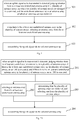
- Fig. 1 is a flow chart illustrating a method for transmitting an uplink signal according to an exemplary embodiment. Referring to Fig, 1 , the method is applied to a terminal and the method includes followings.
- an uplink signal to be transmitted is detected, it is judged whether there is at least one unsheltered antenna array in a plurality of antenna arrays.
- the plurality of antenna arrays are arranged in the terminal.
- the unsheltered antenna array refers to an antenna array of which all antennas are not sheltered.
- an antenna array is selected from the at least one unsheltered antenna array.
- the uplink signal is transmitted via the selected antenna array.
- the uplink signal to be transmitted when the uplink signal to be transmitted is detected, instead of directly selecting an antenna array from the plurality of antenna arrays as the selected antenna array, by judging whether there is the at least one unsheltered antenna array in the plurality of antenna arrays, and by selecting one of the at least one unsheltered antenna array as the selected antenna array, it may avoid a poor quality of transmitting the uplink signal due to a possibility of selecting a sheltered antenna array as the selected antenna array. That is, the quality of transmitting the uplink signal is enhanced.
- the method further includes followings.
- the sheltered antenna array is an antenna array of which one or more antennas are sheltered.
- the number of the one or more antennas sheltered in each of the plurality of antenna is determined.
- an antenna array with a minimum number is selected from the plurality of antenna arrays as the selected antenna array.
- the method further includes followings.
- the uplink signal During a transmission of the uplink signal, it is detected in real time whether there is one or more antennas sheltered in the current selected antenna array for transmitting the uplink signal.
- another antenna array is reselected from the plurality of antenna arrays, instead of the current selected antenna array, to transmit the uplink signal.
- the method further includes following.
- the number of one or more antennas sheltered in the current selected antenna array for transmitting the uplink signal is detected in real time.
- the number of the one or more antennas sheltered in the current selected antenna array for transmitting the uplink signal is greater than a preset threshold
- another antenna array is reselected from the plurality of antenna arrays, instead of the current selected antenna array, to transmit the uplink signal.
- judging whether there is the at least one unsheltered antenna array in the plurality of antenna arrays includes following.
- a sheltered position of the terminal is determined.
- each of the plurality of antenna arrays it is judged whether each of locations of antennas in a corresponding antenna array is same as the sheltered position of the terminal.
- the corresponding antenna array is determined as the unsheltered antenna array.
- determining the sheltered position of the terminal includes followings.
- a location of the first sensor is determined as the sheltered position of the terminal.
- a gesture of the terminal is determined based on a second sensor mounted on the terminal, and the sheltered position is determined based on the gesture of the terminal.
- Fig. 2A is a flow chart illustrating a method for transmitting an uplink signal according to an exemplary embodiment. Referring to Fig. 2A , the method is applied to a terminal and the method includes followings.
- an uplink signal to be transmitted is detected, it is judged by the terminal whether there is at least one unsheltered antenna array in a plurality of antenna arrays.
- an act 202 is executed.
- an act 203 is executed.
- the plurality of antenna arrays arranged in the terminal may be sheltered, a quality of transmitting the uplink signal may be poor via the sheltered antenna arrays. Therefore, it is judged whether there is the at least one unsheltered antenna array in the plurality of antenna arrays when the uplink signal to be transmitted is detected, in order to ensure a high quality of transmitting the uplink signal.
- the terminal may be a phone. Certainly, in practice, the terminal may be another terminal with a capacity of transmitting the uplink signal.
- the uplink signal is to be sent to a base station by the terminal.
- the uplink signal may also be a signal sent by the terminal to another device (e.g. a communication satellite) via an antenna array.
- the unsheltered antenna array refers to an antenna array of which all antennas are not sheltered.
- the sheltered antenna array refers to an antenna array of which at least one antenna is sheltered.
- a sheltered position of the terminal may be determined by the terminal. For each of the plurality of antenna arrays, it is judged whether each of locations of antennas in a corresponding antenna array is same as the sheltered position of the terminal. When the locations of the antennas in the corresponding antenna array are not same as the sheltered position, it is determined that the corresponding antenna array is the unsheltered antenna array. When the location of the one or more antennas in the corresponding antenna array is same as the sheltered position, it is determined that the corresponding antenna array is the sheltered antenna array.
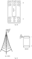
- the two antenna arrays are arranged in the terminal.
- the two antenna arrays are labeled as 1 and 2 respectively.
- the antenna array 1 is arranged at the top of a backside of the terminal.
- the antenna array 1 includes 6 antennas labeled as 11, 12, 13, 14, 15 and 16 respectively.
- the antenna array 2 is arranged at the bottom of the backside of the terminal.
- the antenna array 2 includes 6 antennas labeled as 21, 22, 23, 24, 25 and 26 respectively.
- the sheltered position of the terminal is determined by the terminal and is illustrated as position 1.
- the location of antenna 12 and the location of antenna 15 are same as the position 1. Therefore, it is determined that the antenna 12 and the antenna 15 are the sheltered antennas. It is thus determined that the antenna array 1 is the sheltered antenna array.
- the sheltered position of the terminal may be determined by the terminal in two possible implementations as follows.
- a first possible implementation is described.
- a location of the first sensor is determined as the sheltered position.
- the first sensor is arranged in advance at the locations of the antennas in the antenna array.
- the first sensor may be a pressure sensor, an optical sensor, a temperature sensor and the like.
- the first sensor may be another typed sensor.
- the first sensor may be not arranged at the locations of the antennas in the antenna array, but may be arranged at a boundary of the locations of the antennas in the antenna array, or may be arranged close to the locations of the antennas in the antenna array, in order to directly determine the sheltered position via the first sensor.
- a gesture of the terminal may be determined based on these sensors.
- the gravity sensor or the optical sensor may determine the gesture of the terminal, such as the terminal is placed horizontally and faced upwardly, or the terminal is placed horizontally and faced downwardly, or the terminal is placed vertically, or the like. Therefore, for saving costs and enlarging an application range of the method for transmitting an uplink signal, the gesture of the terminal may be determined based on a second sensor arranged on the terminal. Further, the sheltered position may be determined based on the gesture of the terminal.
- the second sensor may include at least one of the gravity sensor and the optical sensor. Certainly, in practice, the second sensor may include another typed sensor.
- the terminal when the terminal is placed horizontally and faced downwardly, it may be determined that a front side of the terminal is sheltered. When the terminal is placed horizontally and is faced upwardly, it may be determined that the backside of the terminal is sheltered. When the terminal is placed vertically, it is possible that the user is making a call. Generally, it is required to hold the bottom of the terminal by a user's hand when making a call, thus it may be determined that the bottom of the backside of the terminal is sheltered. In practice, according to the gesture of the terminal, other sheltered positions of the terminal may be determined.
- an antenna array is selected by the terminal from the at least one unsheltered antenna array, and act 204 is executed.
- one antenna array may be selected from the at least one unsheltered antenna array by the terminal.
- the terminal may select one of at least one unsheltered antenna array in random as the selected antenna array.
- the terminal may select one of the at least one unsheltered antenna array as the selected antenna array in other manners.
- one possible implementation is to set priorities for the plurality of antenna arrays. When one antenna array is to be selected from the at least one unsheltered antenna array, an antenna array with a highest priority may be selected from the at least one unsheltered antenna array as the selected antenna array according to a respective priority of each antenna array included in the at least one unsheltered antenna array.
- act 203 it is determined by the terminal that the plurality of antenna arrays are sheltered, and an antenna array is selected by the terminal from the plurality of antenna arrays as the selected antenna array. And act 204 is executed.
- an antenna array may be selected from the plurality of antenna arrays as the selected antenna array.
- the number of one or more antennas sheltered in each of the plurality of antenna arrays is different from each other.
- the quality of transmitting the uplink signal via an antenna array with a less number of sheltered antennas is better than that via an antenna array with a more number of sheltered antennas. Therefore, in order to select an optimal antenna array as the selected antenna array, and thus to enhance the quality of transmitting the uplink signal, the number of one or more antennas sheltered in each antenna array may be determined by the terminal, and the antenna array with the minimum number may be selected by the terminal as the selected antenna array.
- the two antenna arrays are arranged in the terminal.
- the two antenna arrays are labeled as 1 and 2 respectively.
- the antenna array 1 and the antenna array 2 are both sheltered. It is determined by the terminal that 3 antennas included in the antenna array 1 are sheltered and 2 antennas included in the antenna array 2 are sheltered.
- the antenna array 1 includes 3 sheltered antennas, while the antenna array 2 includes 2 sheltered antennas. Since the number of sheltered antennas in the antenna array 2 is smaller than that in the antenna array 1, thus the antenna array 2 has the minimum number of the sheltered antennas. Therefore, the antenna array 2 is selected as the selected antenna array by the terminal.
- the uplink signal is transmitted by the terminal via the selected antenna array.
- the selected antenna array is one of the at least one unsheltered antenna array or is the antenna array with the minimum number of sheltered antennas
- the quality of transmitting the uplink signal via the selected antenna array is generally better than that via another antenna array. Therefore, the uplink signal may be transmitted via the selected antenna array.
- the terminal may transmit the uplink signal to the base station in a form of wave beams.
- a gesture of the terminal may be changed.
- the sheltered position of the terminal may be changed. It is thus possible to shelter antennas included in the current selected antenna array for transmitting the uplink signal, thereby weakening the quality of transmitting the uplink signal. Therefore, in order to further ensure the high quality of transmitting the uplink signal, during the transmission of the uplink signal by the terminal, a condition of sheltering the current selected antenna array for transmitting the uplink signal may be detected in real time by the terminal. It may be determined whether another antenna array may be reselected from the plurality of antenna arrays, instead of the current selected antenna array, to transmit the uplink signal, according to the condition of sheltering the current selected antenna array.
- another antenna array may be reselected by the terminal from the plurality of antenna arrays by two possible implementations.
- a first possible implementation is described. For ensuring the high quality of transmitting the uplink signal as possible, during the transmission of the uplink signal by the terminal, it is detected by the device in real time whether there is one or more antennas sheltered in the current selected antenna array for transmitting the uplink signal. When there is the one or more antennas sheltered in the current selected antenna array for transmitting the uplink signal, another antenna array is reselected from the plurality of antenna arrays, instead of the current selected antenna array, to transmit the uplink signal. When there is no antenna sheltered in the current selected antenna array, that is to say, the current selected antenna array is one of the at least one unsheltered antenna array, the uplink signal is continuously transmitted via the current selected antenna array by the terminal. In other words, as long as one antenna included in the current selected antenna array is sheltered, the other antenna array is reselected from the plurality of antenna arrays, as a replacement of the current selected antenna array, to transmit the uplink signal.
- the antenna array 2 is selected from the antenna array 1 and the antenna array 2, instead of the antenna array 1, as the selected antenna array.
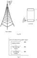
- the uplink signal is transmitted via the antenna array 2 arranged at the bottom of the terminal to the base station, as illustrated in 2D.
- a second possible implementation is described.
- selecting the selected antenna array among the plurality of antenna arrays to transmit the uplink signal may result in a delay of the uplink signal or other risks. As a result, the quality of transmitting the uplink signal is affected. Therefore, during the transmission of the uplink signal by the terminal, the number of one or more antennas sheltered in the current selected antenna array for transmitting the uplink signal is detected by the terminal in real time. When the number is greater than a preset threshold, another antenna array is reselected from the plurality of antenna arrays, instead of the current selected antenna array, to transmit the uplink signal. When the number is smaller than or equal to the preset threshold, the uplink signal may be transmitted continuously via the current selected antenna array by the terminal.
- the current selected antenna array is replaced by the terminal with the other antenna array selected from the plurality of antenna arrays.
- the preset threshold is determined. For example, for determining the preset threshold, one possible strategy is to receive a number value input by a user and to determine the value number as the preset threshold. Certainly, in practice, the preset threshold may be determined by the terminal in other ways. In an example, the preset threshold may be a half of the number of the antennas included in each antenna array. Certainly, in practice, the preset threshold may be others.
- selecting the other antenna array from the plurality of antenna arrays by the terminal may be same with selecting the selected antenna array when the uplink signal to be transmitted is detected illustrated as acts 201 to 203, which is not elaborated herein.
- the current selected antenna array is the antenna array 2, during the transmission of the uplink signal via the antenna array 2, it is detected that the antenna 21 and the antenna 22 included in the antenna array 2 are sheltered.
- the preset threshold is 3, as the number of sheltered antennas in the antenna array is 2 less than 3, the uplink signal is transmitted continuously via the antenna array 2 by the terminal.
- the antenna 25 and the antenna 26 are sheltered, as the number of the sheltered antennas in the antenna array 2 is 4 greater than 3
- the other antenna array (the antenna array 1) is selected by the terminal from the antenna array 1 and the antenna array 2, instead of the antenna array 2, to transmit the uplink signal.
- the uplink signal when it is detected that the uplink signal is to be transmitted, instead of directly selecting an antenna array from the plurality of antenna arrays, by judging whether there is the at least one unsheltered antenna array in the plurality of antenna arrays, and by selecting one of the at least one unsheltered antenna array as the selected antenna array if there is the at least one unsheltered antenna array in the plurality of antenna arrays, it may avoid weakening the quality of transmitting the uplink signal due to a possibility of selecting an sheltered antenna array to transmit the uplink signal. That is, the quality of transmitting the uplink signal is enhanced.
- an antenna array with the minimum number of one or more antennas sheltered may be selected from the plurality of antenna arrays as the selected antenna array to transmit the uplink signal. Therefore, the quality of transmitting the uplink signal is further enhanced. Furthermore, during the transmission of the uplink signal by the terminal, it may be detected by the terminal in real time whether there is one or more antennas sheltered in the current selected antenna array. It may be determined whether to select the other antenna array to transmit the uplink signal according to a sheltered condition of the current selected antenna array, thereby further enhancing the quality of transmitting the uplink signal.
- Fig. 3 is a block diagram illustrating a device for transmitting an uplink signal according to an exemplary embodiment.
- the device includes a judging module 301, a first selecting module 302 and a transmitting module 303.
- the judging module 301 is configured to, when an uplink signal to be transmitted is detected, judge whether there is at least one unsheltered antenna array in a plurality of antenna arrays.
- the plurality of antenna arrays are arranged in a terminal.
- the unsheltered antenna array is an antenna array of which all antennas are not sheltered.
- the first selecting module 302 is configured to, when there is the at least one unsheltered antenna array in the plurality of antenna arrays, select an antenna array from the at least one unsheltered antenna array.
- the transmitting module 303 is configured to transmit the uplink signal via the selected antenna array.
- the device further includes a first determining module, a second determining module and a second selecting module.
- the first determining module is configured to, when there is no the at least one unsheltered antenna array in the plurality of antenna arrays, determine that the plurality of antenna arrays are sheltered.
- the sheltered antenna array is an antenna array of which one or more antennas are sheltered.
- the second determining module is configured to determine the number of the one or more antennas sheltered in each of the plurality of antenna arrays.
- the second selecting module is configured to select an antenna array with a minimum number from the plurality of antenna arrays as the selected antenna array.
- the device further includes a first detecting module and a third selecting module.
- the first detecting module is configured to, during a transmission of the uplink signal, detect in real time whether there is one or more antennas sheltered in the current selected antenna array for transmitting the uplink signal.
- the third selecting module is configured to, when there is the one or more antennas sheltered in the current selected antenna array for transmitting the uplink signal, reselect another antenna array from the plurality of antenna arrays, instead of the current selected antenna array, to transmit the uplink signal.
- the device further includes a second detecting module and a fourth selecting module.
- the second detecting module is configured to, during a transmission of the uplink signal, detect in real time the number of one or more antennas sheltered in the current selected antenna array for transmitting the uplink signal.
- the fourth selecting module is configured to, when the number is greater than a preset threshold, reselect another antenna array from the plurality of antenna arrays, instead of the current selected antenna array, to transmit the uplink signal.
- the judging module further includes a first determining sub-module, a judging sub-module and a second determining sub-module.
- the first determining sub-module is configured to determine a sheltered position of the terminal.
- the judging sub-module is configured to, for each of the plurality of antenna arrays, judge whether each of locations of antennas in a corresponding antenna array is same as the sheltered position.
- the second determining sub-module is configured to, when the locations of the antennas in the corresponding antenna array are not same as the sheltered position, determine the corresponding antenna array as the unsheltered antenna array.
- the first determining sub-module is configured to when it is detected that a first sensor mounted on the terminal is sheltered, determine a location of the first sensor as the sheltered position.
- the first determining sub-module is configured to determine a gesture of the terminal based on a second sensor mounted on the terminal, and determine the sheltered position based on the gesture.
- the uplink signal to be transmitted when the uplink signal to be transmitted is detected, instead of directly selecting an antenna array from the plurality of antenna arrays as the selected antenna array, by judging whether there is the at least one unsheltered antenna array in the plurality of antenna arrays, and by selecting one of the at least one unsheltered antenna as the selected antenna array to transmit the uplink signal, it avoids a poor quality of transmitting the uplink signal due to a possibility of selecting an sheltered antenna array as the selected antenna array. Therefore, the quality of transmitting the uplink signal is enhanced.
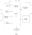
- Fig. 4 is a schematic diagram illustrating an apparatus 400 for transmitting an uplink signal according to an exemplary embodiment.
- the apparatus 400 may be a mobile phone, a messaging device, a tablet device, a Personal Digital Assistant PDA, and the like.
- the apparatus 400 may include the following one or more components: a processing component 402, a memory 404, a power component 406, a multimedia component 408, an audio component 410, an Input/Output (I/O) interface 412, a sensor component 414, and a communication component 416.
- the processing component 402 typically controls overall operations of the apparatus 400, such as the operations associated with display, telephone calls, data communications, camera operations, and recording operations.
- the processing component 402 may include one or more processors 420 to execute instructions to perform all or part of the acts in the above described methods.
- the processing component 402 may include one or more modules which facilitate the interaction between the processing component 402 and other components.
- the processing component 402 may include a multimedia module to facilitate the interaction between the multimedia component 408 and the processing component 402.
- the memory 404 is configured to store various types of data to support the operation of the apparatus 400. Examples of such data include instructions for any applications or methods operated on the apparatus 400, contact data, phonebook data, messages, pictures, video, etc.
- the memory 404 may be implemented using any type of volatile or non-volatile memory devices, or a combination thereof, such as a static random access memory (SRAM), an electrically erasable programmable read-only memory (EEPROM), an erasable programmable read-only memory (EPROM), a programmable read-only memory (PROM), a read-only memory (ROM), a magnetic memory, a flash memory, a magnetic or optical disk.
- SRAM static random access memory
- EEPROM electrically erasable programmable read-only memory
- EPROM erasable programmable read-only memory
- PROM programmable read-only memory
- ROM read-only memory
- magnetic memory a magnetic memory
- flash memory a flash memory
- magnetic or optical disk a magnetic or optical
- the power component 406 provides power to various components of the apparatus 400.
- the power component 406 may include a power management system, one or more power sources, and any other components associated with the generation, management, and distribution of power in the apparatus 400.
- the multimedia component 408 includes a screen providing an output interface between the apparatus 400 and the user.
- the screen may include a liquid crystal display (LCD) and a press panel (TP). If the screen includes the touchable panel, the screen may be implemented as a touch screen to receive input signals from the user.
- the touchable panel includes one or more touch sensors to sense touches, swipes, and other gestures on the touchable panel. The touch sensors may not only sense a boundary of a touch or swipe action, but also sense a duration time and a pressure associated with the touch or swipe action.
- the multimedia component 408 includes a front camera and/or a rear camera. The front camera and/or the rear camera may receive external multimedia data while the apparatus 400 is in an operation mode, such as a photographing mode or a video mode. Each of the front camera and the rear camera may be a fixed optical lens system or have focus and optical zoom capability.
- the audio component 410 is configured to output and/or input audio signals.
- the audio component 410 includes a microphone (MIC) configured to receive an external audio signal when the apparatus 400 is in an operation mode, such as a call mode, a recording mode, and a voice recognition mode.
- the received audio signal may be further stored in the memory 404 or transmitted via the communication component 416.
- the audio component 410 further includes a speaker to output audio signals.
- the I/O interface 412 provides an interface for the processing component 402 and peripheral interface modules, such as a keyboard, a click wheel, buttons, and the like.
- the buttons may include, but are not limited to, a home button, a volume button, a starting button, and a locking button.
- the sensor component 414 includes one or more sensors to provide status assessments of various aspects of the apparatus 400. For instance, the sensor component 414 may detect an open/closed status of the apparatus 400 and relative positioning of components (e.g. the display and the keypad of the apparatus 400). The sensor component 414 may also detect a change in position of the apparatus 400 or of a component in the apparatus 400, a presence or absence of user contact with the 400, an orientation or an acceleration/deceleration of the apparatus 400, and a change in temperature of the apparatus 400.
- the sensor component 414 may include a proximity sensor configured to detect the presence of nearby objects without any physical contact.
- the sensor component 414 may also include a light sensor, such as a CMOS or CCD image sensor, for use in imaging applications. In some embodiments, the sensor component 414 may also include an accelerometer sensor, a gyroscope sensor, a magnetic sensor, a pressure sensor, or a temperature sensor.
- the communication component 416 is configured to facilitate wired or wireless communication between the apparatus 400 and other apparatuses.
- the apparatus 400 can access a wireless network based on a communication standard, such as WIFI, 2G, or 3G, or a combination thereof.
- the communication component 416 receives a broadcast signal or broadcast associated information from an external broadcast management system via a broadcast channel.
- the communication component 416 further includes a near field communication (NFC) module to facilitate short-range communications.
- the NFC module may be implemented based on a radio frequency identification (RFID) technology, an infrared data association (IrDA) technology, an ultra-wideband (UWB) technology, a Bluetooth (BT) technology, and other technologies.
- RFID radio frequency identification
- IrDA infrared data association
- UWB ultra-wideband
- BT Bluetooth
- the apparatus 400 may be implemented with one or more application specific integrated circuits (ASICs), digital signal processors (DSPs), digital signal processing devices (DSPDs), programmable logic devices (PLDs), field programmable gate arrays (FPGAs), controllers, micro-controllers, microprocessors, or other electronic components, for performing the method for transmitting an uplink signal.
- ASICs application specific integrated circuits
- DSPs digital signal processors
- DSPDs digital signal processing devices
- PLDs programmable logic devices
- FPGAs field programmable gate arrays
- controllers micro-controllers, microprocessors, or other electronic components, for performing the method for transmitting an uplink signal.
- non-transitory computer readable storage medium having instructions, such as the memory 404 including instructions.
- the instructions may be executed by the processors 420 of the apparatus 400 to perform the above method for transmitting an uplink signal.
- the non-transitory computer-readable storage medium may be a ROM, a RAM, a CD-ROM, a magnetic tape, a floppy disc, an optical data storage device, and the like.
- Non-transitory computer readable storage medium when instructions stored therein are executed by a processor of a mobile terminal, causing the mobile terminal to perform a method for transmitting an uplink signal.
- the method includes following.
- the unsheltered antenna array is an antenna array of which all antennas are not sheltered.
- an antenna array is selected from the at least one unsheltered antenna array as a selected antenna array.
- the uplink signal is transmitted via the selected antenna array.
- the method further includes followings.
- the sheltered antenna array is an antenna array of which one or more antennas are sheltered.
- the number of the one or more antennas sheltered in each of the plurality of antenna arrays is determined.
- An antenna array with a minimum number is selected from the plurality of antenna arrays as the selected antenna array.
- the method after transmitting the uplink signal via the selected antenna array, the method further includes followings.
- the uplink signal During a transmission of the uplink signal, it is detected in real time whether there is one or more antennas sheltered in the current selected antenna array for transmitting the uplink signal.
- another antenna array is reselected from the plurality of antenna arrays, instead of the current selected antenna array, to transmit the uplink signal.
- the method after transmitting the uplink signal via the selected antenna array, the method further includes followings.
- the number of one or more antennas sheltered in the current selected antenna array is detected in real time.
- another antenna array is reselected from the plurality of antenna arrays, instead of the current selected antenna array, to transmit the uplink signal.
- judging whether there is at least one unsheltered antenna array in a plurality of antenna arrays include at least one unsheltered antenna array includes followings.
- a sheltered position of the terminal is determined.
- each of the plurality of antenna arrays it is judged whether each of locations of antennas in a corresponding antenna array is same as the sheltered position.
- the corresponding antenna array is determined as the unsheltered antenna array.
- determining a sheltered position of the terminal includes followings.
- a location of the first sensor is determined as the sheltered position.
- a gesture of the terminal is determined based on a second sensor mounted on the terminal, and the sheltered position is determined based on the gesture.
- the uplink signal to be transmitted when the uplink signal to be transmitted is detected, instead of directly selecting an antenna array from the plurality of antenna arrays as the selected antenna array, by judging whether there is the at least one unsheltered antenna array in the plurality of antenna arrays, and by selecting one of the at least one unsheltered antenna as the selected antenna array to transmit the uplink signal, it avoids a poor quality of transmitting the uplink signal due to a possibility of selecting an sheltered antenna array as the selected antenna array. Therefore, the quality of transmitting the uplink signal is enhanced.
Landscapes
- Engineering & Computer Science (AREA)
- Computer Networks & Wireless Communication (AREA)
- Signal Processing (AREA)
- Physics & Mathematics (AREA)
- Mathematical Physics (AREA)
- Mobile Radio Communication Systems (AREA)
Applications Claiming Priority (1)
| Application Number | Priority Date | Filing Date | Title |
|---|---|---|---|
| CN201710040962.3A CN108337025B (zh) | 2017-01-20 | 2017-01-20 | 发射上行信号的方法及装置 |
Publications (2)
| Publication Number | Publication Date |
|---|---|
| EP3352383A1 true EP3352383A1 (fr) | 2018-07-25 |
| EP3352383B1 EP3352383B1 (fr) | 2019-12-25 |
Family
ID=61005701
Family Applications (1)
| Application Number | Title | Priority Date | Filing Date |
|---|---|---|---|
| EP18151786.3A Active EP3352383B1 (fr) | 2017-01-20 | 2018-01-16 | Procédé et dispositif de transmission de signaux en liaison montante |
Country Status (6)
| Country | Link |
|---|---|
| EP (1) | EP3352383B1 (fr) |
| JP (1) | JP6559248B2 (fr) |
| KR (1) | KR102126624B1 (fr) |
| CN (1) | CN108337025B (fr) |
| RU (1) | RU2690687C1 (fr) |
| WO (1) | WO2018133341A1 (fr) |
Cited By (1)
| Publication number | Priority date | Publication date | Assignee | Title |
|---|---|---|---|---|
| EP3955472A4 (fr) * | 2019-08-26 | 2022-06-22 | ZTE Corporation | Procédé et dispositif de commande d'antenne 5g, terminal 5g et support d'informations lisible par ordinateur |
Families Citing this family (6)
| Publication number | Priority date | Publication date | Assignee | Title |
|---|---|---|---|---|
| EP3890418A4 (fr) * | 2018-11-29 | 2022-10-19 | Beijing Xiaomi Mobile Software Co., Ltd. | Procédé, appareil et dispositif de détermination de plage de balayage de faisceaux et support de stockage |
| CN109547084B (zh) * | 2019-01-03 | 2023-12-22 | 上海龙旗科技股份有限公司 | 确定目标天线的方法、设备及存储介质 |
| CN112153194B (zh) * | 2020-09-25 | 2022-05-17 | Oppo广东移动通信有限公司 | 电子设备 |
| CN114512828A (zh) * | 2020-11-16 | 2022-05-17 | 华为技术有限公司 | 屏下天线的管理方法及装置 |
| CN113783582A (zh) * | 2021-08-27 | 2021-12-10 | 上海闻泰电子科技有限公司 | 基于毫米波天线的信号传输方法、装置、电子设备和介质 |
| CN116073869A (zh) * | 2021-10-29 | 2023-05-05 | 华为终端有限公司 | 天线的选择方法、终端及介质 |
Citations (2)
| Publication number | Priority date | Publication date | Assignee | Title |
|---|---|---|---|---|
| US9331760B2 (en) * | 2014-05-28 | 2016-05-03 | Qualcomm Incorporated | Method and apparatus for leveraging spatial/location/user interaction sensors to aid in transmit and receive-side beamforming in a directional wireless network |
| AU2016101775A4 (en) * | 2015-10-14 | 2016-11-03 | Apple Inc. | Electronic devices with millimeter wave antennas and metal housings |
Family Cites Families (15)
| Publication number | Priority date | Publication date | Assignee | Title |
|---|---|---|---|---|
| JP3815224B2 (ja) * | 2001-01-26 | 2006-08-30 | 松下電器産業株式会社 | アンテナ装置、それを利用した受信装置、送信装置及び無線端末装置 |
| DE202005022078U1 (de) * | 2004-10-18 | 2013-02-06 | Research In Motion Ltd. | Steuerung einer Vielzahl von internen Antennen in einer mobilen Kommunikationsvorrichtung |
| US7627296B2 (en) * | 2004-10-18 | 2009-12-01 | Research In Motion Limited | Method of controlling a plurality of internal antennas in a mobile communication device |
| WO2008073372A2 (fr) * | 2006-12-11 | 2008-06-19 | Qualcomm Incorporated | Dispositif à antennes multiples pourvu d'un élément d'isolation |
| WO2009029520A1 (fr) * | 2007-08-27 | 2009-03-05 | Rambus Inc. | Antenne-réseau à interconnexion souple pour un dispositif mobile sans fil |
| US8159399B2 (en) * | 2008-06-03 | 2012-04-17 | Apple Inc. | Antenna diversity systems for portable electronic devices |
| JP2011082806A (ja) * | 2009-10-07 | 2011-04-21 | Nec Saitama Ltd | 通信端末 |
| JP5560257B2 (ja) * | 2011-11-24 | 2014-07-23 | 株式会社Nttドコモ | 移動通信端末、移動通信方法及び移動通信プログラム |
| JP6312461B2 (ja) * | 2014-02-26 | 2018-04-18 | シャープ株式会社 | 携帯端末装置 |
| CN104752832B (zh) * | 2015-03-02 | 2018-08-10 | 联想(北京)有限公司 | 一种自对准方法和电子设备 |
| US9641229B2 (en) * | 2015-06-30 | 2017-05-02 | Motorola Mobility Llc | Method and system for a reconfigurable over-indexed antenna array |
| JP6689366B2 (ja) * | 2016-03-30 | 2020-04-28 | シャープ株式会社 | 端末装置 |
| WO2017169010A1 (fr) * | 2016-03-30 | 2017-10-05 | シャープ株式会社 | Dispositif terminal, procédé de communication et programme |
| CN106131329B (zh) * | 2016-06-30 | 2019-08-20 | 维沃移动通信有限公司 | 一种移动终端及移动终端工作模式选择方法 |
| CN109661752A (zh) * | 2016-09-23 | 2019-04-19 | 富士胶片株式会社 | 移动通信终端 |
-
2017
- 2017-01-20 CN CN201710040962.3A patent/CN108337025B/zh not_active Expired - Fee Related
- 2017-07-10 JP JP2017545725A patent/JP6559248B2/ja not_active Expired - Fee Related
- 2017-07-10 RU RU2018126639A patent/RU2690687C1/ru active
- 2017-07-10 KR KR1020187031585A patent/KR102126624B1/ko not_active Expired - Fee Related
- 2017-07-10 WO PCT/CN2017/092418 patent/WO2018133341A1/fr not_active Ceased
-
2018
- 2018-01-16 EP EP18151786.3A patent/EP3352383B1/fr active Active
Patent Citations (2)
| Publication number | Priority date | Publication date | Assignee | Title |
|---|---|---|---|---|
| US9331760B2 (en) * | 2014-05-28 | 2016-05-03 | Qualcomm Incorporated | Method and apparatus for leveraging spatial/location/user interaction sensors to aid in transmit and receive-side beamforming in a directional wireless network |
| AU2016101775A4 (en) * | 2015-10-14 | 2016-11-03 | Apple Inc. | Electronic devices with millimeter wave antennas and metal housings |
Cited By (2)
| Publication number | Priority date | Publication date | Assignee | Title |
|---|---|---|---|---|
| EP3955472A4 (fr) * | 2019-08-26 | 2022-06-22 | ZTE Corporation | Procédé et dispositif de commande d'antenne 5g, terminal 5g et support d'informations lisible par ordinateur |
| US11979210B2 (en) | 2019-08-26 | 2024-05-07 | Xi'an Zhongxing New Software Co., Ltd. | Method and device for controlling 5G antenna, 5G terminal and computer readable storage medium |
Also Published As
| Publication number | Publication date |
|---|---|
| JP6559248B2 (ja) | 2019-08-14 |
| JP2019511134A (ja) | 2019-04-18 |
| RU2690687C1 (ru) | 2019-06-05 |
| CN108337025A (zh) | 2018-07-27 |
| KR20180129890A (ko) | 2018-12-05 |
| WO2018133341A1 (fr) | 2018-07-26 |
| EP3352383B1 (fr) | 2019-12-25 |
| KR102126624B1 (ko) | 2020-06-25 |
| CN108337025B (zh) | 2019-12-27 |
Similar Documents
| Publication | Publication Date | Title |
|---|---|---|
| EP3352383B1 (fr) | Procédé et dispositif de transmission de signaux en liaison montante | |
| EP3813450B1 (fr) | Procédé et appareil pour reconnaître une transmission de liaison descendante | |
| EP3663886B1 (fr) | Procédé et dispositif de commande de véhicule aérien sans pilote, véhicule aérien sans pilote et dispositif de commande à distance | |
| US11641595B2 (en) | Method and apparatus for determining channel occupancy information | |
| EP3322227B1 (fr) | Procédés et appareils de commande de connexion sans fil, programme informatique et support d'enregistrement | |
| US11018741B2 (en) | Wireless communication device and method for switching antenna | |
| US10313936B2 (en) | Method and apparatus for accessing base station | |
| US10318069B2 (en) | Method for controlling state of touch screen, and electronic device and medium for implementing the same | |
| US11596018B2 (en) | Region configuration method and device | |
| US10009283B2 (en) | Method and device for processing information | |
| US20160219424A1 (en) | Methods, apparatuses and devices for transmitting data | |
| US12096474B2 (en) | Method and device for configuring bandwidth part | |
| EP3322167A1 (fr) | Procédé et dispositif de réglage de fréquences d'appareils d'intercom | |
| US20210195574A1 (en) | Communication link configuration method and device | |
| US20230262674A1 (en) | Reception indicating method and apparatus, and reception control method and apparatus | |
| EP3952370B1 (fr) | Appareil et procédé de transmission de données | |
| US20170041377A1 (en) | File transmission method and apparatus, and storage medium | |
| US11496281B2 (en) | Method and device for indicating transmission direction | |
| EP3855658B1 (fr) | Procédé et dispositif de détermination de pucch nécessitant une transmission | |
| US20250151119A1 (en) | Trigger condition determination method and apparatus, and resource partition configuration method and apparatus | |
| US11696276B2 (en) | Data scheduling method and apparatus | |
| EP3771276A1 (fr) | Procédé et dispositif de transmission de données |
Legal Events
| Date | Code | Title | Description |
|---|---|---|---|
| PUAI | Public reference made under article 153(3) epc to a published international application that has entered the european phase |
Free format text: ORIGINAL CODE: 0009012 |
|
| STAA | Information on the status of an ep patent application or granted ep patent |
Free format text: STATUS: THE APPLICATION HAS BEEN PUBLISHED |
|
| AK | Designated contracting states |
Kind code of ref document: A1 Designated state(s): AL AT BE BG CH CY CZ DE DK EE ES FI FR GB GR HR HU IE IS IT LI LT LU LV MC MK MT NL NO PL PT RO RS SE SI SK SM TR |
|
| AX | Request for extension of the european patent |
Extension state: BA ME |
|
| STAA | Information on the status of an ep patent application or granted ep patent |
Free format text: STATUS: REQUEST FOR EXAMINATION WAS MADE |
|
| 17P | Request for examination filed |
Effective date: 20190111 |
|
| RBV | Designated contracting states (corrected) |
Designated state(s): AL AT BE BG CH CY CZ DE DK EE ES FI FR GB GR HR HU IE IS IT LI LT LU LV MC MK MT NL NO PL PT RO RS SE SI SK SM TR |
|
| GRAJ | Information related to disapproval of communication of intention to grant by the applicant or resumption of examination proceedings by the epo deleted |
Free format text: ORIGINAL CODE: EPIDOSDIGR1 |
|
| GRAP | Despatch of communication of intention to grant a patent |
Free format text: ORIGINAL CODE: EPIDOSNIGR1 |
|
| GRAP | Despatch of communication of intention to grant a patent |
Free format text: ORIGINAL CODE: EPIDOSNIGR1 |
|
| STAA | Information on the status of an ep patent application or granted ep patent |
Free format text: STATUS: GRANT OF PATENT IS INTENDED |
|
| INTG | Intention to grant announced |
Effective date: 20190903 |
|
| GRAS | Grant fee paid |
Free format text: ORIGINAL CODE: EPIDOSNIGR3 |
|
| GRAA | (expected) grant |
Free format text: ORIGINAL CODE: 0009210 |
|
| STAA | Information on the status of an ep patent application or granted ep patent |
Free format text: STATUS: THE PATENT HAS BEEN GRANTED |
|
| AK | Designated contracting states |
Kind code of ref document: B1 Designated state(s): AL AT BE BG CH CY CZ DE DK EE ES FI FR GB GR HR HU IE IS IT LI LT LU LV MC MK MT NL NO PL PT RO RS SE SI SK SM TR |
|
| REG | Reference to a national code |
Ref country code: GB Ref legal event code: FG4D |
|
| REG | Reference to a national code |
Ref country code: CH Ref legal event code: EP |
|
| REG | Reference to a national code |
Ref country code: AT Ref legal event code: REF Ref document number: 1218286 Country of ref document: AT Kind code of ref document: T Effective date: 20200115 |
|
| REG | Reference to a national code |
Ref country code: DE Ref legal event code: R096 Ref document number: 602018001693 Country of ref document: DE |
|
| REG | Reference to a national code |
Ref country code: IE Ref legal event code: FG4D |
|
| REG | Reference to a national code |
Ref country code: NL Ref legal event code: MP Effective date: 20191225 |
|
| PG25 | Lapsed in a contracting state [announced via postgrant information from national office to epo] |
Ref country code: LV Free format text: LAPSE BECAUSE OF FAILURE TO SUBMIT A TRANSLATION OF THE DESCRIPTION OR TO PAY THE FEE WITHIN THE PRESCRIBED TIME-LIMIT Effective date: 20191225 Ref country code: NO Free format text: LAPSE BECAUSE OF FAILURE TO SUBMIT A TRANSLATION OF THE DESCRIPTION OR TO PAY THE FEE WITHIN THE PRESCRIBED TIME-LIMIT Effective date: 20200325 Ref country code: GR Free format text: LAPSE BECAUSE OF FAILURE TO SUBMIT A TRANSLATION OF THE DESCRIPTION OR TO PAY THE FEE WITHIN THE PRESCRIBED TIME-LIMIT Effective date: 20200326 Ref country code: LT Free format text: LAPSE BECAUSE OF FAILURE TO SUBMIT A TRANSLATION OF THE DESCRIPTION OR TO PAY THE FEE WITHIN THE PRESCRIBED TIME-LIMIT Effective date: 20191225 Ref country code: BG Free format text: LAPSE BECAUSE OF FAILURE TO SUBMIT A TRANSLATION OF THE DESCRIPTION OR TO PAY THE FEE WITHIN THE PRESCRIBED TIME-LIMIT Effective date: 20200325 Ref country code: SE Free format text: LAPSE BECAUSE OF FAILURE TO SUBMIT A TRANSLATION OF THE DESCRIPTION OR TO PAY THE FEE WITHIN THE PRESCRIBED TIME-LIMIT Effective date: 20191225 Ref country code: FI Free format text: LAPSE BECAUSE OF FAILURE TO SUBMIT A TRANSLATION OF THE DESCRIPTION OR TO PAY THE FEE WITHIN THE PRESCRIBED TIME-LIMIT Effective date: 20191225 |
|
| REG | Reference to a national code |
Ref country code: LT Ref legal event code: MG4D |
|
| PG25 | Lapsed in a contracting state [announced via postgrant information from national office to epo] |
Ref country code: RS Free format text: LAPSE BECAUSE OF FAILURE TO SUBMIT A TRANSLATION OF THE DESCRIPTION OR TO PAY THE FEE WITHIN THE PRESCRIBED TIME-LIMIT Effective date: 20191225 Ref country code: HR Free format text: LAPSE BECAUSE OF FAILURE TO SUBMIT A TRANSLATION OF THE DESCRIPTION OR TO PAY THE FEE WITHIN THE PRESCRIBED TIME-LIMIT Effective date: 20191225 |
|
| PG25 | Lapsed in a contracting state [announced via postgrant information from national office to epo] |
Ref country code: AL Free format text: LAPSE BECAUSE OF FAILURE TO SUBMIT A TRANSLATION OF THE DESCRIPTION OR TO PAY THE FEE WITHIN THE PRESCRIBED TIME-LIMIT Effective date: 20191225 |
|
| PG25 | Lapsed in a contracting state [announced via postgrant information from national office to epo] |
Ref country code: EE Free format text: LAPSE BECAUSE OF FAILURE TO SUBMIT A TRANSLATION OF THE DESCRIPTION OR TO PAY THE FEE WITHIN THE PRESCRIBED TIME-LIMIT Effective date: 20191225 Ref country code: PT Free format text: LAPSE BECAUSE OF FAILURE TO SUBMIT A TRANSLATION OF THE DESCRIPTION OR TO PAY THE FEE WITHIN THE PRESCRIBED TIME-LIMIT Effective date: 20200520 Ref country code: RO Free format text: LAPSE BECAUSE OF FAILURE TO SUBMIT A TRANSLATION OF THE DESCRIPTION OR TO PAY THE FEE WITHIN THE PRESCRIBED TIME-LIMIT Effective date: 20191225 Ref country code: CZ Free format text: LAPSE BECAUSE OF FAILURE TO SUBMIT A TRANSLATION OF THE DESCRIPTION OR TO PAY THE FEE WITHIN THE PRESCRIBED TIME-LIMIT Effective date: 20191225 Ref country code: NL Free format text: LAPSE BECAUSE OF FAILURE TO SUBMIT A TRANSLATION OF THE DESCRIPTION OR TO PAY THE FEE WITHIN THE PRESCRIBED TIME-LIMIT Effective date: 20191225 |
|
| PG25 | Lapsed in a contracting state [announced via postgrant information from national office to epo] |
Ref country code: SM Free format text: LAPSE BECAUSE OF FAILURE TO SUBMIT A TRANSLATION OF THE DESCRIPTION OR TO PAY THE FEE WITHIN THE PRESCRIBED TIME-LIMIT Effective date: 20191225 Ref country code: IS Free format text: LAPSE BECAUSE OF FAILURE TO SUBMIT A TRANSLATION OF THE DESCRIPTION OR TO PAY THE FEE WITHIN THE PRESCRIBED TIME-LIMIT Effective date: 20200425 Ref country code: SK Free format text: LAPSE BECAUSE OF FAILURE TO SUBMIT A TRANSLATION OF THE DESCRIPTION OR TO PAY THE FEE WITHIN THE PRESCRIBED TIME-LIMIT Effective date: 20191225 |
|
| REG | Reference to a national code |
Ref country code: DE Ref legal event code: R097 Ref document number: 602018001693 Country of ref document: DE |
|
| PG25 | Lapsed in a contracting state [announced via postgrant information from national office to epo] |
Ref country code: MC Free format text: LAPSE BECAUSE OF FAILURE TO SUBMIT A TRANSLATION OF THE DESCRIPTION OR TO PAY THE FEE WITHIN THE PRESCRIBED TIME-LIMIT Effective date: 20191225 |
|
| REG | Reference to a national code |
Ref country code: BE Ref legal event code: MM Effective date: 20200131 |
|
| PG25 | Lapsed in a contracting state [announced via postgrant information from national office to epo] |
Ref country code: DK Free format text: LAPSE BECAUSE OF FAILURE TO SUBMIT A TRANSLATION OF THE DESCRIPTION OR TO PAY THE FEE WITHIN THE PRESCRIBED TIME-LIMIT Effective date: 20191225 Ref country code: LU Free format text: LAPSE BECAUSE OF NON-PAYMENT OF DUE FEES Effective date: 20200116 Ref country code: ES Free format text: LAPSE BECAUSE OF FAILURE TO SUBMIT A TRANSLATION OF THE DESCRIPTION OR TO PAY THE FEE WITHIN THE PRESCRIBED TIME-LIMIT Effective date: 20191225 |
|
| PLBE | No opposition filed within time limit |
Free format text: ORIGINAL CODE: 0009261 |
|
| STAA | Information on the status of an ep patent application or granted ep patent |
Free format text: STATUS: NO OPPOSITION FILED WITHIN TIME LIMIT |
|
| REG | Reference to a national code |
Ref country code: AT Ref legal event code: MK05 Ref document number: 1218286 Country of ref document: AT Kind code of ref document: T Effective date: 20191225 |
|
| PG25 | Lapsed in a contracting state [announced via postgrant information from national office to epo] |
Ref country code: BE Free format text: LAPSE BECAUSE OF NON-PAYMENT OF DUE FEES Effective date: 20200131 Ref country code: SI Free format text: LAPSE BECAUSE OF FAILURE TO SUBMIT A TRANSLATION OF THE DESCRIPTION OR TO PAY THE FEE WITHIN THE PRESCRIBED TIME-LIMIT Effective date: 20191225 |
|
| 26N | No opposition filed |
Effective date: 20200928 |
|
| PG25 | Lapsed in a contracting state [announced via postgrant information from national office to epo] |
Ref country code: IT Free format text: LAPSE BECAUSE OF FAILURE TO SUBMIT A TRANSLATION OF THE DESCRIPTION OR TO PAY THE FEE WITHIN THE PRESCRIBED TIME-LIMIT Effective date: 20191225 Ref country code: AT Free format text: LAPSE BECAUSE OF FAILURE TO SUBMIT A TRANSLATION OF THE DESCRIPTION OR TO PAY THE FEE WITHIN THE PRESCRIBED TIME-LIMIT Effective date: 20191225 Ref country code: IE Free format text: LAPSE BECAUSE OF NON-PAYMENT OF DUE FEES Effective date: 20200116 |
|
| PG25 | Lapsed in a contracting state [announced via postgrant information from national office to epo] |
Ref country code: PL Free format text: LAPSE BECAUSE OF FAILURE TO SUBMIT A TRANSLATION OF THE DESCRIPTION OR TO PAY THE FEE WITHIN THE PRESCRIBED TIME-LIMIT Effective date: 20191225 |
|
| REG | Reference to a national code |
Ref country code: CH Ref legal event code: PL |
|
| PG25 | Lapsed in a contracting state [announced via postgrant information from national office to epo] |
Ref country code: CH Free format text: LAPSE BECAUSE OF NON-PAYMENT OF DUE FEES Effective date: 20210131 Ref country code: LI Free format text: LAPSE BECAUSE OF NON-PAYMENT OF DUE FEES Effective date: 20210131 |
|
| PG25 | Lapsed in a contracting state [announced via postgrant information from national office to epo] |
Ref country code: TR Free format text: LAPSE BECAUSE OF FAILURE TO SUBMIT A TRANSLATION OF THE DESCRIPTION OR TO PAY THE FEE WITHIN THE PRESCRIBED TIME-LIMIT Effective date: 20191225 Ref country code: MT Free format text: LAPSE BECAUSE OF FAILURE TO SUBMIT A TRANSLATION OF THE DESCRIPTION OR TO PAY THE FEE WITHIN THE PRESCRIBED TIME-LIMIT Effective date: 20191225 Ref country code: CY Free format text: LAPSE BECAUSE OF FAILURE TO SUBMIT A TRANSLATION OF THE DESCRIPTION OR TO PAY THE FEE WITHIN THE PRESCRIBED TIME-LIMIT Effective date: 20191225 |
|
| PG25 | Lapsed in a contracting state [announced via postgrant information from national office to epo] |
Ref country code: MK Free format text: LAPSE BECAUSE OF FAILURE TO SUBMIT A TRANSLATION OF THE DESCRIPTION OR TO PAY THE FEE WITHIN THE PRESCRIBED TIME-LIMIT Effective date: 20191225 |
|
| P01 | Opt-out of the competence of the unified patent court (upc) registered |
Effective date: 20230523 |
|
| PGFP | Annual fee paid to national office [announced via postgrant information from national office to epo] |
Ref country code: DE Payment date: 20240119 Year of fee payment: 7 Ref country code: GB Payment date: 20240119 Year of fee payment: 7 |
|
| PGFP | Annual fee paid to national office [announced via postgrant information from national office to epo] |
Ref country code: FR Payment date: 20240124 Year of fee payment: 7 |
|
| REG | Reference to a national code |
Ref country code: DE Ref legal event code: R082 Ref document number: 602018001693 Country of ref document: DE Representative=s name: DEHNS GERMANY PARTNERSCHAFT MBB, DE |
|
| REG | Reference to a national code |
Ref country code: DE Ref legal event code: R119 Ref document number: 602018001693 Country of ref document: DE |
|
| GBPC | Gb: european patent ceased through non-payment of renewal fee |
Effective date: 20250116 |
|
| PG25 | Lapsed in a contracting state [announced via postgrant information from national office to epo] |
Ref country code: DE Free format text: LAPSE BECAUSE OF NON-PAYMENT OF DUE FEES Effective date: 20250801 |
|
| PG25 | Lapsed in a contracting state [announced via postgrant information from national office to epo] |
Ref country code: GB Free format text: LAPSE BECAUSE OF NON-PAYMENT OF DUE FEES Effective date: 20250116 |
|
| PG25 | Lapsed in a contracting state [announced via postgrant information from national office to epo] |
Ref country code: FR Free format text: LAPSE BECAUSE OF NON-PAYMENT OF DUE FEES Effective date: 20250131 |