EP3352494B1 - Effizienter uplink-planungsmechanismus für duale konnektivität - Google Patents
Effizienter uplink-planungsmechanismus für duale konnektivität Download PDFInfo
- Publication number
- EP3352494B1 EP3352494B1 EP18161898.4A EP18161898A EP3352494B1 EP 3352494 B1 EP3352494 B1 EP 3352494B1 EP 18161898 A EP18161898 A EP 18161898A EP 3352494 B1 EP3352494 B1 EP 3352494B1
- Authority
- EP
- European Patent Office
- Prior art keywords
- base station
- pdcp
- data
- buffer occupancy
- mobile node
- Prior art date
- Legal status (The legal status is an assumption and is not a legal conclusion. Google has not performed a legal analysis and makes no representation as to the accuracy of the status listed.)
- Active
Links
Images






Classifications
-
- H—ELECTRICITY
- H04—ELECTRIC COMMUNICATION TECHNIQUE
- H04W—WIRELESS COMMUNICATION NETWORKS
- H04W16/00—Network planning, e.g. coverage or traffic planning tools; Network deployment, e.g. resource partitioning or cells structures
- H04W16/24—Cell structures
- H04W16/32—Hierarchical cell structures
-
- H—ELECTRICITY
- H04—ELECTRIC COMMUNICATION TECHNIQUE
- H04W—WIRELESS COMMUNICATION NETWORKS
- H04W28/00—Network traffic management; Network resource management
- H04W28/02—Traffic management, e.g. flow control or congestion control
- H04W28/0278—Traffic management, e.g. flow control or congestion control using buffer status reports
-
- H—ELECTRICITY
- H04—ELECTRIC COMMUNICATION TECHNIQUE
- H04W—WIRELESS COMMUNICATION NETWORKS
- H04W28/00—Network traffic management; Network resource management
- H04W28/02—Traffic management, e.g. flow control or congestion control
- H04W28/08—Load balancing or load distribution
- H04W28/082—Load balancing or load distribution among bearers or channels
-
- H—ELECTRICITY
- H04—ELECTRIC COMMUNICATION TECHNIQUE
- H04W—WIRELESS COMMUNICATION NETWORKS
- H04W72/00—Local resource management
- H04W72/20—Control channels or signalling for resource management
- H04W72/21—Control channels or signalling for resource management in the uplink direction of a wireless link, i.e. towards the network
-
- H—ELECTRICITY
- H04—ELECTRIC COMMUNICATION TECHNIQUE
- H04W—WIRELESS COMMUNICATION NETWORKS
- H04W76/00—Connection management
- H04W76/10—Connection setup
- H04W76/15—Setup of multiple wireless link connections
-
- H—ELECTRICITY
- H04—ELECTRIC COMMUNICATION TECHNIQUE
- H04W—WIRELESS COMMUNICATION NETWORKS
- H04W80/00—Wireless network protocols or protocol adaptations to wireless operation
- H04W80/02—Data link layer protocols
-
- H—ELECTRICITY
- H04—ELECTRIC COMMUNICATION TECHNIQUE
- H04W—WIRELESS COMMUNICATION NETWORKS
- H04W80/00—Wireless network protocols or protocol adaptations to wireless operation
- H04W80/06—Transport layer protocols, e.g. TCP [Transport Control Protocol] over wireless
-
- H—ELECTRICITY
- H04—ELECTRIC COMMUNICATION TECHNIQUE
- H04W—WIRELESS COMMUNICATION NETWORKS
- H04W84/00—Network topologies
- H04W84/02—Hierarchically pre-organised networks, e.g. paging networks, cellular networks, WLAN [Wireless Local Area Network] or WLL [Wireless Local Loop]
- H04W84/04—Large scale networks; Deep hierarchical networks
- H04W84/042—Public Land Mobile systems, e.g. cellular systems
- H04W84/045—Public Land Mobile systems, e.g. cellular systems using private Base Stations, e.g. femto Base Stations, home Node B
Definitions
- the present disclosure relates to methods for communication between a mobile station and a base station.
- it relates to an improved method for managing resource allocation for a mobile station, preferably for a mobile station capable of simultaneously connecting to more than one cell.
- the present disclosure is also providing the mobile station for participating in the methods described herein.
- LTE Long Term Evolution
- LTE Long Term Evolution
- LTE Long-Term Evolution
- UTRA Evolved UMTS Terrestrial Radio Access
- UTRAN UMTS Terrestrial Radio Access Network
- the LTE system represents efficient packet based radio access and radio access networks that provide full IP-based functionalities with low latency and low cost.
- scalable multiple transmission bandwidths are specified such as 1.4, 3.0, 5.0, 10.0, 15.0, and 20.0 MHz, in order to achieve flexible system deployment using a given spectrum.
- Orthogonal Frequency Division Multiplexing OFDM
- OFDM Orthogonal Frequency Division Multiplexing
- SC-FDMA Single-carrier frequency division multiple access
- UE user equipment
- MIMO multiple-input multiple-output
- the E-UTRAN consists of eNBs, providing the E-UTRA user plane (PDCP/RLC/MAC/PHY) and control plane (RRC) protocol terminations towards the UE.
- the eNB hosts the Physical (PHY), Medium Access Control (MAC), Radio Link Control (RLC), and Packet data Control Protocol (PDCP) layers that include the functionality of user-plane header-compression and encryption. It also offers Radio Resource Control (RRC) functionality corresponding to the control plane.
- RRC Radio Resource Control
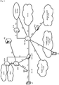
- the eNBs are interconnected with each other by means of the X2 interface.
- the eNBs are also connected by means of the S1 interface to the EPC (Evolved Packet Core), more specifically to the MME (Mobility Management Entity) by means of the S1-MME and to the Serving Gateway (S-GW) by means of the S1-U.
- EPC Evolved Packet Core
- MME Mobility Management Entity
- S-GW Serving Gateway
- the SGW routes and forwards user data packets, while also acting as the mobility anchor for the user plane during inter-eNB handovers and as the anchor for mobility between LTE and other 3GPP technologies (terminating S4 interface and relaying the traffic between 2G/3G systems and PDN GW).
- the SGW terminates the DL data path and triggers paging when DL data arrives for the UE. It manages and stores UE contexts, e.g. parameters of the IP bearer service, network internal routing information. It also performs replication of the user traffic in case of lawful interception.
- the MME is the key control-node for the LTE access-network. It is responsible for idle mode UE tracking and paging procedure including retransmissions. It is involved in the bearer activation/deactivation process and is also responsible for choosing the SGW for a UE at the initial attach and at time of intra-LTE handover involving Core Network (CN) node relocation. It is responsible for authenticating the user (by interacting with the HSS).
- NAS Non-Access Stratum
- the Non-Access Stratum (NAS) signaling terminates at the MME and it is also responsible for generation and allocation of temporary identities to UEs. It checks the authorization of the UE to camp on the service provider's Public Land Mobile Network (PLMN) and enforces UE roaming restrictions.
- PLMN Public Land Mobile Network
- the MME is the termination point in the network for ciphering/integrity protection for NAS signaling and handles the security key management. Lawful interception of signaling is also supported by the MME.
- the MME also provides the control plane function for mobility between LTE and 2G/3G access networks with the S3 interface terminating at the MME from the SGSN.
- the MME also terminates the S6a interface towards the home HSS for roaming UEs
- the downlink component carrier of a 3GPP LTE system is subdivided in the time-frequency domain in so-called subframes.
- each subframe is divided into two downlink slots as shown in Figure 3 , wherein the first downlink slot comprises the control channel region (PDCCH region) within the first OFDM symbols.
- Each subframe consists of a give number of OFDM symbols in the time domain (12 or 14 OFDM symbols in 3GPP LTE (Release 8)), wherein each OFDM symbol spans over the entire bandwidth of the component carrier.
- the OFDM symbols thus each consists of a number of modulation symbols transmitted on respective N DL RB ⁇ N RB sc subcarriers as also shown in Figure 4 .
- a physical resource block is defined as N DL symb consecutive OFDM symbols in the time domain (e.g. 7 OFDM symbols) and N RB sc consecutive subcarriers in the frequency domain as exemplified in Figure4 (e.g. 12 subcarriers for a component carrier).
- a physical resource block thus consists of N DL symb ⁇ N RB sc resource elements, corresponding to one slot in the time domain and 180 kHz in the frequency domain (for further details on the downlink resource grid, see for example 3GPP TS 36.211, "Evolved Universal Terrestrial Radio Access (E-UTRA); Physical Channels and Modulation (Release 8)", section 6.2, available at http://www.3gpp.org ).
- One subframe consists of two slots, so that there are 14 OFDM symbols in a subframe when a so-called "normal” CP (cyclic prefix) is used, and 12 OFDM symbols in a subframe when a so-called “extended” CP is used.
- a "resource block pair” or equivalent "RB pair” or "PRB pair”.
- component carrier refers to a combination of several resource blocks in the frequency domain.
- cell refers to a combination of downlink and optionally uplink resources.
- the linking between the carrier frequency of the downlink resources and the carrier frequency of the uplink resources is indicated in the system information transmitted on the downlink resources. Similar assumptions for the component carrier structure apply to later releases too.
- FIG. 4 provides a brief overview of the OSI model on which the further discussion of the LTE architecture is based.
- the Open Systems Interconnection Reference Model (OSI Model or OSI Reference Model) is a layered abstract description for communication and computer network protocol design.
- the OSI model divides the functions of a system into a series of layers. Each layer has the property that it only uses the functions of the layer below, and only exports functionality to the layer above.
- a system that implements protocol behavior consisting of a series of these layers is known as a 'protocol stack' or 'stack'. Its main feature is in the junction between layers which dictates the specifications on how one layer interacts with another. This means that a layer written by one manufacturer can operate with a layer from another. For the purposes of the present disclosure, only the first three layers will be described in more detail below.
- the physical layer or layer 1 main purpose is the transfer of information (bits) over a specific physical medium (e.g. coaxial cables, twisted pairs, optical fibers, air interface, etc.). It converts or modulates data into signals (or symbols) that are transmitted over a communication channel.
- a specific physical medium e.g. coaxial cables, twisted pairs, optical fibers, air interface, etc.
- the purpose of the data link layer is to shape the information flow in a way compatible with the specific physical layer by breaking up the input data into data frames (Segmentation And Re-assembly (SAR) functions). Furthermore, it may detect and correct potential transmission errors by requesting a retransmission of a lost frame. It typically provides an addressing mechanism and may offer flow control algorithms in order to align the data rate with the receiver capacity. If a shared medium is concurrently used by multiple transmitters and receivers, the data link layer typically offers mechanisms to regulate and control access to the physical medium.
- SAR Segmentation And Re-assembly
- the data link layer is often subdivided into sublayers (e.g. RLC and MAC sublayers in UMTS).
- Typical examples of Layer 2 protocols are PPP/HDLC, ATM, frame relay for fixed line networks and RLC, LLC or MAC for wireless systems. More detailed information on the sublayers PDCP, RLC and MAC of layer 2 is given later.
- the network layer or Layer 3 provides the functional and procedural means for transferring variable length packets from a source to a destination via one or more networks while maintaining the quality of service requested by the transport layer.
- the network layer's main purposes are inter alia to perform network routing, network fragmentation and congestion control functions.
- the main examples of network layer protocols are the IP Internet Protocol or X.25.
- Layers 4 to 7 it should be noted that depending on the application and service it is sometimes difficult to attribute an application or service to a specific layer of the OSI model since applications and services operating above Layer 3 often implement a variety of functions that are to be attributed to different layers of the OSI model. Therefore, especially in TCP(UDP)/IP based networks, Layer 4 and above is sometimes combined and forms a so-called "application layer".
- SDU service data unit
- PDU protocol data unit
- a PDU is generally formed by a payload part consisting of the processed version of the received SDU(s) preceded by a layer N specific header and optionally terminated by a trailer. Since there is no direct physical connection (except for Layer 1) between these peer processes, a PDU is forwarded to the layer N-1 for processing. Therefore, a layer N PDU is from a layer N-1 point of view an SDU.
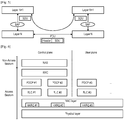
- the LTE layer 2 user-plane/control-plane protocol stack comprises three sublayers as shown in Figure 6 , PDCP, RLC and MAC.
- each layer receives a SDU from a higher layer for which the layer provides a service and outputs a PDU to the layer below.
- the RLC layer receives packets from the PDCP layer. These packets are called PDCP PDUs from a PDCP point of view and represent RLC SDUs from an RLC point of view.
- the RLC layer creates packets which are provided to the layer below, i.e. the MAC layer.
- the packets provided by RLC to the MAC layer are RLC PDUs from an RLC point of view and MAC SDUs from a MAC point of view.
- the link-layer protocols enhance the service to upper layers by increased reliability, security and integrity.
- the link layer is responsible for the multi-user medium access and scheduling.
- IP Internet Protocol
- VoIP voice over IP
- TCP Transmission Control Protocol
- TCP file downloads perform better over links with low bandwidth-delay products. Consequently, downloads at very high data rates (e.g., 100 Mb/s) require even lower delays and, in addition, are more sensitive to IP packet losses than VoIP traffic.
- the Packet data Convergence Protocol (PDCP) sublayer is responsible mainly for IP header compression and ciphering. In addition, it supports lossless mobility in case of inter-eNB handovers and provides integrity protection to higher layer-control protocols.
- PDCP Packet data Convergence Protocol
- the radio link control (RLC) sublayer comprises mainly ARQ functionality and supports data segmentation and concatenation. The latter two minimize the protocol overhead independent of the data rate.
- the medium access control (MAC) sublayer provides HARQ and is responsible for the functionality that is required for medium access, such as scheduling operation and random access.
- Figure 7 exemplary depicts the data flow of an IP packet through the link-layer protocols down to the physical layer. The Figure shows that each protocol sublayer adds its own protocol header to the data units.
- PDCP Packet data Convergence Protocol
- the PDCP layer processes Radio Resource Control (RRC) messages in the control plane and IP packets in the user plane.
- RRC Radio Resource Control
- IP packets in the user plane.
- RRC Radio Resource Control
- AM, UM, TM the main functions performed by a PDCP entity of the PDCP layer are:
- the PDCP layer manages data streams in the user plane, as well as in the control plane, only for the radio bearers using either a Dedicated Control Channel (DCCH) or a Dedicated Transport Channel (DTCH).
- DCCH Dedicated Control Channel
- DTCH Dedicated Transport Channel
- the architecture of the PDCP layer differs for user plane data and control plane data.
- Two different types of PDCP PDUs are defined in LTE: PDCP data PDUs and PDCP Control PDUs.
- PDCP data PDUs are used for both control and user plane data.
- PDCP Control PDUs are only used to transport the feedback information for header compression, and for PDCP status reports which are used in case of handover and hence are only used within the user plane.
- the Buffer Status reporting procedure is used to provide the serving eNB with information about the amount of data available for transmission in the UL buffers of the UE.
- RRC controls BSR reporting by configuring the two timers periodicBSR-Timer and retxBSR-Timer and by, for each logical channel, optionally signalling logicalChannelGroup which allocates the logical channel to an LCG.
- the UE shall consider all radio bearers which are not suspended and may consider radio bearers which are suspended.
- a Buffer Status Report shall be triggered if any of the following events occur:
- a MAC PDU shall contain at most one MAC BSR control element, even when multiple events trigger a BSR by the time a BSR can be transmitted in which case the Regular BSR and the Periodic BSR shall have precedence over the padding BSR.
- the UE shall restart retxBSR-Timer upon indication of a grant for transmission of new data on any UL-SCH.
- All triggered BSRs shall be cancelled in case the UL grant(s) in this subframe can accommodate all pending data available for transmission but is not sufficient to additionally accommodate the BSR MAC control element plus its subheader. All triggered BSRs shall be cancelled when a BSR is included in a MAC PDU for transmission.
- the UE shall transmit at most one Regular/Periodic BSR in a TTI. If the UE is requested to transmit multiple MAC PDUs in a TTI, it may include a padding BSR in any of the MAC PDUs which do not contain a Regular/Periodic BSR.
- All BSRs transmitted in a TTI always reflect the buffer status after all MAC PDUs have been built for this TTI.
- Each LCG shall report at the most one buffer status value per TTI and this value shall be reported in all BSRs reporting buffer status for this LCG.
- a Padding BSR is not allowed to cancel a triggered Regular/Periodic BSR.
- a Padding BSR is triggered for a specific MAC PDU only and the trigger is cancelled when this MAC PDU has been built.
- the Logical Channel Prioritization (LCP) procedure is applied when a new transmission is performed.
- RRC controls the scheduling of uplink data by signalling for each logical channel:
- the UE shall maintain a variable Bj for each logical channel j.
- Bj shall be initialized to zero when the related logical channel is established, and incremented by the product PBR x TTI duration for each TTI, where PBR is Prioritized Bit Rate of logical channel j.
- PBR Prioritized Bit Rate of logical channel j.
- the value of Bj can never exceed the bucket size and if the value of Bj is larger than the bucket size of logical channel j, it shall be set to the bucket size.
- the bucket size of a logical channel is equal to PBR x BSD, where PBR and BSD are configured by upper layers.
- the UE shall perform the following Logical Channel Prioritization procedure when a new transmission is performed:
- the UE shall not transmit data for a logical channel corresponding to a radio bearer that is suspended (the conditions for when a radio bearer is considered suspended are defined in TS 36.331 ).
- the UE shall take into account the following relative priority in decreasing order:
- steps 1 to 3 and the associated rules may be applied either to each grant independently or to the sum of the capacities of the grants. Also the order in which the grants are processed is left up to UE implementation. It is up to the UE implementation to decide in which MAC PDU a MAC control element is included when UE is requested to transmit multiple MAC PDUs in one TTI.
- the frequency spectrum for IMT-Advanced was decided at the World Radio communication Conference 2007 (WRC-07 ). Although the overall frequency spectrum for IMT-Advanced was decided, the actual available frequency bandwidth is different according to each region or country. Following the decision on the available frequency spectrum outline, however, standardization of a radio interface started in the 3rd Generation Partnership Project (3GPP). At the 3GPP TSG RAN #39 meeting, the study item description on "Further Advancements for E-UTRA (LTE-Advanced)" was approved in the 3GPP . The study item covers technology components to be considered for the evolution of E-UTRA, e.g. to fulfill the requirements on IMT-Advanced.
- 3GPP 3rd Generation Partnership Project
- network densification can be achieved by the deployment of complementary low-power nodes respectively small cells under the coverage of an existing macro-node layer.
- the low-power nodes provide very high traffic capacity and very high user throughput locally, for example in indoor and outdoor hotspot positions.
- the macro layer ensures service availability and QoE over the entire coverage area.
- the layer containing the low-power nodes can also be referred to as providing local-area access, in contrast to the wide-area-covering macro layer.
- the installation of low-power nodes respectively small cells as well as heterogeneous deployments has been possible since the first release of LTE.
- a number of solutions have been specified in recent releases of LTE (i.e., Release 10/11). More specifically, these releases introduced additional tools to handle inter-layer interference in heterogeneous deployments.
- small cells require further enhancements and in many cases need to interact with or complement existing macrocells.
- Mobility performance achieved by small cell deployments should be comparable with that of a macro only network.
- any new solutions should not result in excessive increase of signalling load towards the CN.
- additional signalling and user plane traffic load caused by small cell enhancements should also be taken into account.
- the finite radio resource should be allocated and used carefully among the UEs and radio bearers.
- the eNB is the focal point through which all downlink data flows before being transmitted over the radio interface to each UE. Thus, the eNB can make consistent decisions about which downlink data should be transmitted first.
- each UE makes an individual decision based only on the data in its own buffers and the allocated radio resource.
- the Logical Channel Prioritization (LCP) procedure is introduced.
- the LCP procedure is used for MAC PDU construction by deciding the amount of data from each logical channel and the type of MAC Control Element that should be included in the MAC PDU. By using the LCP procedure, the UE can satisfy the QoS of each radio bearer in the best and most predictable way.
- the simplest and most intuitive method is the absolute priority-based method, where the MAC PDU space is allocated to logical channels in decreasing order of logical channel priority. This is, data from the highest priority logical channel are served first in the MAC PDU, followed by data from the next highest priority logical channel, continuing until the MAC PDU space runs out.
- the absolute priority-based method is quite simple in terms of UE implementation, it sometimes leads to starvation of data from low-priority logical channels. Starvation means that the data from the low-priority logical channels cannot be transmitted because the data from high-priority logical channels take up all the MAC PDU space.
- a Prioritized Bit Rate (PBR) is defined for each logical channel, in order to transmit data in order of importance but also to avoid starvation of data with lower priority.
- the PBR is the minimum data rate guaranteed for the logical channel. Even if the logical channel has low priority, at least a small amount of MAC PDU space is allocated to guarantee the PBR. Thus, the starvation problem can be avoided by using the PBR.
- Constructing a MAC PDU with PBR consists of two rounds.
- each logical channel is served in decreasing order of logical channel priority, but the amount of data from each logical channel included in the MAC PDU is initially limited to the amount corresponding to the configured PBR value of the logical channel.
- the second round is performed.
- each logical channel is served again in decreasing order of priority.
- the major difference for the second round compared to the first round is that each logical channel of lower priority can be allocated with MAC PDU space only if all logical channels of higher priority have no more data to transmit.
- a MAC PDU may include not only the MAC SDUs from each configured logical channel but also the MAC CE. Except for a Padding BSR, the MAC CE has a higher priority than a MAC SDU from the logical channels because it controls the operation of the MAC layer. Thus, when a MAC PDU is composed, the MAC CE, if it exists, is the first to be included and the remaining space is used for MAC SDUs from the logical channels. Then, if additional space is left and it is large enough to include a BSR, a Padding BSR is triggered and included in the MAC PDU.
- the table below shows the priority order considered when generating a MAC PDU.
- the C-RNTI MAC CE and data from the UL-CCCH have the highest priority.
- the C-RNTI MAC CE and data from the UL-CCCH are never included in the same MAC PDU.
- data from the UL-CCCH have higher priority than other MAC CEs.
- the UL-CCCH transports an RRC message using SRB0, UL-CCCH data must have higher priority than other data.
- data from the UL-CCCH are transported during the RA procedure and the size of a MAC PDU from the UL-CCCH is limited.
- the C-RNTI MAC CE is used during the RA procedure by a UE whose existence is known by the eNB. Since the RA procedure is subject to collision, it is important to have a means by which the eNB can identify each UE. Thus, the UE is required to include its C-RNTI as its identity as early as possible during the RA procedure.
- each channel is served up to the data amount equivalent to the PBR according to the order of priority.
- a channel without any configured PBR value is not served.
- the channel is served up to the data amount that is available in the buffer.
- each channel is allocated space in the MAC PDU up to its configured value of PBR.
- a logical channel is served only when the following three conditions are met:
- channel 1 is served first. Because the remaining data in the buffer for channel 1 are larger than the remaining space in the MAC PDU, all the remaining space in the MAC PDU is allocated to channel 1. Because there is no more space, channels 2 and 3 are not served in the second round.
- Each MAC SDU corresponds to one RLC PDU and one RLC PDU includes at least 1 byte of RLC PDU header.
- For each MAC SDU there exists a corresponding at least 1 byte MAC subheader.
- the overall overhead caused by the MAC subheader and the RLC PDU header of every logical channel in a MAC PDU would be huge.
- the token-bucket model with PBR is applied.
- each logical channel is associated with two parameters: bucketSizeDuration and prioritizedBitRate.
- bucketSizeDuration and prioritizedBitRate.
- each logical channel is given a right to transmit a prioritizedBitRate amount of data in every subframe. If a certain logical channel has not fully used the right to transmit its prioritizedBitRate amount of data in a certain subframe, the remaining right can be used in another subframe.
- the right to transmit can be accumulated up to a (prioritizedBitRate x bucketSizeDuration) amount of data.
- the right to transmit is decreased by the amount of data included in the MAC PDU.
- the parameter bucketSizeDuration sets the limit up to which a logical channel can accumulate the right to transmit.
- logical channel prioritization is provided.
- bucketSizeDuration was 4 ms (subframes) and prioritizedBitRate was 1 Kb/ms.
- the logical channel cannot accumulate more than 4 Kb worth of right to transmit.
- the maximum number of bits that the logical channel can transmit is 4 Kb.
- the logical channel has not transmitted any data for the 1 st subframe to the 5th subframe. But, because of the limited size of the token bucket, the maximum token accumulated by the logical channel at the 5th subframe is 4 Kb.
- dual connectivity is used to refer to an operation where a given UE consumes radio resources provided by at least two different network nodes connected with non-ideal backhaul.
- UE is connected with both macro cell (macro eNB) and small cell (secondary eNB).
- macro eNB macro cell
- secondary eNB small cell
- each eNB involved in dual connectivity for a UE may assume different roles. Those roles do not necessarily depend on the eNB's power class and can vary among UEs.
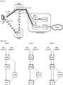
- Figure 9 shows some exemplary architecture for dual connectivity. It should be only understood as one potential option. However the present disclosure is not limited to this specific network/protocol architecture but can be applied generally. Following assumptions on the architecture are made here:
- SeNB is connected directly with the S-GW, i.e. S1-U is between S-GW and SeNB.
- S1-U is between S-GW and SeNB.
- Figure 10 depicts those three options taking the downlink direction for the U-plane data as an example.
- Option 2 is assumed throughout the description and also shown in the Figure.
- a common problem of any wireless communication system is that resources are limited and it is not possible to allocate and use all the resources all the time since there is more than one potential seeker of these resources.
- the Downlink (DL) is however different from the Uplink (UL).
- the eNB has the complete view of the requirements of all the UEs and their bearer(s). Namely, how much data is to be transmitted to each UE for each of their bearers, what is the radio condition (and therefore which resources are good/bad), QoS etc.
- UL the network does not know how much data the UE has sent on each of its UL bearers. So, it cannot allocate a precise amount of resources for each of the UL bearer of this UE.
- BSR Buffer Status Report
- LCP Logical Channel Prioritization
- architecture option 2C This is, for instance, the situation in architecture option 2 e.g. 2C which is shown in Figure 13 .
- architecture option 2C the air-interface transmission of a particular bearer is completely via a particular cell; in the diagram of Figure 13 , the left bearer transmission is via MeNB physical resources, and the right bearer transmission is via the SeNB physical resources.
- the corresponding UE side picture of the Protocol Stack is shown in Figure 14 .
- the MACs in Cell 1 and 2 do not know how much grant they should allocate for the shared (dashed) bearer since there is no defined rule so far. Therefore, as per today, if these MAC Schedulers strictly run the LCP, then they may end up over-allocating a grant (for instance, each allocating grant to the radio bearer equals to 'prioritisedBitRate') to the dashed bearer which now would receive grants twice.
- the buffer Status reporting procedure is used to provide the serving eNB with information about the amount of data available for transmission in the UL buffers of the UE.
- the amount of data available for transmission is the sum of data available for transmission in PDCP and data available for transmission in RLC entity (the details of which are publicly available in 3GPP documents TS 36.322 and 36.323 ).
- the PDCP is a common entity, the Individual RLC entities of the split-dashed-bearer (i.e. RLC of MeNB and RLC of SeNB) derive their SDUs from. Therefore, following the present specification the data available for transmission may double-count the same PDCP SDUs and PDCP PDUs not yet submitted to RLC, one for each MAC entity or cell.
- 3GPP draft document by RENESAS MOBILE EUROPE titled "On protocol stack impacts of dual connectivity" 3GPP TSG-RAN WG2 Meeting #83, R2-132405 , discloses protocol stack impacts of dual connectivity and some analysis from the RAN2 viewpoint about the user plane protocol architecture for dual connectivity.
- 3GPP Technical Specification Group Radio Access Network "Study on Small Cell Enhancements for E-UTRA and E-UTRAN - Higher layer aspects" 3GPP TR 36.842 V0.3.0 covers higher layer technologies to be considered for enhanced support of small cell deployments in E-UTRA and E-UTRAN.
- INTERDIGITAL COMMUNICATIONS "User Plane Architecture for Dual-Connectivity", 3GPP TSG-RAN WG2 Meeting #81 bis, R2-131327 , discusses the pros/cons of the alternatives possible for the termination of a PDCP layer and evaluates the applicability of these alternatives.
- NTT DOCOMO, INC "Discussion for U-plane architecture for dual connectivity"
- 3GPP TSG-RAN WG2 #81, R2-130324 addresses U-plane architecture and the protocol stack for dual connectivity.
- EP 2 568 759 discloses a method and an apparatus for transmitting a buffer status report in a wireless network, where a user equipment is configured with a plurality of component carriers.
- the user equipment obtains an amount of data to be transmitted after respective media access layer protocol data units corresponding to the respective component carriers are generated, generates the uplink buffer status report message according to the amount of data to be transmitted, and reports the uplink buffer status report message to a base station serving the user equipment.
- RENESAS MOBILE EUROPE "User plane detailed related to the SCE user plane architecture selection", 3GPP TSG-RAN WG2 Meeting #83bis, R2-133310 , discloses user plane details related to the SCE user plane architecture selection which are related to functions that may change when there are simultaneous connections to more than one eNB.
- One non-limiting and exemplary embodiment of the present disclosure provides a communication method for a mobile node connectable to a master base station and to a secondary base station by using a split bearer split across the master base station and the secondary base station.
- a Packet Data Convergence Protocol, PDCP, layer located in the mobile node is shared for the split bearer between the master base station and the secondary base station.
- the mobile node splits a total buffer occupancy of the PDCP layer in the mobile node between the master base station and the secondary base station based on a split ratio, into a first PDCP buffer occupancy value for the master base station and a second PDCP buffer occupancy value for the secondary base station.
- the mobile node generates a first buffer status report for the master base station based on the first PDCP buffer occupancy value, and further also generates a second buffer status report for the secondary base station based on the second PDCP buffer occupancy value. Subsequently, the mobile node transmits the first buffer status report to the master base station, and transmits the second buffer status report to the secondary base station.
- a particular split ratio is defined such that one of the first and second PDCP buffer occupancy values is equal to the total buffer occupancy of the PDCP layer in the mobile node for the split bearer, and such that the other one of the first and second PDCP buffer occupancy values is equal to zero.
- said particular split ratio is expressed by 1 to 0 or 0 to 1.
- the mobile node when being configured with the particular split ratio, transmit all uplink data, processed by the PDCP layer, to either the master base station or the secondary base station depending on the particular split ratio, with the exception of RLC uplink data being transmitted to the respective base station.
- the mobile node when being configured with the particular split ratio, deactivates the split bearer for uplink data, processed by the PDCP layer, to either the master base station or the secondary base station depending on the particular split ratio.
- the mobile node is informed by the master base station about how to split the total buffer occupancy of the PDCP layer in the mobile node between the master base station and the secondary base station. Preferably this may be done by a flag in an information element associated with the split bearer.
- a first Radio Link Control, RLC layer is located in the mobile node for the split bearer to the master base station
- a second RLC layer is located in the mobile node for the split bearer to the secondary base station.
- the first buffer status report is generated by the mobile node based on the sum of the first PDCP buffer occupancy value and a buffer occupancy value of the first RLC layer in the mobile node.
- the second buffer status report is generated by the mobile node based on the sum of the second PDCP buffer occupancy value and a buffer occupancy value of the second RLC layer in the mobile node.
- a particular split ratio is defined such that one of the first and second PDCP buffer occupancy values is equal to the total buffer occupancy of the PDCP layer in the mobile node for the split bearer, and such that the other one of the first and second PDCP buffer occupancy values is equal to zero. Furthermore, in case the first respectively second buffer status report is zero, the first respectively second buffer status report is not transmitted.
- the mobile node is configured to transmit all the acknowledgements of the Transmission Control Protocol, TCP, layer, relating to TCP downlink data received in the mobile node, to the master base station. This is preferably done independent from whether or not the remaining uplink data is transmitted by the mobile node to the master base station.
- TCP Transmission Control Protocol
- the PDCP layer of the mobile node detects TCP acknowledgments and internally forwards the detected TCP acknowledgements to lower layers to be transmitted via a channel to the master base station.
- the calculation of the first buffer status report considers the transmission of all the acknowledgements of the TCP layer to the master base station, irrespective of the split ratio.
- the mobile node performs a first Logical Channel Prioritization, LCP, procedure for the split bearer to the master base station, based on the value of the buffer occupancy for the split bearer to the master base station reported with the first buffer status report.
- LCP Logical Channel Prioritization
- the mobile node performs a second Logical Channel Prioritization, LCP, procedure for the split bearer to the secondary base station, based on the value of the buffer occupancy for the split bearer to the secondary base station reported with the second buffer status report.
- the value of the buffer occupancy reported with the first buffer status report is considered in the first LCP procedure by serving resources to the split bearer to the master base station as a maximum up to the value of the buffer occupancy reported with the first buffer status report for the split bearer to the master base station.
- the value of the buffer occupancy reported with the second buffer status report is considered in the second LCP procedure by serving resources to the split bearer to the secondary base station as a maximum up to the value of the buffer occupancy reported with the second buffer status report for the split bearer to the secondary base station.
- a first Media Access Control, MAC, layer is located in the mobile node for the split bearer to the master base station, and a second MAC layer is located in the mobile node for the split bearer to the secondary base station.
- the first MAC layer triggers the buffer status reporting in the second MAC layer for the split bearer.
- the second MAC layer triggers the buffer status reporting in the first MAC layer for the split bearer.
- the first buffer status report is generated by the first MAC layer at the time of being triggered, and the second buffer status report is generated by the second MAC layer at the time of being triggered.
- the first buffer status report is generated by the first MAC layer at the time the first buffer status report is scheduled to be transmitted to the master base station, and the second buffer status report is generated by the second MAC layer at the time the first buffer status report is scheduled to be transmitted to the master base station.
- the first buffer status report is generated by the first MAC layer at the time the first buffer status report is scheduled to be transmitted to the master base station, and the second buffer status report is generated by the second MAC layer at the time the second buffer status report is scheduled to be transmitted to the secondary base station.
- the first buffer status report is generated by the first MAC layer at the time the first buffer status report is scheduled to be transmitted to the master base station or at the time the first buffer status report is triggered at the first MAC layer
- the second buffer status report is generated by the second MAC layer at the time the second buffer status report is scheduled to be transmitted to the secondary base station, wherein the second buffer status report includes the value of the data not reported by the first buffer status report.
- a first Media Access Control, MAC, layer is located in the mobile node for the split bearer to the master base station, and a second MAC layer is located in the mobile node for the split bearer to the secondary base station.
- Buffer status reporting is triggered in the first MAC layer due to data arrival in the buffer of the split bearer.
- Buffer status reporting is triggered in the second MAC layer due to data arrival in the buffer of the split bearer.
- the embodiment further provides a mobile node connectable to a master base station and to a secondary base station by using a split bearer split across the master base station and the secondary base station.
- a Packet Data Convergence Protocol, PDCP, layer located in the mobile node is shared for the split bearer between the master base station and the secondary base station.
- a processor of the mobile node splits a total buffer occupancy of the PDCP layer in the mobile node between the master base station and the secondary base station, based on a split ratio, into a first PDCP buffer occupancy value for the master base station and a second PDCP buffer occupancy value for the secondary base station.
- the processor generates a first buffer status report for the master base station based on the first PDCP buffer occupancy value, and generates a second buffer status report for the secondary base station based on the second PDCP buffer occupancy value.
- a transmitter of the mobile node transmits the first buffer status report to the master base station, and transmitting the second buffer status report to the secondary base station.
- An embodiment of the present disclosure provides a communication method for a mobile node connectable to a master base station and to a secondary base station by using a logical channel shared by the master base station and the secondary base station.
- a Packet Data Convergence Protocol, PDCP, layer is located in the mobile node and shared for the shared logical channel between the master base station and the secondary base station.
- the mobile node splits a total buffer occupancy of the PDCP layer in the mobile node between the master base station and the secondary base station based on a split-buffer ratio, into a first PDCP buffer occupancy value for the master base station and a second PDCP buffer occupancy value for the secondary base station.
- the mobile node generates a first buffer status report for the master base station based on the first PDCP buffer occupancy value, and generates a second buffer status report for the secondary base station based on the second PDCP buffer occupancy value.
- the mobile node transmits the first buffer status report to the master base station, and transmits the second buffer status report to the secondary base station.
- the split-buffer ratio is determined by the master base station, preferably based on at least one of: a load handled by the Secondary Base Station, offload requirements, channel conditions, quality of service.
- the determined split-buffer ratio is transmitted from the master base station to the mobile node and/or the secondary base station, preferably using Radio Resource Control, RRC, signalling, or Media Access Control, MAC, signalling.
- the split-buffer ratio is determined by the mobile node, preferably based on at least one of: radio thresholds of the radio links between the mobile node and respectively the master and secondary base station, past resource grants received by the mobile node.
- the determined split-buffer ratio is transmitted from the mobile node to the master base station and/or the secondary base station, preferably using Radio Resource Control, RRC, signalling, or Media Access Control, MAC, signalling.
- a first Radio Link Control, RLC layer is located in the mobile node for the shared logical channel to the master base station, and a second RLC layer is located in the mobile node for the shared logical channel to the secondary base station.
- the first buffer status report is generated by the mobile node based on the sum of the first PDCP buffer occupancy value and a buffer occupancy value of the first RLC layer in the mobile node.
- the second buffer status report is generated by the mobile node based on the sum of the second PDCP buffer occupancy value and a buffer occupancy value of the second RLC layer in the mobile node.
- the mobile node is connectable to the master base station and to the secondary base station by using a plurality of logical channels shared between the master base station and the secondary base station.
- the split-buffer ratio is applied to only one or a set of logical channels out of the plurality of shared logical channels, or the split-buffer ratio is applied to all of the plurality of shared logical channels.
- the mobile node transmits the first buffer status report for the master base station to the secondary base station, preferably for the secondary base station to estimate the amount of resources the mobile station might be allocated in the next few subframes from the master base station.
- the mobile node transmits the second buffer status report for the secondary base station to the master base station, preferably for the master base station to estimate the amount of resources the mobile station might be allocated in the next few subframes from the secondary base station.
- An embodiment of the present disclosure provides further a mobile node connectable to a master base station and to a secondary base station by using a logical channel shared by the master base station and the secondary base station.
- a Packet Data Convergence Protocol, PDCP, layer located in the mobile node is shared for the shared logical channel between the master base station and the secondary base station.
- a processor of the mobile node splits a total buffer occupancy of the PDCP layer in the mobile node between the master base station and the secondary base station, based on a split-bearer buffer ratio, into a first PDCP buffer occupancy value for the master base station and a second PDCP buffer occupancy value for the secondary base station.
- a processor of the mobile node generates a first buffer status report for the master base station based on the first PDCP buffer occupancy value, and generates a second buffer status report for the secondary base station based on the second PDCP buffer occupancy value.
- a transmitter of the mobile node transmits the first buffer status report to the master base station, and transmits the second buffer status report to the secondary base station.
- a receiver of the mobile node receives from the master base station the split-buffer ratio, determined by the master base station, preferably using Radio Resource Control, RRC, signalling, or Media Access Control, MAC, signalling.
- RRC Radio Resource Control
- MAC Media Access Control
- the split-buffer ratio is determined by the mobile node, preferably based on at least one of: radio thresholds of the radio links between the mobile node and respectively the master and secondary base station, past resource grants received by the mobile node.
- the transmitter transmits the determined split-buffer ratio to the master base station and/or the secondary base station, preferably using Radio Resource Control, RRC, signalling, or Media Access Control, MAC, signalling.
- a first Radio Link Control, RLC layer is located in the mobile node for the shared logical channel to the master base station, and a second RLC layer is located in the mobile node for the shared logical channel to the secondary base station.
- the processor generates the first buffer status report based on the sum of the first PDCP buffer occupancy value and a buffer occupancy value of the first RLC layer in the mobile node.
- the processor generates the second buffer status report based on the sum of the second PDCP buffer occupancy value and a buffer occupancy value of the second RLC layer in the mobile node.
- the processor determines whether the total buffer occupancy of the PDCP layer and the RLC layer in the mobile node exceeds a pre-determined threshold or not. If yes, the steps of splitting the total buffer occupancy, generating and transmitting the first and second buffer status reports are performed. If no, the steps of splitting the total buffer occupancy, generating and transmitting the first and second buffer status reports are not performed, and the mobile node generates and transmits its uplink data buffer status report to only one of the master or secondary base station.
- An embodiment of the present disclosure provides further a master base station for use in a mobile communication system, where a mobile node is connected to the master base station and to a secondary base station by using a logical channel shared by the master base station and the secondary base station.
- a Packet Data Convergence Protocol, PDCP, layer located in the mobile node is shared for the shared logical channel between the master base station and the secondary base station.
- a processor of the master base station determines a split-buffer ratio, preferably based on at least one of: a load handled by the Secondary Base Station, offload requirements, channel conditions, quality of service.
- the split-buffer ratio is for use by the mobile node to split a total buffer occupancy of the PDCP layer in the mobile node between the master base station and the secondary base station based on the split-buffer ratio, into a first PDCP buffer occupancy value for the master base station and a second PDCP buffer occupancy value for the secondary base station.
- a transmitter transmits the determined split-buffer ratio to the mobile node and/or the secondary base station, preferably using Radio Resource Control, RRC, signalling, or Media Access Control, MAC, signalling.
- a further embodiment of the present disclosure provides a method for a mobile node connectable to a master base station and to a secondary base station by using a logical channel shared by the master base station and the secondary base station.
- a Packet Data Convergence Protocol, PDCP, layer located in the mobile node is shared for the shared logical channel between the master base station and the secondary base station.
- a first Radio Link Control, RLC layer is located in the mobile node for the shared logical channel to the master base station, and a second RLC layer is located in the mobile node for the shared logical channel to the secondary base station.
- the mobile node transmits a total buffer occupancy value of the PDCP layer in the mobile node, a buffer occupancy value of the first RLC layer and a buffer occupancy value of the second RLC layer, to the master base station and/or the secondary base station.
- Either the master base station or the secondary base station determine a split ratio, based on the received total buffer occupancy value of the PDCP layer in the mobile node, the buffer occupancy value of the first RLC layer and the buffer occupancy value of the second RLC layer. The determined split ratio is transmitted to the other one of the master base station and the secondary base station.
- the master base station and secondary base station perform the uplink resource allocation for the shared logical channel, respectively based on the split ratio, such that the uplink resource allocation for the shared logical channel for the data as indicated by the received total occupancy value of the PDCP layer is split between the master base station and the secondary base station according to the split ratio.
- the master base station configures the shared logical channel to be alone within a logical channel group.
- the mobile node determines to which base station to transmit the total buffer occupancy value of the PDCP layer in the mobile node, the buffer occupancy value of the first RLC layer and the buffer occupancy value of the second RLC layer, preferably based on at least one of:
- the mobile node determines to which base station to transmit the total buffer occupancy value of the PDCP layer in the mobile node, the buffer occupancy value of the first RLC layer and the buffer occupancy value of the second RLC layer.
- the further embodiment of the present disclosure provides a mobile node connectable to a master base station and to a secondary base station by using a logical channel shared by the master base station and the secondary base station.
- a Packet Data Convergence Protocol, PDCP, layer located in the mobile node is shared for the shared logical channel between the master base station and the secondary base station.
- a first Radio Link Control, RLC layer is located in the mobile node for the shared logical channel to the master base station, and a second RLC layer is located in the mobile node for the shared logical channel to the secondary base station.
- a transmitter of the mobile node transmits a total buffer occupancy value of the PDCP layer in the mobile node, a buffer occupancy value of the first RLC layer and a buffer occupancy value of the second RLC layer, to the master base station and the secondary base station, for the master or secondary base station to determine a split ratio, based on which the uplink resource allocation for the shared logical channel is respectively performed by the master and secondary base station, such that the uplink resource allocation for the shared logical channel for the data as indicated by the received total occupancy value of the PDCP layer is split between the master base station and the secondary base station according to the split ratio.
- the further embodiment of the present disclosure provides a master base station for use in a mobile communication system, wherein a mobile node is connectable to the master base station and to a secondary base station by using a logical channel shared by the master base station and the secondary base station.
- a Packet Data Convergence Protocol, PDCP, layer located in the mobile node is shared for the shared logical channel between the master base station and the secondary base station.
- a first Radio Link Control, RLC layer is located in the mobile node for the shared logical channel to the master base station, and a second RLC layer is located in the mobile node for the shared logical channel to the secondary base station.
- a receiver of the master base station receives from the mobile node a total buffer occupancy value of the PDCP layer in the mobile node, a buffer occupancy value of the first RLC layer and a buffer occupancy value of the second RLC layer.
- a processor of the master base station determines a split ratio, based on the received total buffer occupancy value of the PDCP layer in the mobile node, the buffer occupancy value of the first RLC layer and the buffer occupancy value of the second RLC layer.
- a transmitter of the master base station transmits the determined split ratio to the secondary base station.
- the processor performs the uplink resource allocation for the shared logical channel, based on the split ratio, such that the uplink resource allocation for the shared logical channel for the data as indicated by the received total occupancy value of the PDCP layer is split between the master base station and the secondary base station according to the split ratio.
- a still further embodiment of the present disclosure provides a communication method for a mobile node connectable to a master base station and to a secondary base station by using a logical channel shared by the master base station and the secondary base station.
- a Packet Data Convergence Protocol, PDCP, layer located in the mobile node is shared for the shared logical channel between the master base station and the secondary base station.
- a prioritized bitrate parameter used for a logical channel prioritization, LCP, procedure is split into a first prioritized bitrate parameter for the LCP, procedure for the shared logical channel to the master base station, and into a second prioritized bitrate parameter for the LCP procedure for the shared logical to the secondary base station,
- the mobile node performs a first LCP procedure for the shared logical channel to the master base station, based on the first prioritized bitrate parameter.
- the mobile node performs a second LCP procedure for the shared logical channel to the secondary base station, based on the second prioritized bitrate parameter.
- the first LCP procedure is performed by a Media Access Control, MAC, entity in the mobile node responsible for the master base station, and the LCP procedure is performed by a MAC entity in the mobile node responsible for the secondary base station.
- MAC Media Access Control
- the still further embodiment of the present disclosure provides a mobile node connectable to a master base station and to a secondary base station by using a logical channel shared by the master base station and the secondary base station.
- a Packet Data Convergence Protocol, PDCP, layer located in the mobile node is shared for the shared logical channel between the master base station and the secondary base station.
- a processor of the mobile node splits a prioritized bitrate parameter used for a logical channel prioritization, LCP, procedure, into a first prioritized bitrate parameter for the LCP, procedure for the shared logical channel to the master base station, and into a second prioritized bitrate parameter for the LCP procedure for the shared logical to the secondary base station.
- the processor performs a first LCP procedure for the shared logical channel to the master base station, based on the first prioritized bitrate parameter, and performs a second LCP procedure for the shared logical channel to the secondary base station, based on the second prioritized bitrate parameter.
- Another embodiment of the present disclosure provides a communication method for a mobile node connectable to a master base station and to a secondary base station by using a logical channel shared by the master base station and the secondary base station.
- a Packet Data Convergence Protocol, PDCP, layer located in the mobile node is shared for the shared logical channel between the master base station and the secondary base station.
- the mobile node performs a first logical channel prioritization, LCP, procedure, for the shared logical channel to either the master base station or to the secondary base station, based on a prioritized bitrate parameter, including updating the prioritized bitrate parameter by the mobile node based on the first LCP procedure.
- LCP logical channel prioritization
- the mobile node After finishing the first LCP procedure by the mobile node, the mobile node performs a second LCP procedure of the shared logical channel to the other base station, secondary base station or master base station, based on the updated prioritized bitrate parameter.
- the mobile node determines whether the first LCP procedure for the shared logical channel is either to the master base station or to the secondary base station, according to one of the following:
- the steps of performing the first and second LCP procedures are performed by the mobile node every transmission time interval.
- This another embodiment further provides a mobile node connectable to a master base station and to a secondary base station by using a logical channel shared by the master base station and the secondary base station.
- a Packet Data Convergence Protocol, PDCP, layer located in the mobile node is shared for the shared logical channel between the master base station and the secondary base station.
- a processor of the mobile node performs a first logical channel prioritization, LCP, procedure, for the shared logical channel to either the master base station or to the secondary base station, based on a prioritized bitrate parameter, including updating the prioritized bitrate parameter by the mobile node based on the first LCP procedure.
- the processor performs, after finishing the first LCP procedure, a second LCP procedure of the shared logical channel to the other base station, secondary base station or master base station, based on the updated prioritized bitrate parameter.
- the steps of performing the first and second LCP procedures are performed by the processor of the mobile node every transmission time interval.
- a still another embodiment of the present disclosure provides a communication method for a mobile node connectable to a master base station and to a secondary base station by using a logical channel shared by the master base station and the secondary base station.
- a Packet Data Convergence Protocol, PDCP, layer located in the mobile node is shared for the shared logical channel between the master base station and the secondary base station.
- a first Media Access Control, MAC, entity in the mobile node is responsible to perform logical channel prioritization, LCP, procedures regarding the master base station.
- a second MAC entity in the mobile node is responsible to perform LCP procedure regarding the secondary base station.
- One of the first or second MAC entity in the mobile node performs a first LCP procedure for the shared logical channel, during a particular first number of transmission time intervals.
- the other one of the first or second MAC entity in the mobile node performs a second LCP procedure for the shared logical channel, during a particular second number of transmission time intervals.
- the other one of the first or second MAC entity performs a third LCP procedure for other logical channels than the shared logical channel, during the first number of transmission time intervals.
- the one of the first or second MAC entity performs a fourth LCP procedure for other logical channels than the shared logical channel, during the second number of transmission time intervals.
- This embodiment further provides a mobile node connectable to a master base station and to a secondary base station by using a logical channel shared by the master base station and the secondary base station.
- a Packet Data Convergence Protocol, PDCP, layer located in the mobile node is shared for the shared logical channel between the master base station and the secondary base station.
- a first Media Access Control, MAC, entity in the mobile node is responsible to perform logical channel prioritization, LCP, procedures regarding the master base station.
- a second MAC entity in the mobile node is responsible to perform LCP procedure regarding the secondary base station.
- a processor of the mobile node performs via the one of the first or second MAC entity in the mobile node a first LCP procedure for the shared logical channel, during a particular first number of transmission time intervals.
- the processor performs, after performing the first LCP procedure during the particular first number of transmission time intervals, via the other one of the first or second MAC entity, a second LCP procedure for the shared logical channel, during a particular second number of transmission time intervals.
- the processor performs via the other one of the first or second MAC entity a third LCP procedure for other logical channels than the shared logical channel, during the first number of transmission time intervals.
- the processor performs via one of the first or second MAC entity a fourth LCP procedure for other logical channels than the shared logical channel, during the second number of transmission time intervals.
- a further embodiment of the present disclosure provides a communication method for a mobile node connectable to a master base station and to a secondary base station by using a logical channel shared by the master base station and the secondary base station.
- a Packet Data Convergence Protocol, PDCP, layer located in the mobile node is shared for the shared logical channel between the master base station and the secondary base station.
- the master base station determines a first resource allocation for the mobile node with respect to the plurality of logical channels of the master base station, including the shared logical channel, and transmitting same to the mobile node.
- the secondary base station determines a second resource allocation for the mobile node with respect to the plurality of logical channels of the secondary base station, including the shared logical channel, and transmitting same to the mobile node.
- the mobile node determines the amount of unsatisfied prioritized bitrate or of remaining buffer for each of the plurality of logical channels, except for the shared logical channel, based on the first and second resource allocations.
- the mobile node re-allocates resources from either the received first or the received second resource allocation regarding to the shared logical channel, to the logical channels having an unsatisfied prioritized bitrate or remaining buffer in a logical channel order where the logical channel with the highest unsatisfied prioritized bitrate is first.
- the further embodiment also provides a mobile node connectable to a master base station and to a secondary base station by using a logical channel shared by the master base station and the secondary base station.
- a Packet Data Convergence Protocol, PDCP, layer located in the mobile node is shared for the shared logical channel between the master base station and the secondary base station.
- a receiver of the mobile node receives from the master base station a first resource allocation for the mobile node with respect to the plurality of logical channels of the master base station, including the shared logical channel.
- the receiver receives from the secondary base station a second resource allocation for the mobile node with respect to the plurality of logical channels of the secondary base station, including the shared logical channel.
- a processor of the mobile node determines the amount of unsatisfied prioritized bitrate or of remaining buffer for each of the plurality of logical channels, except for the shared logical channel, based on the first and second resource allocations.
- the processor re-allocates resources from either the received first or the received second resource allocation regarding to the shared logical channel, to the logical channels having an unsatisfied prioritized bitrate or remaining buffer, in a logical channel order where the logical channel with the highest unsatisfied prioritized bitrate is first.
- the present disclosure provides several embodiments with regard to an improved buffer status reporting and logical channel prioritization procedure.
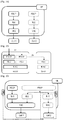
- Figure 15 schematically illustrates an S1-U interface terminating in MeNB, in addition to a radio bearer split in the MeNB, as well as independent RLCs for the split radio bearers.
- Figure 17 schematically shows that in the UP architecture options 3C and 3D, the PDCP is a common entity for the RLC, MAC and PHY layers for the MeNB and SeNB.
- the BSR will be considered first.
- User plane architecture option Series 3 being considered in 3GPP, in particular in 3GPP document TR 36.842 , allows a bearer split such that packets from a particular bearer(s) can be received/transmitted via more than one cell simultaneously from/to the UE.
- different UL activities e.g. LCP, BSR, PHR and others can be linked so that, once the UE knows e.g. how the BSR for the split bearer has to be reported to each link/cell, it can also derive how the PBR derivation shall be done for running LCP for this split bearer correspondingly in each MAC entity towards the individual participating cell(s) or vice versa.
- This can be further linked to PHR such that a specific PHR trigger may also trigger the BSR/PBR etc. re-derivation/re-computation and even reporting in that sense a corresponding new trigger.
- a fixed ratio which can be semi-statically used (until re-derived/re-configured) to derive for example the BSR and the LCP parameters like the PBR.
- the ratio could be semi-statically fixed (hereafter called 'fixed') until changed later upon a fresh derivation/signalling of the same.
- FIG. 18 An example thereof is illustrated in Figure 18 .
- LC2 Logical Channel 2
- MeNB Logical Channel 2
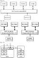
- Figure 18 schematically illustrates a UE side picture.
- the BSR for only those channels are reported inside an LCG that are actually received/transmitted between the corresponding pair of MeNB-UE or SeNB-UE.
- there are two MAC entities in the UE namely MAC-MeNB and MAC-SeNB, that calculate the buffer size corresponding to their part of the logical channels.
- LC2 is the Split Bearer whose packets are transmitted/received via both the MeNB and SeNB.
- Calculation of the Buffer Status Report adds the BO for all logical channels.
- BO for each Logical Channel is RLC Buffer + PDCP Buffer.
- the RLC BO Buffer Occupancy
- PDCP buffer is shared/split between the corresponding MACs only if the related logical channel is split, otherwise not.
- BSR to be reported to MeNB by MAC-MeNB is a simple sum of PDCP BO for LC1 (100 Bytes) + RLC BO for LC1 (10 Bytes), and therefore, MAC-MeNB calculates the buffer size corresponding to the logical Channel LC1 as 110 Bytes. Since LCG1 for MAC-MeNB is only consisting of LC1 (LC4 also belonging to LCG1 refers to SeNB), the Buffer Status reported to MeNB (by MAC-MeNB) for LCG1 is 110 Bytes.
- the Buffer Status Report is the sum of PDCP BO + RLC BO
- the corresponding BSR adds the RLC BOs to this value. Therefore, MAC-MeNB calculates the buffer size corresponding to the logical Channels LCG2 as 99 Bytes, namely 76 + 11 + 12 Bytes.
- 1:4 is only taken as an exemplary ratio; could be represented also as 1/5:4/5 or 0.2:0.8.
- the UE should report a buffer occupancy of 40 Bytes to the MeNB and 60 Bytes to the SeNB.
- this ratio is based primarily on how much traffic the network wants to offload to the Small Cell (e.g. 10%, 50%, 99% or 100%).
- the PDCP BO gets split accordingly.
- the PDCP BO to be reported to the MeNB by MAC-MeNB is 0 bytes.
- the PDCP BO of 60 bytes for logical channel LC3 is added, and in this case completely due to not being a split bearer.
- PDCP BO for group LCG2 to be reported to the MeNB is 60 bytes.
- the corresponding RLC BOs for group LCG2 are to be added; this adds another 11 bytes and 12 bytes for logical channels LC2 and LC3 respectively.
- the full PDCP buffer for the split bearer is reported.
- the 80 bytes in the PDCP buffer for LC2 are added completely to the RLC BO of 14 bytes for LC2.
- the complete BSR reports a total value 94 bytes (80+14).
- the particular split ratios of 1:0 and 0:1 have the advantage of a simplified UE behaviour with respect to the BSR procedure for the split bearer cases.
- buffer status reports are actually only reported when the value of the BSR is not zero.
- the BSR basically reports the BO for the RLC layer, i.e. RLC BO reflecting the status of the received RLC PDUs in the downlink, to the SeNB.
- the corresponding BSR that would be computed would have the value 0. Consequently, according to an advantageous embodiment, these kind of BSR which would report a value of 0 shall not be transmitted.
- the fixed ratio can, for example, be derived by the network and signalled to the UE.
- the MeNB is in charge of defining the ratio value, for instance by taking input such as the SeNB load factor from SeNB as well.
- the eNB could signal the ratio value to the UE using RRC Signalling (e.g. while (re)-Configuring a Bearer) or using MAC Signalling.
- This ratio can tell the UE what fraction of the buffer needs to be reported to each of the participating cells for a particular split-bearer or, alternatively, to all the split-bearers, therefore it can be implemented by using only one ratio per UE.
- the network nodes MeNB and SeNB can share this allocated ratio information so that eNBs not only know how much UL grant will be provided to the UE by the other eNB, for instance in the next few TTIs. This can give an indication of the resource/UL power usage of the other link, and then each link may provide its resource/UL power usage accordingly.
- the network can signal how to split the total buffer occupancy of the PDCP layer in different ways, as will be explained in the following.
- the network may already indicate in the bearer configuration, which link should be used for the BSR reporting for PDCP data as explained above. This may be done e.g. by a Radio Resource Control (RRC) message e.g. by a radio resource configuration message.
- RRC Radio Resource Control
- a flag may be introduced for a logical channel associated to a split EPS bearer. The flag is thus indicating whether the UE should report PDCP data in the buffer within a BSR for this logical channel or not.
- the flag may be included in the logicalChannelConfig information element, defined in the standard TS36.331, in a smilar way as the logicalChannelSR-Mask Information Element (IE).
- IE logicalChannelSR-Mask Information Element
- the definition of the "data becoming available" in the technical standards TS 36.323, TS36.322 and TS 36.321 can be reused in said respect, such that the PDCP data shall only be considered for the BSR reporting and optionally also for BSR triggering as "data becoming available" when the flag is set.
- This flag would basically indicate which of the two logical channels for a split bearer is used for BSR reporting of PDCP data.
- One of the two logical channels either the one used for transmissions towards the MeNB or the one towards the SeNB, would be enabled for BSR reporting of PDCP data, whereas the other one would be disabled (or suspended) for BSR reporting of PDCP data.
- a new information element may be specified in either the MAC-MainConfig IE or DRB-ToAddMod IE (already standardized in TS36.331), thus indicating whether the PDCP data of a split bearer shall be considered by a specific radio bearer or logical channel for BSR reporting or not.
- MAC Control elements like BSR or PHR which are also transmitted in the uplink are not radio bearer specific data and hence are not in the scope of this present disclosure.
- the ratio could be based on some specific criteria like cell load of participating cell, offloading requirements, such as how much traffic needs to be offloaded to SeNB, UE's UL channel conditions, such as which link is better/worse, QoS factors such as packet delay/bearer latency requirements, etc.
- the BSR allocation may only apply to the buffer occupancy in the PDCP sub-layer, as in 3GPP document TS 36.323 , but not e.g. to RLC sub-layer which may be reported "as-is" i.e. without any further splitting between the MeNB and SeNB.
- the above ratio-based splitting may be subject to some "Certain Minimum Traffic/buffer" which may be configured to the UE or specified.
- the certain minimum range will be configurable i.e. when the network configures a bearer to the UE using an RRC Connection Reconfiguration message; it may say that up to Index 20 of Table 6.1.3.1-1: Buffer size levels for BSR (as described in 3GPP TS 36.321-a40) is considered as below certain minimum range.
- the UE may rather send its UL data to only one of the link; the link itself could be based on UE's choice or could be pre-configured together with the minimum traffic/buffer occupancy.
- the bearer type e.g. signalling or specific data bearer like streaming, background etc.
- the choice of link/bearer itself could be pre-configured/specified or based on UE's implementation choice.
- any acknowledgements of the TCP layer associated with TCP downlink data received in the UE are always to be transmitted to the MeNB. This is independent from whether the TCP ACKs refer to data received via the SeNB, and/or independent from whether or not other uplink data is transmitted by the mobile node to the MeNB or SeNB.
- TCP acknowledgements are transmitted in the uplink for each TCP downlink data packet received by the UE.
- TCP acknowledgements are processed as exemplified in Fig. 7 , thus being encapsulated in the IP layer and further by the PDCP layer as a PDCP PDU etc.
- the UE In order to force all TCP ACKs to be transmitted to the MeNB, the UE must detect these TCP ACKs (or at least those TCP ACKs that would otherwise be transmitted to the SeNB) and forward them over the appropriate logical channel to the MeNB (instead of to the SeNB). This may be achieved by the UE according to different implementations, some of which will be explained in the following.
- inter-layer notification(s) may be defined between the TCP and the PDCP layers, thus allowing the PDCP layer to identify the TCP ACKs and forward them to the appropriate RLC entity for further processing and transmission to the MeNB.
- the PDCP layer may detect the TCP ACKs directly, i.e. without any inter-layer notification from the above layers, based e.g. on some implementation rules. For instance, usually TCP ACKs have a fixed PDCP PDU size, and may thus be distinguished from other PDCP PDUs.
- the TCP/IP header identifies the data to relate to a TCP ACK.
- These detection procedures may be performed by the PDCP layer before IP header compression.
- the UE shall be able to direct all the TCP ACKs to the appropriate lower layers, for transmission to the MeNB.
- the TCP performance is directly related to the RTT (Round Trip Time) / delay.
- RTT und Trip Time
- this particular embodiment where all TCP ACKs are to transmitted to the MeNB may be used in combination with any of the embodiments relating to the split ratio when calculating the BSR and when deactivating uplink transmission of PDCP data for a split bearer to one of the MeNB and SeNB.
- the split bearer to the MeNB is deactivated (i.e. all traffic shall be offloaded to the SeNB)
- the TCP ACKs shall not be offloaded but shall be transmitted to the MeNB (even though they are actually processed by the PDCP layer). This would allow the offloading of traffic to the SeNB, which is nearer to the UE, but would at the same time enhance the TCP performance as explained above, by transmitting all TCP ACK to the MeNB.
- TCP uplink ACKs shall be treated as an exception to the described procedure and must also be considered for the buffer status reporting.
- the ratio is 0:1 (i.e. all PDCP data is transmitted in the uplink to the SeNB, and the BSR is split by 0:1 with regard to the PDCP BO)
- the PDCP buffer occupancy for TCP ACKs shall be indeed considered for the BSR reporting; as an exception to the above-mentioned embodiment.
- any TCP ACKs occupying the PDCP buffer shall be reported to the MeNB in the corresponding BSR, but shall not be reported to the SeNB; TCP ACKs shall be thus treated differently from other data in the PDCP buffer, for which the split ratio shall indeed be applied.
- the split ratio even when configured for the BSR reporting, shall not be applied to TCP ACKs in the PDCP buffer.
- the fixed ratio could for example be derived by the UE itself, based on a variety of input parameters including one or more of the following but not limited to:
- the UE's ratio derivation can be a function of these parameters such that a more favourable cell, for example, which gave more grants in the past time, such as 10/100/1000 ms, or which had a smaller HARQ operating point, receives a higher BSR/PBR ratio.
- the ratio could be informed to the network by UL RRC or MAC signalling, enabling the network node(s) to know how much buffer occupancy is being reported to the other node for the split-bearer.
- the buffer occupancy of these could be reported to the 'other node'.
- 110 and 133 Bytes could be reported to the other nodes (SeNB and MeNB respectively); this provides an indication to determine if the UE will have high/low resource allocation (for example > 1Mbps) from the other node.
- the MeNB/SeNB may schedule the UE to minimize conflicts while allocating the radio resources including and affecting UE transmission power.
- the buffer status is reported by a UE not per Logical Channel but for a Logical Channel Group.
- a Logical Channel Group may contain Logical Channel(s) for Split Bearer(s) as well as Logical Channel(s) for non-Split Bearer(s).
- the buffer status for Logical Channel(s) for non-Split Bearer(s) may be reported to only the corresponding eNB (i.e. Buffer Status for a non-Split Bearer towards MeNB should be reported to only MeNB; and similarly for SeNB).
- the buffer status for a non-Split Bearer towards MeNB may also be reported to SeNB and vice-versa.
- This enhancement can be accomplished by configuring (by the network towards the UE) and UE including in the Buffer Status Report 2 parts, one each for MeNB and SeNB.
- the Logical Channel for Split Bearer(s) should be configured as a separate Logical Channel Group i.e. not including any Logical Channel(s) for Non-Split Bearer(s) in this group by the network. Mapping of bearers to a LCG should still be done in accordance to the priority of the bearers. Essentially only bearers of the same priority should be mapped into the same LCG. Therefore, if split Bearers have a different priority they should presumable end up in separate LCGs.
- buffer status for all the Logical Channel(s) for Split Bearer(s) can be reported together in a LCG of its own. This may require the network to configure more than 4 LCGs, as is (maximum 4 LCGs) currently the case. In this case, network may internally decide (using Xn interface) to serve the UE in a specified ratio.
- buffer status for the Logical Channel(s) for Split Bearer(s) may be computed for the UE as a whole (no segregation for MeNB/ SeNB i.e. such that all PDCP BO is reported) and reported to either/ both of the eNB inside the corresponding LCG.
- the UE could choose the node based on:
- the UE can send the BSR to the other cell/link if the first cell/link did not provide much/any grant in a specified amount of time such as, after the expiry of N retxBSR-Timer; where N is an integer greater than or equal to 1; for instance, if the first cell provided less than 50% of the grants that the UE asked for.
- the ratio values 0 (0:1), infinity (1:0) etc could be used to switch off one of the links completely. For example, if the ratio 0 is signalled using the MAC signalling, then the UE will stop using the first link (e.g. MeNB) completely (corresponding split bearer or all the bearers depending on what the ratio denotes). Similarly, if the ratio infinity is signalled, then the UE will stop using the second link (e.g. SeNB).
- the first link e.g. MeNB
- SeNB the second link
- the split ratios of 0:1 and 1:0 may in addition or alternatively be used to deactivate the split bearer to either the MeNB or the SeNB for transmitting data from the shared PDCP entity in the uplink.
- the bearer to the SeNB may be deactivated or suspended and thus not used for transmitting any uplink data, processed by the PDCP layer, to the SeNB.
- the bearer to the MeNB may be deactivated or suspended and thus not used for transmitting any uplink data, processed by the PDCP layer, to the MeNB.
- Fig. 19 which is similar to Fig. 16 , exemplarily illustrates the deactivation of the bearer to cell 2 (the SeNB), in that the shared PDCP layer (entity) forwards everything down to only the RLC layer entity for cell 1 (i.e. towards MeNB).
- Fig. 20 depicts the case where the bearer towards the MeNB is deactivated, and thus the shared PDCP layer (entity) forwards everything down to only the RLC layer entity for cell 2 (i.e. towards the SeNB).
- this link is still used for transmitting RLC data of the split bearer, e.g. RLC STATUS PDUs, to the corresponding eNB.
- RLC data of the split bearer e.g. RLC STATUS PDUs
- data that originates from the RLC entities may still be transmitted to the corresponding base station, independent from the split ratio and deactivation of a split bearer.
- MAC Control elements like BSR or PHR which are also transmitted in the uplink are not radio bearer specific data and hence are not in the scope of this present disclosure; they are further transmitted to the corresponding base station.
- data as generated by the lower layers of the PDCP RLC, MAC
- TCP acknowledgements i.e. acknowledgments sent from the UE TCP layer in response to TCP downlink data received in the UE.
- TCP Acknowledgements shall always be transmitted to one configured eNB, i.e. the MeNB, and thus in a split bearer case, TCP ACKs shall be forwarded from the PDCP layer to the corresponding lower layers so as to be further forwarded to the MeNB; this shall be the case even for TCP ACKs which relate to TCP downlink data received from the SeNB, and even for the above case, where all PDCP data (which includes the TCP ACKs processed by the PDCP layer) is supposed to be transmitted to the SeNB.
- PDCP status PDUs are sent always to one predefined eNB, e.g. MeNB in order to avoid the additional Xn delay. Similar to the TCP Acknowledgments, the PDCP entity would always forward a PDCP status report to the corresponding lower layers so as to be further transmitted to the MeNB independent from a split ratio or deactivation of an bearer. This could e.g. lead to the scenario where all data is offloaded to the SeNB, with at least the exception of having all PDCP status PDUs being sent to the MeNB.
- the UE may be informed about the split ratio, and thus about which link of the split bearer to deactivate for the PDCP uplink data in various ways by the MeNB.
- the network may already indicate in the bearer configuration, whether the particular link should be used for transmitting the PDCP uplink data or not; i.e. whether the particular link should be deactivated with respect to transmitting PDCP uplink data. This may be done by a Radio Resource Control (RRC) message e.g. by a radio resource configuration message.
- RRC Radio Resource Control
- a flag may be introduced for a logical channel associated to a split EPS bearer.
- the flag is thus indicating whether the UE should use the particular logical channel for transmitting the PDCP uplink data or not (and may additionally indicate whether to report PDCP data in a BSR for this logical channel or not).
- the flag may be included in the LogicalChannelConfig information element, defined in the standard 36.331 in a similar way as the logicalChannelSR-Mask Information Element (IE).
- IE logicalChannelSR-Mask Information Element
- the definition of the "data becoming available" in the technical standards TS 36.323, TS36.322 and TS 36.321 can be reused in said respect.
- a new information element may be specified in either the MAC-MainConfig or DRB-ToAddMod (already standardized in TS36.331, thus indicating whether the UE should use the particular radio bearer or respectively logical channel for transmitting the PDCP uplink data or not (and may additionally indicate whether to report PDCP data for transmission on this radio bearer or logical channel or not).
- the above-described BSR derivation ratio could also be used to run the Logical Channel Prioritization procedure e.g. by using the same, or a derived ratio to split the PBR (prioritisedBitRate). For example if a PBR of 'kBps128' i.e. 128 Bytes per TTI is allocated in the ratio 1:3, i.e. for each Byte on MeNB, SeNB gets 3, then the effective PBR on those links will be 32 and 96 respectively. With these derived PBRs, the LCP Procedure can be run in the 2 different MAC sub-layers, for corresponding 2 different cells/links, as defined in the Logical Channel Prioritization as defined in Section 5.4.3.1 of TS 36.321.
- MAC-1 corresponding to cell/ link1
- MAC-2 corresponding to cell/link2
- the MAC-2 can run the LCP as usual but taking for the split-bearer the new value ("Bj" as in Section 5.4.3.1 of TS36.321 ) updated by the MAC-1 accordingly.
- MAC entity for which link, should start to run the LCP procedure first
- the UE can start with this eNB's grant.
- the UE could toggle the first MAC (cell/link) based on a similar criteria or could even be configured by the network, for instance by starting with the cell (BO occupancy corresponding to this cell) which has less unhappiness in terms of less aggregated data to be transmitted etc.
- the Unhappiness can be calculated by aggregating the unsatisfied PBR and/or the remaining amount of the data in the buffer. Further, in the MAC entity selected this way, the highest priority Bearer's unhappiness can be minimized first by allocating the extra grants to it and then going on to the lower priority unhappy bearers sequentially.
- the network could configure the division in time, such as in TDM fashion, of when which MAC will run the LCP considering the split bearer(s).
- the other MAC does not consider this split bearer(s) for these time slots but otherwise run the LCP normally for all other bearer(s).
- Steps could be added to the procedure described in Section 5.4.3.1 of 3GPP TS36.321 such that first CP is run normally in both the MAC entities and then one of the MAC that has highest unhappiness tries to reduce the unhappiness by taking off the allocations to the split bearer such that a Negative Bj, if any, of the split bearer just gets back to 0.
- the grants from all the cell/link could be aggregated as one grant, and then the LCP procedure could be run such that the sum of the so far allocated grant to the logical channels in a cell does not exceed the grant that was coming from that cell, and, when this happens, the LCP procedure shall allocate grant to the remaining Logical Channel of the other MAC-cell.
- the network could configure the split-bearer as two separate configurations, corresponding to two different cells, in the UE such that the PBR (prioritisedBitRate) or other parameters that RRC controls for the scheduling of uplink data by signalling for each logical channel has different values for each PBR (prioritisedBitRate) or other parameters that RRC controls for the scheduling of uplink data.
- each MAC entity in the UE may run its LCP independently. What values of such parameter could be configured might be a decision similar to "ratio" derivation that was described above. As an implementation option the UE could also configure itself in this similar manner, that is, configure internally the split-bearer as two separate configurations.
- putting the different UL Scheduling procedures together can be done such that these not only share, for example, the ratio but also the trigger. This could for example happen when one of the cell goes down (like meets RLF or cannot be used for a similar reason), then the UE should report the BSR, PHR assuming no transmission for the bad link and change the ratio (that is used to work out the BSR, LCP and even PHR) such that it is clear to the receiving network node that the other link is down and/ or that it needs to/can provide a higher grant (power, physical resources) to the UE and also initiate a subsequent necessary procedure including the mobility of the UE to some other cell using e.g. the Handover Procedure.
- a change of one situation like Power may subsequently trigger the other reports like BSR, and also the UL logical channel prioritization should also account for these changes such that a split-bearer does not suffer/suffers minimally in the transmission.
- PHR report Power
- the UE could signal using special reporting (implicitly or explicitly) in one of these reports/procedure that RLF has happened, and then the network could initiate some kind of recovery mechanism.
- the PDCP buffer for the split bearer (e.g. LC2 in Fig. 18 ) is shared between the radio bearer to the MeNB and the radio bearer to the SeNB. This may lead to a waste of uplink grant during the LCP procedure as will be exemplified by the following scenario.
- the UE is assumed to be configured with an eNB-specific bearer RB1, mapped only to the MeNB, and with a "split bearer" RB2, mapped both to the MeNB and the SeNB. Additionally, BSR reporting for the split bearer RB2 shall be configured with a ratio of 0.4 to 0.6. Assuming that 100 bytes of (PDCP) data arrive for both bearer simultaneously, the UE would correspondingly send a first BSR1 with 140 bytes (100 bytes + 0.4 ⁇ 100 bytes) to the MeNB, and a second BSR2 with 60 bytes (0.6 ⁇ 100 bytes) to the SeNB.
- PDCP PDCP
- the UE is scheduled with a grant of 140 bytes from the MeNB.
- the Logical Channel priority of RB2 is higher than priority of RB1 and when performing the common LCP procedure for a split bearer as described in the embodiment above, the UE sends 100 bytes of data via RB2 towards MeNB, and 40 bytes of data via RB1 towards MeNB. Later, the UE receives another grant of 60 bytes from the SeNB. However, there is no data left for any bearers mapped towards the SeNB, and the UE may not use the grant from the SeNB for data towards the MeNB.
- the UE sends padding bytes to the SeNB, and the data of RB1 pending for uplink transmission towards MeNB waits in the UE buffer, until the MeNB receives new information on the buffer status, e.g. via a periodic BSR.
- the present LCP procedure is inefficient when implementing the embodiments where the PDCP buffer occupancy is split and only a split PDCP BO is reported to the eNBs.
- the LCP procedure is adapted to consider that only part of the PDCP BO is reported to the two eNBs.
- at least the first and third steps of the LCP procedure would be specified in a similar manner as follows:
- the LCP procedure will only consider data in the RLC entity of this disabled/suspended logical channel but no data available in the PDCP entity for this disabled/suspended logical channel.
- the LCP procedure for split bearers considers a virtual PDCP buffer for each of the link/bearers the split bearer is using in the uplink. Since the PDCP entity is shared between the two RLC/MAC entities in the case of a split bearer as shown in Fig. 16 , the UE is creating a virtual PDCP buffer/ entity for each of the cells which are used in LCP procedure in the two MAC entities. The PDCP buffer occupancy of a virtual PDCP entity/buffer is calculated by the PDCP buffer occupancy of the shared PDCP entity multiplied with the configured split ratio.
- BO of the virtual PDCP buffer/entity for cell 1 (towards MeNB) is 40bytes whereas the BO of the virtual PDCP buffer/entity of cell (towards SeNB) is 60bytes.
- the advantage of the virtual PDCP buffer/entities is that the normal LCP operations can be done for a split bearer as described in above embodiment.
- a split bearer i.e. an EPS bearer is split across MeNB and SeNB.
- a BSR is triggered in MAC entity (be it MAC-MeNB or MAC-SeNB)
- the other MAC entity MAC-SeNB or MAC-MeNB
- the BSR trigger in one of the MAC entities for the split bearer is indeed not propagated to the other MAC entity. Rather, the one MAC entity shall report the BSR to its corresponding base station, while the other MAC entity shall report the BSR when triggered itself (e.g. by arrival of data, or by a periodic BSR trigger).
- the corresponding split-ratios can be considered for the respective calculation of the two BSR. In this case, the reporting by the two MAC entities of the split bearer is completely independent, which facilitates implementation.
- the BSR trigger in one of the MAC entities is propagated to the other MAC entity, such that this other MAC entity will also internally trigger the BSR; effectively, the MAC entities of the split bearer will always be triggered together to report the BSR and thus two buffer status reports are to be transmitted, one to the MeNB and one to the SeNB.
- the two transmissions of BSR are likely to happen at different times in the two cells. Therefore, the buffer occupancy of the split bearer might have changed, i.e. new data could arrive in the buffer between the two transmission time instances, which leads to problems on how to handle such situations, especially with regard to the later BSR report.
- T0 shall be the time at which the two MAC entities are triggered for BSR reporting;
- T1 shall be the time at which the first BSR is scheduled to be transmitted (be it the BSR-MeNB, or the BSR-SeNB);
- T2 shall be the time at which the second BSR is scheduled to be transmitted (be it the BSR-SeNB or the BSR-MeNB).
- both of the BSR are calculated based on the buffer occupancy at either T0 (i.e. when the BSR are triggered) or at T1 (i.e. when the first one is to be transmitted).
- the split-ratio can be respectively applied for the calculation of the two BSRs.
- UE needs to store the PDCP buffer occupancy at T0 or T1 in order to perform the calculation of BSR at T2.
- the first-timed BSR is calculated with the buffer occupancy at either T0 or T1, and then transmitted as scheduled at T1. Then, the second-timed BSR is calculated to be the buffer occupancy at time T2, minus what was already reported by the first-time BSR; i.e. equal to BO_T2 - reported_BO_T1/0.
- the split ratio can be applied to this firstly-timed BSR, for the secondly-timed BSR the split-ratio shall not be applied, since the value of this secondly-timed BSR reflects the difference of the BO at T2 vis-a-vis the reported BO at time T1 or T0.
- the advantage of this second calculation option is that the entire buffer occupancy is reported to eNBs.
- the two BSRs are calculated independently from each other at basically the corresponding times when they are transmitted.
- the firstly-timed BSR is calculated based on the BO at time T1
- the secondly-timed BSR is calculated based on the BO at time T2.
- the split-ratio may be applied respectively, as explained in one of the various embodiments discussed before.
- This option has the advantage that the BSR reporting procedure can be performed independently in the two MAC entities which is preferable from implementation point of view.
- the firstly-timed BSR (e.g. for the MeNB) is calculated at time T1 based on the BO at time T1 (with use of the corresponding split ratio). Furthermore, at time T1 also the value for the other BSR (e.g. for the SeNB) is calculated based on the BO at time T1 (with use of the corresponding split ratio); however, this one is not transmitted but merely stored for later use.
- the UE shall calculate a BSR based on the newly-arrived data (i.e. data arrived between T1 and T2) (also applying the split ratio accordingly), and add this to the stored value of the BSR (e.g. for the SeNB) as calculated at time T1. The thus resulting value is then reported at T2, as scheduled.
- This present disclosure further looks into the aspect of transporting the Signalling Radio Bearer (RRC Signalling messages) between the MeNB and UE RRC using the Layer 2 scheduling/ Transport of UE-SeNB link.
- RRC Signalling messages Signalling Radio Bearer
- RRC->PDCP->RLC-M->MAC-M In Normal circumstances for Signalling Radio Bearer (RRC Signalling messages) Layer 2 transport only RRC->PDCP->RLC-M->MAC-M might be sufficient; but we need to have the other possibility of RRC->PDCP->RLC-S->MAC-S for the same SRB at some special conditions like when the MeNB would want to have RRC Diversity (i.e. sent the RRC message via both MeNB and SeNB links so as to ensure that the UE receives the RRC Signalling message through at least one link) or when the Radio Link has failed towards one of the eNBs and the UE may want to send a reporting message to report the situation (including Measurements) to the RRC in MeNB (via the available MeNB or SeNB link).
- RRC Diversity i.e. sent the RRC message via both MeNB and SeNB links so as to ensure that the UE receives the RRC Signalling message through at least one link
- Radio Link has failed towards one of the eNBs and the UE may want
- Layer 2 transports of SRBs, in the DL, from the UE's perspective would mean that the UE needs to be configured for receiving some SRBs from SeNB as well. Since MAC-S will anyway be available (corresponding to SeNB), the only further configuration required would be likely for RLC-S. If the RLC-S configuration would be exactly the same as RLC-M, then UE implementation can ensure that SRB packets are delivered to RRC by both MAC-M and MAC-S similarly e.g.
- UE implementation "can" ensure that SRB packets are delivered to RRC by L2 of MAC-M and MAC-S entities by having always a dedicated SAP between them.
- network may specifically control when the SRB from the SeNB L2 will be delivered by way of MAC or RRC level signalling (thereby sort of activating this link between the MAC-M and MAC-S entities).
- RRC/ PDCP can trigger/ activate this in the lower layer and later come back to 1 link SRB transmission. This can be done by UE RRC when it needs to:
- the network may need to configure relevant parameters in UE RRC and lower layers and enable MAC signalling when required.
- This network configuration may allow the duplication of RRC messages on the L2 SeNB link, use of MAC/ RRC signalling for this purpose and even configure the scenarios where this new UE behaviour would be required.
- the present disclosure relates to the implementation of the above described various embodiments using hardware and software.
- the present disclosure provides a user equipment (mobile terminal) and eNodeBs (master and secondary base station).
- the user equipment is adapted to perform the methods described herein.
- a computing device or processor may for example be general purpose processors, digital signal processors (DSP), application specific integrated circuits (ASIC), field programmable gate arrays (FPGA) or other programmable logic devices, etc.
- DSP digital signal processors
- ASIC application specific integrated circuits
- FPGA field programmable gate arrays
- the various embodiments of the present disclosure may also be performed or embodied by a combination of these devices.
- the various embodiments of the present disclosure may also be implemented by means of software modules, which are executed by a processor or directly in hardware. Also a combination of software modules and a hardware implementation may be possible.
- the software modules may be stored on any kind of computer readable storage media, for example RAM, EPROM, EEPROM, flash memory, registers, hard disks, CD-ROM, DVD, etc.
Landscapes
- Engineering & Computer Science (AREA)
- Computer Networks & Wireless Communication (AREA)
- Signal Processing (AREA)
- Mobile Radio Communication Systems (AREA)
Claims (11)
- Mobiler Knoten, umfassend:einen Schaltungsaufbau, der während des Betriebs konfiguriert ist zum:Verbinden mit einer Master-Basisstation und mit einer sekundären Basisstation über einen geteilten Träger, der zwischen der Master-Basisstation und der sekundären Basisstation in einer PDCP (Packet Data Convergence Protocol)-Schicht aufgeteilt ist,Bestimmen, ob eine Gesamtpufferbesetzung der PDCP-Schicht in dem mobilen Knoten einen Schwellwert überschreitet, undin Reaktion darauf, dass die Gesamtpufferbesetzung den Schwellwert überschreitet, Teilen der Gesamtpufferbesetzung der PDCP-Schicht in einen ersten PDCP-Pufferbesetzungswert, der ein erstes Aufteilungsverhältnis von zu an die Master-Basisstation zu sendenden Daten ist, und einen zweiten PDCP-Pufferbesetzungswert, der ein zweites Aufteilungsverhältnis von zu der sekundären Basisstation zu sendenden Daten ist, undeinen Sender, der mit dem Schaltungsaufbau gekoppelt ist und während des Betriebs konfiguriert ist zum:
Senden eines ersten Pufferstatusberichts basierend auf dem ersten PDCP-Pufferbesetzungswert zu der Master-Basisstation und eines zweiten Pufferstatusberichts basierend auf dem zweiten PDCP-Pufferbesetzungswert zu der sekundären Basisstation,dadurch gekennzeichnet, dassder Schaltungsaufbau, in Reaktion darauf, dass die Gesamtpufferbesetzung den Schwellwert nicht überschreitet, die Gesamtpufferbesetzung der PDCP-Schicht basierend auf einem definierten Aufteilungsverhältnis in einen dritten PDCP-Pufferbesetzungswert von zu der Master-Basisstation zu sendenden Daten und einen vierten PDCP-Pufferbesetzungswert von zu der sekundären Basisstation zu sendenden Daten teilt,wobei das definierte Aufteilungsverhältnis derart konfiguriert ist, dass der dritte oder der vierte PDCP-Pufferbesetzungswert gleich der Gesamtpufferbesetzung der PDCP-Schicht in dem mobilen Knoten für den geteilten Träger ist und der andere des dritten oder vierten PDCP-Pufferbesetzungswerts gleich null ist. - Mobiler Knoten nach Anspruch 1, wobei das definierte Aufteilungsverhältnis durch eine Funkressourcensteuerung (Radio Ressource Control bzw. RRC)-Nachricht konfiguriert wird.
- Mobiler Knoten nach Anspruch 1 oder 2, wobei der Sender konfiguriert ist zum Senden aller Uplinkdaten, die durch die PDCP-Schicht verarbeitet werden, zu entweder der Master-Basisstation oder zu der sekundären Basisstation in Abhängigkeit von dem definierten Aufteilungsverhältnis, mit Ausnahme davon, dass Funkverbindungssteuerung (Radio Link Control bzw. RLC)-Uplinkdaten jeweils zu der Master-Basisstation und der sekundären Basisstation gesendet werden.
- Mobiler Knoten nach einem der Ansprüche 1 bis 3, wobei das definierte Aufteilungsverhältnis 1:0 oder 0:1 ist.
- Mobiler Knoten nach einem der Ansprüche 1 bis 4, wobei das Senden des ersten Pufferstatusberichts zu der Master-Basisstation und das Senden des zweiten Pufferstatusberichts zu der sekundären Basisstation unabhängig voneinander erfolgen.
- Mobiler Knoten nach einem der Ansprüche 1 bis 5, wobei der Schwellwert durch eine Funkressourcensteuerung (Radio Ressource Control bzw. RRC)-Nachricht konfiguriert wird.
- Verfahren, das durch einen mobilen Knoten durchgeführt wird, wobei das Verfahren umfasst:Verbinden mit einer Master-Basisstation und einer sekundären Basisstation über einen geteilten Träger, der zwischen der Master-Basisstation und der sekundären Basisstation in einer PDCP (Packet Data Convergence Protocol)-Schicht aufgeteilt ist,Bestimmen, ob eine Gesamtpufferbesetzung der PDCP-Schicht in dem mobilen Knoten einen Schwellwert überschreitet, undin Reaktion darauf, dass die Gesamtpufferbesetzung den Schwellwert überschreitet, Teilen der Gesamtpufferbesetzung der PDCP-Schicht in einen ersten PDCP-Pufferbesetzungswert, der ein erstes Aufteilungsverhältnis von zu an die Master-Basisstation zu sendenden Daten ist, und einen zweiten PDCP-Pufferbesetzungswert, der ein zweites Aufteilungsverhältnis von zu der sekundären Basisstation zu sendenden Daten ist, Senden eines ersten Pufferstatusberichts basierend auf dem ersten PDCP-Pufferbesetzungswert zu der Master-Basisstation, undSenden eines zweiten Pufferstatusberichts basierend auf dem zweiten PDCP-Pufferbesetzungswert zu der sekundären Basisstation,gekennzeichnet durch:in Reaktion darauf, dass die Gesamtpufferbesetzung den Schwellwert nicht überschreitet, Teilen der Gesamtpufferbesetzung der PDCP-Schicht basierend auf einem definierten Aufteilungsverhältnis in einen dritten PDCP-Pufferbesetzungswert von zu der Master-Basisstation zu sendenden Daten und einen vierten PDCP-Pufferbesetzungswert von zu der sekundären Basisstation zu sendenden Daten,wobei das definierte Aufteilungsverhältnis derart konfiguriert ist, dass der dritte oder der vierte PDCP-Pufferbesetzungswert gleich der Gesamtpufferbesetzung der PDCP-Schicht in dem mobilen Knoten für den geteilten Träger ist und der andere des dritten oder vierten PDCP-Pufferbesetzungswerts gleich null ist.
- Verfahren nach Anspruch 7, wobei das definierte Aufteilungsverhältnis durch eine Funkressourcensteuerung (Radio Ressource Control bzw. RRC)-Nachricht konfiguriert wird.
- Verfahren nach Anspruch 7 oder 8, umfassend:
Senden aller Uplinkdaten, die durch die PDCP-Schicht verarbeitet werden, zu entweder der Master-Basisstation oder zu der sekundären Basisstation in Abhängigkeit von dem definierten Aufteilungsverhältnis, mit Ausnahme davon, dass Funkverbindungssteuerung (Radio Link Control bzw. RLC)-Uplinkdaten jeweils zu der Master-Basisstation und der sekundären Basisstation gesendet werden. - Verfahren nach einem der Ansprüche 7 bis 9, wobei das definierte Aufteilungsverhältnis 1:0 oder 0:1 ist.
- Verfahren nach einem der Ansprüche 7 bis 10, wobei das Senden des ersten Pufferstatusberichts zu der Master-Basisstation und das Senden des zweiten Pufferstatusberichts zu der sekundären Basisstation unabhängig voneinander erfolgen.
Priority Applications (1)
| Application Number | Priority Date | Filing Date | Title |
|---|---|---|---|
| EP20150749.8A EP3654688B1 (de) | 2013-09-27 | 2014-08-22 | Effizienter uplink-planungsmechanismus für duale konnektivität |
Applications Claiming Priority (4)
| Application Number | Priority Date | Filing Date | Title |
|---|---|---|---|
| EP13004707.9A EP2854444A1 (de) | 2013-09-27 | 2013-09-27 | Effizienter Uplink-Planungsmechanismus für duale Konnektivität |
| EP13198976.6A EP2854445A1 (de) | 2013-09-27 | 2013-12-20 | Effizienter Uplink-Planungsmechanismus für duale Konnektivität |
| EP14848444.7A EP3050379B1 (de) | 2013-09-27 | 2014-08-22 | Effizienter uplink-planungsmechanismus für duale konnektivität |
| PCT/JP2014/004323 WO2015045268A1 (en) | 2013-09-27 | 2014-08-22 | Efficient uplink scheduling mechanisms for dual connectivity |
Related Parent Applications (2)
| Application Number | Title | Priority Date | Filing Date |
|---|---|---|---|
| EP14848444.7A Division-Into EP3050379B1 (de) | 2013-09-27 | 2014-08-22 | Effizienter uplink-planungsmechanismus für duale konnektivität |
| EP14848444.7A Division EP3050379B1 (de) | 2013-09-27 | 2014-08-22 | Effizienter uplink-planungsmechanismus für duale konnektivität |
Related Child Applications (2)
| Application Number | Title | Priority Date | Filing Date |
|---|---|---|---|
| EP20150749.8A Division EP3654688B1 (de) | 2013-09-27 | 2014-08-22 | Effizienter uplink-planungsmechanismus für duale konnektivität |
| EP20150749.8A Division-Into EP3654688B1 (de) | 2013-09-27 | 2014-08-22 | Effizienter uplink-planungsmechanismus für duale konnektivität |
Publications (2)
| Publication Number | Publication Date |
|---|---|
| EP3352494A1 EP3352494A1 (de) | 2018-07-25 |
| EP3352494B1 true EP3352494B1 (de) | 2020-02-19 |
Family
ID=49303680
Family Applications (5)
| Application Number | Title | Priority Date | Filing Date |
|---|---|---|---|
| EP13004707.9A Withdrawn EP2854444A1 (de) | 2013-09-27 | 2013-09-27 | Effizienter Uplink-Planungsmechanismus für duale Konnektivität |
| EP13198976.6A Withdrawn EP2854445A1 (de) | 2013-09-27 | 2013-12-20 | Effizienter Uplink-Planungsmechanismus für duale Konnektivität |
| EP14848444.7A Active EP3050379B1 (de) | 2013-09-27 | 2014-08-22 | Effizienter uplink-planungsmechanismus für duale konnektivität |
| EP20150749.8A Active EP3654688B1 (de) | 2013-09-27 | 2014-08-22 | Effizienter uplink-planungsmechanismus für duale konnektivität |
| EP18161898.4A Active EP3352494B1 (de) | 2013-09-27 | 2014-08-22 | Effizienter uplink-planungsmechanismus für duale konnektivität |
Family Applications Before (4)
| Application Number | Title | Priority Date | Filing Date |
|---|---|---|---|
| EP13004707.9A Withdrawn EP2854444A1 (de) | 2013-09-27 | 2013-09-27 | Effizienter Uplink-Planungsmechanismus für duale Konnektivität |
| EP13198976.6A Withdrawn EP2854445A1 (de) | 2013-09-27 | 2013-12-20 | Effizienter Uplink-Planungsmechanismus für duale Konnektivität |
| EP14848444.7A Active EP3050379B1 (de) | 2013-09-27 | 2014-08-22 | Effizienter uplink-planungsmechanismus für duale konnektivität |
| EP20150749.8A Active EP3654688B1 (de) | 2013-09-27 | 2014-08-22 | Effizienter uplink-planungsmechanismus für duale konnektivität |
Country Status (11)
| Country | Link |
|---|---|
| US (7) | US9883419B2 (de) |
| EP (5) | EP2854444A1 (de) |
| JP (3) | JP6391055B2 (de) |
| KR (2) | KR102242633B1 (de) |
| CN (2) | CN109982386B (de) |
| BR (1) | BR112016006377B1 (de) |
| CA (1) | CA2923943C (de) |
| MY (2) | MY188985A (de) |
| RU (3) | RU2678691C2 (de) |
| WO (1) | WO2015045268A1 (de) |
| ZA (1) | ZA201601986B (de) |
Families Citing this family (169)
| Publication number | Priority date | Publication date | Assignee | Title |
|---|---|---|---|---|
| CN102833802B (zh) * | 2012-08-15 | 2015-09-23 | 电信科学技术研究院 | 一种数据转发方法及设备 |
| CN105229941B (zh) | 2013-05-15 | 2018-12-18 | Lg电子株式会社 | 报告无线通信系统中可用于发送的数据的量的方法及其装置 |
| CN104641719B (zh) | 2013-05-20 | 2018-07-03 | 华为技术有限公司 | 一种确认报文发送方法及其设备 |
| EP3913965B1 (de) | 2013-07-26 | 2024-07-17 | LG Electronics Inc. | Verfahren zur berechnung einer zur erstübertragung verfügbaren datenmenge und vorrichtung dafür |
| EP2854444A1 (de) | 2013-09-27 | 2015-04-01 | Panasonic Intellectual Property Corporation of America | Effizienter Uplink-Planungsmechanismus für duale Konnektivität |
| JP6604955B2 (ja) * | 2013-10-21 | 2019-11-13 | エルジー エレクトロニクス インコーポレイティド | 二重接続性における上りリンクデータ送信方法及びそのための装置 |
| EP3787363B1 (de) * | 2013-10-31 | 2024-02-07 | NEC Corporation | Funkkommunikationssystem, basisstationsvorrichtung und funkendgerät |
| EP3018924B1 (de) * | 2013-10-31 | 2017-12-06 | Huawei Technologies Co., Ltd. | Übertragungsknoten und verfahren zur meldung eines pufferstatus dafür |
| WO2015099321A1 (en) * | 2013-12-25 | 2015-07-02 | Lg Electronics Inc. | Method for reporting a buffer status and device therefor |
| US10075381B2 (en) | 2014-01-28 | 2018-09-11 | Mediatek Inc. | Buffer status report and logical channel prioritization for dual connectivity |
| JP6166189B2 (ja) * | 2014-01-30 | 2017-07-19 | 株式会社Nttドコモ | 移動通信システム及び移動局装置 |
| US10034186B2 (en) * | 2014-02-09 | 2018-07-24 | Lg Electronics Inc. | Method for calculating and submitting an amount of data available for transmission and a device therefor |
| US10264484B2 (en) * | 2014-03-12 | 2019-04-16 | Lg Electronics Inc. | Method for calculating and reporting an amount of data available for transmission and a device therefor |
| CN104918232A (zh) * | 2014-03-14 | 2015-09-16 | 中国移动通信集团公司 | 一种缓存状态的上报方法、装置、终端及基站 |
| TWI628968B (zh) | 2014-03-14 | 2018-07-01 | Lg電子股份有限公司 | 在雙連結系統中觸發功率餘裕回報的方法及其裝置 |
| JP6467719B2 (ja) * | 2014-03-20 | 2019-02-13 | シャープ株式会社 | 端末装置、集積回路、および、無線通信方法 |
| JP6231660B2 (ja) * | 2014-03-20 | 2017-11-15 | 京セラ株式会社 | 通信制御方法 |
| KR102211263B1 (ko) * | 2014-03-21 | 2021-02-04 | 삼성전자주식회사 | 통신 시스템에서 단말의 버퍼 상태 보고 방법 및 장치 |
| US10141983B2 (en) | 2014-05-08 | 2018-11-27 | Samsung Electronics Co., Ltd. | Method for activating pSCell and SCell in mobile communication system supporting dual connectivity |
| EP3171625B1 (de) * | 2014-08-08 | 2019-11-06 | Huawei Technologies Co. Ltd. | Funkträgerverarbeitungsverfahren und basisstation |
| EP3189680B1 (de) * | 2014-09-05 | 2021-08-11 | Panasonic Intellectual Property Corporation of America | Verfahren zur bandnutzungsinformationserzeugung und -meldung, ladeverfahren, enodeb und mme |
| JP6442805B2 (ja) * | 2014-10-08 | 2018-12-26 | 富士通コネクテッドテクノロジーズ株式会社 | 無線通信システム、無線基地局、移動局、及び、無線通信制御方法 |
| WO2016112512A1 (zh) * | 2015-01-15 | 2016-07-21 | 富士通株式会社 | Mac控制元素的上行配置方法、装置以及通信系统 |
| US10555208B2 (en) * | 2015-03-30 | 2020-02-04 | Lg Electronics Inc. | Method for performing a buffer status reporting in a wireless communication system and device therefor |
| US9762501B2 (en) | 2015-04-01 | 2017-09-12 | Honeywell International Inc. | Systematic hybrid network scheduling for multiple traffic classes with host timing and phase constraints |
| US9769082B2 (en) * | 2015-04-01 | 2017-09-19 | Honeywell International Inc. | System and method for network bandwidth, buffers and timing management using hybrid scheduling of traffic with different priorities and guarantees |
| US9769075B2 (en) | 2015-04-01 | 2017-09-19 | Honeywell International Inc. | Interference cognizant network scheduling |
| JP6554551B2 (ja) * | 2015-04-09 | 2019-07-31 | エルジー エレクトロニクス インコーポレイティド | 無免許スペクトルで動作する少なくとも一つのSCellを有する搬送波集成における論理チャネル優先順位決定を行う方法及びその端末 |
| JP6425800B2 (ja) | 2015-04-10 | 2018-11-21 | 京セラ株式会社 | ユーザ端末、通信方法及びプロセッサ |
| CN106303983B (zh) * | 2015-05-13 | 2019-08-20 | 成都鼎桥通信技术有限公司 | 群组数据传输方法和装置 |
| US10104584B2 (en) | 2015-05-14 | 2018-10-16 | Blackberry Limited | Uplink data splitting |
| EP3826412B1 (de) * | 2015-05-15 | 2024-09-18 | Samsung Electronics Co., Ltd. | Verfahren und vorrichtung zum senden oder empfangen einer zeitplanungsanfrage in einem mobilkommunikationssystem |
| US10397938B2 (en) * | 2015-06-26 | 2019-08-27 | Lg Electronics Inc. | Method for transmission and reception of uplink data in wireless communication system, and device therefor |
| WO2017007147A1 (en) * | 2015-07-06 | 2017-01-12 | Lg Electronics Inc. | Method for triggering buffer status report in dual connectivity and a device therefor |
| WO2017018538A1 (ja) * | 2015-07-30 | 2017-02-02 | 京セラ株式会社 | 無線端末 |
| CN106488499A (zh) * | 2015-08-25 | 2017-03-08 | 中兴通讯股份有限公司 | 一种业务分流方法及装置 |
| US20180241687A1 (en) * | 2015-09-11 | 2018-08-23 | Telefonaktiebolaget Lm Ericsson (Publ) | Technique For Multi-Connectivity |
| JP7125840B2 (ja) * | 2015-09-18 | 2022-08-25 | シャープ株式会社 | 端末装置、基地局装置、および通信方法 |
| JP7094105B2 (ja) * | 2015-09-18 | 2022-07-01 | シャープ株式会社 | 端末装置、基地局装置、および通信方法 |
| WO2017049558A1 (zh) * | 2015-09-24 | 2017-03-30 | 华为技术有限公司 | 上行数据传输的方法和装置 |
| EP3363259A1 (de) * | 2015-10-15 | 2018-08-22 | Telefonaktiebolaget LM Ericsson (publ) | Verfahren, vorrichtungen und computerprogramme zur bereitstellung einer x2-schnittstelle zwischen einer netzwerkeinheit und einem entfernten netzwerk in drahtloskommunikationssystemen |
| CN108353307B (zh) | 2015-11-04 | 2021-07-09 | 瑞典爱立信有限公司 | 在分割承载环境下提供流控制的方法、系统和设备 |
| CN106937302A (zh) * | 2015-12-29 | 2017-07-07 | 中国移动通信集团上海有限公司 | 一种确定lte-tdd小区业务支持容量的方法及装置 |
| KR102107327B1 (ko) | 2016-01-08 | 2020-05-06 | 닛본 덴끼 가부시끼가이샤 | 무선국 시스템, 무선 단말, 및 이들을 위한 방법 |
| KR102232093B1 (ko) * | 2016-01-08 | 2021-03-24 | 닛본 덴끼 가부시끼가이샤 | 무선국 시스템, 무선 단말, 및 이들의 방법 |
| RU2707923C1 (ru) * | 2016-02-05 | 2019-12-02 | Телефонактиеболагет Лм Эрикссон (Пабл) | Способ и устройства для предоставления отчетов о состоянии приема |
| US10904793B2 (en) * | 2016-03-23 | 2021-01-26 | Apple Inc. | Systems, methods and devices for uplink bearer split using wireless local area network aggregation |
| US10602529B2 (en) * | 2016-04-29 | 2020-03-24 | Ofinno, Llc | Resource allocation in a wireless device |
| EP3456131A1 (de) * | 2016-05-12 | 2019-03-20 | IDAC Holdings, Inc. | Flussbasierte verarbeitung in drahtlosen systemen |
| KR102172469B1 (ko) | 2016-05-13 | 2020-10-30 | 주식회사 케이티 | 이종 무선 액세스 망 간의 연동 방법 및 그 장치 |
| WO2017196106A1 (ko) * | 2016-05-13 | 2017-11-16 | 주식회사 케이티 | 이종 무선 액세스 망 간의 연동 방법 및 그 장치 |
| EP3494725A4 (de) * | 2016-08-04 | 2020-02-26 | LG Electronics Inc. -1- | Verfahren zum senden einer pufferstatusmeldung in einem drahtloskommunikationssystem und vorrichtung dafür |
| US10582523B2 (en) * | 2016-08-13 | 2020-03-03 | Qualcomm Incorporated | Method and apparatus for secondary base station mobility |
| US10250725B2 (en) * | 2016-08-23 | 2019-04-02 | Acer Incorporated | Method of L2 layer data packet processing and electronic device using the same |
| US10750410B2 (en) * | 2016-09-30 | 2020-08-18 | Huawei Technologies Co., Ltd. | Ultra reliable low latency connection support in radio access networks |
| EP3301842A1 (de) * | 2016-09-30 | 2018-04-04 | Panasonic Intellectual Property Corporation of America | Effiziente benutzerebenenstruktur für neues rat |
| US10666383B2 (en) | 2016-10-07 | 2020-05-26 | Htc Corporation | Device and method of performing codec rate adaptation in a wireless communication system |
| US20190289669A1 (en) * | 2016-10-14 | 2019-09-19 | Ntt Docomo, Inc. | Radio communication apparatus |
| US10200910B1 (en) * | 2016-10-31 | 2019-02-05 | Sprint Communications Company L.P. | Wireless communication system to dynamically modify a buffer status report (BSR) timer in a wireless relay |
| CN110996391B (zh) | 2016-11-01 | 2020-11-20 | 华为技术有限公司 | 一种资源分配方法及终端 |
| EP3319252A1 (de) * | 2016-11-04 | 2018-05-09 | Panasonic Intellectual Property Corporation of America | Effizientes multiplexing von steuerungsinformationen in einem transportblock |
| WO2018086010A1 (zh) * | 2016-11-09 | 2018-05-17 | 北京小米移动软件有限公司 | 控制协议数据单元pdu发送方法及装置 |
| US10917202B2 (en) | 2016-11-12 | 2021-02-09 | Lg Electronics Inc. | Method and device for transmitting data unit, and method and device for receiving data unit |
| KR102324214B1 (ko) * | 2017-01-06 | 2021-11-12 | 삼성전자 주식회사 | 차세대 이동 통신 시스템에서 이중 접속의 데이터 처리를 가속화하는 방법 및 장치 |
| US10448386B2 (en) * | 2017-01-06 | 2019-10-15 | Kt Corporation | Method and apparatus for controlling redundant data transmission |
| MX2019008381A (es) * | 2017-01-13 | 2019-09-09 | Samsung Electronics Co Ltd | Metodo y dispositivo para transmitir un paquete de datos en un sistema de comunicacion inalambrica. |
| KR102333327B1 (ko) * | 2017-01-16 | 2021-12-02 | 삼성전자 주식회사 | 무선 통신 시스템에서 데이터 처리 방법 및 장치 |
| WO2018143600A1 (en) * | 2017-02-02 | 2018-08-09 | Lg Electronics Inc. | Method and device for transmitting data unit |
| US10624149B2 (en) * | 2017-02-03 | 2020-04-14 | Motorola Mobility Llc | Configuration information for an inactive state |
| CN108401304B (zh) * | 2017-02-04 | 2021-06-08 | 华为技术有限公司 | 一种缓存状态报告的触发方法、装置及系统 |
| US20180234839A1 (en) | 2017-02-13 | 2018-08-16 | Futurewei Technologies, Inc. | System and Method for User Equipment Identification and Communications |
| CN110383937B (zh) * | 2017-02-21 | 2022-11-25 | 瑞典爱立信有限公司 | 用于将ue与ran连接的方法、基带单元、ue和介质 |
| WO2018159959A1 (en) * | 2017-03-01 | 2018-09-07 | Lg Electronics Inc. | Method for transmitting tcp ack packet in wireless communication system and a device therefor |
| US11057953B2 (en) * | 2017-03-08 | 2021-07-06 | Htc Corporation | Device and method of handling communications in a dual connectivity |
| CN113163442A (zh) * | 2017-03-16 | 2021-07-23 | 北京小米移动软件有限公司 | 截断缓冲区状态报告 |
| KR102170530B1 (ko) * | 2017-03-16 | 2020-10-28 | 주식회사 케이티 | 제어 메시지 중복수신 방법 및 장치 |
| CN108924871B (zh) * | 2017-03-23 | 2022-09-20 | 夏普株式会社 | 无线配置方法、用户设备和基站 |
| US11291036B2 (en) * | 2017-03-24 | 2022-03-29 | Qualcomm Incorporated | Scheduling requests and buffer status reports for low latency wireless communications |
| US10536878B2 (en) * | 2017-03-24 | 2020-01-14 | Mediatek Inc. | User equipment and methods for PDCP duplication in 5G RAN |
| US10237784B2 (en) | 2017-03-24 | 2019-03-19 | Motorola Mobility Llc | Split bearer packet data converge protocol protocol data unit routing |
| CN108633093B (zh) * | 2017-03-24 | 2019-08-02 | 电信科学技术研究院 | 一种缓冲区状态上报方法、ue、缓冲区状态报告的处理方法及网络侧设备 |
| WO2018184503A1 (en) * | 2017-04-02 | 2018-10-11 | Wei, Chia-Hung | Logical channel data packet transmission method and wireless communication system |
| KR20250030034A (ko) | 2017-04-24 | 2025-03-05 | 모토로라 모빌리티 엘엘씨 | 무선 베어러에 대한 pdcp pdu들의 복제 |
| US10785670B2 (en) | 2017-04-26 | 2020-09-22 | Motorola Mobility Llc | Packet data converge protocol protocol data unit pre-processing |
| KR102318015B1 (ko) | 2017-04-28 | 2021-10-27 | 삼성전자 주식회사 | 무선통신시스템에서 데이터 종류에 따른 길이를 지시하는 방법 및 장치 |
| US10644974B2 (en) | 2017-05-04 | 2020-05-05 | At&T Intellectual Property I, L.P. | Measurements and radio link monitoring in a wireless communications system |
| US11032744B2 (en) | 2017-05-04 | 2021-06-08 | At&T Intellectual Property I, L.P. | Inter-distributed unit beam switch procedure triggered by radio link interruption |
| US10470140B2 (en) * | 2017-05-04 | 2019-11-05 | Qualcomm Incorporated | Power headroom report for uplink split bearer communications |
| US11089504B2 (en) * | 2017-05-16 | 2021-08-10 | Lg Electronics Inc. | Apparatus and method for a user equipment (UE) operating a split bearer |
| CN109246710B (zh) * | 2017-06-09 | 2023-06-16 | 夏普株式会社 | 基站、用户设备和相关方法 |
| KR102385420B1 (ko) | 2017-06-15 | 2022-04-12 | 삼성전자 주식회사 | 차세대 이동 통신 시스템에서 네트워크 요청 기반 버퍼 상태 보고를 처리하는 방법 및 장치 |
| CN117320068A (zh) * | 2017-06-15 | 2023-12-29 | 华为技术有限公司 | 一种传输数据的方法、网络设备和终端设备 |
| CN110754110B (zh) * | 2017-06-15 | 2023-09-19 | 三星电子株式会社 | 用于控制分组传输的方法和装置 |
| WO2018230982A1 (en) * | 2017-06-16 | 2018-12-20 | Samsung Electronics Co., Ltd. | Apparatus and method for managing connections in wireless communication system |
| JP6891303B2 (ja) * | 2017-06-16 | 2021-06-18 | ノキア テクノロジーズ オサケユイチア | 通信装置、方法及びコンピュータプログラム |
| GB2563590B (en) * | 2017-06-16 | 2021-12-29 | Tcl Communication Ltd | Methods and devices associated with improvements in or relating to an uplink split bearer in new radio |
| EP3930417B1 (de) * | 2017-06-16 | 2023-08-09 | Samsung Electronics Co., Ltd. | Vorrichtung und verfahren zur verwaltung von verbindungen in einem drahtloskommunikationssystem |
| KR102386305B1 (ko) * | 2017-07-25 | 2022-04-14 | 삼성전자주식회사 | 무선 네트워크 시스템에서 트래픽을 처리하는 방법 및 장치 |
| WO2019023862A1 (zh) | 2017-07-31 | 2019-02-07 | Oppo广东移动通信有限公司 | 数据处理方法及相关产品 |
| WO2019024105A1 (zh) * | 2017-08-04 | 2019-02-07 | Oppo广东移动通信有限公司 | 支持数据重复的方法、发射端设备和接收端设备 |
| WO2019030077A1 (en) | 2017-08-10 | 2019-02-14 | Sony Corporation | WIRELESS COMMUNICATION METHOD, COMMUNICATION DEVICE, AND WIRELESS NETWORK INFRASTRUCTURE |
| CN109792455B (zh) * | 2017-09-11 | 2020-06-05 | Oppo广东移动通信有限公司 | 用于传输数据的方法和设备 |
| US10757615B2 (en) * | 2017-09-13 | 2020-08-25 | Comcast Cable Communications, Llc | Radio link failure information for PDCP duplication |
| CN111133776B (zh) * | 2017-09-27 | 2025-09-26 | Oppo广东移动通信有限公司 | 一种复制数据传输功能控制方法、终端和计算机存储介质 |
| US10499398B2 (en) | 2017-09-29 | 2019-12-03 | At&T Intellectual Property I, L.P. | Facilitating mobile device-assisted mobility enhancement to improve user plane interruption time |
| US11277769B2 (en) * | 2017-11-22 | 2022-03-15 | Kyocera Corporation | Communication method, radio communication apparatus, and processor |
| CN108476432B (zh) * | 2017-12-08 | 2021-12-03 | 北京小米移动软件有限公司 | 缓存状态报告传输和装置 |
| CN108401517B (zh) | 2017-12-08 | 2022-01-11 | 北京小米移动软件有限公司 | 缓存状态报告传输和装置 |
| KR102543090B1 (ko) * | 2018-01-08 | 2023-06-14 | 삼성전자주식회사 | 무선 통신 시스템에서 자원을 할당하기 위한 장치 및 방법 |
| WO2019136653A1 (en) * | 2018-01-11 | 2019-07-18 | Qualcomm Incorporated | Impact of packet duplication on medium access control |
| WO2019140558A1 (zh) | 2018-01-16 | 2019-07-25 | Oppo广东移动通信有限公司 | 数据复制的数据量的上报方法、用户设备及网络设备 |
| US11705982B2 (en) * | 2018-01-23 | 2023-07-18 | Qualcomm Incorporated | Methods and apparatus for adjusting wireless communication structure |
| US10616945B2 (en) * | 2018-02-15 | 2020-04-07 | Qualcomm Incorporated | Secondary cell group failure handling |
| JP7043623B2 (ja) * | 2018-03-28 | 2022-03-29 | ノキア テクノロジーズ オーユー | データ複製によるマルチノード接続のための最適化されたurllcスケジューリングポリシー |
| CN110351038B (zh) * | 2018-04-03 | 2021-08-10 | 展讯通信(上海)有限公司 | 激活pdcp复制功能的指示及获取方法、基站、终端、介质 |
| JP2021520718A (ja) * | 2018-04-05 | 2021-08-19 | テレフオンアクチーボラゲット エルエム エリクソン(パブル) | 無線通信ネットワークにおける無線リンク障害管理 |
| EP4181609B1 (de) * | 2018-06-21 | 2023-11-22 | Fg Innovation Company Limited | Verfahren und vorrichtung zur auswahl logischer kanäle |
| CN110784904A (zh) * | 2018-07-31 | 2020-02-11 | 夏普株式会社 | 接入控制方法及用户设备 |
| CN116961847A (zh) * | 2018-08-09 | 2023-10-27 | 北京三星通信技术研究有限公司 | 数据重传的方法和装置 |
| CN119545424A (zh) * | 2018-08-09 | 2025-02-28 | 苹果公司 | 用于集成接入和回程网络中的上行链路流量的流控制 |
| CN110958704B (zh) * | 2018-09-26 | 2022-02-22 | 维沃移动通信有限公司 | 一种资源调度方法和装置 |
| US11570658B2 (en) * | 2018-09-27 | 2023-01-31 | Lenovo (Beijing) Limited | Triggering a buffer status report |
| WO2020085960A1 (en) * | 2018-10-23 | 2020-04-30 | Telefonaktiebolaget Lm Ericsson (Publ) | Method and arrangement for flow control in a split path communication system |
| EP3874799A1 (de) * | 2018-10-30 | 2021-09-08 | Telefonaktiebolaget Lm Ericsson (Publ) | Messkonfiguration in nr-dc |
| RU2700561C1 (ru) * | 2018-10-31 | 2019-09-17 | Федеральное государственное автономное образовательное учреждение высшего образования "Национальный исследовательский университет "Московский институт электронной техники" | Способ импульсной пакетной передачи данных в сетях мобильной связи пятого поколения |
| KR102763744B1 (ko) | 2018-11-19 | 2025-02-07 | 삼성전자주식회사 | 듀얼 커넥티비티 환경에서 세컨더리 노드 추가를 위한 신호 측정 방법 및 그 전자 장치 |
| US12156272B2 (en) | 2019-02-25 | 2024-11-26 | Apple Inc. | Uplink (UL) retransmission and radio link failure (RLF) recovery in a multi-hop relay network |
| EP3942884A1 (de) | 2019-03-20 | 2022-01-26 | IPCom GmbH & Co. KG | Koordination von logischen kanalprioritäten |
| WO2020199221A1 (zh) * | 2019-04-04 | 2020-10-08 | Oppo广东移动通信有限公司 | 一种资源配置方法、网络设备、终端设备 |
| WO2020199181A1 (en) | 2019-04-04 | 2020-10-08 | Qualcomm Incorporated | Control message for dynamic radio link control (rlc) entity selection |
| GB2582827A (en) * | 2019-04-05 | 2020-10-07 | Nec Corp | Communication system |
| KR102808951B1 (ko) * | 2019-07-17 | 2025-05-16 | 삼성전자 주식회사 | 스플릿 베어러를 이용하여 데이터를 전송하는 전자 장치 및 전자 장치의 동작 방법 |
| KR102789533B1 (ko) * | 2019-07-17 | 2025-04-03 | 삼성전자 주식회사 | 스플릿 베어러를 이용하여 데이터를 전송하는 전자 장치 및 전자 장치의 동작 방법 |
| CN112312467A (zh) * | 2019-07-25 | 2021-02-02 | 中兴通讯股份有限公司 | 一种网络传输控制方法及装置 |
| WO2021030970A1 (en) * | 2019-08-16 | 2021-02-25 | Qualcomm Incorporated | Ul transmission method for endc dual connection device |
| JP7462034B2 (ja) * | 2019-09-30 | 2024-04-04 | ノキア テクノロジーズ オサケユイチア | 装置、方法、及びコンピュータプログラム |
| CN112788786A (zh) * | 2019-11-07 | 2021-05-11 | Oppo(重庆)智能科技有限公司 | 网络连接的控制方法、终端及存储介质 |
| WO2021152363A2 (en) * | 2020-01-29 | 2021-08-05 | Zeku Inc. | Layer 2 uplink data inline processing using integrated circuits |
| KR102348188B1 (ko) * | 2020-03-17 | 2022-01-06 | 에스케이텔레콤 주식회사 | 스케줄링장치 |
| WO2021188852A1 (en) * | 2020-03-20 | 2021-09-23 | Nokia Technologies Oy | Ue-based energy efficient uplink data split in dual connectivity |
| WO2021194916A1 (en) * | 2020-03-23 | 2021-09-30 | Nokia Technologies Oy | Network-based energy efficient uplink data split in dual connectivity |
| CN114902630B (zh) * | 2020-03-31 | 2024-05-03 | 华为技术有限公司 | 一种应用于接入网的数据传输方法及设备 |
| US11477832B2 (en) | 2020-06-11 | 2022-10-18 | T-Mobile Usa, Inc. | Battery management using selective EN-DC enablement |
| US11432161B2 (en) * | 2020-06-23 | 2022-08-30 | At&T Intellectual Property I, L.P. | Joint scheduling in 5G or other next generation network dynamic spectrum sharing |
| US11265945B1 (en) | 2020-07-09 | 2022-03-01 | Sprint Spectrum L.P. | Dynamic restriction of split-uplink-mode operation in response to high level of voice muting |
| US11337113B2 (en) | 2020-08-05 | 2022-05-17 | Sprint Spectrum L.P. | Use of uplink communication quality as basis to control split-uplink operation for dual-connectivity service |
| US11304198B2 (en) | 2020-08-19 | 2022-04-12 | Qualcomm Incorporated | Packet data convergence protocol traffic monitoring |
| US11343717B1 (en) | 2020-08-28 | 2022-05-24 | Sprint Spectrum L.P. | Dynamic control of uplink communication from a dual-connected device, based on uplink backhaul congestion per connection |
| US11350313B1 (en) | 2020-09-03 | 2022-05-31 | Sprint Spectrum L.P. | Dynamic control of uplink communication from a dual-connected device, based on antenna pattern efficiency per connection |
| EP4193658A4 (de) | 2020-09-11 | 2024-01-10 | Samsung Electronics Co., Ltd. | Verfahren und netzwerkeinheit zur logischen kanalverwaltung in einem drahtlosen kommunikationsnetz |
| US11290914B1 (en) * | 2020-09-14 | 2022-03-29 | T-Mobile Usa, Inc. | Dual connectivity control based on downlink data at a 4G base station |
| US11323924B1 (en) | 2020-10-26 | 2022-05-03 | Sprint Spectrum L.P. | Controlling intra-RAT handover under first RAT based on spectral efficiency under second RAT |
| US11418237B1 (en) | 2020-11-13 | 2022-08-16 | Sprint Spectrum L.P. | Use of per-connection MIMO support as basis for dynamic control of air-interface communication with dual-connected device |
| US11582645B1 (en) | 2020-11-13 | 2023-02-14 | Sprint Spectrum Llc | Use of per-connection frequency bandwidth as basis for dynamic control of air-interface communication with dual-connected device |
| US11419008B1 (en) | 2020-11-13 | 2022-08-16 | Sprint Spectrum L.P. | Use of per-connection insertion loss as basis for dynamic control of air-interface communication with dual-connected device |
| US11363495B1 (en) | 2020-11-13 | 2022-06-14 | Sprint Spectrum L.P. | Use of per-connection spectral efficiency as basis for dynamic control of air-interface communication with dual-connected device |
| US11516863B1 (en) | 2020-11-13 | 2022-11-29 | Sprint Spectrum Lp | Use of per-connection fading as basis for dynamic control of Air-Interface communication with dual-connected device |
| US11533768B1 (en) * | 2020-11-13 | 2022-12-20 | Sprint Spectrum Lp | Use of per-connection beamforming support as basis for dynamic control of air-interface communication with dual-connected device |
| US12028915B1 (en) * | 2020-12-11 | 2024-07-02 | Sprint Spectrum Lp | Dual connectivity based on path loss and transmit power |
| CN114679686B (zh) * | 2020-12-24 | 2025-03-18 | 上海朗帛通信技术有限公司 | 一种被用于无线通信的通信节点中的方法和装置 |
| US11546792B1 (en) | 2021-02-18 | 2023-01-03 | Sprint Spectrum Lp | Dynamic control of split-uplink-mode operation to help facilitate resource availability for UEs served without split uplink |
| CN113507727B (zh) * | 2021-07-14 | 2024-05-24 | Oppo广东移动通信有限公司 | 分离承载模式下的数据传输方法、装置以及终端设备 |
| EP4430879A1 (de) * | 2021-11-12 | 2024-09-18 | Qualcomm Incorporated | Verfahren zur energiezuweisung |
| US20230156683A1 (en) * | 2021-11-12 | 2023-05-18 | Qualcomm Incorporated | Techniques for energy allocation |
| US20230224904A1 (en) * | 2022-01-13 | 2023-07-13 | Qualcomm Incorporated | Measuring uplink latency |
| KR20230114115A (ko) * | 2022-01-24 | 2023-08-01 | 삼성전자주식회사 | 듀얼 커넥티비티를 지원하는 전자 장치 및 그 동작 방법 |
| US12328605B2 (en) * | 2022-06-29 | 2025-06-10 | EdgeQ, Inc. | Systems and methods for wireless channel information sharing |
| WO2024228500A1 (en) * | 2023-05-03 | 2024-11-07 | Samsung Electronics Co., Ltd. | Apparatus and method for reducing padding in dual connectivity |
| US20260101215A1 (en) * | 2024-10-03 | 2026-04-09 | Sharp Kabushiki Kaisha | Prioritization of transmissions in wireless communications systems |
Family Cites Families (24)
| Publication number | Priority date | Publication date | Assignee | Title |
|---|---|---|---|---|
| EP1617606A1 (de) * | 2004-07-16 | 2006-01-18 | Matsushita Electric Industrial Co., Ltd. | Modenumschaltungsplanung für Aufwärtsübertragungen |
| ES2377652T3 (es) * | 2005-08-16 | 2012-03-29 | Panasonic Corporation | Método y aparato para configurar nuevamente un número de secuencias de transmisión (NST) |
| KR100938090B1 (ko) * | 2006-10-19 | 2010-01-21 | 삼성전자주식회사 | 이동통신 시스템에서 핸드오버 수행 방법 및 장치 |
| KR100911304B1 (ko) * | 2007-06-18 | 2009-08-11 | 엘지전자 주식회사 | 무선통신 시스템에서 우선순위를 갖는 무선베어러의 데이터전송 방법 |
| EP2028890B1 (de) * | 2007-08-12 | 2019-01-02 | LG Electronics Inc. | Übergabeverfahren mit Verbindungswiederherstellung, drahtlose Vorrichtung und Basisstation zur Umsetzung dieses Verfahrens |
| EP2079202A1 (de) | 2008-01-08 | 2009-07-15 | NEC Corporation | Verfahren zur Optimierung der Übertragungsauslösung von BSR-Information |
| KR101893868B1 (ko) * | 2008-02-01 | 2018-09-04 | 옵티스 와이어리스 테크놀로지, 엘엘씨 | 통신 단말기 및 우선순위가 매겨진 제어 정보를 사용하는 방법 |
| TWI475856B (zh) * | 2008-11-25 | 2015-03-01 | Interdigital Patent Holdings | 多數上鏈載波及多數下鏈載波利用方法及裝置 |
| KR101158279B1 (ko) * | 2008-12-11 | 2012-06-19 | 한국전자통신연구원 | 캐리어 집적 기반 이동 통신 시스템의 단말 장치 및 그것의버퍼 상태 보고 방법 |
| CN101932019B (zh) * | 2009-06-19 | 2015-06-03 | 中兴通讯股份有限公司 | 一种实现上报缓冲区状态报告的方法、终端及网络系统 |
| US9392515B2 (en) | 2010-02-12 | 2016-07-12 | Interdigital Technology Corporation | Data split between multiple sites |
| US9369904B2 (en) * | 2010-05-03 | 2016-06-14 | Alcatel Lucent | Method and apparatus for transmitting buffer status report in wireless network |
| EP2813118A4 (de) * | 2012-02-07 | 2015-09-30 | Nokia Technologies Oy | Verfahren und vorrichtung zur benachrichtigung und handhabung eines pufferstatus für eine benutzervorrichtung in einem standortübergreifenden trägeraggregationsmodus |
| US9806873B2 (en) * | 2012-05-09 | 2017-10-31 | Samsung Electronics Co., Ltd. | Method and apparatus for controlling discontinuous reception in mobile communication system |
| RU2603626C2 (ru) * | 2012-08-23 | 2016-11-27 | Интердиджитал Пэйтент Холдингз, Инк. | Работа с множеством планировщиков в беспроводной системе |
| US9264930B2 (en) | 2012-11-07 | 2016-02-16 | Qualcomm Incorporated | Buffer status reporting and logical channel prioritization in multiflow operation |
| CN105230077B (zh) | 2013-04-12 | 2020-02-21 | 诺基亚通信公司 | 用于pdcp操作的装置、方法以及用户设备 |
| CN105229941B (zh) * | 2013-05-15 | 2018-12-18 | Lg电子株式会社 | 报告无线通信系统中可用于发送的数据的量的方法及其装置 |
| EP3913965B1 (de) | 2013-07-26 | 2024-07-17 | LG Electronics Inc. | Verfahren zur berechnung einer zur erstübertragung verfügbaren datenmenge und vorrichtung dafür |
| US9648514B2 (en) | 2013-08-09 | 2017-05-09 | Blackberry Limited | Method and system for protocol layer enhancements in data offload over small cells |
| US20150089382A1 (en) | 2013-09-26 | 2015-03-26 | Wu-chi Feng | Application context migration framework and protocol |
| EP2854444A1 (de) * | 2013-09-27 | 2015-04-01 | Panasonic Intellectual Property Corporation of America | Effizienter Uplink-Planungsmechanismus für duale Konnektivität |
| US9924405B2 (en) * | 2013-10-04 | 2018-03-20 | Industrial Technology Research Institute | Method for buffer status report in dual connectivity |
| CN104640223B (zh) * | 2013-11-11 | 2019-12-03 | 中兴通讯股份有限公司 | 一种上报bsr的方法、基站和终端 |
-
2013
- 2013-09-27 EP EP13004707.9A patent/EP2854444A1/de not_active Withdrawn
- 2013-12-20 EP EP13198976.6A patent/EP2854445A1/de not_active Withdrawn
-
2014
- 2014-08-22 JP JP2016509212A patent/JP6391055B2/ja active Active
- 2014-08-22 EP EP14848444.7A patent/EP3050379B1/de active Active
- 2014-08-22 CN CN201910343987.XA patent/CN109982386B/zh active Active
- 2014-08-22 CN CN201480052941.8A patent/CN105580473B/zh active Active
- 2014-08-22 CA CA2923943A patent/CA2923943C/en active Active
- 2014-08-22 MY MYPI2016700952A patent/MY188985A/en unknown
- 2014-08-22 MY MYPI2019000571A patent/MY198658A/en unknown
- 2014-08-22 US US15/024,751 patent/US9883419B2/en active Active
- 2014-08-22 KR KR1020207037012A patent/KR102242633B1/ko active Active
- 2014-08-22 KR KR1020167010956A patent/KR102196588B1/ko active Active
- 2014-08-22 WO PCT/JP2014/004323 patent/WO2015045268A1/en not_active Ceased
- 2014-08-22 BR BR112016006377-5A patent/BR112016006377B1/pt active IP Right Grant
- 2014-08-22 EP EP20150749.8A patent/EP3654688B1/de active Active
- 2014-08-22 EP EP18161898.4A patent/EP3352494B1/de active Active
- 2014-08-22 RU RU2017146614A patent/RU2678691C2/ru active
- 2014-08-22 RU RU2016110781A patent/RU2644412C2/ru active
-
2016
- 2016-03-23 ZA ZA2016/01986A patent/ZA201601986B/en unknown
-
2017
- 2017-12-21 US US15/851,631 patent/US10368266B2/en active Active
-
2018
- 2018-08-10 JP JP2018151396A patent/JP6635350B2/ja active Active
-
2019
- 2019-01-17 RU RU2019101178A patent/RU2693859C1/ru active
- 2019-06-13 US US16/440,029 patent/US10667171B2/en active Active
- 2019-10-25 JP JP2019194083A patent/JP6868834B2/ja active Active
-
2020
- 2020-04-16 US US16/850,475 patent/US11096084B2/en active Active
-
2021
- 2021-07-08 US US17/370,864 patent/US11678217B2/en active Active
-
2023
- 2023-04-28 US US18/309,368 patent/US12133110B2/en active Active
-
2024
- 2024-09-24 US US18/894,970 patent/US20250016613A1/en active Pending
Non-Patent Citations (1)
| Title |
|---|
| None * |
Also Published As
Similar Documents
| Publication | Publication Date | Title |
|---|---|---|
| US12133110B2 (en) | Efficient uplink scheduling mechanisms for dual connectivity | |
| US20230179533A1 (en) | Efficient discard mechanism in small cell deployment | |
| CN105557014A (zh) | 触发和报告缓冲器状态的方法及其设备 |
Legal Events
| Date | Code | Title | Description |
|---|---|---|---|
| PUAI | Public reference made under article 153(3) epc to a published international application that has entered the european phase |
Free format text: ORIGINAL CODE: 0009012 |
|
| STAA | Information on the status of an ep patent application or granted ep patent |
Free format text: STATUS: REQUEST FOR EXAMINATION WAS MADE |
|
| 17P | Request for examination filed |
Effective date: 20180315 |
|
| AC | Divisional application: reference to earlier application |
Ref document number: 3050379 Country of ref document: EP Kind code of ref document: P |
|
| AK | Designated contracting states |
Kind code of ref document: A1 Designated state(s): AL AT BE BG CH CY CZ DE DK EE ES FI FR GB GR HR HU IE IS IT LI LT LU LV MC MK MT NL NO PL PT RO RS SE SI SK SM TR |
|
| REG | Reference to a national code |
Ref country code: DE Ref legal event code: R079 Ref document number: 602014061399 Country of ref document: DE Free format text: PREVIOUS MAIN CLASS: H04W0016320000 Ipc: H04W0028080000 |
|
| RIC1 | Information provided on ipc code assigned before grant |
Ipc: H04W 28/08 20090101AFI20190801BHEP Ipc: H04W 84/04 20090101ALN20190801BHEP |
|
| GRAP | Despatch of communication of intention to grant a patent |
Free format text: ORIGINAL CODE: EPIDOSNIGR1 |
|
| STAA | Information on the status of an ep patent application or granted ep patent |
Free format text: STATUS: GRANT OF PATENT IS INTENDED |
|
| RIC1 | Information provided on ipc code assigned before grant |
Ipc: H04W 28/08 20090101AFI20190828BHEP Ipc: H04W 84/04 20090101ALN20190828BHEP |
|
| INTG | Intention to grant announced |
Effective date: 20190912 |
|
| GRAS | Grant fee paid |
Free format text: ORIGINAL CODE: EPIDOSNIGR3 |
|
| GRAA | (expected) grant |
Free format text: ORIGINAL CODE: 0009210 |
|
| STAA | Information on the status of an ep patent application or granted ep patent |
Free format text: STATUS: THE PATENT HAS BEEN GRANTED |
|
| AC | Divisional application: reference to earlier application |
Ref document number: 3050379 Country of ref document: EP Kind code of ref document: P |
|
| AK | Designated contracting states |
Kind code of ref document: B1 Designated state(s): AL AT BE BG CH CY CZ DE DK EE ES FI FR GB GR HR HU IE IS IT LI LT LU LV MC MK MT NL NO PL PT RO RS SE SI SK SM TR |
|
| REG | Reference to a national code |
Ref country code: CH Ref legal event code: EP |
|
| REG | Reference to a national code |
Ref country code: DE Ref legal event code: R096 Ref document number: 602014061399 Country of ref document: DE |
|
| REG | Reference to a national code |
Ref country code: AT Ref legal event code: REF Ref document number: 1236379 Country of ref document: AT Kind code of ref document: T Effective date: 20200315 |
|
| REG | Reference to a national code |
Ref country code: IE Ref legal event code: FG4D |
|
| REG | Reference to a national code |
Ref country code: NL Ref legal event code: MP Effective date: 20200219 |
|
| PG25 | Lapsed in a contracting state [announced via postgrant information from national office to epo] |
Ref country code: RS Free format text: LAPSE BECAUSE OF FAILURE TO SUBMIT A TRANSLATION OF THE DESCRIPTION OR TO PAY THE FEE WITHIN THE PRESCRIBED TIME-LIMIT Effective date: 20200219 Ref country code: FI Free format text: LAPSE BECAUSE OF FAILURE TO SUBMIT A TRANSLATION OF THE DESCRIPTION OR TO PAY THE FEE WITHIN THE PRESCRIBED TIME-LIMIT Effective date: 20200219 Ref country code: NO Free format text: LAPSE BECAUSE OF FAILURE TO SUBMIT A TRANSLATION OF THE DESCRIPTION OR TO PAY THE FEE WITHIN THE PRESCRIBED TIME-LIMIT Effective date: 20200519 |
|
| REG | Reference to a national code |
Ref country code: LT Ref legal event code: MG4D |
|
| PG25 | Lapsed in a contracting state [announced via postgrant information from national office to epo] |
Ref country code: GR Free format text: LAPSE BECAUSE OF FAILURE TO SUBMIT A TRANSLATION OF THE DESCRIPTION OR TO PAY THE FEE WITHIN THE PRESCRIBED TIME-LIMIT Effective date: 20200520 Ref country code: IS Free format text: LAPSE BECAUSE OF FAILURE TO SUBMIT A TRANSLATION OF THE DESCRIPTION OR TO PAY THE FEE WITHIN THE PRESCRIBED TIME-LIMIT Effective date: 20200619 Ref country code: BG Free format text: LAPSE BECAUSE OF FAILURE TO SUBMIT A TRANSLATION OF THE DESCRIPTION OR TO PAY THE FEE WITHIN THE PRESCRIBED TIME-LIMIT Effective date: 20200519 Ref country code: LV Free format text: LAPSE BECAUSE OF FAILURE TO SUBMIT A TRANSLATION OF THE DESCRIPTION OR TO PAY THE FEE WITHIN THE PRESCRIBED TIME-LIMIT Effective date: 20200219 Ref country code: SE Free format text: LAPSE BECAUSE OF FAILURE TO SUBMIT A TRANSLATION OF THE DESCRIPTION OR TO PAY THE FEE WITHIN THE PRESCRIBED TIME-LIMIT Effective date: 20200219 Ref country code: HR Free format text: LAPSE BECAUSE OF FAILURE TO SUBMIT A TRANSLATION OF THE DESCRIPTION OR TO PAY THE FEE WITHIN THE PRESCRIBED TIME-LIMIT Effective date: 20200219 |
|
| PG25 | Lapsed in a contracting state [announced via postgrant information from national office to epo] |
Ref country code: NL Free format text: LAPSE BECAUSE OF FAILURE TO SUBMIT A TRANSLATION OF THE DESCRIPTION OR TO PAY THE FEE WITHIN THE PRESCRIBED TIME-LIMIT Effective date: 20200219 |
|
| PG25 | Lapsed in a contracting state [announced via postgrant information from national office to epo] |
Ref country code: LT Free format text: LAPSE BECAUSE OF FAILURE TO SUBMIT A TRANSLATION OF THE DESCRIPTION OR TO PAY THE FEE WITHIN THE PRESCRIBED TIME-LIMIT Effective date: 20200219 Ref country code: SM Free format text: LAPSE BECAUSE OF FAILURE TO SUBMIT A TRANSLATION OF THE DESCRIPTION OR TO PAY THE FEE WITHIN THE PRESCRIBED TIME-LIMIT Effective date: 20200219 Ref country code: EE Free format text: LAPSE BECAUSE OF FAILURE TO SUBMIT A TRANSLATION OF THE DESCRIPTION OR TO PAY THE FEE WITHIN THE PRESCRIBED TIME-LIMIT Effective date: 20200219 Ref country code: DK Free format text: LAPSE BECAUSE OF FAILURE TO SUBMIT A TRANSLATION OF THE DESCRIPTION OR TO PAY THE FEE WITHIN THE PRESCRIBED TIME-LIMIT Effective date: 20200219 Ref country code: PT Free format text: LAPSE BECAUSE OF FAILURE TO SUBMIT A TRANSLATION OF THE DESCRIPTION OR TO PAY THE FEE WITHIN THE PRESCRIBED TIME-LIMIT Effective date: 20200712 Ref country code: SK Free format text: LAPSE BECAUSE OF FAILURE TO SUBMIT A TRANSLATION OF THE DESCRIPTION OR TO PAY THE FEE WITHIN THE PRESCRIBED TIME-LIMIT Effective date: 20200219 Ref country code: CZ Free format text: LAPSE BECAUSE OF FAILURE TO SUBMIT A TRANSLATION OF THE DESCRIPTION OR TO PAY THE FEE WITHIN THE PRESCRIBED TIME-LIMIT Effective date: 20200219 Ref country code: ES Free format text: LAPSE BECAUSE OF FAILURE TO SUBMIT A TRANSLATION OF THE DESCRIPTION OR TO PAY THE FEE WITHIN THE PRESCRIBED TIME-LIMIT Effective date: 20200219 Ref country code: RO Free format text: LAPSE BECAUSE OF FAILURE TO SUBMIT A TRANSLATION OF THE DESCRIPTION OR TO PAY THE FEE WITHIN THE PRESCRIBED TIME-LIMIT Effective date: 20200219 |
|
| REG | Reference to a national code |
Ref country code: AT Ref legal event code: MK05 Ref document number: 1236379 Country of ref document: AT Kind code of ref document: T Effective date: 20200219 |
|
| REG | Reference to a national code |
Ref country code: DE Ref legal event code: R097 Ref document number: 602014061399 Country of ref document: DE |
|
| PLBE | No opposition filed within time limit |
Free format text: ORIGINAL CODE: 0009261 |
|
| STAA | Information on the status of an ep patent application or granted ep patent |
Free format text: STATUS: NO OPPOSITION FILED WITHIN TIME LIMIT |
|
| 26N | No opposition filed |
Effective date: 20201120 |
|
| PG25 | Lapsed in a contracting state [announced via postgrant information from national office to epo] |
Ref country code: IT Free format text: LAPSE BECAUSE OF FAILURE TO SUBMIT A TRANSLATION OF THE DESCRIPTION OR TO PAY THE FEE WITHIN THE PRESCRIBED TIME-LIMIT Effective date: 20200219 Ref country code: AT Free format text: LAPSE BECAUSE OF FAILURE TO SUBMIT A TRANSLATION OF THE DESCRIPTION OR TO PAY THE FEE WITHIN THE PRESCRIBED TIME-LIMIT Effective date: 20200219 |
|
| PG25 | Lapsed in a contracting state [announced via postgrant information from national office to epo] |
Ref country code: SI Free format text: LAPSE BECAUSE OF FAILURE TO SUBMIT A TRANSLATION OF THE DESCRIPTION OR TO PAY THE FEE WITHIN THE PRESCRIBED TIME-LIMIT Effective date: 20200219 Ref country code: PL Free format text: LAPSE BECAUSE OF FAILURE TO SUBMIT A TRANSLATION OF THE DESCRIPTION OR TO PAY THE FEE WITHIN THE PRESCRIBED TIME-LIMIT Effective date: 20200219 |
|
| PG25 | Lapsed in a contracting state [announced via postgrant information from national office to epo] |
Ref country code: MC Free format text: LAPSE BECAUSE OF FAILURE TO SUBMIT A TRANSLATION OF THE DESCRIPTION OR TO PAY THE FEE WITHIN THE PRESCRIBED TIME-LIMIT Effective date: 20200219 |
|
| REG | Reference to a national code |
Ref country code: CH Ref legal event code: PL |
|
| PG25 | Lapsed in a contracting state [announced via postgrant information from national office to epo] |
Ref country code: CH Free format text: LAPSE BECAUSE OF NON-PAYMENT OF DUE FEES Effective date: 20200831 Ref country code: LI Free format text: LAPSE BECAUSE OF NON-PAYMENT OF DUE FEES Effective date: 20200831 Ref country code: LU Free format text: LAPSE BECAUSE OF NON-PAYMENT OF DUE FEES Effective date: 20200822 |
|
| REG | Reference to a national code |
Ref country code: BE Ref legal event code: MM Effective date: 20200831 |
|
| PG25 | Lapsed in a contracting state [announced via postgrant information from national office to epo] |
Ref country code: BE Free format text: LAPSE BECAUSE OF NON-PAYMENT OF DUE FEES Effective date: 20200831 Ref country code: IE Free format text: LAPSE BECAUSE OF NON-PAYMENT OF DUE FEES Effective date: 20200822 |
|
| PG25 | Lapsed in a contracting state [announced via postgrant information from national office to epo] |
Ref country code: TR Free format text: LAPSE BECAUSE OF FAILURE TO SUBMIT A TRANSLATION OF THE DESCRIPTION OR TO PAY THE FEE WITHIN THE PRESCRIBED TIME-LIMIT Effective date: 20200219 Ref country code: MT Free format text: LAPSE BECAUSE OF FAILURE TO SUBMIT A TRANSLATION OF THE DESCRIPTION OR TO PAY THE FEE WITHIN THE PRESCRIBED TIME-LIMIT Effective date: 20200219 Ref country code: CY Free format text: LAPSE BECAUSE OF FAILURE TO SUBMIT A TRANSLATION OF THE DESCRIPTION OR TO PAY THE FEE WITHIN THE PRESCRIBED TIME-LIMIT Effective date: 20200219 |
|
| PG25 | Lapsed in a contracting state [announced via postgrant information from national office to epo] |
Ref country code: MK Free format text: LAPSE BECAUSE OF FAILURE TO SUBMIT A TRANSLATION OF THE DESCRIPTION OR TO PAY THE FEE WITHIN THE PRESCRIBED TIME-LIMIT Effective date: 20200219 Ref country code: AL Free format text: LAPSE BECAUSE OF FAILURE TO SUBMIT A TRANSLATION OF THE DESCRIPTION OR TO PAY THE FEE WITHIN THE PRESCRIBED TIME-LIMIT Effective date: 20200219 |
|
| P01 | Opt-out of the competence of the unified patent court (upc) registered |
Effective date: 20230517 |
|
| PGFP | Annual fee paid to national office [announced via postgrant information from national office to epo] |
Ref country code: DE Payment date: 20250820 Year of fee payment: 12 |
|
| PGFP | Annual fee paid to national office [announced via postgrant information from national office to epo] |
Ref country code: GB Payment date: 20250821 Year of fee payment: 12 |
|
| PGFP | Annual fee paid to national office [announced via postgrant information from national office to epo] |
Ref country code: FR Payment date: 20250828 Year of fee payment: 12 |