EP3352544A1 - Dispositif de boîtier présentant une structure de verrouillage et de libération de type à pression - Google Patents
Dispositif de boîtier présentant une structure de verrouillage et de libération de type à pression Download PDFInfo
- Publication number
- EP3352544A1 EP3352544A1 EP17152396.2A EP17152396A EP3352544A1 EP 3352544 A1 EP3352544 A1 EP 3352544A1 EP 17152396 A EP17152396 A EP 17152396A EP 3352544 A1 EP3352544 A1 EP 3352544A1
- Authority
- EP
- European Patent Office
- Prior art keywords
- housing
- press
- fastening
- type locking
- release structure
- Prior art date
- Legal status (The legal status is an assumption and is not a legal conclusion. Google has not performed a legal analysis and makes no representation as to the accuracy of the status listed.)
- Granted
Links
Images




Classifications
-
- H—ELECTRICITY
- H05—ELECTRIC TECHNIQUES NOT OTHERWISE PROVIDED FOR
- H05K—PRINTED CIRCUITS; CASINGS OR CONSTRUCTIONAL DETAILS OF ELECTRIC APPARATUS; MANUFACTURE OF ASSEMBLAGES OF ELECTRICAL COMPONENTS
- H05K5/00—Casings, cabinets or drawers for electric apparatus
- H05K5/02—Details
- H05K5/0256—Details of interchangeable modules or receptacles therefor, e.g. cartridge mechanisms
- H05K5/0286—Receptacles therefor, e.g. card slots, module sockets, card groundings
- H05K5/0295—Receptacles therefor, e.g. card slots, module sockets, card groundings having ejection mechanisms
-
- H—ELECTRICITY
- H05—ELECTRIC TECHNIQUES NOT OTHERWISE PROVIDED FOR
- H05K—PRINTED CIRCUITS; CASINGS OR CONSTRUCTIONAL DETAILS OF ELECTRIC APPARATUS; MANUFACTURE OF ASSEMBLAGES OF ELECTRICAL COMPONENTS
- H05K5/00—Casings, cabinets or drawers for electric apparatus
- H05K5/02—Details
- H05K5/0217—Mechanical details of casings
- H05K5/0221—Locks; Latches
-
- H—ELECTRICITY
- H05—ELECTRIC TECHNIQUES NOT OTHERWISE PROVIDED FOR
- H05K—PRINTED CIRCUITS; CASINGS OR CONSTRUCTIONAL DETAILS OF ELECTRIC APPARATUS; MANUFACTURE OF ASSEMBLAGES OF ELECTRICAL COMPONENTS
- H05K5/00—Casings, cabinets or drawers for electric apparatus
- H05K5/02—Details
- H05K5/0217—Mechanical details of casings
- H05K5/023—Handles; Grips
-
- H—ELECTRICITY
- H05—ELECTRIC TECHNIQUES NOT OTHERWISE PROVIDED FOR
- H05K—PRINTED CIRCUITS; CASINGS OR CONSTRUCTIONAL DETAILS OF ELECTRIC APPARATUS; MANUFACTURE OF ASSEMBLAGES OF ELECTRICAL COMPONENTS
- H05K5/00—Casings, cabinets or drawers for electric apparatus
- H05K5/02—Details
- H05K5/0256—Details of interchangeable modules or receptacles therefor, e.g. cartridge mechanisms
- H05K5/026—Details of interchangeable modules or receptacles therefor, e.g. cartridge mechanisms having standardized interfaces
-
- H—ELECTRICITY
- H05—ELECTRIC TECHNIQUES NOT OTHERWISE PROVIDED FOR
- H05K—PRINTED CIRCUITS; CASINGS OR CONSTRUCTIONAL DETAILS OF ELECTRIC APPARATUS; MANUFACTURE OF ASSEMBLAGES OF ELECTRICAL COMPONENTS
- H05K7/00—Constructional details common to different types of electric apparatus
- H05K7/14—Mounting supporting structure in casing or on frame or rack
- H05K7/1401—Mounting supporting structure in casing or on frame or rack comprising clamping or extracting means
- H05K7/1411—Mounting supporting structure in casing or on frame or rack comprising clamping or extracting means for securing or extracting box-type drawers
Definitions
- the present invention relates to a housing device and, in particular, to a housing device having a press-type locking and release structure.
- Electronic devices like a router, a set-top box, a wireless module, a control module, and a digital input/output device, have different circuit boards inside their housings according to different needs.
- the housings of electronic devices normally have one or multiple connection ports like a network port, a video cable port, an audio cable port, and a power port. These connection ports are provided for insertion of related cables/lines.
- the housings of the electronic devices typically have a rectangular shape. When there is a need to replace or to repair components inside the electronic devices, a user has to pull up the housing with hands to detach it. This is convenient and time-efficient, but lacks flexibly in operations, and cannot satisfy the operation needs for all products.
- the target of the inventor is to solve the above-mentioned problems, on the basis of which the present invention is accomplished.
- the present invention provides a housing device having a press-type locking and release structure, including a housing, a locking and release member, and at least one control element.
- the housing includes two lateral walls, a breach formed at each lateral wall, an elongated groove formed along each lateral wall, and a pivot hole at each lateral wall.
- the locking and release member includes two arms disposed in the two elongated grooves, a resilient element disposed at one end of each arm, a connection element connected to each arm, a fastening element connected to each connection element, and a pivot protruding from one side of each fastening element.
- the pivot is pivotally connected to the pivot hole.
- the control element is connected to the two arms. When the control element drives the two arms to move, each arm drives movement of each connection element, thereby pushing and moving one end of each fastening element, and the other end of each fastening element is away from the breach.
- the present invention collaborates with a casing having two fastening holes.
- the two fastening holes are disposed corresponding to the two breaches, respectively.
- the fastening elements of the locking and release member can be engaged with the fastening holes respectively for assembling the housing device to the casing.
- the pivots of the two fastening elements are pivotally connected to the pivot holes of the housing.
- each control element of the present invention includes a push portion, and each of the arms includes a contact end corresponding to each of the push portions.
- the push portion rotatably or movably or directly pushes the contact end of the locking and release member to move the arm downward.
- the arm drives movement of the resilient element, the connection element and the fastening element disposed below the arm, so that the fastening element is rotatable to be released from or engaged with the fastening hole of the casing.
- the present invention utilizes the control elements of different structures.
- the control elements are two handles separately disposed; detachment of the housing device from the casing or engagement of the housing device with the casing has to be operated with both hands.
- the present invention provides a housing device having a press-type locking and release structure, comprising a housing 110, a locking and release member 140, and at least one control element 150.
- the housing device 100 is preferably used with a casing 10, and they together constitute an electronic device (not labelled).
- the electronic device includes, but not limited to, a router, a set-top box, a wireless module, a control module, and a digital input/output device, and even includes an industrial personal computer (IPC) or a programmable logic controller (PLC).
- IPC industrial personal computer
- PLC programmable logic controller
- the housing device 100 is also applied to the housing 110 of a non-electronic device; the present invention is not limited in this regard.
- the housing device 100 further includes a circuit board 200 and an electrical insertion end 210 protruding from one end of the circuit board 200.
- the housing 110 includes an opening 139, and the electrical insertion end 210 protrudes from the opening 139.
- the electrical insertion end 210 is correspondingly inserted in an insertion slot 30 of the casing 10 for electrical connection and an assembly purpose.
- the housing 110 includes two lateral walls 130, a breach 132 formed on each of the lateral walls 130, an elongated groove 134 along each of the lateral walls 130, and a pivot hole 136 formed on each of the lateral walls 130.
- Each of the pivot holes 136 communicates with a corresponding one of the elongated grooves 134.
- the housing 110 is preferably made of plastic and is preferably in a rectangular shape.
- the housing 110 includes a first housing part 112 and a second housing part 114 coupled to each other.
- the first housing part 112 includes a slot 115 communicating with the elongated groove 134 and includes a plurality of fastening points 118 disposed at the lateral wall 130.
- the second housing part 114 includes a cover plate 120 covering the corresponding elongated groove 134 and includes a plurality of engagement plates 122 disposed corresponding to the fastening points 118.
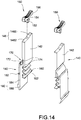
- the locking and release member 140 is preferably made of plastic and includes two arms 142 disposed in the two elongated grooves 134, a resilient element 160 disposed at one end of each of the arms 142, a connection element 170 connected to each of the arms 142, a fastening element 180 connected to each of the connection elements 170, and a pivot 182 protruding from one side of each of the fastening elements 180.
- the pivot 182 is pivotally connected to the pivot hole 136, and the fastening element 180 is rotatable about the pivot 182.
- each of the arms 142 is preferably disposed parallel to each of the fastening elements 180.
- the connection element 170 is connected to the arm 142 and the fastening element 180.
- the connection element 170 is preferably disposed between the arm 142 and the fastening element 180.
- Each of the connection elements 170 includes a body 172 and includes two connection ends 174 connected to the arm 142 and the fastening element 180 respectively, and a thickness of the connection end 174 is less than a thickness of the body 172.
- connection element 170 made of plastic has a width which preferably corresponds to a width of the arm 142 and a width of the fastening element 180, so the connection element 170 has sufficient strength, and each of the connection ends 174 can be moved easily by movement of the arm 142 or the fastening element 180.
- Each of the fastening elements 180 includes a fastening plate 184 and a hook 186 at one end of the fastening plate 184, the two pivots 182 protrude from two sides of the fastening plate 184, and each of the hooks 186 is disposed corresponding to each of the breaches 132 for engagement with each of the fastening holes 20.
- Each of the lateral walls 130 includes a recess 138 adjacent to the pivot hole 136, and the recess 138 receives one end of the fastening element 180.
- the pivot 182 preferably protrudes from the middle of the fastening plate 184, and thereby the fastening element 180 can rotate about the pivot 182, the recess 138 receives one end of the fastening plate 184, and as a result, the hook 186 at the other end of the fastening element 180 can be released from the fastening hole 20 (i.e., away from the breach 132).
- Each resilient element 160 and the arm 142 are preferably made of plastic or suitable materials.
- Each resilient element 160 is preferably a flat spring or a plate spring juxtaposed with the corresponding fastening element 180 in the elongated groove 134.
- each resilient element 160 is preferably connected to a lower end of each arm 142 in an integral form.
- each resilient element 160 can be a compression spring or other suitable spring assembled between the arm 142 and the housing 110; the present invention is not limited in this regard.
- each resilient element 160 includes a positioning end 162
- the housing 110 includes a joining member 124 corresponding to the positioning end 162
- the positioning end 162 is engaged with the joining member 124.
- the resilient elements 160 can elastically restore the two arms 142 to their initial positions.
- the positioning end 124 of the flat spring is preferably an insertion plate
- the joining member 124 of the housing 110 is a positioning block or other suitable part for insertion and fixation of the insertion plate.
- the at least one control element 150 is connected to the two arms 142.
- each of the arms 142 drives each of the connection elements 170 to move one end of each of the fastening elements 180, and the other end of each of the fastening elements 180 is away from the breach 132.
- the housing device 100 is disengaged and released from the two fastening holes 20.
- the electrical insertion end 210 of the housing device 100 is removed from the insertion slot 30 of the casing 10.
- Each control element 150 includes a push portion 152 for pushing each arm 142, a pivot portion 154 pivotally connected to the housing 110, and a handle 156 connected to the pivot portion 154.
- Each of the arms 142 of the locking and release member 140 includes a contact end 146 corresponding to each of the push portions 152.
- the housing 110 has an aperture 116 disposed corresponding to the pivot portion 154, and the handle 156 protrudes out of the housing 110.
- the control element 150 further includes a connection bar 158 connected to each handle 156.
- the connection bar 158 By rotating the connection bar 158, the two handles 156 are rotated to drive the push portions 152 to push each arm 142 downward.
- the push portion 152 is preferably an arc portion, and the contact end 146 is a planar surface.
- the push portion 152 of each control element 150 rotatably pushes the contact end 146 of each arm 142, the arm 142 pushes down the connection element 170 to thereby move one end of the fastening element 180.
- one end of the fastening element 180 moves to the recess 138, and the hook 186 is away from the breach 132, so that the fastening element 180 is disengaged and released from the fastening hole 20.
- the resilient element 160 is compressed to store energy.
- connection bar 158 when the connection bar 158 is rotated from a locking position to a releasing position, the slot 115 of the housing 110 receives the handle 156, and the connection bar 158 is rotated to above the cover plate 120. At this point, the user can rapidly detach the housing device 100 from the casing 10 by pulling up the connection bar 158, in a convenient and time-saving manner.
- each control element 150 is positioned in the aperture 116 of the housing 110, the pivot 182 of the fastening element 180 is pivotally connected to the pivot hole 136, and the positioning end 162 of the resilient element 160 is fastened to the joining member 124. Therefore, by operating the connection bar 158 or each handle 156, the user can easily detach the housing device 100 from the casing 10 or assemble the housing device 100 to the casing 10.
- the housing device 100 can be assembled to casing 10. That is to say, when each control element 150 returns from the releasing position to the locking position, each resilient element 160 releases the stored energy to exert an elastic force to automatically push back each arm 142, and each connection element 170 pulls each fastening element 180.
- the hook 186 returns to the breach 132 to be engaged with the fastening hole 20 again, so the electrical insertion end 210 of the housing device 100 is again electrically coupled to an insertion slot 30 of the casing 10.
- Figs. 7 to 9 showing a partial exploded view of the second embodiment, and a perspective view and a partial cross-sectional view showing the control element and the locking and release member according to the second embodiment.
- the present embodiment is different from the first embodiment in that, the push portion 152 of each control element 150 is preferably a cam having an arc periphery, and the contact end 146 of each arm 142 is a planar surface.
- the aperture 116 is formed on the lateral wall 130 for insertion of the pivot portion 154, and the handle 156 perpendicularly connected to the pivot portion 154 protrudes out of the lateral wall 130 for easy operations of users.
- the push portion 152 in the cam form rotatably pushes the arm 142 having a planar surface to move downward.
- the hook 186 of the fastening element 180 is rotated to be released from the fastening hole 20 of the casing 10, so as to be detached from the casing 10. Details regarding other components and connection relationships of the present embodiment are described above in the first embodiment, so a description thereof is omitted herein for brevity.
- each control element 150 is preferably a cylindrical cam.
- the contact end 146 of each arm 142 includes a planar surface 1462 and a chamfer 148 connected to the planar surface 1462.
- the cylindrical cam is hollow.
- One end of the cylindrical cam has a curved periphery to successfully cross the chamfer 148 to push the planar surface 1462.
- the aperture 116 is formed on the cover plate 120 for engagement with the pivot portion 154.
- Each handle 156 is perpendicularly connected to the pivot portion 154 and protrudes out of the cover plate 120 for easy operations of the users.
- each handle 156 When the user rotates each handle 156, the push portion 152 is rotated to cross the chamfer 148 to push the planar surface 1462, so that each arm 142 moves downward with respect to the elongated groove 134.
- the push portion 152 in the form of the cylindrical cam rotatedly moves from a low position to a high position, one side of the fastening element 180 moves and the fastening element 180 is rotated to be released from the casing 10.
- the housing device 100 is assembled to the casing 10
- the stored energy of the resilient element 160 is released to exert the elastic force to push each arm 142 back to the initial position. If the elastic force is properly designed, the contact end 146 automatically pushes back the push portion 152 to restore the handle 156 to its original position/a locking state.
- each control element 150 preferably includes a curved surface or an arc portion
- each of the contact ends 146 includes a planar surface 1462 and a curvy surface 1466 connected to the planar surface 1462.
- each push portion 152 moves from the planar surface 1462 to the curvy surface 1466 to push the arm 142 downward, and thereby the housing device 100 is released from the casing 10.
- the resilient element 160 recoils and pushes each arm 142 to restore the hook 186 to its original position.
- the push portion 152 moves along the contact end 146, from the curvy surface 1466 to the planar surface 1462, so that the handle 156 is restored to its original position/the locking state.
- each of the control elements 150 is a button 153, and each of the contact ends 146 is integrally formed with each of the buttons 153.
- each of the control elements 150 is preferably integrally formed with each of the arms 142.
- the housing 110 further includes two resilient clasps 126 extending from two sides of each elongated groove 134 respectively.
- Each arm 142 includes two protrusions 144 corresponding to the two resilient clasps 126 for engaging and locking each button 153 in position.
- the present embodiment further includes two unlock buttons 190, and each unlock button 190 includes a plurality of foot portions 192, so as to release each button 153 from the locking position/state.
- each foot portion 192 is inclined inwardly and is disposed corresponding to each resilient clasp 126.
- Each foot portion 192 presses each resilient clasp 126 outwardly to release each resilient clasp 126 from each of the protrusions 144.
- each unlock button 190 further includes a through hole 194 for insertion of the control element 150 and includes a limitation portion 196 for engagement with the housing 110.
- Each limitation portion 196 is, for example, a flange for limiting movement of each unlock button 190 with respect to the housing 110, so that each unlock button 190 is movable between the cover plate 120 and each resilient clasp 126.
- each control element 150 directly presses each button 153 to push down each arm 142 (pressing the button 153 to move it from the locking position to the releasing position), each protrusion 144 is engaged with each resilient clasp 126.
- the resilient element 160 is compressed and the connection element 170 pushes the fastening element 180 to move, so that the hook 186 of the fastening element 180 is away from the breach 132 (i.e., released from the fastening hole 20) to be released from the casing 10.
- each unlock button 190 When the locking and release member 140 returns to the locking state (i.e. engaged with the casing 10), it is required to press each unlock button 190, so that each foot portion 192 moves down to push each resilient clasp 126 outwardly. At this point, each control element 150 and each arm 142 are automatically restored to their original positions by means of the action of the resilient element 160. Therefore, the button 153 returns to its original position, and the hook 186 of the housing device 100 is again engaged with the fastening hole 20 of the casing 10, i.e. in the locking state.
- each foot portion 192 and each resilient clasp 126 have an inclined surface (not labelled, shown in Fig. 20 ) corresponding to each other, so that each resilient clasp 126 can be pushed outwardly in a smooth and elastic manner.
- each unlock button 190 cannot be pressed down any further, thereby providing a limitation effect.
- the present invention utilizes the control elements 150 of different structures. By operating the connection bar 158, operating each handle 156 or pressing each unlock button 190, or etc., each arm 142 can be depressed, thereby enhancing flexibility in operations or satisfying the users' needs in operations.
- the control elements 150 are two handles 156 separately disposed, the housing device 100 has to be detached and released from the casing 10 with the user's both hands.
- the housing 110 further includes a plurality of support blocks 128 on each lateral wall 130, so that each support block 128 guides and limits each arm 142 to move stably with respect to the elongated groove 134.
- each resilient element 160 automatically pushes back each arm 142 and each fastening element 180.
- Each hook 186 returns to each breach 132 again. Since the hook 186 of each fastening element 180 has a chamfer (not labelled) at one side, the housing device 100 can be engaged with the two fastening holes 20 of the casing 10 in a convenient and time-saving manner.
Landscapes
- Engineering & Computer Science (AREA)
- Microelectronics & Electronic Packaging (AREA)
- Mounting Of Printed Circuit Boards And The Like (AREA)
Priority Applications (1)
| Application Number | Priority Date | Filing Date | Title |
|---|---|---|---|
| EP17152396.2A EP3352544B1 (fr) | 2017-01-20 | 2017-01-20 | Dispositif de boîtier présentant une structure de verrouillage et de libération de type à pression |
Applications Claiming Priority (1)
| Application Number | Priority Date | Filing Date | Title |
|---|---|---|---|
| EP17152396.2A EP3352544B1 (fr) | 2017-01-20 | 2017-01-20 | Dispositif de boîtier présentant une structure de verrouillage et de libération de type à pression |
Publications (2)
| Publication Number | Publication Date |
|---|---|
| EP3352544A1 true EP3352544A1 (fr) | 2018-07-25 |
| EP3352544B1 EP3352544B1 (fr) | 2020-12-30 |
Family
ID=57868090
Family Applications (1)
| Application Number | Title | Priority Date | Filing Date |
|---|---|---|---|
| EP17152396.2A Active EP3352544B1 (fr) | 2017-01-20 | 2017-01-20 | Dispositif de boîtier présentant une structure de verrouillage et de libération de type à pression |
Country Status (1)
| Country | Link |
|---|---|
| EP (1) | EP3352544B1 (fr) |
Citations (3)
| Publication number | Priority date | Publication date | Assignee | Title |
|---|---|---|---|---|
| GB2211241A (en) * | 1987-10-21 | 1989-06-28 | Clarion Co Ltd | Fastening for detachable carborne electronic apparatus |
| US5152496A (en) * | 1990-01-10 | 1992-10-06 | Clarion Co., Ltd. | Lock structure for vehicle mounted type electronic equipment |
| US5889649A (en) * | 1994-03-01 | 1999-03-30 | Canon Kabushiki Kaisha | Information processing apparatus and a card-shaped adapter for smaller and larger storage medium |
-
2017
- 2017-01-20 EP EP17152396.2A patent/EP3352544B1/fr active Active
Patent Citations (3)
| Publication number | Priority date | Publication date | Assignee | Title |
|---|---|---|---|---|
| GB2211241A (en) * | 1987-10-21 | 1989-06-28 | Clarion Co Ltd | Fastening for detachable carborne electronic apparatus |
| US5152496A (en) * | 1990-01-10 | 1992-10-06 | Clarion Co., Ltd. | Lock structure for vehicle mounted type electronic equipment |
| US5889649A (en) * | 1994-03-01 | 1999-03-30 | Canon Kabushiki Kaisha | Information processing apparatus and a card-shaped adapter for smaller and larger storage medium |
Also Published As
| Publication number | Publication date |
|---|---|
| EP3352544B1 (fr) | 2020-12-30 |
Similar Documents
| Publication | Publication Date | Title |
|---|---|---|
| US10342147B2 (en) | Housing device having press-type locking and release structure | |
| US9801296B1 (en) | Housing device having pull-type locking and release structure | |
| JP5918566B2 (ja) | キーボード装置、キーボード保持装置、及び情報入力装置 | |
| US6992886B2 (en) | System for latching and ejecting a modular component from an electronic device | |
| US9761384B2 (en) | Shift assembly structure of switch device | |
| CN206273004U (zh) | 具有下压锁定释放结构的壳体装置 | |
| CN116234221B (zh) | 壳体组件、承载件与包括其的电子装置 | |
| CN103999183B (zh) | 辅助接触块 | |
| CN108174538B (zh) | 具有下压锁定释放结构的壳体装置 | |
| EP3352544A1 (fr) | Dispositif de boîtier présentant une structure de verrouillage et de libération de type à pression | |
| EP3352545B1 (fr) | Assemblage avec une structure de verrouillage et de libération du type à tirette | |
| CN105981125B (zh) | 开关模块和墙壁开关 | |
| CN102301740A (zh) | 话筒装置 | |
| CN206365174U (zh) | 具有上提锁定释放结构的壳体装置 | |
| TWI540607B (zh) | 配線器具 | |
| CN108174537B (zh) | 具有上提锁定释放结构的壳体装置 | |
| KR102183345B1 (ko) | 멀티탭 | |
| TW201440104A (zh) | 具有快速接線端子之按壓開關 | |
| CN111208874B (zh) | 电子装置 | |
| JP6015283B2 (ja) | スイッチ及び電子機器 | |
| CN111770658B (zh) | 电气模组框架及电气装置 | |
| US20260122160A1 (en) | Mounting frame | |
| JP6080535B2 (ja) | 電子機器 | |
| WO2020024124A1 (fr) | Structure de support | |
| JP4764769B2 (ja) | 電気機器の連結構造 |
Legal Events
| Date | Code | Title | Description |
|---|---|---|---|
| PUAI | Public reference made under article 153(3) epc to a published international application that has entered the european phase |
Free format text: ORIGINAL CODE: 0009012 |
|
| STAA | Information on the status of an ep patent application or granted ep patent |
Free format text: STATUS: REQUEST FOR EXAMINATION WAS MADE |
|
| 17P | Request for examination filed |
Effective date: 20171024 |
|
| AK | Designated contracting states |
Kind code of ref document: A1 Designated state(s): AL AT BE BG CH CY CZ DE DK EE ES FI FR GB GR HR HU IE IS IT LI LT LU LV MC MK MT NL NO PL PT RO RS SE SI SK SM TR |
|
| AX | Request for extension of the european patent |
Extension state: BA ME |
|
| STAA | Information on the status of an ep patent application or granted ep patent |
Free format text: STATUS: EXAMINATION IS IN PROGRESS |
|
| 17Q | First examination report despatched |
Effective date: 20200107 |
|
| GRAP | Despatch of communication of intention to grant a patent |
Free format text: ORIGINAL CODE: EPIDOSNIGR1 |
|
| STAA | Information on the status of an ep patent application or granted ep patent |
Free format text: STATUS: GRANT OF PATENT IS INTENDED |
|
| RIC1 | Information provided on ipc code assigned before grant |
Ipc: H05K 5/02 20060101AFI20200715BHEP Ipc: H05K 7/14 20060101ALI20200715BHEP |
|
| INTG | Intention to grant announced |
Effective date: 20200805 |
|
| RIN1 | Information on inventor provided before grant (corrected) |
Inventor name: WU, SHANG-TSAI |
|
| GRAS | Grant fee paid |
Free format text: ORIGINAL CODE: EPIDOSNIGR3 |
|
| GRAA | (expected) grant |
Free format text: ORIGINAL CODE: 0009210 |
|
| STAA | Information on the status of an ep patent application or granted ep patent |
Free format text: STATUS: THE PATENT HAS BEEN GRANTED |
|
| AK | Designated contracting states |
Kind code of ref document: B1 Designated state(s): AL AT BE BG CH CY CZ DE DK EE ES FI FR GB GR HR HU IE IS IT LI LT LU LV MC MK MT NL NO PL PT RO RS SE SI SK SM TR |
|
| REG | Reference to a national code |
Ref country code: GB Ref legal event code: FG4D |
|
| REG | Reference to a national code |
Ref country code: AT Ref legal event code: REF Ref document number: 1351274 Country of ref document: AT Kind code of ref document: T Effective date: 20210115 |
|
| REG | Reference to a national code |
Ref country code: DE Ref legal event code: R096 Ref document number: 602017030288 Country of ref document: DE |
|
| REG | Reference to a national code |
Ref country code: IE Ref legal event code: FG4D |
|
| PG25 | Lapsed in a contracting state [announced via postgrant information from national office to epo] |
Ref country code: RS Free format text: LAPSE BECAUSE OF FAILURE TO SUBMIT A TRANSLATION OF THE DESCRIPTION OR TO PAY THE FEE WITHIN THE PRESCRIBED TIME-LIMIT Effective date: 20201230 Ref country code: NO Free format text: LAPSE BECAUSE OF FAILURE TO SUBMIT A TRANSLATION OF THE DESCRIPTION OR TO PAY THE FEE WITHIN THE PRESCRIBED TIME-LIMIT Effective date: 20210330 Ref country code: GR Free format text: LAPSE BECAUSE OF FAILURE TO SUBMIT A TRANSLATION OF THE DESCRIPTION OR TO PAY THE FEE WITHIN THE PRESCRIBED TIME-LIMIT Effective date: 20210331 Ref country code: FI Free format text: LAPSE BECAUSE OF FAILURE TO SUBMIT A TRANSLATION OF THE DESCRIPTION OR TO PAY THE FEE WITHIN THE PRESCRIBED TIME-LIMIT Effective date: 20201230 |
|
| REG | Reference to a national code |
Ref country code: AT Ref legal event code: MK05 Ref document number: 1351274 Country of ref document: AT Kind code of ref document: T Effective date: 20201230 |
|
| PG25 | Lapsed in a contracting state [announced via postgrant information from national office to epo] |
Ref country code: BG Free format text: LAPSE BECAUSE OF FAILURE TO SUBMIT A TRANSLATION OF THE DESCRIPTION OR TO PAY THE FEE WITHIN THE PRESCRIBED TIME-LIMIT Effective date: 20210330 Ref country code: LV Free format text: LAPSE BECAUSE OF FAILURE TO SUBMIT A TRANSLATION OF THE DESCRIPTION OR TO PAY THE FEE WITHIN THE PRESCRIBED TIME-LIMIT Effective date: 20201230 Ref country code: SE Free format text: LAPSE BECAUSE OF FAILURE TO SUBMIT A TRANSLATION OF THE DESCRIPTION OR TO PAY THE FEE WITHIN THE PRESCRIBED TIME-LIMIT Effective date: 20201230 |
|
| REG | Reference to a national code |
Ref country code: NL Ref legal event code: MP Effective date: 20201230 |
|
| PG25 | Lapsed in a contracting state [announced via postgrant information from national office to epo] |
Ref country code: HR Free format text: LAPSE BECAUSE OF FAILURE TO SUBMIT A TRANSLATION OF THE DESCRIPTION OR TO PAY THE FEE WITHIN THE PRESCRIBED TIME-LIMIT Effective date: 20201230 |
|
| REG | Reference to a national code |
Ref country code: LT Ref legal event code: MG9D |
|
| PG25 | Lapsed in a contracting state [announced via postgrant information from national office to epo] |
Ref country code: SK Free format text: LAPSE BECAUSE OF FAILURE TO SUBMIT A TRANSLATION OF THE DESCRIPTION OR TO PAY THE FEE WITHIN THE PRESCRIBED TIME-LIMIT Effective date: 20201230 Ref country code: PT Free format text: LAPSE BECAUSE OF FAILURE TO SUBMIT A TRANSLATION OF THE DESCRIPTION OR TO PAY THE FEE WITHIN THE PRESCRIBED TIME-LIMIT Effective date: 20210430 Ref country code: RO Free format text: LAPSE BECAUSE OF FAILURE TO SUBMIT A TRANSLATION OF THE DESCRIPTION OR TO PAY THE FEE WITHIN THE PRESCRIBED TIME-LIMIT Effective date: 20201230 Ref country code: EE Free format text: LAPSE BECAUSE OF FAILURE TO SUBMIT A TRANSLATION OF THE DESCRIPTION OR TO PAY THE FEE WITHIN THE PRESCRIBED TIME-LIMIT Effective date: 20201230 Ref country code: CZ Free format text: LAPSE BECAUSE OF FAILURE TO SUBMIT A TRANSLATION OF THE DESCRIPTION OR TO PAY THE FEE WITHIN THE PRESCRIBED TIME-LIMIT Effective date: 20201230 Ref country code: LT Free format text: LAPSE BECAUSE OF FAILURE TO SUBMIT A TRANSLATION OF THE DESCRIPTION OR TO PAY THE FEE WITHIN THE PRESCRIBED TIME-LIMIT Effective date: 20201230 |
|
| PG25 | Lapsed in a contracting state [announced via postgrant information from national office to epo] |
Ref country code: AT Free format text: LAPSE BECAUSE OF FAILURE TO SUBMIT A TRANSLATION OF THE DESCRIPTION OR TO PAY THE FEE WITHIN THE PRESCRIBED TIME-LIMIT Effective date: 20201230 Ref country code: PL Free format text: LAPSE BECAUSE OF FAILURE TO SUBMIT A TRANSLATION OF THE DESCRIPTION OR TO PAY THE FEE WITHIN THE PRESCRIBED TIME-LIMIT Effective date: 20201230 |
|
| REG | Reference to a national code |
Ref country code: CH Ref legal event code: PL |
|
| PG25 | Lapsed in a contracting state [announced via postgrant information from national office to epo] |
Ref country code: LU Free format text: LAPSE BECAUSE OF NON-PAYMENT OF DUE FEES Effective date: 20210120 Ref country code: IS Free format text: LAPSE BECAUSE OF FAILURE TO SUBMIT A TRANSLATION OF THE DESCRIPTION OR TO PAY THE FEE WITHIN THE PRESCRIBED TIME-LIMIT Effective date: 20210430 |
|
| REG | Reference to a national code |
Ref country code: DE Ref legal event code: R097 Ref document number: 602017030288 Country of ref document: DE |
|
| REG | Reference to a national code |
Ref country code: BE Ref legal event code: MM Effective date: 20210131 |
|
| PG25 | Lapsed in a contracting state [announced via postgrant information from national office to epo] |
Ref country code: MC Free format text: LAPSE BECAUSE OF FAILURE TO SUBMIT A TRANSLATION OF THE DESCRIPTION OR TO PAY THE FEE WITHIN THE PRESCRIBED TIME-LIMIT Effective date: 20201230 Ref country code: IT Free format text: LAPSE BECAUSE OF FAILURE TO SUBMIT A TRANSLATION OF THE DESCRIPTION OR TO PAY THE FEE WITHIN THE PRESCRIBED TIME-LIMIT Effective date: 20201230 Ref country code: AL Free format text: LAPSE BECAUSE OF FAILURE TO SUBMIT A TRANSLATION OF THE DESCRIPTION OR TO PAY THE FEE WITHIN THE PRESCRIBED TIME-LIMIT Effective date: 20201230 |
|
| PLBE | No opposition filed within time limit |
Free format text: ORIGINAL CODE: 0009261 |
|
| STAA | Information on the status of an ep patent application or granted ep patent |
Free format text: STATUS: NO OPPOSITION FILED WITHIN TIME LIMIT |
|
| GBPC | Gb: european patent ceased through non-payment of renewal fee |
Effective date: 20210330 |
|
| PG25 | Lapsed in a contracting state [announced via postgrant information from national office to epo] |
Ref country code: DK Free format text: LAPSE BECAUSE OF FAILURE TO SUBMIT A TRANSLATION OF THE DESCRIPTION OR TO PAY THE FEE WITHIN THE PRESCRIBED TIME-LIMIT Effective date: 20201230 Ref country code: CH Free format text: LAPSE BECAUSE OF NON-PAYMENT OF DUE FEES Effective date: 20210131 Ref country code: LI Free format text: LAPSE BECAUSE OF NON-PAYMENT OF DUE FEES Effective date: 20210131 |
|
| 26N | No opposition filed |
Effective date: 20211001 |
|
| PG25 | Lapsed in a contracting state [announced via postgrant information from national office to epo] |
Ref country code: ES Free format text: LAPSE BECAUSE OF FAILURE TO SUBMIT A TRANSLATION OF THE DESCRIPTION OR TO PAY THE FEE WITHIN THE PRESCRIBED TIME-LIMIT Effective date: 20201230 Ref country code: GB Free format text: LAPSE BECAUSE OF NON-PAYMENT OF DUE FEES Effective date: 20210330 Ref country code: FR Free format text: LAPSE BECAUSE OF NON-PAYMENT OF DUE FEES Effective date: 20210228 Ref country code: IE Free format text: LAPSE BECAUSE OF NON-PAYMENT OF DUE FEES Effective date: 20210120 |
|
| PG25 | Lapsed in a contracting state [announced via postgrant information from national office to epo] |
Ref country code: SI Free format text: LAPSE BECAUSE OF FAILURE TO SUBMIT A TRANSLATION OF THE DESCRIPTION OR TO PAY THE FEE WITHIN THE PRESCRIBED TIME-LIMIT Effective date: 20201230 |
|
| PG25 | Lapsed in a contracting state [announced via postgrant information from national office to epo] |
Ref country code: IS Free format text: LAPSE BECAUSE OF FAILURE TO SUBMIT A TRANSLATION OF THE DESCRIPTION OR TO PAY THE FEE WITHIN THE PRESCRIBED TIME-LIMIT Effective date: 20210430 |
|
| PG25 | Lapsed in a contracting state [announced via postgrant information from national office to epo] |
Ref country code: BE Free format text: LAPSE BECAUSE OF NON-PAYMENT OF DUE FEES Effective date: 20210131 |
|
| PG25 | Lapsed in a contracting state [announced via postgrant information from national office to epo] |
Ref country code: NL Free format text: LAPSE BECAUSE OF NON-PAYMENT OF DUE FEES Effective date: 20201230 Ref country code: CY Free format text: LAPSE BECAUSE OF FAILURE TO SUBMIT A TRANSLATION OF THE DESCRIPTION OR TO PAY THE FEE WITHIN THE PRESCRIBED TIME-LIMIT Effective date: 20201230 |
|
| PG25 | Lapsed in a contracting state [announced via postgrant information from national office to epo] |
Ref country code: SM Free format text: LAPSE BECAUSE OF FAILURE TO SUBMIT A TRANSLATION OF THE DESCRIPTION OR TO PAY THE FEE WITHIN THE PRESCRIBED TIME-LIMIT Effective date: 20201230 Ref country code: HU Free format text: LAPSE BECAUSE OF FAILURE TO SUBMIT A TRANSLATION OF THE DESCRIPTION OR TO PAY THE FEE WITHIN THE PRESCRIBED TIME-LIMIT; INVALID AB INITIO Effective date: 20170120 |
|
| PG25 | Lapsed in a contracting state [announced via postgrant information from national office to epo] |
Ref country code: MK Free format text: LAPSE BECAUSE OF FAILURE TO SUBMIT A TRANSLATION OF THE DESCRIPTION OR TO PAY THE FEE WITHIN THE PRESCRIBED TIME-LIMIT Effective date: 20201230 |
|
| PG25 | Lapsed in a contracting state [announced via postgrant information from national office to epo] |
Ref country code: MT Free format text: LAPSE BECAUSE OF FAILURE TO SUBMIT A TRANSLATION OF THE DESCRIPTION OR TO PAY THE FEE WITHIN THE PRESCRIBED TIME-LIMIT Effective date: 20201230 |
|
| PGFP | Annual fee paid to national office [announced via postgrant information from national office to epo] |
Ref country code: DE Payment date: 20260130 Year of fee payment: 10 |
|
| PGFP | Annual fee paid to national office [announced via postgrant information from national office to epo] |
Ref country code: TR Payment date: 20260102 Year of fee payment: 10 |