EP3352609B1 - Schuh, insbesondere sportschuh - Google Patents
Schuh, insbesondere sportschuh Download PDFInfo
- Publication number
- EP3352609B1 EP3352609B1 EP15767090.2A EP15767090A EP3352609B1 EP 3352609 B1 EP3352609 B1 EP 3352609B1 EP 15767090 A EP15767090 A EP 15767090A EP 3352609 B1 EP3352609 B1 EP 3352609B1
- Authority
- EP
- European Patent Office
- Prior art keywords
- sole
- shoe
- hollow
- plug
- shoe according
- Prior art date
- Legal status (The legal status is an assumption and is not a legal conclusion. Google has not performed a legal analysis and makes no representation as to the accuracy of the status listed.)
- Active
Links
Images

Classifications
-
- A—HUMAN NECESSITIES
- A43—FOOTWEAR
- A43B—CHARACTERISTIC FEATURES OF FOOTWEAR; PARTS OF FOOTWEAR
- A43B13/00—Soles; Sole-and-heel integral units
- A43B13/02—Soles; Sole-and-heel integral units characterised by the material
- A43B13/023—Soles with several layers of the same material
-
- A—HUMAN NECESSITIES
- A43—FOOTWEAR
- A43B—CHARACTERISTIC FEATURES OF FOOTWEAR; PARTS OF FOOTWEAR
- A43B13/00—Soles; Sole-and-heel integral units
- A43B13/02—Soles; Sole-and-heel integral units characterised by the material
- A43B13/04—Plastics, rubber or vulcanised fibre
-
- A—HUMAN NECESSITIES
- A43—FOOTWEAR
- A43B—CHARACTERISTIC FEATURES OF FOOTWEAR; PARTS OF FOOTWEAR
- A43B13/00—Soles; Sole-and-heel integral units
- A43B13/02—Soles; Sole-and-heel integral units characterised by the material
- A43B13/12—Soles with several layers of different materials
- A43B13/125—Soles with several layers of different materials characterised by the midsole or middle layer
- A43B13/127—Soles with several layers of different materials characterised by the midsole or middle layer the midsole being multilayer
-
- A—HUMAN NECESSITIES
- A43—FOOTWEAR
- A43B—CHARACTERISTIC FEATURES OF FOOTWEAR; PARTS OF FOOTWEAR
- A43B13/00—Soles; Sole-and-heel integral units
- A43B13/14—Soles; Sole-and-heel integral units characterised by the constructive form
- A43B13/18—Resilient soles
- A43B13/181—Resiliency achieved by the structure of the sole
-
- A—HUMAN NECESSITIES
- A43—FOOTWEAR
- A43B—CHARACTERISTIC FEATURES OF FOOTWEAR; PARTS OF FOOTWEAR
- A43B3/00—Footwear characterised by the shape or the use
- A43B3/0036—Footwear characterised by the shape or the use characterised by a special shape or design
- A43B3/0047—Footwear characterised by the shape or the use characterised by a special shape or design parts having a male and corresponding female profile to fit together, e.g. form-fit
Definitions
- the invention relates to a shoe, in particular a sports shoe, which has a sole, which is connected to a shoe upper, according to the preamble of claim 1.
- the shoe should further have as constant as possible and unchangeable properties over time during its use.
- the invention has the object of providing a shoe of the type mentioned in such a way that it can be adapted to individual requirements in a simple and thus cost-effective manner. Furthermore, the disposal of the shoe should be possible in a simple manner.
- the first plug and the inner diameter of the hollow cylindrical portion of the first damping element are preferably tolerated to each other so that in the assembled state of the first plug and the hollow cylindrical section are arranged with press fit to each other; Accordingly, the second plug and the inner diameter of the hollow cylindrical portion of the second damping element are preferably tolerated to each other so that in the assembled state of the second plug and the hollow cylindrical portion are arranged with a press fit to each other.
- the first sole portion may be surrounded by a laterally upwardly extending edge. This gives the first sole part a cup-shaped structure.
- the second sole portion may have such an extent as to cover the rear sole area and leave the front sole area exposed.
- the connecting part can have plug connections only in the region which is covered by the second sole part. Furthermore, it can be provided in this case that the connecting part has in the region which is not covered by the second sole part, at least one newly formed footrest.
- the first damping elements are preferably made of two partial hollow bodies, which are connected to one another via a substantially perpendicular to the loading direction extending connecting portion, wherein a partial hollow body is formed by the hollow cylindrical portion in the upper region of the damping element.
- a partial hollow body is formed by the hollow cylindrical portion in the upper region of the damping element.
- the outer dimensions of the upper part-hollow body are smaller than the outer dimensions of the lower part-hollow body.
- the second damping elements may consist of two partial hollow bodies, which are connected to each other via a substantially perpendicular to the loading direction extending connecting portion, wherein a partial hollow body is formed by the hollow cylindrical portion in the lower region of the damping element. It can be provided that the outer dimensions of the lower part-hollow body are smaller than the outer dimensions of the upper part-hollow body.
- the connectors of the connecting part are preferably connected to one another with a number of rod-shaped or web-shaped connecting struts.
- two adjacent plug-in connections of the connecting part are each connected to each other with a connecting strut.
- the first sole part including all damping elements, the second sole part including all damping elements and the connecting part with all connectors are preferably each formed as one-piece moldings.
- the material is mostly plastic.
- the shoe upper is preferably connected to the first sole part. This results in improved kinematics when compressing the shoe due to the weight of the wearer of the shoe.
- the shoe upper may be connected in accordance with a preferred embodiment of the invention with the sole via a positive connection.
- the shaft, ie the shoe upper, of the shoe and its sole are sewn together.
- An essential design feature of the proposed solution is, however, the structure of the sole and especially their damping layer, which consists, at least in the heel area, ie in the rear sole area, of two specific layers of damping elements, as shown in the WO 03/092423 A1 are described and to which reference is expressly made.
- two superimposed layers of said damping elements are connected to each other by a connecting part with a grid-like structure via a plug connection.
- the cohesion of the individual components of the sole is preferably carried out exclusively by friction; An adhesive is preferably not used for this purpose.
- the lower damping element is designed in the manner of a cage, d. H. it preferably has a cup-shaped configuration.
- the upper damping element is preferably wedge-shaped and lies on the lower damping element. Both damping elements, so the upper and the lower layer are connected to each other via the connecting part with a lattice-shaped structure with a number of opposing, axially aligned pin (first and second connector).
- the connecting part ie the grid layer, extends mostly over the entire area of the midsole, wherein the upwards (towards the foot of the wearer) directed pins are present only in the area of the heel wedge in the rear (and middle) sole area.
- the connecting part closes off the piston-cylinder-shaped structure of the second damping elements towards the bottom, which is preferably carried out by, for example, a plate-shaped widening of the lattice base over each of the lower first damping elements.
- the support surface is increased for the foot or for a supplementary insole provided and thus improves the pressure distribution.
- the damping properties of the sole structure can be adjusted for example via different materials or hardnesses of the individual components. Preference is given to a plastic having a hardness range between 60 and 95 Shore A.
- the advantage of the proposed sole structure is first that the upper, second sole part is interchangeable, which results in the possibility to make said part individually customizable.
- a plugged connection between the shaft (shoe upper) and sole is provided, ie the sole is neither glued to the shaft nor sewn and can be separated at any time from the shaft.
- the basis for this is the principle of the first mentioned above and second sole part, which are connected by the connecting part via a plug connection.
- the first sole part with the first damping elements preferably consists of the running surface and a fully or partially over the sole extending integrated layer of said first damping elements.
- the shank (that is to say the upper part of the shoe) preferably has recesses (holes) in the insole area, which correspond in terms of their distribution and position to the plugs (pins) of the connector of the connecting part.
- the connecting part is inserted and positioned from above into the shaft so that the plugs (pins) coincide with the recesses. From below (below the shaft), the corresponding position of the damping elements is connected by the recesses with the plugs, d. H. pressed.
- the shaft is then clamped between the connecting part and the first sole part.
- the second sole part is then inserted from above into the shaft and attached to the connecting part.
- the connecting part can also be provided as a replacement for a strobe sole.
- This embodiment is similar to that explained above, with the difference that the shaft has no Stohlselohle with recesses (holes), but the Strobelsohle is replaced by the connecting part (grid).
- the connecting part with the corresponding plugs in this case has an additional base (preferably made of a softer plastic material having a hardness in the range between 65 and 90 Shore A, made of leather, synthetic leather or textile material), which the fills open grid interstices and forms the sub-step for sewing the shaft.
- This "grid Strobelsohle” is sewn to the - open at the bottom - shaft.
- the first and the second damping element are attached from below or from the inside.
- an outsole can be arranged on the underside of the first damping element and especially on the underside of its bottom plate.
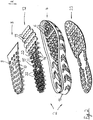
- FIG. 1 a shoe 1 in the form of a sports shoe is indicated, which has a shoe upper 3 and a sole 2.
- the shoe 1 is when used properly on the floor and is loaded by the foot of the wearer. This results in a loading direction R, which corresponds to the vertical direction.
- a back sole region 17 and a front sole region 18 are marked, each extending over approximately one third of the total length of the shoe 1; in between there is a middle sole area, which is not specified.
- the sole has a first, lower sole part 4 and a second, upper sole part 8. Both sole parts 4, 8 are connected to each other via a connecting part 12, in the manner of a connector and without the use of an adhesive.
- the first sole part 4 has a circumferentially circumferential edge 16, so that this part is formed like a shell.
- first sole part 4 On the underside of the first sole part 4, an outsole 23 is arranged. Both the first sole part 4 and the second sole part 8 comprise respective first damping elements 6 and second damping elements 10.
- the first damping elements 6 of the first sole part 4 extend upwards from a bottom plate 5 of the first sole part 4, while the second damping elements 10 of FIG second sole part 8 extending from a cover plate 9 down.
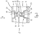
- Both the first damping elements 6 and the second damping elements 10 are formed in the manner of a piston-cylinder damping system.
- a hollow portion of the damping element with smaller outer dimensions enters a hollow body-shaped area with larger outer dimensions (“cylinder”) and thus develops a damping effect.
- first damping element 6 and the second damping element 10 are formed in the manner of a piston-cylinder unit, wherein a connecting portion 20 and 21, the connection between the "piston" and the "cylinder" produces.
- the first damping element 6 has a hollow cylindrical section 7 in its upper region
- the second damping element 10 has a hollow cylindrical section 11 in its lower region.
- the lower first damping element 6 is connected to the upper second damping element 10 via a plug connection, which is accomplished via the connecting part 12.
- the connecting part 12 has a number of plug connections 13 which have first plug 14 and second plug 15 aligned in the loading direction R.
- the second sole element 8 in this case has an extension which essentially covers only the rear sole region 17 and possibly also the middle sole region; however, the front sole region remains free of the second sole element.
- FIG. 2 shows that the second sole element 8 is so far wedge-shaped and the underlying connection part 12 is not completely covered.
- the connecting part 12 has in its area in the front sole region 18 is arranged, a common, plate-shaped footrest 19th
- the connecting part 12 consists of individual connectors 13 with respective lower first connectors 14 and upper second connectors 15, wherein the individual connectors 13 are connected to each other via connecting struts 22. Therefore, for the connection part 12, a lattice-shaped structure that can be assembled as a whole results.
- the proposed concept is based on the fact that two layers of piston-cylinder-like damping elements one above the other, d. H. are arranged in series, wherein the connection of these superimposed damping elements is accomplished via the connecting part 12.
- connection of the shoe upper 3 with the sole 2 can take place in different ways:
- the shoe upper 3 can be made as a closed (sock-like) structure running around the sole of the wearer, for example, the lower end being realized by a buff sole which is sewn to the shoe upper.
- Strobelsohle can openings (Punchings) may be introduced, which correspond to the arrangement of the plug (ie the hole pattern) of the connecting part 12.
- the shoe upper prepared in this way is then placed between the individual sole parts such that the push-button sole and thus also the shoe upper 3 are connected in a form-fitting manner to the sole 2.
- a textile material section is inserted into the injection mold, wherein said material section forms the storm sole or a part of the shoe upper 3.
- the sole part can in particular be the connecting part 12 or the second sole part 8 be.
- the textile material is previously provided with a corresponding perforation corresponding to the hole pattern of the pin and so inserted into the injection mold.
- said textile material section which forms the strobe sole, virtually acts as a carrier material, which is inserted into the injection mold and then only the grid structure applied by the injection molding process, which is used for producing the described Plug connection is needed.
- the second sole member 8 is considered.
- the second sole part 8 is provided with the textile material section according to the described type, the use of an insole can advantageously be dispensed with in the given case, since this function is then perceived by the strobel sole thus produced.
- the part thus produced is thus used as a strobe sole and has the connectors for the sole described.
- Schnürbandagen are part of the inserted into the injection molding textile material section.
- the variants described above are used in combination in that they are used in each case only in a specific region of the sole (that is, for example, in the forefoot, midfoot or hindfoot region).
- the grid required for the connector can be molded directly to the Strobelsohle only in the forefoot area, while in the joint (ie midfoot) area and heel area this is not the case; here would be the connection of the shoe upper with the sole then as a pure plug connection done (by means of the mentioned hole pattern in the Strobelsohle).
- edge portions of the type of edge 16 are provided (only) in the region of the sole tip and in the region of the heel of the sole become.
- the individual parts of the sole are made of polyolefin elastomers (eg TPE-S, TPU or PA).
- polyolefin elastomers eg TPE-S, TPU or PA.
- a knitted material can also be provided.
Landscapes
- Chemical & Material Sciences (AREA)
- Engineering & Computer Science (AREA)
- Materials Engineering (AREA)
- Footwear And Its Accessory, Manufacturing Method And Apparatuses (AREA)
Description
- Die Erfindung betrifft einen Schuh, insbesondere einen Sportschuh, der eine Sohle aufweist, die mit einem Schuhoberteil verbunden ist, gemäß dem Oberbegriff des Anspruchs 1.
- Gattungsgemäße Schuhe sind hinlänglich im Stand der Technik bekannt. Dabei besteht eine Forderung, den Sportschuh - insbesondere, wenn er als Sportschuh verwendet wird - möglichst gut an individuelle Bedürfnisse anpassen zu können; dies gilt insbesondere mit Blick auf das Feder- und Dämpfverhalten des Schuhs. Siehe z.B.
DE 20 2005 012 062 U1 . - Der Schuh soll des weiteren während seines Gebrauchs möglichst konstante und über die Zeit unveränderliche Eigenschaften aufweisen.
- Ein weiterer Aspekt, dem zunehmend Bedeutung zukommt, ist derjenige des Recyclings. Hier ist es wünschenswert, einen gattungsgemäßen Schuh so aufzubauen, dass er sortenrein wieder entsorgt werden kann.
- Der Erfindung liegt die Aufgabe zugrunde, einen Schuh der eingangs genannten Art so fortzubilden, dass er in einfacher und somit kostengünstiger Weise an individuelle Anforderungen angepasst werden kann. Weiterhin soll die Entsorgung des Schuhs in einfacher Weise möglich sein.
- Die Lösung dieser Aufgabe durch die Erfindung ist durch die kennzeichnenden Merkmale des Anspruchs 1 definiert.
- Der erste Stecker und der Innendurchmesser des hohlzylindrischen Abschnitts des ersten Dämpfungselements sind vorzugsweise so zueinander toleriert, dass im zusammengesteckten Zustand der erste Stecker und der hohlzylindrische Abschnitt mit Presspassung zueinander angeordnet sind; entsprechend sind der zweite Stecker und der Innendurchmesser des hohlzylindrischen Abschnitts des zweiten Dämpfungselements vorzugsweise so zueinander toleriert, dass im zusammengesteckten Zustand der zweite Stecker und der hohlzylindrische Abschnitt mit Presspassung zueinander angeordnet sind.
- Das erste Sohlenteil kann von einem seitlich sich nach oben erstreckenden Rand umgeben sein. Hierdurch erhält das erste Sohlenteil eine schalenförmige Struktur.
- Das zweite Sohlenteil kann eine solche Ausdehnung haben, dass es den hinteren Sohlenbereich abdeckt und den vorderen Sohlenbereich frei lässt. Das Verbindungsteil kann dabei nur in dem Bereich Steckverbindungen aufweisen, der durch das zweite Sohlenteil abgedeckt ist. Ferner kann hierbei vorgesehen sein, dass das Verbindungsteil in dem Bereich, der nicht durch das zweite Sohlenteil abgedeckt ist, mindestens eine eben ausgebildete Fußauflage aufweist.
- Die ersten Dämpfungselemente bestehen bevorzugt aus zwei Teil-Hohlkörpern, die über einen im wesentlichen sich senkrecht zur Belastungsrichtung erstreckenden Verbindungsabschnitt miteinander verbunden sind, wobei der eine Teil-Hohlkörper durch den hohlzylindrischen Abschnitt im oberen Bereich des Dämpfungselements gebildet wird. In diesem Falle ist bevorzugt vorgesehen, dass die Außenabmessungen des oberen Teil-Hohlkörpers kleiner sind als die Außenabmessungen des unteren Teil-Hohlkörpers.
- Analog können die zweiten Dämpfungselemente aus zwei Teil-Hohlkörpern bestehen, die über einen im wesentlichen sich senkrecht zur Belastungsrichtung erstreckenden Verbindungsabschnitt miteinander verbunden sind, wobei der eine Teil-Hohlkörper durch den hohlzylindrischen Abschnitt im unteren Bereich des Dämpfungselements gebildet wird. Hierbei kann vorgesehen sein, dass die Außenabmessungen des unteren Teil-Hohlkörpers kleiner sind als die Außenabmessungen des oberen Teil-Hohlkörpers.
- Die Steckverbindungen des Verbindungsteils sind vorzugsweise mit einer Anzahl stab- oder stegförmiger Verbindungsstreben miteinander verbunden. Insbesondere sind hierbei zwei benachbarte Steckverbindungen des Verbindungsteils mit je einer Verbindungsstrebe miteinander verbunden.
- Das erste Sohlenteil samt allen Dämpfungselementen, das zweite Sohlenteil samt allen Dämpfungselementen und das Verbindungsteil mit allen Steckverbindungen sind dabei vorzugsweise jeweils als einstückige Formteile ausgebildet. Der Werkstoff ist zumeist Kunststoff.
- Das Schuhoberteil ist dabei bevorzugt mit dem ersten Sohlenteil verbunden. Dies ergibt eine verbesserte Kinematik beim Einfedern des Schuhs infolge der Gewichtskraft des Trägers des Schuhs.
- Das Schuhoberteil kann gemäß einer bevorzugten Ausgestaltung der Erfindung mit der Sohle über eine formschlüssige Verbindung verbunden sein.
- Gemäß einer anderen Ausführungsform der Erfindung werden der Schaft, d. h. das Schuhoberteil, des Schuhs und dessen Sohle miteinander vernäht.
- Wesentliches Gestaltungsmerkmal der vorgeschlagenen Lösung ist indes der Aufbau der Sohle und namentlich deren Dämpfungsschicht, die zumindest im Fersenbereich, d. h. im hinteren Sohlenbereich, aus zwei spezifischen Lagen von Dämpfungselementen besteht, wie sie in der
WO 03/092423 A1 - Das untere Dämpfungselement ist nach Art eines Käfigs ausgebildet, d. h. es hat bevorzugt eine schalenförmige Ausgestaltung. Das obere Dämpfungselement ist bevorzugt keilförmig ausgebildet und liegt auf dem unteren Dämpfungselement. Beide Dämpfungselemente, also die obere und die untere Lage, sind über das Verbindungsteil mit gitterförmiger Struktur mit einer Anzahl jeweils gegenüberliegenden, axial fluchtender Zapfen (erster und zweiter Stecker) miteinander verbunden.
- Das Verbindungsteil, d. h. die Gitterlage, erstreckt sich dabei zumeist über den gesamten Bereich der Zwischensohle, wobei die nach oben (zum Fuß des Trägers hin) gerichteten Zapfen nur im Bereich des Absatzkeiles im hinteren (und mittleren) Sohlenbereich vorhanden sind. Im vorderen Sohlenbereich (Vorfußbereich) schließt das Verbindungsteil die Kolben-Zylinder-förmige Struktur der zweiten Dämpfungselemente zum Boden hin ab, was bevorzugt durch eine beispielsweise tellerförmige Verbreiterung der Gitterbasis über jedem der unten liegenden ersten Dämpfungselemente erfolgt. Hierdurch wird die Auflagefläche für den Fuß bzw. für eine ergänzend vorgesehene Einlegesohle vergrößert und so die Druckverteilung verbessert.
- Die Dämpfungseigenschaften der Sohlenstruktur können beispielsweise über unterschiedliche Materialien bzw. Härten der einzelnen Komponenten eingestellt werden. Bevorzugt ist ein Kunststoff mit einem Härtebereich zwischen 60 und 95 Shore A.
- Der Vorteil der vorgeschlagenen Sohlenstruktur ist zunächst, dass das obere, zweite Sohlenteil auswechselbar ist, wodurch sich die Möglichkeit ergibt, besagtes Teil individuell anpassbar zu machen.
- Vorteilhaft ist weiterhin, dass die zum Einsatz kommenden Sohlenteile im Allgemeinen eine sehr gute Haltbarkeit aufweisen und somit eine geringe Tendenz zu einer dauerhaften Verformung haben.
- Weiterhin ist sehr vorteilhaft, dass kein Kleben von Komponenten notwendig ist.
- Schließlich ist es mit Blick auf das Recycling vorteilhaft, dass eine (zumindest teilweise) sortenreine Trennung der einzelnen Komponenten möglich ist.
- Möglich ist der Einsatz eines Schuhoberteils sowohl mit als auch ohne Strobelsohle.
- Bei einem Schuhoberteil mit Strobelsohle ist eine gesteckte Verbindung zwischen Schaft (Schuhoberteil) und Sohle vorgesehen, d. h. die Sohle ist weder an den Schaft angeklebt noch angenäht und kann jederzeit vom Schaft getrennt werden. Die Basis hierfür ist das oben erwähnte Prinzip des ersten und zweiten Sohlenteils, die durch das Verbindungsteil per Steckverbindung miteinander verbunden sind.
- Das erste Sohlenteil mit den ersten Dämpfungselementen besteht dabei bevorzugt aus der Lauffläche und einer sich ganz oder teilweise über die Sohle erstreckenden integrierten Lage der genannten ersten Dämpfungselemente.
- Der Schaft (d. h. das Schuhoberteil) weist hierbei bevorzugt im Brandsohlenbereich Ausnehmungen (Löcher) auf, die hinsichtlich ihrer Verteilung und Position den Steckern (Zapfen) der Steckverbindung des Verbindungsteils entsprechen. Das Verbindungsteil wird von oben in den Schaft so eingeführt und positioniert, dass die Stecker (Zapfen) mit den Ausnehmungen übereinstimmen. Von unten (unter dem Schaft) wird die entsprechende Lage der Dämpfungselemente durch die Ausnehmungen mit den Steckern verbunden, d. h. eingedrückt. Der Schaft wird dann zwischen dem Verbindungsteil und dem ersten Sohlenteil eingeklemmt. Das zweite Sohlenteil wird dann von oben in den Schaft eingeführt und auf das Verbindungsteil aufgesteckt.
- Das Verbindungsteil kann auch als Ersatz für eine Strobelsohle vorgesehen werden. Diese Ausführungsform ist ähnlich wie die oben erläuterte, wobei der Unterschied vorliegt, dass der Schaft keine Strobelsohle mit Ausnehmungen (Löchern) aufweist, sondern die Strobelsohle durch das Verbindungsteil (Gitter) ersetzt wird. Das Verbindungsteil mit den entsprechenden Steckern hat in diesem Fall eine zusätzliche Basis (vorzugsweise aus einem weicheren Kunststoff-Material mit einer Härte im Bereich zwischen 65 und 90 Shore A, aus Leder, aus synthetischem Leder oder aus Textilmaterial), welches die offenen Gitterzwischenräume ausfüllt und den Untertritt für das Annähen des Schaftes formt.
- Diese "Gitter-Strobelsohle" wird an den - unten offenen - Schaft angenäht. Das erste und das zweite Dämpfungselement werden von unten bzw. von innen aufgesteckt.
- Generell kann an der Unterseite des ersten Dämpfungselements und namentlich an der Unterseite dessen Bodenplatte eine Außensohle angeordnet werden.
- In der Zeichnung ist ein Ausführungsbeispiel der Erfindung dargestellt. Es zeigen:
- Fig. 1
- in der Seitenansicht einen Sportschuh,
- Fig. 2
- in Explosionsdarstellung die Sohle des Sportschuhs gemäß
Figur 1 und - Fig. 3
- einen Teil der Seitenansicht in geschnittener Darstellung.
- In
Figur 1 ist ein Schuh 1 in Form eines Sportschuhs angedeutet, der ein Schuhoberteil 3 und eine Sohle 2 aufweist. Der Schuh 1 steht bei bestimmungsgemäßer Verwendung auf dem Boden und wird durch den Fuß des Trägers belastet. Hierdurch ergibt sich eine Belastungsrichtung R, die der vertikalen Richtung entspricht. InFigur 1 ist ein hinterer Sohlenbereich 17 und ein vorderer Sohlenbereich 18 markiert, die sich jeweils etwa über ein Drittel der gesamten Länge des Schuhs 1 erstrecken; dazwischen liegt ein mittlerer Sohlenbereich, der nicht näher bezeichnet ist. - Aus den
Figuren 2 und3 geht der erfindungsgemäße Aufbau der Sohle 2 im Detail hervor:
Die Sohle weist ein erstes, unteres Sohlenteil 4 sowie ein zweites, oberes Sohlenteil 8 auf. Beide Sohlenteile 4, 8 sind über ein Verbindungsteil 12 miteinander verbunden, und zwar nach Art einer Steckverbindung und ohne Einsatz eines Klebstoffs. Wie inFigur 2 gesehen werden kann, hat das erste Sohlenteil 4 einen in Umfangsrichtung umlaufenden Rand 16, so dass dieses Teil schalenartig ausgebildet ist. - An der Unterseite des ersten Sohlenteils 4 ist eine Außensohle 23 angeordnet. Sowohl das erste Sohlenteil 4 als auch das zweite Sohlenteil 8 umfassen jeweilige erste Dämpfungselemente 6 bzw. zweite Dämpfungselemente 10. Die ersten Dämpfungselemente 6 des ersten Sohlenteils 4 erstrecken sich von einer Bodenplatte 5 des ersten Sohlenteils 4 aus nach oben, während die zweiten Dämpfungselemente 10 des zweiten Sohlenteils 8 sich von einer Deckplatte 9 aus nach unten erstrecken.
- Sowohl die ersten Dämpfungselemente 6 als auch die zweiten Dämpfungselemente 10 sind nach Art eines Kolben-Zylinder-Dämpfungssystems ausgebildet. Hiernach ist vorgesehen, dass ein hohler Abschnitt des Dämpfungselements mit kleineren Außendimensionen ("Kolben") in einen hohlkörperartig ausgebildeten Bereich mit größeren Außendimensionen ("Zylinder") eintritt und so eine Dämpfungswirkung entfaltet.
- Zur Ausgestaltung dieser Art von Dämpfungselementen sei auf die
WO 03/092423 A1 - Insoweit sei erwähnt, dass das erste Dämpfungselement 6 sowie das zweite Dämpfungselement 10 nach Art einer Kolben-Zylinder-Einheit ausgebildet sind, wobei ein Verbindungsabschnitt 20 bzw. 21 die Verbindung zwischen dem "Kolben" und dem "Zylinder" herstellt.
- Demgemäß weist das erste Dämpfungselement 6 in seinem oben liegenden Bereich einen hohlzylindrischen Abschnitt 7 auf, während das zweite Dämpfungselement 10 in seinem unten liegenden Bereich einen hohlzylindrischen Abschnitt 11 aufweist.
- Das untere erste Dämpfungselement 6 ist mit dem oberen zweiten Dämpfungselement 10 über eine Steckverbindung verbunden, was über das Verbindungsteil 12 bewerkstelligt wird. Das Verbindungsteil 12 weist hierzu eine Anzahl Steckverbindungen 13 auf, die in Belastungsrichtung R fluchtende erste Stecker 14 und zweite Stecker 15 aufweisen.
- Das zweite Sohlenelement 8 weist dabei eine Erstreckung auf, die im wesentlichen lediglich den hinteren Sohlenbereich 17 und gegebenenfalls auch noch den mittleren Sohlenbereich abdeckt; der vordere Sohlenbereich bleibt indes frei vom zweiten Sohlenelement.
- Aus
Figur 2 geht hervor, dass das zweite Sohlenelement 8 insoweit keilförmig ausgebildet ist und das unter sich liegende Verbindungsteil 12 nicht vollständig abdeckt. - Damit für die Auflage des Fußes dennoch eine gute Druckverteilung gewährleistet ist, hat daher das Verbindungsteil 12 in seinem Bereich, der im vorderen Sohlenbereich 18 angeordnet ist, eine verbreitete, tellerförmige Fußauflage 19.
- Das Verbindungsteil 12 besteht aus einzelnen Steckverbindungen 13 mit jeweiligen unteren ersten Steckern 14 und oberen zweiten Steckern 15, wobei die einzelnen Steckverbindungen 13 über Verbindungsstreben 22 miteinander verbunden sind. Daher ergibt sich für das Verbindungsteil 12 eine gitterförmige Struktur, die als Ganzes montiert werden kann.
- Somit stellt das vorgeschlagene Konzept darauf ab, dass zwei Lagen von Kolben-Zylinder-artigen Dämpfungselementen übereinander, d. h. in Reihe angeordnet sind, wobei die Verbindung dieser übereinander platzierten Dämpfungselemente über das Verbindungsteil 12 bewerkstelligt wird.
- Hierbei ist lediglich eine Verbindung per Reibschluss und ohne Klebstoff vorgesehen. Es erfolgt vielmehr ein Zusammenstecken des ersten und des zweiten Sohlenteils mittels des Verbindungsteils.
- Ist das Schuhoberteil direkt an dem ersten Sohlenteil angeordnet, hat dies den Vorteil, dass Einfederbewegungen des Schuhs eine verminderte Relativbewegung zwischen Schuhoberteil und Fuß zur Folge haben.
- Generell gilt, dass die Verbindung des Schuhoberteils 3 mit der Sohle 2 auf verschiedene Art und Weise erfolgen kann:
Das Schuhoberteil 3 kann als um die Fußsohle des Trägers herum verlaufende geschlossene (sockenartige) Struktur ausgeführt werden, wobei beispielsweise der untere Abschluss durch eine Strobelsohle realisiert wird, die mit dem Schuhoberteil vernäht wird. In der Strobelsohle können Öffnungen (Ausstanzungen) eingebracht sein, die der Anordnung der Stecker (d. h. dem Lochmuster) des Verbindungsteils 12 entsprechen. Bei der Montage der Sohle 2 wird dann das so vorbereitete Schuhoberteil zwischen den einzelnen Sohlenteilen platziert, dass die Strobelsohle und somit auch das Schuhoberteil 3 formschlüssig mit der Sohle 2 verbunden. - Vorgesehen kann auch werden, dass beim Spritzgießprozess eines der Sohlenteile ein textiler Materialabschnitt mit ins Spritzgießwerkzeug eingelegt wird, wobei besagter Materialabschnitt die Strobelsohle bzw. einen Teil des Schuhoberteils 3 ausbildet. Somit liegt dann eine feste und über den Spritzgießprozess hergestellte Verbindung zwischen einem der Sohlenteile und dem textilen Materialabschnitt vor und so eine Verbindung zwischen Sohle 2 und Schuhoberteil 3 nach der Montage der Sohle 2. Das genannte Sohlenteil kann dabei insbesondere das Verbindungsteil 12 oder das zweite Sohlenteil 8 sein.
- Beim Anspritzen des Sohlenteils in der genannten Art kann auch vorgesehen werden, dass das textile Material vorher mit einer entsprechenden Perforation entsprechend dem Lochmuster der Zapfen versehen und so ins Spritzgießwerkzeug eingelegt wird.
- Als Variation dieses Konzepts kann weitergehend vorgesehen werden, dass der genannte textile Materialabschnitt, der die Strobelsohle bildet, quasi als Trägermaterial fungiert, der in das Spritzgießwerkzeug eingelegt und auf den durch den Spritzgießprozess dann lediglich noch die Gitterstruktur aufgebracht wird, die für das Herstellen der beschriebenen Steckverbindung benötigt wird. Hierfür kommt insbesondere das zweite Sohlenteil 8 in Betracht.
- Wird nach der beschriebenen Art das zweite Sohlenteil 8 mit dem textilen Materialabschnitt versehen, kann vorteilhafter Weise im gegebenen Falle auf die Verwendung einer Einlegesohle verzichtet werden, da diese Funktion dann von der so hergestellten Strobelsohle wahrgenommen wird. Das so hergestellte Teil wird also als Strobelsohle verwendet und weist die Steckverbindungen für die beschriebene Sohle auf.
- Vorteilhafter Weise ergibt sich ein sehr flexibler und leichter Verbund, der einfach zu nähen ist.
- Bevorzugt kann dann auch auf einen umlaufenden Rand 16 am ersten Sohlenteil 4 verzichtet werden.
- Dabei kann auch vorgesehen werden, dass Schnürbandagen Teil des ins Spritzgießwerkzeug eingelegten textilen Materialabschnitts sind.
- Bei entsprechender Ausbildung kann vorteilhafter Weise erreicht werden, dass wiederum ein flexibler und leichter Aufbau entsteht, der einfach zu fertigen ist. Die Kunststoffgitterbasis der Sohle ist hier klar definiert, sauber ausgestaltet und gut abgedichtet. Weiterhin können in einfacher Weise Verstärkungen (zum Beispiel eine Fersenkappe) integriert werden.
- Vorgesehen kann auch werden, dass die oben beschriebenen Varianten insofern kombiniert eingesetzt werden, als dass sie jeweils nur in einem bestimmten Bereich der Sohle (also zum Beispiel im Vorderfuß-, Mittelfuß- oder Hinterfußbereich) verwendet werden. So kann beispielsweise das für die Steckverbindung benötigte Gitter nur im Vorderfuß-Bereich direkt an die Strobelsohle angespritzt werden, während im Gelenk- (d. h. Mittelfuß-) Bereich und Fersenbereich dies nicht der Fall ist; hier würde die Verbindung des Schuhoberteils mit der Sohle dann also als reine Steckverbindung erfolgen (mittels des erwähnten Lochmusters in der Strobelsohle).
- Der Vorteil dieser Variante ist, dass keine Plastikflächen im Schuh vorhanden sind und keine Dämpfungsbewegung im Schuh auftritt. Weiterhin ist der Zusammenbau des Schuhs bzw. der Sohle sehr einfach.
- Als weitere Variation des beschriebenen Konzepts kann vorgesehen werden, dass zwar weitgehend auf einen Rand 16 am bzw. im ersten Sohlenteil 4 verzichtet wird, dass allerdings Randabschnitte nach Art des Randes 16 (nur) im Bereich der Sohlenspitze und im Bereich der Ferse der Sohle vorgesehen werden.
- Bevorzugt sind die einzelnen Teile der Sohle aus Polyolefin-Elastomeren (z. B. TPE-S, TPU oder PA) hergestellt.
- Als Schuhoberteil kann auch ein gestricktes Material vorgesehen werden.
-
- 1
- Schuh
- 2
- Sohle
- 3
- Schuhoberteil
- 4
- erstes Sohlenteil
- 5
- Bodenplatte
- 6
- erstes Dämpfungselement
- 7
- hohlzylindrischer Abschnitt
- 8
- zweites Sohlenteil
- 9
- Deckplatte
- 10
- zweites Dämpfungselement
- 11
- hohlzylindrischer Abschnitt
- 12
- Verbindungsteil
- 13
- Steckverbindung
- 14
- erster Stecker
- 15
- zweiter Stecker
- 16
- Rand
- 17
- hinterer Sohlenbereich
- 18
- vorderer Sohlenbereich
- 19
- Fußauflage
- 20
- Verbindungsabschnitt
- 21
- Verbindungsabschnitt
- 22
- Verbindungsstrebe
- 23
- Außensohle
- R
- Belastungsrichtung
Claims (15)
- Schuh (1), insbesondere Sportschuh, der eine Sohle (2) aufweist, die mit einem Schuhoberteil (3) verbunden ist, wobei die Sohle (2) umfasst:- ein erstes Sohlenteil (4), das eine Bodenplatte (5) aufweist, wobei an der Bodenplatte (5) eine Anzahl sich in Belastungsrichtung (R) erstreckende erste Dämpfungselemente (6) angeformt sind, wobei die ersten Dämpfungselemente (6) als Hohlkörper ausgebildet sind und in ihrem oberen Endbereich einen hohlzylindrischen Abschnitt (7) aufweisen;- ein zweites Sohlenteil (8), das eine Deckplatte (9) aufweist, wobei an der Deckplatte (9) eine Anzahl sich in Belastungsrichtung (R) erstreckende zweite Dämpfungselemente (10) angeformt sind, wobei die zweiten Dämpfungselemente (10) als Hohlkörper ausgebildet sind und in ihrem unteren Endbereich einen hohlzylindrischen Abschnitt (11) aufweisen;dadurch gekennzeichnet, dass die Sohle (2) umfasst:- ein Verbindungsteil (12), das eine Anzahl miteinander verbundener Steckverbindungen (13) aufweist, wobei jede Steckverbindung (13) einen in Belastungsrichtung (R) nach unten gerichteten ersten Stecker (14) und einen in Belastungsrichtung (R) nach oben gerichteten zweiten Stecker (15) aufweist, wobei der erste Stecker (14) ausgebildet ist, um reibschlüssig in den hohlzylindrischen Abschnitt (7) des ersten Dämpfungselements (6) einzugreifen, und wobei der zweite Stecker (15) ausgebildet ist, um reibschlüssig in den hohlzylindrischen Abschnitt (11) des zweiten Dämpfungselements (10) einzugreifen.
- Schuh nach Anspruch 1, dadurch gekennzeichnet, dass der erste Stecker (14) und der Innendurchmesser des hohlzylindrischen Abschnitts (7) des ersten Dämpfungselements (6) so zueinander toleriert sind, dass im zusammengesteckten Zustand der erste Stecker (14) und der hohlzylindrische Abschnitt (7) mit Presspassung zueinander angeordnet sind, und dass der zweite Stecker (15) und der Innendurchmesser des hohlzylindrischen Abschnitts (11) des zweiten Dämpfungselements (10) so zueinander toleriert sind, dass im zusammengesteckten Zustand der zweite Stecker (15) und der hohlzylindrische Abschnitt (11) mit Presspassung zueinander angeordnet sind.
- Schuh nach Anspruch 1 oder 2, dadurch gekennzeichnet, dass das erste Sohlenteil (4) von einem seitlich sich nach oben erstreckenden Rand (16) umgeben ist.
- Schuh nach einem der Ansprüche 1 bis 3, dadurch gekennzeichnet, dass das zweite Sohlenteil (8) eine solche Ausdehnung hat, dass es den hinteren Sohlenbereich (17) abdeckt und den vorderen Sohlenbereich (18) frei lässt.
- Schuh nach Anspruch 4, dadurch gekennzeichnet, dass das Verbindungsteil (12) nur in dem Bereich Steckverbindungen (13) aufweist, der durch das zweite Sohlenteil (8) abgedeckt ist.
- Schuh nach Anspruch 5, dadurch gekennzeichnet, dass das Verbindungsteil (12) in dem Bereich, der nicht durch das zweite Sohlenteil (8) abgedeckt ist, mindestens eine eben ausgebildete Fußauflage (19) aufweist.
- Schuh nach einem der Ansprüche 1 bis 6, dadurch gekennzeichnet, dass die ersten Dämpfungselemente (6) aus zwei Teil-Hohlkörpern bestehen, die über einen im wesentlichen sich senkrecht zur Belastungsrichtung (R) erstreckenden Verbindungsabschnitt (20) miteinander verbunden sind, wobei der eine Teil-Hohlkörper durch den hohlzylindrischen Abschnitt (7) im oberen Bereich des Dämpfungselements (6) gebildet wird.
- Schuh nach Anspruch 7, dadurch gekennzeichnet, dass die Außenabmessungen des oberen Teil-Hohlkörpers (7) kleiner sind als die Außenabmessungen des unteren Teil-Hohlkörpers.
- Schuh nach einem der Ansprüche 1 bis 8, dadurch gekennzeichnet, dass die zweiten Dämpfungselemente (10) aus zwei Teil-Hohlkörpern bestehen, die über einen im wesentlichen sich senkrecht zur Belastungsrichtung (R) erstreckenden Verbindungsabschnitt (21) miteinander verbunden sind, wobei der eine Teil-Hohlkörper durch den hohlzylindrischen Abschnitt (11) im unteren Bereich des Dämpfungselements (10) gebildet wird.
- Schuh nach Anspruch 9, dadurch gekennzeichnet, dass die Außenabmessungen des unteren Teil-Hohlkörpers (11) kleiner sind als die Außenabmessungen des oberen Teil-Hohlkörpers.
- Schuh nach einem der Ansprüche 1 bis 10, dadurch gekennzeichnet, dass die Steckverbindungen (13) des Verbindungsteils (12) mit einer Anzahl stab- oder stegförmiger Verbindungsstreben (22) miteinander verbunden sind.
- Schuh nach Anspruch 11, dadurch gekennzeichnet, dass zwei benachbarte Steckverbindungen (13) des Verbindungsteils (12) mit je einer Verbindungsstrebe (22) miteinander verbunden sind.
- Schuh nach einem der Ansprüche 1 bis 12, dadurch gekennzeichnet, dass das erste Sohlenteil (4) samt allen Dämpfungselementen (6), dass das zweite Sohlenteil (8) samt allen Dämpfungselementen (10) und dass das Verbindungsteil (12) mit allen Steckverbindungen (13) jeweils als einstückige Formteile ausgebildet sind.
- Schuh nach einem der Ansprüche 1 bis 13, dadurch gekennzeichnet, dass das Schuhoberteil (3) mit dem ersten Sohlenteil (4) verbunden ist.
- Schuh nach einem der Ansprüche 1 bis 14, dadurch gekennzeichnet, dass das Schuhoberteil (3) mit der Sohle (2) über eine formschlüssige Verbindung verbunden ist.
Applications Claiming Priority (1)
| Application Number | Priority Date | Filing Date | Title |
|---|---|---|---|
| PCT/EP2015/001875 WO2017050342A1 (de) | 2015-09-22 | 2015-09-22 | Schuh, insbesondere sportschuh |
Publications (2)
| Publication Number | Publication Date |
|---|---|
| EP3352609A1 EP3352609A1 (de) | 2018-08-01 |
| EP3352609B1 true EP3352609B1 (de) | 2019-03-13 |
Family
ID=54151238
Family Applications (1)
| Application Number | Title | Priority Date | Filing Date |
|---|---|---|---|
| EP15767090.2A Active EP3352609B1 (de) | 2015-09-22 | 2015-09-22 | Schuh, insbesondere sportschuh |
Country Status (6)
| Country | Link |
|---|---|
| US (1) | US10588379B2 (de) |
| EP (1) | EP3352609B1 (de) |
| JP (1) | JP6554557B2 (de) |
| CN (1) | CN107835647B (de) |
| BR (1) | BR112017025861B1 (de) |
| WO (1) | WO2017050342A1 (de) |
Families Citing this family (7)
| Publication number | Priority date | Publication date | Assignee | Title |
|---|---|---|---|---|
| ITUB20155851A1 (it) * | 2015-11-24 | 2017-05-24 | Diadora Sport S R L | Suola, particolarmente per calzature |
| EP3612050B1 (de) * | 2017-04-21 | 2021-12-29 | Nike Innovate C.V. | Sohlenstruktur mit propriozeptiven elementen und verfahren zur herstellung eines schuhes |
| US11071347B2 (en) * | 2018-05-31 | 2021-07-27 | S-Ride, LLC | Suspension membranes, footwear including the same, footwear components, and related methods |
| US11559106B2 (en) * | 2019-10-24 | 2023-01-24 | Nike, Inc. | Article of footwear and method of manufacturing an article of footwear |
| US11758978B2 (en) | 2020-10-07 | 2023-09-19 | Nike, Inc. | Article of footwear with removably secured mechanical cushioning |
| EP4337053B1 (de) * | 2021-05-13 | 2025-08-27 | NIKE Innovate C.V. | Sohlenstrukturen und schuhartikel mit separaten und trennbaren laufsohlen- und zwischensohlenkomponenten |
| CN118235912A (zh) * | 2022-12-23 | 2024-06-25 | 索克尼公司 | 具有鞋底板的鞋类制品 |
Family Cites Families (31)
| Publication number | Priority date | Publication date | Assignee | Title |
|---|---|---|---|---|
| US429429A (en) * | 1889-01-29 | 1890-06-03 | Louis Eckhardt | Shoe |
| US2721400A (en) * | 1952-03-31 | 1955-10-25 | Israel Samuel | Cushioned shoe sole |
| JPS5113603B1 (de) * | 1971-10-20 | 1976-05-01 | ||
| US4535553A (en) * | 1983-09-12 | 1985-08-20 | Nike, Inc. | Shock absorbing sole layer |
| DE3338556A1 (de) * | 1983-10-24 | 1985-05-15 | Dassler Puma Sportschuh | Sportschuh, insbesondere fuer laufdisziplinen |
| JPS63135802U (de) * | 1987-02-27 | 1988-09-06 | ||
| GB8909021D0 (en) * | 1989-04-20 | 1989-06-07 | Trisport Ltd | Footwear |
| US5233767A (en) * | 1990-02-09 | 1993-08-10 | Hy Kramer | Article of footwear having improved midsole |
| US5367791A (en) * | 1993-02-04 | 1994-11-29 | Asahi, Inc. | Shoe sole |
| US5537762A (en) * | 1994-09-09 | 1996-07-23 | Walters; William D. | Dynamic athletic shoe sole |
| IT1280309B1 (it) * | 1995-03-17 | 1998-01-15 | Petris Spa | Suola per calzature, formata per stampaggio, capace di aspirare aria dal vano-scarpa ed espellerla all'esterno attraverso il tacco |
| US6029962A (en) | 1997-10-24 | 2000-02-29 | Retama Technology Corporation | Shock absorbing component and construction method |
| US6625848B1 (en) | 1999-10-12 | 2003-09-30 | Terry L. Schneider | Striking implement with improved energy storage and vibration dampening properties |
| US6385864B1 (en) | 2000-03-16 | 2002-05-14 | Nike, Inc. | Footwear bladder with controlled flex tensile member |
| DE20206927U1 (de) | 2002-05-01 | 2003-09-04 | PUMA Aktiengesellschaft Rudolf Dassler Sport, 91074 Herzogenaurach | Dämpfungselement für einen Schuh |
| WO2006005973A1 (en) | 2004-07-12 | 2006-01-19 | Koszegi Istvan | Structure for the flexible damping of dynamic effects on a body, and a damping member |
| DE202005001006U1 (de) * | 2005-01-22 | 2006-06-01 | Puma Aktiengesellschaft Rudolf Dassler Sport | Schuh, insbesondere Sportschuh |
| DE202005012062U1 (de) * | 2005-08-01 | 2006-12-14 | Puma Aktiengesellschaft Rudolf Dassler Sport | Schuh, insbesondere Sportschuh |
| US20070033830A1 (en) * | 2005-08-15 | 2007-02-15 | Kuei-Lin Chang | Elastic shoe |
| US7401418B2 (en) | 2005-08-17 | 2008-07-22 | Nike, Inc. | Article of footwear having midsole with support pillars and method of manufacturing same |
| DE202006000230U1 (de) * | 2006-01-09 | 2007-05-24 | Puma Aktiengesellschaft Rudolf Dassler Sport | Schuh, insbesondere Sportschuh |
| US7748141B2 (en) * | 2006-05-18 | 2010-07-06 | Nike, Inc | Article of footwear with support assemblies having elastomeric support columns |
| US20080313928A1 (en) * | 2006-09-08 | 2008-12-25 | Adams Roger R | Wheeled footwear with spring suspension system |
| US7757411B2 (en) * | 2007-04-25 | 2010-07-20 | Wolverine World Wide, Inc. | Shock absorbing footwear construction |
| DE202009016139U1 (de) * | 2009-11-30 | 2010-03-18 | X-Technology Swiss Gmbh | Sohle |
| KR101154356B1 (ko) * | 2011-01-28 | 2012-06-14 | (주) 엘비스가버 | 신체 균형 및 혈류 흐름 개선용 완충시트 |
| CN102090752A (zh) * | 2011-02-07 | 2011-06-15 | 何仁城 | 一种鞋的制造方法及其鞋 |
| US9380830B1 (en) * | 2012-10-30 | 2016-07-05 | Ilene Greenberg | Sole portion for a shoe and particularly high heel shoes |
| US20150157091A1 (en) * | 2013-12-11 | 2015-06-11 | Ming-Wen Hsu | Shock absorbing and pressure releasing damper apparatus for shoe insole |
| US9516918B2 (en) * | 2014-01-16 | 2016-12-13 | Nike, Inc. | Sole system having movable protruding members |
| US10258110B2 (en) * | 2016-05-11 | 2019-04-16 | Puma SE | Shoe, in particular sports shoe |
-
2015
- 2015-09-22 US US15/735,112 patent/US10588379B2/en active Active
- 2015-09-22 JP JP2017560756A patent/JP6554557B2/ja active Active
- 2015-09-22 WO PCT/EP2015/001875 patent/WO2017050342A1/de not_active Ceased
- 2015-09-22 CN CN201580080766.8A patent/CN107835647B/zh active Active
- 2015-09-22 EP EP15767090.2A patent/EP3352609B1/de active Active
- 2015-09-22 BR BR112017025861-7A patent/BR112017025861B1/pt active IP Right Grant
Non-Patent Citations (1)
| Title |
|---|
| None * |
Also Published As
| Publication number | Publication date |
|---|---|
| CN107835647A (zh) | 2018-03-23 |
| BR112017025861B1 (pt) | 2022-01-25 |
| WO2017050342A1 (de) | 2017-03-30 |
| US20190335853A1 (en) | 2019-11-07 |
| CN107835647B (zh) | 2020-10-09 |
| BR112017025861A2 (pt) | 2018-08-14 |
| EP3352609A1 (de) | 2018-08-01 |
| JP2018518257A (ja) | 2018-07-12 |
| US10588379B2 (en) | 2020-03-17 |
| JP6554557B2 (ja) | 2019-07-31 |
Similar Documents
| Publication | Publication Date | Title |
|---|---|---|
| EP3454690B1 (de) | Schuh, insbesondere sportschuh | |
| WO2017050342A1 (de) | Schuh, insbesondere sportschuh | |
| DE102015204268B4 (de) | Sohlen für Sportschuhe, sowie deren Herstellung | |
| EP1945054B1 (de) | Schuh, insbesondere sportschuh | |
| DE102014215897B4 (de) | adistar boost | |
| DE19950121C1 (de) | Sohle | |
| DE102018122832B4 (de) | Sohlenstruktur für Schuhe und Schuhe mit dieser Sohlenstruktur | |
| DE2812968A1 (de) | Schuh mit sohle und oberteil fuer sportliche betaetigung im allgemeinen und training | |
| DE102010037191B4 (de) | Schuh mit einen Element für die variable Schuhbreiteneinstellung | |
| EP3697246B1 (de) | Tanzschuh und set bestehend aus einer sohle-kappe-einheit und einem oberschuh | |
| DE112007003549T5 (de) | Aufbau von Schuhoberteilen, Herstellungsverfahren für Schuhe und Aufbau von Schuhen | |
| DE102018123506A1 (de) | Stoßdämpferelement für eine Sohle eines Schuhs und Schuh mit einem Stoßdämpferelement | |
| EP3461358B1 (de) | Verfahren zur herstellung eines schuhs mit einer luftpumpvorrichtung mit einem in einer zwischensohle ausgebildeten balg | |
| EP3416515B1 (de) | Einlegesohle für einen schuh, insbesondere für einen sportschuh | |
| EP3815562B1 (de) | Sohle geeignet für den einsatz in einem sicherheitsschuh | |
| EP3829380B1 (de) | Schuh mit einstieghilfe und verfahren zur herstellung eines schuhs mit einstieghilfe | |
| EP1947969B1 (de) | Schuh, insbesondere sportschuh | |
| DE202006003491U1 (de) | Schuh, insbesondere Sportschuh | |
| EP1843675B1 (de) | Schuh, insbesondere sportschuh | |
| DE10113824A1 (de) | Schuhsohle | |
| EP2059142B1 (de) | Sohlenstruktur für schuhwerk | |
| DE102022004695A1 (de) | Schuh mit auswechselbarer Sohle | |
| EP3445458B1 (de) | Schwimmschuh | |
| DE102014019786B3 (de) | Sohle | |
| DE202005012062U1 (de) | Schuh, insbesondere Sportschuh |
Legal Events
| Date | Code | Title | Description |
|---|---|---|---|
| STAA | Information on the status of an ep patent application or granted ep patent |
Free format text: STATUS: THE INTERNATIONAL PUBLICATION HAS BEEN MADE |
|
| PUAI | Public reference made under article 153(3) epc to a published international application that has entered the european phase |
Free format text: ORIGINAL CODE: 0009012 |
|
| STAA | Information on the status of an ep patent application or granted ep patent |
Free format text: STATUS: REQUEST FOR EXAMINATION WAS MADE |
|
| 17P | Request for examination filed |
Effective date: 20180423 |
|
| AK | Designated contracting states |
Kind code of ref document: A1 Designated state(s): AL AT BE BG CH CY CZ DE DK EE ES FI FR GB GR HR HU IE IS IT LI LT LU LV MC MK MT NL NO PL PT RO RS SE SI SK SM TR |
|
| AX | Request for extension of the european patent |
Extension state: BA ME |
|
| REG | Reference to a national code |
Ref country code: DE Ref legal event code: R079 Ref document number: 502015008354 Country of ref document: DE Free format text: PREVIOUS MAIN CLASS: A43B0013180000 Ipc: A43B0013120000 |
|
| GRAP | Despatch of communication of intention to grant a patent |
Free format text: ORIGINAL CODE: EPIDOSNIGR1 |
|
| STAA | Information on the status of an ep patent application or granted ep patent |
Free format text: STATUS: GRANT OF PATENT IS INTENDED |
|
| RIC1 | Information provided on ipc code assigned before grant |
Ipc: A43B 13/18 20060101ALI20181102BHEP Ipc: A43B 13/12 20060101AFI20181102BHEP Ipc: A43B 13/02 20060101ALI20181102BHEP |
|
| DAV | Request for validation of the european patent (deleted) | ||
| DAX | Request for extension of the european patent (deleted) | ||
| INTG | Intention to grant announced |
Effective date: 20181127 |
|
| GRAS | Grant fee paid |
Free format text: ORIGINAL CODE: EPIDOSNIGR3 |
|
| GRAA | (expected) grant |
Free format text: ORIGINAL CODE: 0009210 |
|
| STAA | Information on the status of an ep patent application or granted ep patent |
Free format text: STATUS: THE PATENT HAS BEEN GRANTED |
|
| AK | Designated contracting states |
Kind code of ref document: B1 Designated state(s): AL AT BE BG CH CY CZ DE DK EE ES FI FR GB GR HR HU IE IS IT LI LT LU LV MC MK MT NL NO PL PT RO RS SE SI SK SM TR |
|
| REG | Reference to a national code |
Ref country code: GB Ref legal event code: FG4D Free format text: NOT ENGLISH |
|
| REG | Reference to a national code |
Ref country code: CH Ref legal event code: EP Ref country code: AT Ref legal event code: REF Ref document number: 1106486 Country of ref document: AT Kind code of ref document: T Effective date: 20190315 |
|
| REG | Reference to a national code |
Ref country code: IE Ref legal event code: FG4D Free format text: LANGUAGE OF EP DOCUMENT: GERMAN |
|
| REG | Reference to a national code |
Ref country code: DE Ref legal event code: R096 Ref document number: 502015008354 Country of ref document: DE |
|
| REG | Reference to a national code |
Ref country code: NL Ref legal event code: MP Effective date: 20190313 |
|
| REG | Reference to a national code |
Ref country code: LT Ref legal event code: MG4D |
|
| PG25 | Lapsed in a contracting state [announced via postgrant information from national office to epo] |
Ref country code: LT Free format text: LAPSE BECAUSE OF FAILURE TO SUBMIT A TRANSLATION OF THE DESCRIPTION OR TO PAY THE FEE WITHIN THE PRESCRIBED TIME-LIMIT Effective date: 20190313 Ref country code: FI Free format text: LAPSE BECAUSE OF FAILURE TO SUBMIT A TRANSLATION OF THE DESCRIPTION OR TO PAY THE FEE WITHIN THE PRESCRIBED TIME-LIMIT Effective date: 20190313 Ref country code: SE Free format text: LAPSE BECAUSE OF FAILURE TO SUBMIT A TRANSLATION OF THE DESCRIPTION OR TO PAY THE FEE WITHIN THE PRESCRIBED TIME-LIMIT Effective date: 20190313 Ref country code: NO Free format text: LAPSE BECAUSE OF FAILURE TO SUBMIT A TRANSLATION OF THE DESCRIPTION OR TO PAY THE FEE WITHIN THE PRESCRIBED TIME-LIMIT Effective date: 20190613 |
|
| PG25 | Lapsed in a contracting state [announced via postgrant information from national office to epo] |
Ref country code: HR Free format text: LAPSE BECAUSE OF FAILURE TO SUBMIT A TRANSLATION OF THE DESCRIPTION OR TO PAY THE FEE WITHIN THE PRESCRIBED TIME-LIMIT Effective date: 20190313 Ref country code: RS Free format text: LAPSE BECAUSE OF FAILURE TO SUBMIT A TRANSLATION OF THE DESCRIPTION OR TO PAY THE FEE WITHIN THE PRESCRIBED TIME-LIMIT Effective date: 20190313 Ref country code: BG Free format text: LAPSE BECAUSE OF FAILURE TO SUBMIT A TRANSLATION OF THE DESCRIPTION OR TO PAY THE FEE WITHIN THE PRESCRIBED TIME-LIMIT Effective date: 20190613 Ref country code: LV Free format text: LAPSE BECAUSE OF FAILURE TO SUBMIT A TRANSLATION OF THE DESCRIPTION OR TO PAY THE FEE WITHIN THE PRESCRIBED TIME-LIMIT Effective date: 20190313 Ref country code: GR Free format text: LAPSE BECAUSE OF FAILURE TO SUBMIT A TRANSLATION OF THE DESCRIPTION OR TO PAY THE FEE WITHIN THE PRESCRIBED TIME-LIMIT Effective date: 20190614 Ref country code: NL Free format text: LAPSE BECAUSE OF FAILURE TO SUBMIT A TRANSLATION OF THE DESCRIPTION OR TO PAY THE FEE WITHIN THE PRESCRIBED TIME-LIMIT Effective date: 20190313 |
|
| PG25 | Lapsed in a contracting state [announced via postgrant information from national office to epo] |
Ref country code: EE Free format text: LAPSE BECAUSE OF FAILURE TO SUBMIT A TRANSLATION OF THE DESCRIPTION OR TO PAY THE FEE WITHIN THE PRESCRIBED TIME-LIMIT Effective date: 20190313 Ref country code: SK Free format text: LAPSE BECAUSE OF FAILURE TO SUBMIT A TRANSLATION OF THE DESCRIPTION OR TO PAY THE FEE WITHIN THE PRESCRIBED TIME-LIMIT Effective date: 20190313 Ref country code: CZ Free format text: LAPSE BECAUSE OF FAILURE TO SUBMIT A TRANSLATION OF THE DESCRIPTION OR TO PAY THE FEE WITHIN THE PRESCRIBED TIME-LIMIT Effective date: 20190313 Ref country code: RO Free format text: LAPSE BECAUSE OF FAILURE TO SUBMIT A TRANSLATION OF THE DESCRIPTION OR TO PAY THE FEE WITHIN THE PRESCRIBED TIME-LIMIT Effective date: 20190313 Ref country code: ES Free format text: LAPSE BECAUSE OF FAILURE TO SUBMIT A TRANSLATION OF THE DESCRIPTION OR TO PAY THE FEE WITHIN THE PRESCRIBED TIME-LIMIT Effective date: 20190313 Ref country code: PT Free format text: LAPSE BECAUSE OF FAILURE TO SUBMIT A TRANSLATION OF THE DESCRIPTION OR TO PAY THE FEE WITHIN THE PRESCRIBED TIME-LIMIT Effective date: 20190713 Ref country code: AL Free format text: LAPSE BECAUSE OF FAILURE TO SUBMIT A TRANSLATION OF THE DESCRIPTION OR TO PAY THE FEE WITHIN THE PRESCRIBED TIME-LIMIT Effective date: 20190313 |
|
| PG25 | Lapsed in a contracting state [announced via postgrant information from national office to epo] |
Ref country code: PL Free format text: LAPSE BECAUSE OF FAILURE TO SUBMIT A TRANSLATION OF THE DESCRIPTION OR TO PAY THE FEE WITHIN THE PRESCRIBED TIME-LIMIT Effective date: 20190313 Ref country code: SM Free format text: LAPSE BECAUSE OF FAILURE TO SUBMIT A TRANSLATION OF THE DESCRIPTION OR TO PAY THE FEE WITHIN THE PRESCRIBED TIME-LIMIT Effective date: 20190313 |
|
| REG | Reference to a national code |
Ref country code: DE Ref legal event code: R097 Ref document number: 502015008354 Country of ref document: DE |
|
| PG25 | Lapsed in a contracting state [announced via postgrant information from national office to epo] |
Ref country code: IS Free format text: LAPSE BECAUSE OF FAILURE TO SUBMIT A TRANSLATION OF THE DESCRIPTION OR TO PAY THE FEE WITHIN THE PRESCRIBED TIME-LIMIT Effective date: 20190713 |
|
| PLBE | No opposition filed within time limit |
Free format text: ORIGINAL CODE: 0009261 |
|
| STAA | Information on the status of an ep patent application or granted ep patent |
Free format text: STATUS: NO OPPOSITION FILED WITHIN TIME LIMIT |
|
| PG25 | Lapsed in a contracting state [announced via postgrant information from national office to epo] |
Ref country code: DK Free format text: LAPSE BECAUSE OF FAILURE TO SUBMIT A TRANSLATION OF THE DESCRIPTION OR TO PAY THE FEE WITHIN THE PRESCRIBED TIME-LIMIT Effective date: 20190313 |
|
| 26N | No opposition filed |
Effective date: 20191216 |
|
| PG25 | Lapsed in a contracting state [announced via postgrant information from national office to epo] |
Ref country code: TR Free format text: LAPSE BECAUSE OF FAILURE TO SUBMIT A TRANSLATION OF THE DESCRIPTION OR TO PAY THE FEE WITHIN THE PRESCRIBED TIME-LIMIT Effective date: 20190313 |
|
| PG25 | Lapsed in a contracting state [announced via postgrant information from national office to epo] |
Ref country code: MC Free format text: LAPSE BECAUSE OF FAILURE TO SUBMIT A TRANSLATION OF THE DESCRIPTION OR TO PAY THE FEE WITHIN THE PRESCRIBED TIME-LIMIT Effective date: 20190313 |
|
| REG | Reference to a national code |
Ref country code: CH Ref legal event code: PL |
|
| PG25 | Lapsed in a contracting state [announced via postgrant information from national office to epo] |
Ref country code: LI Free format text: LAPSE BECAUSE OF NON-PAYMENT OF DUE FEES Effective date: 20190930 Ref country code: LU Free format text: LAPSE BECAUSE OF NON-PAYMENT OF DUE FEES Effective date: 20190922 Ref country code: IE Free format text: LAPSE BECAUSE OF NON-PAYMENT OF DUE FEES Effective date: 20190922 Ref country code: CH Free format text: LAPSE BECAUSE OF NON-PAYMENT OF DUE FEES Effective date: 20190930 |
|
| REG | Reference to a national code |
Ref country code: BE Ref legal event code: MM Effective date: 20190930 |
|
| PG25 | Lapsed in a contracting state [announced via postgrant information from national office to epo] |
Ref country code: BE Free format text: LAPSE BECAUSE OF NON-PAYMENT OF DUE FEES Effective date: 20190930 |
|
| PG25 | Lapsed in a contracting state [announced via postgrant information from national office to epo] |
Ref country code: CY Free format text: LAPSE BECAUSE OF FAILURE TO SUBMIT A TRANSLATION OF THE DESCRIPTION OR TO PAY THE FEE WITHIN THE PRESCRIBED TIME-LIMIT Effective date: 20190313 |
|
| PG25 | Lapsed in a contracting state [announced via postgrant information from national office to epo] |
Ref country code: HU Free format text: LAPSE BECAUSE OF FAILURE TO SUBMIT A TRANSLATION OF THE DESCRIPTION OR TO PAY THE FEE WITHIN THE PRESCRIBED TIME-LIMIT; INVALID AB INITIO Effective date: 20150922 Ref country code: MT Free format text: LAPSE BECAUSE OF FAILURE TO SUBMIT A TRANSLATION OF THE DESCRIPTION OR TO PAY THE FEE WITHIN THE PRESCRIBED TIME-LIMIT Effective date: 20190313 |
|
| PG25 | Lapsed in a contracting state [announced via postgrant information from national office to epo] |
Ref country code: SI Free format text: LAPSE BECAUSE OF FAILURE TO SUBMIT A TRANSLATION OF THE DESCRIPTION OR TO PAY THE FEE WITHIN THE PRESCRIBED TIME-LIMIT Effective date: 20190313 |
|
| REG | Reference to a national code |
Ref country code: AT Ref legal event code: MM01 Ref document number: 1106486 Country of ref document: AT Kind code of ref document: T Effective date: 20200922 |
|
| PG25 | Lapsed in a contracting state [announced via postgrant information from national office to epo] |
Ref country code: AT Free format text: LAPSE BECAUSE OF NON-PAYMENT OF DUE FEES Effective date: 20200922 |
|
| PG25 | Lapsed in a contracting state [announced via postgrant information from national office to epo] |
Ref country code: MK Free format text: LAPSE BECAUSE OF FAILURE TO SUBMIT A TRANSLATION OF THE DESCRIPTION OR TO PAY THE FEE WITHIN THE PRESCRIBED TIME-LIMIT Effective date: 20190313 |
|
| PGFP | Annual fee paid to national office [announced via postgrant information from national office to epo] |
Ref country code: DE Payment date: 20250919 Year of fee payment: 11 |
|
| PGFP | Annual fee paid to national office [announced via postgrant information from national office to epo] |
Ref country code: GB Payment date: 20250923 Year of fee payment: 11 |
|
| PGFP | Annual fee paid to national office [announced via postgrant information from national office to epo] |
Ref country code: FR Payment date: 20250925 Year of fee payment: 11 |
|
| PGFP | Annual fee paid to national office [announced via postgrant information from national office to epo] |
Ref country code: IT Payment date: 20250930 Year of fee payment: 11 |