EP3352683B1 - Dispositif distracteur - Google Patents
Dispositif distracteur Download PDFInfo
- Publication number
- EP3352683B1 EP3352683B1 EP15825822.8A EP15825822A EP3352683B1 EP 3352683 B1 EP3352683 B1 EP 3352683B1 EP 15825822 A EP15825822 A EP 15825822A EP 3352683 B1 EP3352683 B1 EP 3352683B1
- Authority
- EP
- European Patent Office
- Prior art keywords
- distractor
- freedom
- rotational
- distractor device
- arm
- Prior art date
- Legal status (The legal status is an assumption and is not a legal conclusion. Google has not performed a legal analysis and makes no representation as to the accuracy of the status listed.)
- Active
Links
Images



Classifications
-
- A—HUMAN NECESSITIES
- A61—MEDICAL OR VETERINARY SCIENCE; HYGIENE
- A61B—DIAGNOSIS; SURGERY; IDENTIFICATION
- A61B17/00—Surgical instruments, devices or methods
- A61B17/02—Surgical instruments, devices or methods for holding wounds open, e.g. retractors; Tractors
- A61B17/025—Joint distractors
-
- A—HUMAN NECESSITIES
- A61—MEDICAL OR VETERINARY SCIENCE; HYGIENE
- A61B—DIAGNOSIS; SURGERY; IDENTIFICATION
- A61B17/00—Surgical instruments, devices or methods
- A61B17/02—Surgical instruments, devices or methods for holding wounds open, e.g. retractors; Tractors
- A61B17/0206—Surgical instruments, devices or methods for holding wounds open, e.g. retractors; Tractors with antagonistic arms as supports for retractor elements
-
- A—HUMAN NECESSITIES
- A61—MEDICAL OR VETERINARY SCIENCE; HYGIENE
- A61B—DIAGNOSIS; SURGERY; IDENTIFICATION
- A61B17/00—Surgical instruments, devices or methods
- A61B17/56—Surgical instruments or methods for treatment of bones or joints; Devices specially adapted therefor
- A61B17/58—Surgical instruments or methods for treatment of bones or joints; Devices specially adapted therefor for osteosynthesis, e.g. bone plates, screws or setting implements
- A61B17/60—Surgical instruments or methods for treatment of bones or joints; Devices specially adapted therefor for osteosynthesis, e.g. bone plates, screws or setting implements for external osteosynthesis, e.g. distractors, contractors
-
- A—HUMAN NECESSITIES
- A61—MEDICAL OR VETERINARY SCIENCE; HYGIENE
- A61B—DIAGNOSIS; SURGERY; IDENTIFICATION
- A61B17/00—Surgical instruments, devices or methods
- A61B17/56—Surgical instruments or methods for treatment of bones or joints; Devices specially adapted therefor
- A61B17/58—Surgical instruments or methods for treatment of bones or joints; Devices specially adapted therefor for osteosynthesis, e.g. bone plates, screws or setting implements
- A61B17/60—Surgical instruments or methods for treatment of bones or joints; Devices specially adapted therefor for osteosynthesis, e.g. bone plates, screws or setting implements for external osteosynthesis, e.g. distractors, contractors
- A61B17/64—Devices extending alongside the bones to be positioned
- A61B17/6466—Devices extending alongside the bones to be positioned with pin-clamps movable along a solid connecting rod
- A61B17/6475—Devices extending alongside the bones to be positioned with pin-clamps movable along a solid connecting rod the connecting rod being threaded
-
- A—HUMAN NECESSITIES
- A61—MEDICAL OR VETERINARY SCIENCE; HYGIENE
- A61B—DIAGNOSIS; SURGERY; IDENTIFICATION
- A61B17/00—Surgical instruments, devices or methods
- A61B17/56—Surgical instruments or methods for treatment of bones or joints; Devices specially adapted therefor
- A61B17/58—Surgical instruments or methods for treatment of bones or joints; Devices specially adapted therefor for osteosynthesis, e.g. bone plates, screws or setting implements
- A61B17/60—Surgical instruments or methods for treatment of bones or joints; Devices specially adapted therefor for osteosynthesis, e.g. bone plates, screws or setting implements for external osteosynthesis, e.g. distractors, contractors
- A61B17/64—Devices extending alongside the bones to be positioned
- A61B17/6466—Devices extending alongside the bones to be positioned with pin-clamps movable along a solid connecting rod
- A61B17/6483—Devices extending alongside the bones to be positioned with pin-clamps movable along a solid connecting rod the connecting rod having a non-circular section
-
- A—HUMAN NECESSITIES
- A61—MEDICAL OR VETERINARY SCIENCE; HYGIENE
- A61B—DIAGNOSIS; SURGERY; IDENTIFICATION
- A61B17/00—Surgical instruments, devices or methods
- A61B17/56—Surgical instruments or methods for treatment of bones or joints; Devices specially adapted therefor
- A61B17/58—Surgical instruments or methods for treatment of bones or joints; Devices specially adapted therefor for osteosynthesis, e.g. bone plates, screws or setting implements
- A61B17/60—Surgical instruments or methods for treatment of bones or joints; Devices specially adapted therefor for osteosynthesis, e.g. bone plates, screws or setting implements for external osteosynthesis, e.g. distractors, contractors
- A61B17/66—Alignment, compression or distraction mechanisms
-
- A—HUMAN NECESSITIES
- A61—MEDICAL OR VETERINARY SCIENCE; HYGIENE
- A61B—DIAGNOSIS; SURGERY; IDENTIFICATION
- A61B17/00—Surgical instruments, devices or methods
- A61B17/56—Surgical instruments or methods for treatment of bones or joints; Devices specially adapted therefor
- A61B17/58—Surgical instruments or methods for treatment of bones or joints; Devices specially adapted therefor for osteosynthesis, e.g. bone plates, screws or setting implements
- A61B17/68—Internal fixation devices, including fasteners and spinal fixators, even if a part thereof projects from the skin
- A61B17/683—Internal fixation devices, including fasteners and spinal fixators, even if a part thereof projects from the skin comprising bone transfixation elements, e.g. bolt with a distal cooperating element such as a nut
-
- A—HUMAN NECESSITIES
- A61—MEDICAL OR VETERINARY SCIENCE; HYGIENE
- A61B—DIAGNOSIS; SURGERY; IDENTIFICATION
- A61B17/00—Surgical instruments, devices or methods
- A61B17/56—Surgical instruments or methods for treatment of bones or joints; Devices specially adapted therefor
- A61B17/58—Surgical instruments or methods for treatment of bones or joints; Devices specially adapted therefor for osteosynthesis, e.g. bone plates, screws or setting implements
- A61B17/68—Internal fixation devices, including fasteners and spinal fixators, even if a part thereof projects from the skin
- A61B17/84—Fasteners therefor or fasteners being internal fixation devices
- A61B17/86—Pins or screws or threaded wires; nuts therefor
-
- A—HUMAN NECESSITIES
- A61—MEDICAL OR VETERINARY SCIENCE; HYGIENE
- A61B—DIAGNOSIS; SURGERY; IDENTIFICATION
- A61B17/00—Surgical instruments, devices or methods
- A61B17/02—Surgical instruments, devices or methods for holding wounds open, e.g. retractors; Tractors
- A61B17/025—Joint distractors
- A61B2017/0275—Joint distractors for the hip
-
- A—HUMAN NECESSITIES
- A61—MEDICAL OR VETERINARY SCIENCE; HYGIENE
- A61B—DIAGNOSIS; SURGERY; IDENTIFICATION
- A61B17/00—Surgical instruments, devices or methods
- A61B17/56—Surgical instruments or methods for treatment of bones or joints; Devices specially adapted therefor
- A61B17/58—Surgical instruments or methods for treatment of bones or joints; Devices specially adapted therefor for osteosynthesis, e.g. bone plates, screws or setting implements
- A61B17/68—Internal fixation devices, including fasteners and spinal fixators, even if a part thereof projects from the skin
- A61B2017/681—Alignment, compression, or distraction mechanisms
-
- A—HUMAN NECESSITIES
- A61—MEDICAL OR VETERINARY SCIENCE; HYGIENE
- A61B—DIAGNOSIS; SURGERY; IDENTIFICATION
- A61B90/00—Instruments, implements or accessories specially adapted for surgery or diagnosis and not covered by any of the groups A61B1/00 - A61B50/00, e.g. for luxation treatment or for protecting wound edges
- A61B90/08—Accessories or related features not otherwise provided for
- A61B2090/0807—Indication means
- A61B2090/0811—Indication means for the position of a particular part of an instrument with respect to the rest of the instrument, e.g. position of the anvil of a stapling instrument
Definitions
- the present invention relates to distraction devices for joint distraction, for example for surgical procedures such as arthroplasty or arthroscopy.
- the invention relates to devices which can be used for hip distraction.
- Hip pain in young adults is often characterized by non-specific symptoms, normal imaging studies and vague findings from history and physical examination. As such, identifying the source and mechanism of the pain can be difficult. At the same time, treatment needs to be specific because its effects will be experienced longer in this population.
- complex arthroscopic reconstructive surgery for conditions such as femoroacetabular impingement in young adults, relatively long traction times are necessary. Traction times longer than 90 minutes on a traction table can provoke severe neurological and perineal skin lesions. The most frequent neurological lesions reported are pudendal nerve lesions with clinical impotence due to the compression of the nerve on the perineal post on traction tables. Sciatic and femoral nerves are also at risk due to their overstretching during longer periods of time. Such reconstructive procedures have hitherto been seen as time consuming, have a steep learning curve and can provoke complications. The available distraction equipment is cumbersome, time-consuming to set up and adjust, and complex to manufacture.
- EP0499037 discloses a reduction frame, which is secured to shaft handles extending from pedicle screws of a Vermont Spinal Fixator type implant.
- Shaft clamps secure two T-handles of the reduction frame to the shaft handles.
- a lower-rod assembly joins the two opposite T-frames by means of lower-rod clamps.
- the shaft clamps are provided with four degrees of freedom.
- the joint between the lower-rod assembly and T-handle is provided with five degrees of freedom.
- the lower-rod assembly and the T-handle are provided with power screw threads to allow for precise translational control.
- the shaft clamps and lower-rod clamps are provided with taper fit joints to allow for infinite rotational adjustment and fixture.
- An upper-rod assembly is also provided on the T-handles to produce rotation of the T-handles by providing means for changing the distance between the upper ends of the T-handles.
- Finger grips are provided on the upper-rod assembly to allow the surgeon to easily use one hand to either apply or monitor the force acting along the upper-rod.
- WO90/02527 discloses a joint distractor according to the preamble of claim 1.
- a distractor device as recited in claim 1.
- both the guiding element and the driving element can be constructed more simply and more robustly.
- the distractor device is not limited to be used in hip distractions.
- the distractor device is not limited to use in the medical field, but may be used generally to pull two elements apart, such as the two halves of a ball joint of a vehicle's track rod end.
- Identical or corresponding functional and structural elements which appear in different drawings are assigned the same reference numerals.
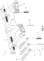
- the distractor device 1 comprises a longitudinal guiding or runner element 3, and a longitudinal driving element 5, such as a threaded rod, which may be arranged substantially parallel to the guiding element 3 such that the threaded rod may rotate about a rotation axis substantially parallel to the longitudinal axis of the guiding element 3.
- the threaded rod may be arranged to be rotated by a ratchet tool for example, or by any other suitable tool.
- the ratchet tool may be two-sided, so that a first side can be used to rotate a socket attached to the ratchet mechanism in a first direction, while a second side can be used to rotate the socket in a second direction. In this way the tool does not need to include a ratchet lever or other mechanism for changing the rotation direction of the socket. This simple construction is advantageous when washing and/or sterilising the tool.
- a first distractor arm 7 and a second distractor arm 9 are arranged to extend along a first, respectively second lateral axis from the guiding element 3.
- the first and second lateral axes are substantially orthogonal to the longitudinal axis of the guiding element 3.
- the first and second distractor arms 7, 9 are captively displaceable along the guiding element 3, such that the first and second distractor arms 7, 9 are displaceable away from each other by rotating the threaded rod 5 in a first rotational direction, and towards each other by rotating the threaded rod 5 in a second rotational direction, the second rotational direction being opposite to the first rotational direction.
- the threaded rod 5 may comprise a first threaded drive section 11 engaging with a corresponding thread of the first distractor arm 7, and a second threaded section 13 engaging with a corresponding thread of the second distractor arm 9.
- the threaded engagement of the first threaded section 11 with the first arm 7 may be opposite to the threaded engagement of the second threaded section 13 with the second arm 9, such that the first and second arms 7, 9 always move in opposite directions along the longitudinal axis when the threaded rod 3 is rotated.
- the first threaded section may have a right-hand thread, and the second threaded section a left-hand thread.
- Each of the first and second distractor arms 7, 9 may advantageously be provided in its distal region (the end of the arm which is not connected to the guiding element 3) with a fixation element or fixation head 15, 17 for securing the distal region to a first, respectively second bone of a joint to be distracted.
- the securing can be done by securing means such as bone screws, as explained later.
- the first and/or the second fixation element 15, 17 may be configured to be rotatable with a first and/or a second rotational degree of freedom with respect to its respective distractor arm.
- the first rotational degree of freedom is about a first fixation element axis substantially parallel to the longitudinal axis of the guiding element 3, for example, and the second rotational degree of freedom may be about a second fixation element axis substantially parallel to the longitudinal axis of the respective distractor arm 7, 9.
- the first and second fixation elements 15, 17 may be configured to be fixed with respect to the respective distractor arm 7, 9. Or they may have only one rotational degree of freedom. For example, when the distractor device 1 is used for hip distraction, the first rotational degree of freedom is sufficient.
- the first and/or second fixation elements 15, 17 may further comprise holding means 19 for fixing one or more bone screws to the fixation element 15, 17.
- the holding means 19 may advantageously be configured to permit a rotational adjustment of the bone screw(s) with at least one further rotational degree of freedom with respect to the fixation element 15, 17.
- the first and/or second degrees of rotational freedom may advantageously be provided by toothed or textured planar face-gears 21 or clutches, which can provide easy rotation when the opposing faces of the clutch are not pressed together, but which can be locked into the desired rotational position by forcing the faces together (eg by tightening a first clamping screw 23) to provide a very strong locked joint capable of transferring the large forces (eg 500N) required during the distraction.
- the clutches 21 may be provided with markers, to indicate the angle of rotation of one face with respect to the opposing face. In this manner it easy for the operator to ensure that the two fixation elements 15, 17 are set at the same angles, for example.
- the toothed faces may be arranged so that the joint can be set in discrete angular steps of equal magnitude, where the magnitude of each rotational step is preferably between 1 to 12 degrees, or more preferably between 4 and 8 degrees. In this specific example, one rotational step is substantially 6 degrees.
- the bone screws may be clamped to the fixation element 15, 17 using the screw clamp 25.
- One screw clamp may be configured to accommodate one, two or more bone screws.
- a second clamping screw 27 is provided for adjusting the screw clamp 25.
- a single second clamping screw may be used to clamp one, two or more bone screws.
- the first and second clamping screws 23, 27 can be designed so that they can be adjusted by the same tool that is used to rotate the driving element 5.
- a distractor device 1 according to one embodiment of the present invention has been described above.
- the device 1 is easily washable and sterilisable; it has a strong construction, so that it can withstand large forces required in the distraction process; and it is light in weight, so that it is easy to manoeuvre and does not impose significant rotational forces on the bones being distracted due to its weight.
- the main elements of the distractor device 1, ie the guiding element 3, the driving element 5 and the arms 7, 9, can be made of aluminium alloy, steel alloy, other alloy or nanostructured ceramic materials, for example.
- the U-shape of the distractor device 1 is also designed to leave an opening between the distractor arms 7, 9 to leave the distracted joint clear for X-raying.
- the cross-section of the guiding element 3 was shown to be substantially square or rectangular. This has the additional advantage that the strength of the guiding element can be further increased, while preventing any undesired rotation of the distractor arms 7, 9 relative to each other.
- the guiding element may be provided with a solid lubricant surface, such as a graphite coating.
- the distractor device 1 of Figures 4 and 5 shows an optional supporting element 6, which is configured around the guiding element 3 and has an opening for the driving element 5 to pass through it.
- the supporting element 6 may serve to support and/or stabilise the driving element 5 and thereby prevent it from buckling under the longitudinal compression load which is present in the driving element 5 when the distractor is in operation.
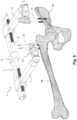
- a drill sleeve or guide 31 with a trocar 33 inside it is pushed through the flesh to reach a pelvic bone 34.
- the drill sleeve 31 is held in place with a handle 35 while the trocar 33 is withdrawn from the drill sleeve 31.
- the purpose of the drill sleeve is to protect the flesh during operation to provide a passage out for the drill waste.
- a hole can be drilled by a drill 36 into the pelvic bone 34 so that the drilling is done through the drill sleeve 31.
- a dedicated bone screw 37 in this example a cortical hip screw, is screwed into the hole in the pelvic bone 34.
- Other types of screws could be used instead, such as cancellous or cannulated screws.
- the screws 37 are made to sustain pressures preferably up to 1400 N/mm 2 .
- the distractor device 1 is put in place, at least approximately.
- the distance D as shown in Figure 4 is typically in the range of 10 cm to 14 cm, and more specifically about 12 cm.
- the clamping screws 23, 27 may be adjusted if necessary.
- the bone screw 37 is now slightly clamped by the second fixation element 17.
- Another incision on the patient's skin is made above the thigh bone 38.
- the drill sleeve 31 with the trocar 33 inside are now pushed through the flesh to reach the thigh bone 38.
- the drill sleeve 31 may be hold in place by the first fixation element 15 as shown in Figure 4 .
- the trocar 33 is then removed to allow the drill 36 to pass though the drill sleeve 31. Now the drilling can be done through the drill sleeve 31.
- the remaining two drilling operations can be done in the same manner through the remaining two screw channels in the first and second fixation elements 15, 17.
- the second clamping screws 27 can be tightened so that the fixation elements 15, 17 firmly clamp the clamping screws 37.
- the positions of the first and second fixation elements 15, 17 may be adjusted, so that the first and second fixation elements 15, 17 are preferably set at the same angles.
- the first and second distractor arms 7, 9 may be angled with respect to the first and second fixation elements. This angle may be for example +/-24 degrees or +/-36 degrees.
- the hip can be distracted by turning the drive element 5. In this manner both the first and second distractor arms 7, 9 are moved simultaneously and in opposite directions so that the distance between them is increased and thus the hip can be distracted.
- the hip can be returned to its normal state by bringing the distractor arms 7, 9 into a position where no force is exerted on the bones. Again, the distractor arms 7, 9 are moved by turning the driving element 5, but in the opposite direction compared to a situation, where the hip distraction took place.
- step 41 the bone screws 37 are drilled into the bones as explained above in more detail.
- step 43 the bone screws 37 are secured to the first and second fixations elements.
- step 45 the driving element is rotated in the first rotational direction to displace the first and second distractor arms 7, 9 away from each other for distracting the joint.
- step 47 an operation in the joint between the distracted bones is done.
- step 49 the driving element is rotated in the second rotational direction to bring the distractor arms 7, 9 closer to each other for bringing the bones again to their initial position.
- step 51 the distractor device 1 is released from the bone screws 37 and in step 53 the bone screws are removed from the bones.
- Invasive hip distraction with the invention obviates the need for distraction on a traction table, so the complications experienced in many known methods can be avoided or at least minimised.
- Sufficient hip distraction implies traction forces of about 250 to 500 N. Once the suction seal of the joint is broken, the force needed diminishes significantly. However, on a traction table, much of the traction force is lost in needlessly distracting the knee (about 5 mm) and ankle joints (another 5 mm). Also, on a traction table, the femoral head (ie the highest part of the thigh bone 38) has a tendency to slide anteriorly and reduce the anterior joint space because of the acetabular anteversion.
- the distractor device 1 once installed, may produce a traction force on the hip joint of 500 N, for example, without any unnecessary forces applied to other joints. This force is calculated in the elasticity of the dedicated cortical hip screws 37. Once this traction force is attained, the dedicated cortical hip screws 37 will be seen to start bending.
- the invention also permits a surgical intervention to be carried out without time pressure in order to attain the same degree of perfection as in open surgery. The results obtained are can therefore be as good as those of open surgery.
- the distractor device 1 allows the patient to lie on their side during the distraction operation and there is no need to raise patient's leg as in some known hip distraction methods.
- the handle 35 may be designed so that it may approximately have a T shape so that the cross bar of the T shape would have two or more holes to allow the drill sleeve to pass through.
- the cross bar could have for example three equally distanced holes.
- the T-shaped handle could be used, together with the drill sleeve 31 and drill 36, to drill the holes into the bones.
- the distractor device 1 would only be put in place once all the screws have been drilled into the bones.
Landscapes
- Health & Medical Sciences (AREA)
- Orthopedic Medicine & Surgery (AREA)
- Surgery (AREA)
- Life Sciences & Earth Sciences (AREA)
- Heart & Thoracic Surgery (AREA)
- Nuclear Medicine, Radiotherapy & Molecular Imaging (AREA)
- Engineering & Computer Science (AREA)
- Biomedical Technology (AREA)
- Medical Informatics (AREA)
- Molecular Biology (AREA)
- Animal Behavior & Ethology (AREA)
- General Health & Medical Sciences (AREA)
- Public Health (AREA)
- Veterinary Medicine (AREA)
- Neurology (AREA)
- Surgical Instruments (AREA)
Claims (14)
- Un dispositif distracteur articulaire (1) comprenant : un élément de guidage longitudinal (3), et un élément d'entraînement rotatif longitudinal (5) disposé sensiblement parallèlement à l'élément de guidage (3) de sorte que l'élément d'entraînement (5) puisse tourner autour d'un axe de rotation sensiblement parallèle à l'axe longitudinal de l'élément de guidage (3) ; un premier bras distracteur (7) et un second bras distracteur (9) tous deux reliés à l'élément moteur (5), le premier et le second bras distracteur (7, 9) s'étendant le long d'un premier, respectivement d'un second axe latéral de l'élément de guidage (3), le premier et le second axes latéraux étant sensiblement orthogonaux à l'axe longitudinal de l'élément de guidage (3), et le premier et le second bras distracteur (5, 7) pouvant être déplacés imperdablement le long de l'élément de guidage (3), caractérisé en ce que l'élément d'entraînement (5) est configuré pour éloigner le premier et le second bras distracteur (5, 7) l'un de l'autre le long dudit axe longitudinal en faisant tourner l'élément d'entraînement (5) dans un premier sens de rotation, et pour les rapprocher l'un de l'autre le long dudit axe longitudinal en faisant tourner l'élément d'entraînement (5) dans un second sens de rotation, le second sens de rotation étant opposé au premier sens de rotation.
- Dispositif distracteur (1) selon la revendication 1, dans lequel l'élément d'entraînement (5) est une tige filetée (5).
- Dispositif distracteur (1) selon la revendication 2, dans lequel la tige filetée (5) comprend une première section filetée (11) pour s'engager dans un filetage correspondant du premier bras distracteur (7), et une deuxième section filetée (13) pour s'engager dans un filetage correspondant du deuxième bras distracteur (9).
- Dispositif distracteur (1) selon la revendication 3, dans lequel l'engagement fileté de la première section filetée (11) avec le premier bras distracteur (7) est opposé à l'engagement fileté de la deuxième section filetée (13) avec le deuxième bras distracteur (9), de sorte que le premier et le deuxième bras distracteur (7, 9) sont conçus pour se déplacer dans des directions opposées le long de l'axe longitudinal lorsque la tige filetée (5) est tournée.
- Dispositif distracteur (1) selon la revendication 3 ou 4, dans lequel la première section filetée (11) a un filetage à droite et la deuxième section filetée (13) a un filetage à gauche.
- Dispositif distracteur (1) selon l'une quelconque des revendications précédentes, dans lequel chacun des premier et second bras distracteur (7, 9) comprend dans sa région distale un premier élément de fixation (15) et un second élément de fixation (17), respectivement, pour fixer la région distale à un premier os et à un second os, respectivement, d'une articulation à distraire.
- Dispositif distracteur (1) selon la revendication 6, dans lequel le premier et le deuxième élément de fixation (15, 17) sont configurés pour être rotatifs avec un premier degré de liberté de rotation par rapport à leur bras distracteur respectif (7, 9).
- Dispositif distracteur (1) selon la revendication 7, dans lequel le premier degré de liberté de rotation est autour d'un premier axe d'élément de fixation sensiblement parallèle à l'axe longitudinal de l'élément de guidage (3).
- Dispositif distracteur (1) selon l'une des revendications 7 à 8, dans lequel le premier et le deuxième élément de fixation (15, 17) sont configurés pour être rotatifs avec un deuxième degré de liberté de rotation par rapport à leur bras distracteur respectif (7, 9), le deuxième degré de liberté de rotation étant différent du premier degré de liberté de rotation.
- Dispositif distracteur (1) selon la revendication 9, dans lequel le deuxième degré de liberté de rotation est autour d'un deuxième axe d'élément de fixation sensiblement orthogonal à l'axe longitudinal de l'élément de guidage (3).
- Dispositif distracteur (1) selon l'une quelconque des revendications 6 à 10, dans lequel le premier et le deuxième élément de fixation (15, 17) comprennent des embrayages dentés ou texturés (21) pour assurer le premier et/ou le deuxième degré de liberté de rotation, les embrayages (21) étant conçus pour assurer la rotation lorsque les faces opposées de l'embrayage ne sont pas pressées l'une contre l'autre, mais étant conçus pour être verrouillés dans une position de rotation souhaitée en forçant les faces l'une contre l'autre.
- Dispositif distracteur (1) selon la revendication 11, dans lequel au moins certains des embrayages (21) sont munis de marqueurs pour indiquer un angle de rotation d'une face par rapport à sa face opposée.
- Dispositif distracteur (1) selon l'une quelconque des revendications 6 à 12, dans lequel le premier et le deuxième élément de fixation (15, 17) comprennent des moyens de maintien (19) pour fixer une ou plusieurs vis à os (36) aux éléments de fixation (15, 17).
- Dispositif distracteur (1) selon la revendication 13, dans lequel le moyen de maintien (19) est configuré pour permettre un ajustement en rotation de la ou des vis à os (36) avec au moins un autre degré de liberté en rotation par rapport au premier et au deuxième élément de fixation (15, 17).
Applications Claiming Priority (2)
| Application Number | Priority Date | Filing Date | Title |
|---|---|---|---|
| EP15186775 | 2015-09-24 | ||
| PCT/IB2015/059354 WO2017051226A1 (fr) | 2015-09-24 | 2015-12-04 | Dispositif distracteur et procédé |
Publications (3)
| Publication Number | Publication Date |
|---|---|
| EP3352683A1 EP3352683A1 (fr) | 2018-08-01 |
| EP3352683B1 true EP3352683B1 (fr) | 2024-02-07 |
| EP3352683C0 EP3352683C0 (fr) | 2024-02-07 |
Family
ID=54207330
Family Applications (1)
| Application Number | Title | Priority Date | Filing Date |
|---|---|---|---|
| EP15825822.8A Active EP3352683B1 (fr) | 2015-09-24 | 2015-12-04 | Dispositif distracteur |
Country Status (3)
| Country | Link |
|---|---|
| US (1) | US11357490B2 (fr) |
| EP (1) | EP3352683B1 (fr) |
| WO (1) | WO2017051226A1 (fr) |
Families Citing this family (14)
| Publication number | Priority date | Publication date | Assignee | Title |
|---|---|---|---|---|
| ES2978182T3 (es) | 2016-10-24 | 2024-09-06 | Paragon 28 Inc | Sistemas de osteotomía |
| GB2566559B (en) * | 2017-11-03 | 2020-03-11 | Qspine Ltd | Retractors |
| WO2020176889A1 (fr) * | 2019-02-28 | 2020-09-03 | Paragon 28, Inc. | Systèmes de fusion, instruments, plaques osseuses et procédés d'utilisation |
| EP4087505A4 (fr) * | 2020-04-09 | 2024-05-15 | Wright Medical Technology, Inc. | Gabarits, systèmes, et procédés de correction de déformations articulaires |
| US12383249B2 (en) | 2020-07-10 | 2025-08-12 | Warsaw Orthopedic, Inc. | Tissue retractor, retraction modules, and associated methods |
| US12349889B2 (en) | 2020-07-10 | 2025-07-08 | Warsaw Orthopedic, Inc. | Tissue retractor, retraction modules, and associated methods |
| US12096923B2 (en) | 2020-07-10 | 2024-09-24 | Warsaw Orthopedic, Inc. | Tissue retractor, retraction modules, and associated methods |
| US11350922B1 (en) | 2021-02-03 | 2022-06-07 | Warsaw Orthopedic, Inc. | Modular surgical instrument system and method for shank-based retraction and distraction |
| US11432852B1 (en) | 2021-03-22 | 2022-09-06 | Warsaw Orthopedic, Inc. | Screw shank based tissue retraction |
| WO2022224008A1 (fr) * | 2021-04-19 | 2022-10-27 | Ghiasi Hossein | Réduction fémorale fermée non radiologique et enclouage avec un clou supportant le poids pour fractures fémorales |
| CN113520514B (zh) * | 2021-07-20 | 2022-11-18 | 四川省医学科学院·四川省人民医院 | 一种改进的神经外科手术用的钻颅器 |
| CN114081553B (zh) * | 2021-12-22 | 2025-08-05 | 中国人民解放军总医院第一医学中心 | 一种神经牵拉外架 |
| CN115349933B (zh) * | 2022-08-23 | 2024-07-16 | 杭州华迈医疗科技有限公司 | 牵张成骨器 |
| CN119157616A (zh) * | 2024-08-26 | 2024-12-20 | 中国人民解放军总医院第四医学中心 | 一种基于增强现实辅助的骨折复位增强固定装置 |
Family Cites Families (11)
| Publication number | Priority date | Publication date | Assignee | Title |
|---|---|---|---|---|
| US1920821A (en) * | 1931-09-22 | 1933-08-01 | Wassenaar Jan Jacob Stephanus | Distraction bone forceps |
| GB1519139A (en) * | 1974-06-18 | 1978-07-26 | Crock H V And Pericic L | L securing elongate members to structurs more especially in surgical procedures |
| WO1990002527A1 (fr) | 1988-09-09 | 1990-03-22 | Australian Defence Industries Pty. Limited | Ecarteur spinal |
| US5219349A (en) | 1991-02-15 | 1993-06-15 | Howmedica, Inc. | Spinal fixator reduction frame |
| AU2003277287A1 (en) * | 2002-10-08 | 2004-05-04 | Warsaw Orthopedic, Inc. | Insertion device and techniques for orthopaedic implants |
| EP3222231A1 (fr) * | 2002-10-30 | 2017-09-27 | Zimmer Spine, Inc. | Insertion de système de stabilisation de la colonne vertébrale et procédés |
| US8702705B2 (en) | 2006-03-23 | 2014-04-22 | Bruce H. Ziran | Electromechanically driven external fixator and methods of use |
| US20080077155A1 (en) * | 2006-09-25 | 2008-03-27 | Jennifer Diederich | System and method for displacement of bony structures |
| US20100104999A1 (en) | 2008-10-23 | 2010-04-29 | Bulloch Scott E | Apparatus, System, and Method for Intra-Oral Distraction |
| US8062218B2 (en) * | 2009-02-27 | 2011-11-22 | Warsaw Orthopedic, Inc. | Surgical access instrument |
| US9131966B2 (en) * | 2013-03-11 | 2015-09-15 | DePuy Synthes Products, Inc. | Vertebral manipulation assembly |
-
2015
- 2015-12-04 EP EP15825822.8A patent/EP3352683B1/fr active Active
- 2015-12-04 WO PCT/IB2015/059354 patent/WO2017051226A1/fr not_active Ceased
- 2015-12-04 US US15/763,066 patent/US11357490B2/en active Active
Non-Patent Citations (1)
| Title |
|---|
| "Instructions for Use for HIP - FIX (Hip arthroscopy Instrument Set)", 2 September 2015, SWISS MEDICAL INSTRUMENTS AG, article ANDRÉ GASSER: "Instructions for Use for HIP - FIX (Hip arthroscopy Instrument Set)", XP055609558 * |
Also Published As
| Publication number | Publication date |
|---|---|
| EP3352683A1 (fr) | 2018-08-01 |
| WO2017051226A1 (fr) | 2017-03-30 |
| EP3352683C0 (fr) | 2024-02-07 |
| US20180271507A1 (en) | 2018-09-27 |
| US11357490B2 (en) | 2022-06-14 |
Similar Documents
| Publication | Publication Date | Title |
|---|---|---|
| US11357490B2 (en) | Distractor device and method | |
| US11103227B2 (en) | Spinal access retractor | |
| US5219349A (en) | Spinal fixator reduction frame | |
| CN107835666B (zh) | 外科手术仪器和使用方法 | |
| US7416553B2 (en) | Drill guide and plate inserter | |
| US8911364B2 (en) | Spine retractor and distractor device | |
| US8771282B2 (en) | Drill guide with rotating handle | |
| JP5314025B2 (ja) | 整形外科インプラントシステム | |
| EP2618754B1 (fr) | Système de support d'instrument chirurgical pour colonne vertébrale | |
| JP2021098062A (ja) | 手術器具および使用の方法 | |
| EP3047811B1 (fr) | Réducteur de tige | |
| US9439691B2 (en) | Fixation-based surgery | |
| KR20040106489A (ko) | 최소한으로 침투되는 삽입기구들 및 임플란트를 삽입하는방법 | |
| WO2006118999A2 (fr) | Instrument orthopedique | |
| CA2725332C (fr) | Dispositif et systeme de deplacement d'os | |
| US20220378408A1 (en) | Surgical instrument connectors and related methods | |
| AU2007313090A1 (en) | Orthopedic implant assembly | |
| US20180221034A1 (en) | System for Connecting a Connecting Device, in Particular a Distractor, to a Bone | |
| JP6871282B2 (ja) | 脊柱復位器具および脊柱復位システム | |
| CN100455272C (zh) | 侵入式牵引装置 | |
| US20260090826A1 (en) | Device and Surgical Technique for Foot Surgery | |
| CN109475372B (zh) | 脊柱矫正系统和方法 | |
| HK1079075B (en) | Minimally invasive instruments and methods for inserting implants |
Legal Events
| Date | Code | Title | Description |
|---|---|---|---|
| STAA | Information on the status of an ep patent application or granted ep patent |
Free format text: STATUS: THE INTERNATIONAL PUBLICATION HAS BEEN MADE |
|
| PUAI | Public reference made under article 153(3) epc to a published international application that has entered the european phase |
Free format text: ORIGINAL CODE: 0009012 |
|
| STAA | Information on the status of an ep patent application or granted ep patent |
Free format text: STATUS: REQUEST FOR EXAMINATION WAS MADE |
|
| 17P | Request for examination filed |
Effective date: 20180404 |
|
| AK | Designated contracting states |
Kind code of ref document: A1 Designated state(s): AL AT BE BG CH CY CZ DE DK EE ES FI FR GB GR HR HU IE IS IT LI LT LU LV MC MK MT NL NO PL PT RO RS SE SI SK SM TR |
|
| AX | Request for extension of the european patent |
Extension state: BA ME |
|
| DAV | Request for validation of the european patent (deleted) | ||
| DAX | Request for extension of the european patent (deleted) | ||
| STAA | Information on the status of an ep patent application or granted ep patent |
Free format text: STATUS: EXAMINATION IS IN PROGRESS |
|
| 17Q | First examination report despatched |
Effective date: 20190807 |
|
| STAA | Information on the status of an ep patent application or granted ep patent |
Free format text: STATUS: THE APPLICATION IS DEEMED TO BE WITHDRAWN |
|
| 18D | Application deemed to be withdrawn |
Effective date: 20210701 |
|
| 18RA | Request filed for re-establishment of rights before grant |
Effective date: 20220103 |
|
| STAA | Information on the status of an ep patent application or granted ep patent |
Free format text: STATUS: EXAMINATION IS IN PROGRESS |
|
| D18D | Application deemed to be withdrawn (deleted) | ||
| GRAP | Despatch of communication of intention to grant a patent |
Free format text: ORIGINAL CODE: EPIDOSNIGR1 |
|
| STAA | Information on the status of an ep patent application or granted ep patent |
Free format text: STATUS: GRANT OF PATENT IS INTENDED |
|
| RIC1 | Information provided on ipc code assigned before grant |
Ipc: A61B 90/00 20160101ALN20230628BHEP Ipc: A61B 17/66 20060101ALI20230628BHEP Ipc: A61B 17/64 20060101ALI20230628BHEP Ipc: A61B 17/02 20060101AFI20230628BHEP |
|
| INTG | Intention to grant announced |
Effective date: 20230711 |
|
| GRAS | Grant fee paid |
Free format text: ORIGINAL CODE: EPIDOSNIGR3 |
|
| GRAA | (expected) grant |
Free format text: ORIGINAL CODE: 0009210 |
|
| STAA | Information on the status of an ep patent application or granted ep patent |
Free format text: STATUS: THE PATENT HAS BEEN GRANTED |
|
| AK | Designated contracting states |
Kind code of ref document: B1 Designated state(s): AL AT BE BG CH CY CZ DE DK EE ES FI FR GB GR HR HU IE IS IT LI LT LU LV MC MK MT NL NO PL PT RO RS SE SI SK SM TR |
|
| REG | Reference to a national code |
Ref country code: CH Ref legal event code: EP |
|
| REG | Reference to a national code |
Ref country code: IE Ref legal event code: FG4D |
|
| REG | Reference to a national code |
Ref country code: DE Ref legal event code: R096 Ref document number: 602015087490 Country of ref document: DE |
|
| U01 | Request for unitary effect filed |
Effective date: 20240307 |
|
| U07 | Unitary effect registered |
Designated state(s): AT BE BG DE DK EE FI FR IT LT LU LV MT NL PT SE SI Effective date: 20240314 |
|
| PG25 | Lapsed in a contracting state [announced via postgrant information from national office to epo] |
Ref country code: IS Free format text: LAPSE BECAUSE OF FAILURE TO SUBMIT A TRANSLATION OF THE DESCRIPTION OR TO PAY THE FEE WITHIN THE PRESCRIBED TIME-LIMIT Effective date: 20240607 |
|
| PG25 | Lapsed in a contracting state [announced via postgrant information from national office to epo] |
Ref country code: GR Free format text: LAPSE BECAUSE OF FAILURE TO SUBMIT A TRANSLATION OF THE DESCRIPTION OR TO PAY THE FEE WITHIN THE PRESCRIBED TIME-LIMIT Effective date: 20240508 |
|
| PG25 | Lapsed in a contracting state [announced via postgrant information from national office to epo] |
Ref country code: RS Free format text: LAPSE BECAUSE OF FAILURE TO SUBMIT A TRANSLATION OF THE DESCRIPTION OR TO PAY THE FEE WITHIN THE PRESCRIBED TIME-LIMIT Effective date: 20240507 Ref country code: HR Free format text: LAPSE BECAUSE OF FAILURE TO SUBMIT A TRANSLATION OF THE DESCRIPTION OR TO PAY THE FEE WITHIN THE PRESCRIBED TIME-LIMIT Effective date: 20240207 |
|
| PG25 | Lapsed in a contracting state [announced via postgrant information from national office to epo] |
Ref country code: ES Free format text: LAPSE BECAUSE OF FAILURE TO SUBMIT A TRANSLATION OF THE DESCRIPTION OR TO PAY THE FEE WITHIN THE PRESCRIBED TIME-LIMIT Effective date: 20240207 |
|
| PG25 | Lapsed in a contracting state [announced via postgrant information from national office to epo] |
Ref country code: RS Free format text: LAPSE BECAUSE OF FAILURE TO SUBMIT A TRANSLATION OF THE DESCRIPTION OR TO PAY THE FEE WITHIN THE PRESCRIBED TIME-LIMIT Effective date: 20240507 Ref country code: NO Free format text: LAPSE BECAUSE OF FAILURE TO SUBMIT A TRANSLATION OF THE DESCRIPTION OR TO PAY THE FEE WITHIN THE PRESCRIBED TIME-LIMIT Effective date: 20240507 Ref country code: IS Free format text: LAPSE BECAUSE OF FAILURE TO SUBMIT A TRANSLATION OF THE DESCRIPTION OR TO PAY THE FEE WITHIN THE PRESCRIBED TIME-LIMIT Effective date: 20240607 Ref country code: HR Free format text: LAPSE BECAUSE OF FAILURE TO SUBMIT A TRANSLATION OF THE DESCRIPTION OR TO PAY THE FEE WITHIN THE PRESCRIBED TIME-LIMIT Effective date: 20240207 Ref country code: GR Free format text: LAPSE BECAUSE OF FAILURE TO SUBMIT A TRANSLATION OF THE DESCRIPTION OR TO PAY THE FEE WITHIN THE PRESCRIBED TIME-LIMIT Effective date: 20240508 Ref country code: ES Free format text: LAPSE BECAUSE OF FAILURE TO SUBMIT A TRANSLATION OF THE DESCRIPTION OR TO PAY THE FEE WITHIN THE PRESCRIBED TIME-LIMIT Effective date: 20240207 |
|
| PG25 | Lapsed in a contracting state [announced via postgrant information from national office to epo] |
Ref country code: PL Free format text: LAPSE BECAUSE OF FAILURE TO SUBMIT A TRANSLATION OF THE DESCRIPTION OR TO PAY THE FEE WITHIN THE PRESCRIBED TIME-LIMIT Effective date: 20240207 |
|
| PG25 | Lapsed in a contracting state [announced via postgrant information from national office to epo] |
Ref country code: PL Free format text: LAPSE BECAUSE OF FAILURE TO SUBMIT A TRANSLATION OF THE DESCRIPTION OR TO PAY THE FEE WITHIN THE PRESCRIBED TIME-LIMIT Effective date: 20240207 |
|
| PG25 | Lapsed in a contracting state [announced via postgrant information from national office to epo] |
Ref country code: SM Free format text: LAPSE BECAUSE OF FAILURE TO SUBMIT A TRANSLATION OF THE DESCRIPTION OR TO PAY THE FEE WITHIN THE PRESCRIBED TIME-LIMIT Effective date: 20240207 |
|
| PG25 | Lapsed in a contracting state [announced via postgrant information from national office to epo] |
Ref country code: CZ Free format text: LAPSE BECAUSE OF FAILURE TO SUBMIT A TRANSLATION OF THE DESCRIPTION OR TO PAY THE FEE WITHIN THE PRESCRIBED TIME-LIMIT Effective date: 20240207 |
|
| PG25 | Lapsed in a contracting state [announced via postgrant information from national office to epo] |
Ref country code: SK Free format text: LAPSE BECAUSE OF FAILURE TO SUBMIT A TRANSLATION OF THE DESCRIPTION OR TO PAY THE FEE WITHIN THE PRESCRIBED TIME-LIMIT Effective date: 20240207 |
|
| PG25 | Lapsed in a contracting state [announced via postgrant information from national office to epo] |
Ref country code: SM Free format text: LAPSE BECAUSE OF FAILURE TO SUBMIT A TRANSLATION OF THE DESCRIPTION OR TO PAY THE FEE WITHIN THE PRESCRIBED TIME-LIMIT Effective date: 20240207 Ref country code: SK Free format text: LAPSE BECAUSE OF FAILURE TO SUBMIT A TRANSLATION OF THE DESCRIPTION OR TO PAY THE FEE WITHIN THE PRESCRIBED TIME-LIMIT Effective date: 20240207 Ref country code: RO Free format text: LAPSE BECAUSE OF FAILURE TO SUBMIT A TRANSLATION OF THE DESCRIPTION OR TO PAY THE FEE WITHIN THE PRESCRIBED TIME-LIMIT Effective date: 20240207 Ref country code: CZ Free format text: LAPSE BECAUSE OF FAILURE TO SUBMIT A TRANSLATION OF THE DESCRIPTION OR TO PAY THE FEE WITHIN THE PRESCRIBED TIME-LIMIT Effective date: 20240207 |
|
| REG | Reference to a national code |
Ref country code: DE Ref legal event code: R097 Ref document number: 602015087490 Country of ref document: DE |
|
| PLBE | No opposition filed within time limit |
Free format text: ORIGINAL CODE: 0009261 |
|
| STAA | Information on the status of an ep patent application or granted ep patent |
Free format text: STATUS: NO OPPOSITION FILED WITHIN TIME LIMIT |
|
| 26N | No opposition filed |
Effective date: 20241108 |
|
| U20 | Renewal fee for the european patent with unitary effect paid |
Year of fee payment: 10 Effective date: 20250102 |
|
| PG25 | Lapsed in a contracting state [announced via postgrant information from national office to epo] |
Ref country code: MC Free format text: LAPSE BECAUSE OF FAILURE TO SUBMIT A TRANSLATION OF THE DESCRIPTION OR TO PAY THE FEE WITHIN THE PRESCRIBED TIME-LIMIT Effective date: 20240207 |
|
| PG25 | Lapsed in a contracting state [announced via postgrant information from national office to epo] |
Ref country code: IE Free format text: LAPSE BECAUSE OF NON-PAYMENT OF DUE FEES Effective date: 20241204 |
|
| U20 | Renewal fee for the european patent with unitary effect paid |
Year of fee payment: 11 Effective date: 20260102 |
|
| PG25 | Lapsed in a contracting state [announced via postgrant information from national office to epo] |
Ref country code: CY Free format text: LAPSE BECAUSE OF FAILURE TO SUBMIT A TRANSLATION OF THE DESCRIPTION OR TO PAY THE FEE WITHIN THE PRESCRIBED TIME-LIMIT; INVALID AB INITIO Effective date: 20151204 |
|
| REG | Reference to a national code |
Ref country code: CH Ref legal event code: U11 Free format text: ST27 STATUS EVENT CODE: U-0-0-U10-U11 (AS PROVIDED BY THE NATIONAL OFFICE) Effective date: 20260331 |
|
| PGFP | Annual fee paid to national office [announced via postgrant information from national office to epo] |
Ref country code: CH Payment date: 20260331 Year of fee payment: 11 |