EP3352882B1 - Multifunktionale akustische levitationsfalle - Google Patents
Multifunktionale akustische levitationsfalle Download PDFInfo
- Publication number
- EP3352882B1 EP3352882B1 EP16777602.0A EP16777602A EP3352882B1 EP 3352882 B1 EP3352882 B1 EP 3352882B1 EP 16777602 A EP16777602 A EP 16777602A EP 3352882 B1 EP3352882 B1 EP 3352882B1
- Authority
- EP
- European Patent Office
- Prior art keywords
- base
- protruding part
- spacer
- housing
- reflector
- Prior art date
- Legal status (The legal status is an assumption and is not a legal conclusion. Google has not performed a legal analysis and makes no representation as to the accuracy of the status listed.)
- Active
Links
Images



Classifications
-
- B—PERFORMING OPERATIONS; TRANSPORTING
- B01—PHYSICAL OR CHEMICAL PROCESSES OR APPARATUS IN GENERAL
- B01D—SEPARATION
- B01D43/00—Separating particles from liquids, or liquids from solids, otherwise than by sedimentation or filtration
-
- B—PERFORMING OPERATIONS; TRANSPORTING
- B01—PHYSICAL OR CHEMICAL PROCESSES OR APPARATUS IN GENERAL
- B01D—SEPARATION
- B01D49/00—Separating dispersed particles from gases, air or vapours by other methods
- B01D49/006—Separating dispersed particles from gases, air or vapours by other methods by sonic or ultrasonic techniques
-
- B—PERFORMING OPERATIONS; TRANSPORTING
- B01—PHYSICAL OR CHEMICAL PROCESSES OR APPARATUS IN GENERAL
- B01L—CHEMICAL OR PHYSICAL LABORATORY APPARATUS FOR GENERAL USE
- B01L3/00—Containers or dishes for laboratory use, e.g. laboratory glassware; Droppers
- B01L3/50—Containers for the purpose of retaining a material to be analysed, e.g. test tubes
- B01L3/502—Containers for the purpose of retaining a material to be analysed, e.g. test tubes with fluid transport, e.g. in multi-compartment structures
- B01L3/5027—Containers for the purpose of retaining a material to be analysed, e.g. test tubes with fluid transport, e.g. in multi-compartment structures by integrated microfluidic structures, i.e. dimensions of channels and chambers are such that surface tension forces are important, e.g. lab-on-a-chip
- B01L3/502761—Containers for the purpose of retaining a material to be analysed, e.g. test tubes with fluid transport, e.g. in multi-compartment structures by integrated microfluidic structures, i.e. dimensions of channels and chambers are such that surface tension forces are important, e.g. lab-on-a-chip specially adapted for handling suspended solids or molecules independently from the bulk fluid flow, e.g. for trapping or sorting beads or physically stretching molecules
-
- G—PHYSICS
- G01—MEASURING; TESTING
- G01N—INVESTIGATING OR ANALYSING MATERIALS BY DETERMINING THEIR CHEMICAL OR PHYSICAL PROPERTIES
- G01N15/00—Investigating characteristics of particles; Investigating permeability, pore-volume or surface-area of porous materials
- G01N15/10—Investigating individual particles
- G01N15/14—Optical investigation techniques, e.g. flow cytometry
- G01N15/1404—Handling flow, e.g. hydrodynamic focusing
-
- B—PERFORMING OPERATIONS; TRANSPORTING
- B01—PHYSICAL OR CHEMICAL PROCESSES OR APPARATUS IN GENERAL
- B01D—SEPARATION
- B01D21/00—Separation of suspended solid particles from liquids by sedimentation
- B01D21/28—Mechanical auxiliary equipment for acceleration of sedimentation, e.g. by vibrators or the like
- B01D21/283—Settling tanks provided with vibrators
-
- B—PERFORMING OPERATIONS; TRANSPORTING
- B01—PHYSICAL OR CHEMICAL PROCESSES OR APPARATUS IN GENERAL
- B01D—SEPARATION
- B01D51/00—Auxiliary pretreatment of gases or vapours to be cleaned
- B01D51/02—Amassing the particles, e.g. by flocculation
- B01D51/06—Amassing the particles, e.g. by flocculation by varying the pressure of the gas or vapour
- B01D51/08—Amassing the particles, e.g. by flocculation by varying the pressure of the gas or vapour by sound or ultrasound
-
- B—PERFORMING OPERATIONS; TRANSPORTING
- B01—PHYSICAL OR CHEMICAL PROCESSES OR APPARATUS IN GENERAL
- B01L—CHEMICAL OR PHYSICAL LABORATORY APPARATUS FOR GENERAL USE
- B01L2200/00—Solutions for specific problems relating to chemical or physical laboratory apparatus
- B01L2200/06—Fluid handling related problems
- B01L2200/0647—Handling flowable solids, e.g. microscopic beads, cells, particles
- B01L2200/0668—Trapping microscopic beads
-
- B—PERFORMING OPERATIONS; TRANSPORTING
- B01—PHYSICAL OR CHEMICAL PROCESSES OR APPARATUS IN GENERAL
- B01L—CHEMICAL OR PHYSICAL LABORATORY APPARATUS FOR GENERAL USE
- B01L2400/00—Moving or stopping fluids
- B01L2400/04—Moving fluids with specific forces or mechanical means
- B01L2400/0403—Moving fluids with specific forces or mechanical means specific forces
- B01L2400/0433—Moving fluids with specific forces or mechanical means specific forces vibrational forces
- B01L2400/0439—Moving fluids with specific forces or mechanical means specific forces vibrational forces ultrasonic vibrations, vibrating piezo elements
-
- G—PHYSICS
- G01—MEASURING; TESTING
- G01N—INVESTIGATING OR ANALYSING MATERIALS BY DETERMINING THEIR CHEMICAL OR PHYSICAL PROPERTIES
- G01N15/00—Investigating characteristics of particles; Investigating permeability, pore-volume or surface-area of porous materials
- G01N15/10—Investigating individual particles
- G01N15/1023—Microstructural devices for non-optical measurement
-
- G—PHYSICS
- G01—MEASURING; TESTING
- G01N—INVESTIGATING OR ANALYSING MATERIALS BY DETERMINING THEIR CHEMICAL OR PHYSICAL PROPERTIES
- G01N15/00—Investigating characteristics of particles; Investigating permeability, pore-volume or surface-area of porous materials
- G01N15/10—Investigating individual particles
- G01N15/14—Optical investigation techniques, e.g. flow cytometry
- G01N15/149—Optical investigation techniques, e.g. flow cytometry specially adapted for sorting particles, e.g. by their size or optical properties
-
- G—PHYSICS
- G01—MEASURING; TESTING
- G01N—INVESTIGATING OR ANALYSING MATERIALS BY DETERMINING THEIR CHEMICAL OR PHYSICAL PROPERTIES
- G01N15/00—Investigating characteristics of particles; Investigating permeability, pore-volume or surface-area of porous materials
- G01N2015/0038—Investigating nanoparticles
-
- G—PHYSICS
- G01—MEASURING; TESTING
- G01N—INVESTIGATING OR ANALYSING MATERIALS BY DETERMINING THEIR CHEMICAL OR PHYSICAL PROPERTIES
- G01N15/00—Investigating characteristics of particles; Investigating permeability, pore-volume or surface-area of porous materials
- G01N15/10—Investigating individual particles
- G01N2015/1028—Sorting particles
-
- G—PHYSICS
- G01—MEASURING; TESTING
- G01N—INVESTIGATING OR ANALYSING MATERIALS BY DETERMINING THEIR CHEMICAL OR PHYSICAL PROPERTIES
- G01N15/00—Investigating characteristics of particles; Investigating permeability, pore-volume or surface-area of porous materials
- G01N15/10—Investigating individual particles
- G01N15/14—Optical investigation techniques, e.g. flow cytometry
- G01N15/1404—Handling flow, e.g. hydrodynamic focusing
- G01N2015/142—Acoustic or ultrasonic focussing
Definitions
- the present invention pertains to the field of device for manipulating particles in a fluid.
- the present invention relates to a device suitable for use as an acoustic resonator for manipulating particles in a fluid by means of acoustic waves.
- Acoustic waves can be used to handle or sort particles in a fluid by means of an acoustic force field.
- acoustic resonators comprises a cavity wherein one of the walls comprises an acoustic wave generator and the opposing wall serves as passive reflector.
- the ultrasonic wave generated is reflected and the wave superposition is known as a standing wave: at least one acoustic pressure node is created at a given positon along a dimension of a cavity of an acoustic resonator by providing a resonance condition for the acoustic wave.
- Particles manipulation with ultrasonic standing waves is known as a powerful tool for handling, moving or trapping particles in microfluidics devices.
- US patent 7,373,805 discloses an acoustic resonator comprising an ultrasonic transducer glued to a coupling plate, an acoustic resonator and a spacer arranged between the coupling plate and the acoustic resonator and defining a resonant cavity.
- the coupling plate, the spacer and the acoustic resonator are held in place between a base and a top plate secured with screws.
- the screws must be strongly tightened in order to limit leakages of fluid filling the resonant cavity.
- the screwing between the base and the top plate, which defined the thickness of the resonant cavity must be precisely controlled in order to ensure a regular thickness.
- US patent application 2013/0327130 also discloses acoustic resonators comprising four layers: a transducer, a coupling steel layer, a spacer and an acoustic reflector.
- the spacer is assembled in sandwich between the coupling steel layer and the acoustic reflector with neoprene glue. Therefore, the resonator disclosed in US 2013/0327130 cannot be reused; especially the spacer cannot be changed in order to change the size of the resonant cavity.
- the device of the invention may be used with living objects, there is a particular need for a device which may be easily disassembled and cleaned, e.g. autoclaved.
- the acoustic resonators of the prior art are designed for handling only a small amount of particles -from 1 to several hundred- within microfluidic devices.
- US 7,373,805 discloses indeed the use of particles of diameter in the order of 1 ⁇ m and US 2013/03271430 discloses that the particles have an average size of about 50 nm to about 5 ⁇ m.
- the present invention relates to a device, suitable for use as an acoustic resonator, comprising a base, at least one acoustic wave generator coupled to the base (2), a spacer comprising an aperture and a reflector, wherein:
- the base, the spacer and the housing are held in place due to the protruding part of the base inserted within the apertures of the spacer and the housing without glue.
- the spacer may thus be easily replaced and the resonant cavity may be accessed.
- the device of the present invention avoids leakage of fluid as the fluid should follow a tortuous path to flow out of the resonant cavity.
- the protruding part is axisymmetric, preferably cylindrical, rhombohedral, parallelepiped or ribbon-shaped.
- the device further comprises a supporting base and a top part, wherein the base, the spacer, the housing and the reflector are held in position between the supporting base and the top part.
- the supporting base extends outwardly from the base; the top part encompasses the base, the spacer, the housing and the reflector; and the supporting base and the top plate are secured together, for instance with screws.
- the device further comprises a gasket ensuring tightness between the supporting base and the top part.
- the protruding part comprises at least one inlet and at least one outlet.
- the base, the protruding part and/or the housing comprises a material selected from metal or plastic.
- the reflector comprises an optically transparent material selected from glass, quartz or plastic.
- the protruding part comprises an optically transparent material selected from glass, quartz or plastic.
- the top part comprises at the top an optically transparent window.
- the spacer comprises a material selected from polyimide or a polyethylene terephthalate.
- the present invention also relates to an acoustic resonator comprising the device according to the invention and at least one acoustic wave generator coupled to the base.
- the at least one acoustic wave generator is located below the protruding part of the base.
- the at least one acoustic wave generator is an ultrasonic wave generator.
- the at least one acoustic wave generator is a piezo transducer.
- the at least one acoustic wave generator is ring-shaped.
- the present invention further relates to a method of trapping particles in a fluid according to claim 14.
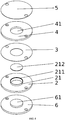
- this invention relates to a device 1 , suitable for use as an acoustic resonator, comprising a base 2 adapted to be coupled to at least one acoustic wave generator, a spacer 3 comprising an aperture 31 and a reflector 5 , wherein:
- the housing 4 is positioned between the spacer 3 and the reflector 5 , thereby arranging a cavity between the protruding part 21 and the reflector 5 ; such cavity having a thickness identical to that of the inner edge of the spacer 3.
- the protruding part 21 is inserted within the aperture of the spacer 31 and the aperture of the housing 41.
- the base 2 is a plate. According to one embodiment, the base 2 is adapted to be a coupling layer between a resonant cavity and the at least one acoustic wave generator. According to one embodiment, the base 2 is cylindrical (i.e. has a circular periphery).
- the base 2 comprises a protruding part 21 protruding upwardly from the base 2.
- the protruding part 21 has a constant thickness.
- the thickness of the protruding part 21 is ranging from 1 to 10 mm, preferably from 2 to 5 mm.
- the protruding part 21 is hollow and comprises a peripheral groove 211 configured to accommodate a bottom plate 212 , acting as the bottom plate of the cavity.
- Said bottom plate 212 has a thickness t.
- the thickness t of the bottom plate 212 is ranging from 1 to 10 mm, preferably from 2 to 5 mm.
- said peripheral groove 211 comprises an O-ring configured to ensure tightness of the cavity.
- the protruding part 21 is axisymmetric. According to one embodiment, the protruding part 21 is cylindrical, rhombohedral, parallelepiped or ribbon-shaped.
- the area of the protruding part 21 is ranging from 1 to 10 cm 2 , preferably from 1 to 3 cm 2 .
- the base 2 comprises at least one protruding part 21. According to one embodiment, the base 2 comprises more than one protruding part 21. According to one embodiment, the base 2 comprises more than one hollow protruding part 21 , each comprising a bottom plate 212.
- the spacer 3 is a plate. According to one embodiment, the spacer 3 is a plate having a constant thickness. According to one embodiment, the spacer 3 is cylindrical (i.e. has a circular periphery). According to one embodiment, the thickness of the spacer 3 is ranging from 10 ⁇ m to 2000 ⁇ m, preferably from 50 ⁇ m to 1000 ⁇ m, more preferably from 50 to 500 ⁇ m.
- the spacer 3 comprises an aperture 31.
- the aperture of the spacer 31 is complementary to the protruding part 21.
- the shape of the aperture of the spacer 31 is complementary to the shape of the protruding part 21.
- the aperture of the spacer 31 has a shape adapted to cooperate with the protruding part 21.
- the aperture of the spacer 31 has the same shape as the protruding part 21 , such that the protruding part 21 may be inserted through the aperture of the spacer 31 without mechanical play, the spacer 3 lying on the base 2. Due to the protruding part 21 , the spacer 3 is locked in translation in the plane of the base 2. According to one embodiment, the shape of the protruding part 21 prevents rotation of the spacer 3 relative to the base 2.
- the protruding part 21 is not cylindrical but may be rhombohedral, parallelepiped or ribbon-shaped.
- the spacer 3 and the protruding part 21 does not exhibit the same thickness.
- the thickness of the spacer 3 is smaller than the thickness of the protruding part 21.
- the ratio between the thickness of the spacer 3 and the thickness of the protruding part 21 is lower than 0.5.
- the ratio between the thickness of the spacer 3 and the thickness of the protruding part 21 is ranging from 0.001 to 0.5, preferably from 0.005 to 0.2, preferably about 0.01.
- the spacer 3 comprises a material selected from polyimide or polyethylene terephthalate.
- the spacer 3 comprises at least one aperture 31. According to one embodiment, the spacer 3 comprises more than one aperture 31.
- the reflector 5 is a plate. According to one embodiment, the reflector 5 has a constant thickness. According to one embodiment, the reflector 5 is cylindrical (i.e. has a circular periphery). According to one embodiment, the reflector 5 does not comprise any aperture. According to one embodiment, the thickness of the reflector 5 is ranging from 500 ⁇ m to 4 mm, preferably from 1 mm to 2 mm.
- the reflector 5 comprises a material chosen among: organic or mineral glasses, quartz, thermoplastic materials or metallic alloys. According to one embodiment, the reflector 5 is made from titanium alloy such as TA6V. According to one embodiment, the reflector 5 comprises an optically transparent material. According to one embodiment, the reflector 5 comprises an opaque material.
- the housing 4 is a plate. According to one embodiment, the housing 4 has a constant thickness, especially the inner edge of the aperture 41 has a constant thickness. According to one embodiment, the thickness of the housing 4 , especially the thickness of the inner edge of the aperture 41 has the same thickness t than the thickness of the protruding part of the base 21. According to one embodiment, the housing 4 is cylindrical (i.e. has a circular periphery). According to one embodiment, the housing 4 comprises an aperture 41. According to one embodiment, the thickness of the housing 4 is ranging from 1 to 10 mm, preferably from 2 to 5 mm.
- the aperture of the housing 41 is complementary to the protruding part 21.
- the shape of the aperture of the housing 41 is complementary to the shape of the protruding part 21.
- the aperture of the housing 41 is adapted to cooperate with the protruding part 21.
- the aperture of the housing 41 has the same shape as the protruding part 21 , such that the protruding part 21 may be inserted within the aperture of the housing 41 without mechanical play, the housing 4 lying on the spacer 3. Due to the protruding part 21 , the housing 4 is locked in translation along the plane of the base 2.
- the shape of the protruding part 21 prevents rotation of the housing 4 relative to the base 2.
- the protruding part 21 is not cylindrical but may be rhombohedral, parallelepiped or ribbon-shaped.
- the housing 4 comprises at least one aperture 41. According to one embodiment, the housing 4 comprises more than one aperture 41.
- the base 2 , the protruding part 21 and/or the housing 4 comprises a material selected among: organic or mineral glasses, quartz, thermoplastic materials, metal such as for instance aluminum or stainless steel.
- the base 2 , the protruding part 21 , the housing 4 and/or the reflector 5 comprises or consist of a material having high acoustic impedance, preferably ten times greater than the acoustic impedance of the fluid filing the resonant cavity.
- the protruding part 21 and the reflector 5 are made from different materials.
- the protruding part 21 and the reflector 5 are made from the same material.
- the protruding part 21 is made of an optically transparent material. According to one embodiment, the protruding part 21 is made of a material chosen among: organic or mineral glasses, quartz or thermoplastic materials.
- said bottom plate 212 is made of an optically transparent material.
- said bottom plate 212 is made of a silicon wafer.
- said bottom plate 212 is made of a material chosen among: organic or mineral glasses, quartz or thermoplastic materials.
- the device comprises successively the base 2 , the spacer 3 , the housing 4 and the reflector 5 ; with the protruding part of the base 21 inserted within the aperture of the spacer 31 and the aperture of the housing 41 , such that the device comprises a cavity between the protruding part 21 and the reflector 5 , the said cavity having the same thickness than the thickness of the spacer 3.
- the said cavity has a volume ranging from 200 ⁇ L to 2000 ⁇ L, preferably from 1000 ⁇ L to 2000 ⁇ L.
- volume of cavity more than one thousand, preferably more than hundreds of thousands of particles may be manipulated.
- such dimensions of cavity enable to manipulate micron-sized particles.
- the upper and lower wall of the cavity i.e. the upper surface of the protruding part and the lower surface of the reflector
- the spacer 3 and/or the housing 4 do not have a constant thickness so that the upper and lower wall of the cavity (i.e. the upper surface of the protruding part and the lower surface of the reflector) are not parallel.
- the spacer 3 and the housing 4 are not glued together; the spacer 3 may be easily changed in order to change the thickness of the cavity.
- the housing 4 comprises a peripheral wall 42 protruding upwardly for encasing the reflector 5 without mechanical play.
- the reflector 5 lies on the housing 4.
- the reflector 5 is not glued to the housing 4.
- the reflector 5 is glued or fixed to the housing 4.
- the reflector may lie on the housing and be maintained by capillary forces without glue or fixation means.
- the device further comprises a supporting base 6 and a top part 7 enclosing together the base 2 , the spacer 3 , the housing 4 and the reflector 5 , preferably without mechanical play.
- the base 2 , the spacer 3 , the housing 4 and the reflector 5 are held in position between the supporting base 6 and the top part 7.
- the supporting base 6 extends downwardly and outwardly from the base 2.
- the top part 7 encompasses the base 2 , the spacer 3 , the housing 4 and the reflector 5.
- the supporting base 6 and the top plate 7 are secured together, for instance with screws.
- the device further comprises a gasket 8 ensuring tightness between the supporting base 6 and the top part 7.
- the top part 7 comprises at the top an optically transparent window.
- the cavity can be observed thought the optically transparent window with an electronic microscope in order, for example, to study the acoustic interaction between particles.
- the device 1 further comprises a supporting base 6 comprising a protruding part 61 having a shape complementary to the shape of the protruding part 21 of the base 2 , so that the protruding part 61 of the supporting base 6 may be inserted within the protruding part 21 of the base 2.
- the acoustic wave generator when an acoustic wave generator is fixed to the protruding part of the supporting base 61 , the acoustic wave generator may be coupled to the protruding part of the base 21.
- the device does not comprises a top part 7 and the supporting base 6 , the housing 4 and the base 2 are bolted, screwed or maintained by any means known by one skilled in the art.
- the protruding part of the supporting base 61 is made of an optically transparent material.
- the protruding part of the supporting base 61 is made of a material chosen among: organic or mineral glasses, quartz or thermoplastic materials.
- the protruding part 21 comprises at least one inlet 22 and at least one outlet 23.
- said inlet 22 and outlet 23 are suitable for filing the cavity and/or for creating a flow of fluid within the cavity.
- the base and/or the supporting base comprises an inlet channel and an outlet channel, fluidly connected to respectively the inlet and the outlet of the protruding part.
- the inlet 22 and the outlet 23 are not located at the center of the protruding part 21.
- the flow rate depends on the particles to be manipulated, the cavity volume and the acoustic force field applied. For example, the fluid may flow at a flow rate ranging from 0.01 mL/min to 100 mL/min.
- the fluid is a liquid.
- the liquid is selected from a water-based liquid, an organic liquid, a biological liquid such as blood plasma, a tissue culture media such as LB (Lysogeny Broth) basic growing bacteria culture medium, a ionic liquid or complex fluids such as polymeric solutions leading to scaffold fabrication.
- the bottom plate may comprise at least one inlet and at least one outlet suitable for filing the cavity and/or for creating a flow of fluid within the cavity.
- the protruding part 21 does not comprise any inlet or outlet.
- the device is used for analysis e.g. of a drop or drops of a solution disposed in the cavity without any flow (i.e. before positioning the reflector on the housing).
- the protruding part 21 comprises at least two inlets: at least on inlet introduces the sample and at least one inlet introduces a reactive (e.g. for cleaning, diluting or testing the sample).
- the protruding part 21 comprises at least two outlets. According to one embodiment, each outlet is fluidly connected to valves which open or close depending of the sample to be collected.
- the thickness of the protruding part 21 about one outlet is different from the thickness of the protruding part 21 about the other outlet.
- the protruding part 21 comprises a plurality of separators 24 , such as for instance pins, protruding upwardly such that the resonant cavity comprises a plurality of compartments in fluid communication between each other.
- the separator has a thickness equal or lower than the thickness of the inner edge of the spacer 3.
- each compartment is adapted to be couple with an acoustic wave generator.
- the said compartments may have different thicknesses, or may be used with different mediums, different frequencies and/or different acoustic wave generators.
- the base in order to parallelize the manipulation of particles, may comprises more than one protruding part and the spacer and the housing may comprise more than one aperture complementary to the protruding parts.
- different particles may be manipulated or the same particles may be manipulated within different fluids.
- the invention also relates to an acoustic resonator 11 comprising the device 1 according to the invention and at least one acoustic wave generator 9 coupled to the base.
- the at least one acoustic wave generator is cylindrical, square-shaped, rod-shaped or ring-shaped.
- the at least one acoustic wave generator 9 is glued or fixed to the base 2.
- the at least one acoustic wave generator 9 is glued or fixed to the protruding part 61 of the supporting base 6.
- the height of the protruding part 61 is configured so that when at least one acoustic wave generator 9 is glued or fixed to said protruding part 61 , the at least one acoustic wave generator 9 is coupled to the protruding part 21.
- Said coupling may be a dry coupling or may use any coupling means.
- the at least one acoustic wave generator 9 is located below the protruding part of the base 21. According to one embodiment, a plurality of acoustic wave generators 9 is located below the protruding part of the base 21. According to one embodiment, the base 2 is etched on the back of the protruding part 21 for encasing the at least one acoustic wave generator 9.
- the at least one acoustic wave generator 9 is located at the top of the protruding part of the supporting base 61. According to one embodiment, a plurality of acoustic wave generators 9 is located at the top of the protruding part of the supporting base 61.
- the at least one acoustic wave generator 9 is an ultrasonic wave generator. According to one embodiment, the at least one acoustic wave generator 9 is a piezo transducer.
- the area of the optically transparent part of the reflector 5 is larger than the area of the at least one acoustic wave generator, thereby enabling to investigate upstream and downstream of the acoustic force field.
- the reflector 5 , the protruding part 21 of the base 2 and the protruding part 61 of the supporting base 6 comprises an optically transparent material
- the at least one acoustic wave generator 9 is at least one ring-shaped acoustic wave generator. Said embodiment enables optical analysis of the cavity by means of transmission microscopy.
- the invention also relates to a method of trapping particles in a fluid using the device according to the invention.
- the method of trapping particles in a fluid comprises the steps of:
- the method of trapping particles may be implemented without flow of fluid or with continuous or pulsatile flow of fluid.
- the trapping of particles may be implemented by levitation, selective focusing, MSF, flow trapping sorting or selective focusing trapping. Therefore, the acoustic resonator of the invention is a multi-use acoustic trap, preferably a multi-use acoustic levitation trap. According to one preferred embodiment, the trapping of particles may be implemented by levitation.
- Levitation is generated by acoustic standing waves, preferably ultrasonic standing waves originating an ultrasonic radiation pressure profile characterized by nodes and antinodes in the cavity thickness.
- Nodes and antinodes can be placed anywhere within the cavity thickness, even close to walls.
- the radiation force that is a focusing force pulls particles away from the walls preventing particle-wall interactions.
- the nodal position can be modified by moving it in controlled way toward the walls: the equilibrium position of the particles can thus be modulated through the whole cavity thickness.
- the acoustic resonator of the invention may be used with non-living particles and with living particles such as for instance cells, bacteria, viruses, DNA, proteins and the like.
- the particles are nano- or micron-sized particles, i.e. having at least one size ranging from 0.1 to few hundreds micrometers, preferably 0.1 to 900 ⁇ m, more preferably from 1 to 500 ⁇ m, even more preferably from 10 to 400 ⁇ m.
- the particles to be manipulated or trapped are selected from rigid, elastic, mineral or biological particles.
- the particles to be manipulated or trapped are selected from algae, microorganisms, bacteria, viruses, DNA, proteins or leavening.
- the particles to be manipulated or trapped are selected from colloidal emulsion, non-colloidal emulsions, ionic fluids or active fluids.
- the particles to be manipulated or trapped are selected from cells, parts of cells such as cell debris, or cluster of cells; such as for instance blood cells, cancellous cells or epithelial cells.
- the particles to be manipulated or trapped are selected from phospholipids, liposomes or vesicles.
- the particles to be manipulated or trapped are selected from micro-particles such as metallic microfibers; or nanoparticles such as carbon nanotubes or mixture thereof.
- the method of trapping particles is implemented with self-propelled objects such as bacteria in biological or ionic fluids or micro-/nano-robots.
- the fluid comprising the particles is an organic or an inorganic fluid.
- the upper surface of the protruding part and/or the lower surface of the reflector may comprise a sensing medium enabling detection of particles.
- the upper surface of the protruding part and/or the lower surface of the reflector may be labelled with specific antibodies in order to trap specific cells labeled with surface antigen receptors flowing through the cavity, either by an imposed flow or by the flow generated by the acoustic force field.
- the acoustic resonator of the invention may be used in tissue engineering by aggregating and manipulating different cells.
- the method of trapping may also comprises the step of aggregating the particles for the fabrication of two- or three-dimensional constructs, for instance for producing filters.
- the device of the invention and/or the acoustic resonator of the invention is temperature controlled by any means known by one skilled in the art such as for instance a Pelletier system or a heating circuit within the base.
- Bacteria suspension is injected within the cavity of the acoustic resonator of the present invention.
- concentration of bacteria may vary from high concentration to very diluted samples.
- An acoustic force field is implemented within the cavity by means of the acoustic wave generator and several thousands or millions of bacteria are trapped under the acoustic force field, thereby inducing a stable aggregate in levitation.
- a stable colony of bacteria can therefore be studied by observing its time evolution in function of the suspending medium.
- the entire colony can be trapped and the medium modified in order to establish new equilibriums. It is also possible within the present acoustic resonator to eliminate specific bacteria by modifying the medium.
- the cavity may be demounted and the sample may be collected after the assay in order to be submitted to other studies with any technique known to one skilled in the art.
- Example 2 Separation of particulate species
- a suspension comprising different species or different concentrations of species is injected within the cavity of the acoustic resonator of the present invention.
- Species could differ on size or even on acoustic properties such as acoustic impedance.
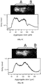
- a suspension of two species of polystyrene particles of 7 ⁇ m diameter (A) and of 2 ⁇ m diameter (B) are injected within the cavity.
- the different species are trapped and positioned at different distances from the walls of the cavity. Once different equilibrium positions have been reached, a flow is established in such a way that only one kind species remains trapped while the other(s) are eluted, and the sample collected is filtered of the trapped species.
- acoustic force depends on particles size, acoustic force is much stronger for bigger species, at least 40 times stronger for species of 7 ⁇ m diameter relative to species of 2 ⁇ m diameter. Therefore, two effects are used: a) the time required for species to reach the equilibrium position is much smaller for bigger species; and b) the force to keep trapped bigger species is much stronger.
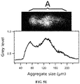
- Figures 5 illustrate the density profile with peaks corresponding to the two species. Especially, figures 5A, 5B , 5C, 5D and 5E show successively the different positions of both species, after respectively 0, 2, 3, 4 and 5 seconds.
Landscapes
- Chemical & Material Sciences (AREA)
- Health & Medical Sciences (AREA)
- Chemical Kinetics & Catalysis (AREA)
- Physics & Mathematics (AREA)
- Dispersion Chemistry (AREA)
- Analytical Chemistry (AREA)
- General Health & Medical Sciences (AREA)
- Clinical Laboratory Science (AREA)
- Hematology (AREA)
- Fluid Mechanics (AREA)
- Life Sciences & Earth Sciences (AREA)
- Biochemistry (AREA)
- General Physics & Mathematics (AREA)
- Immunology (AREA)
- Pathology (AREA)
- Investigating Or Analyzing Materials By The Use Of Ultrasonic Waves (AREA)
- Separation Of Solids By Using Liquids Or Pneumatic Power (AREA)
- Physical Or Chemical Processes And Apparatus (AREA)
Claims (14)
- Vorrichtung (1), die zur Verwendung als ein akustischer Resonator geeignet ist, umfassend einen Boden (2), mindestens einen Akustikwellengenerator, der mit dem Boden (2) gekoppelt ist, einen Abstandshalter (3), der eine Öffnung (31) umfasst, und einen Reflektor (5);
dadurch gekennzeichnet, dass:- der Boden (2) einen vorspringenden Teil (21) umfasst, der eine Dicke t aufweist;- der vorspringende Teil (21) mindestens einen Einlass (22) und mindestens einen Auslass (23) umfasst;- die Öffnung des Abstandshalters (31) zum vorspringenden Teil des Bodens (21) komplementär ist;- die Vorrichtung (1) weiter ein Gehäuse (4) umfasst, das eine Öffnung (41) aufweist, die zum vorspringenden Teil des Bodens (21) komplementär ist, und wobei der innere Rand der Öffnung (41) dieselbe Dicke t aufweist wie der vorspringende Teil (21); und- das Gehäuse (4) derart zwischen dem Abstandshalter (3) und dem Reflektor (5) positioniert ist, dass die Dicke des inneren Rands des Abstandshalters (3) die Dicke eines Hohlraums zwischen dem vorspringenden Teil (21) und dem Reflektor (5) definiert. - Vorrichtung nach Anspruch 1, wobei der vorspringende Teil (21) achsensymmetrisch, vorzugsweise zylindrisch, rhomboedrisch, parallelepiped oder bandförmig ist.
- Vorrichtung nach Anspruch 1 oder 2, weiter einen Tragsockel (6) und ein Oberteil (7) umfassend, wobei der Boden (2), der Abstandshalter (3), das Gehäuse (4) und der Reflektor (5) zwischen dem Tragsockel (6) und dem Oberteil (7) in Position gehalten werden.
- Vorrichtung nach Anspruch 3, wobei sich der Tragsockel (6) vom Boden (2) nach außen erstreckt; das Oberteil (7) den Boden (2), den Abstandshalter (3), das Gehäuse (4) und den Reflektor (5) umschließt; und der Tragsockel (6) und die Oberplatte (7) aneinander gesichert sind, zum Beispiel mit Schrauben.
- Vorrichtung nach Anspruch 3 oder 4, weiter eine Dichtung (8) umfassend, die Dichtigkeit zwischen dem Tragsockel (6) und dem Oberteil (7) sicherstellt.
- Vorrichtung nach einem der Ansprüche 1 bis 5, wobei der Boden (2), der vorspringende Teil (21) und/oder das Gehäuse (4) ein Material umfasst, ausgewählt aus Metall oder Kunststoff.
- Vorrichtung nach einem der Ansprüche 1 bis 6, wobei der Reflektor (5) ein optisch transparentes Material umfasst, ausgewählt aus Glas, Quarz oder Kunststoff.
- Vorrichtung nach einem der Ansprüche 1 bis 7, wobei der vorspringende Teil (21) ein optisch transparentes Material umfasst, ausgewählt aus Glas, Quarz oder Kunststoff.
- Vorrichtung nach einem der Ansprüche 1 bis 8, wobei das Oberteil (7) an der Oberseite ein optisch transparentes Fenster umfasst.
- Vorrichtung nach einem der Ansprüche 1 bis 9, wobei der Abstandshalter (3) ein Material umfasst, ausgewählt aus Polyimid oder einem Polyethylenterephthalat.
- Akustischer Resonator (8), der die Vorrichtung nach einem der Ansprüche 1 bis 10 und mindestens einen Akustikwellengenerator (9) umfasst, der mit dem Boden gekoppelt ist.
- Akustischer Resonator nach Anspruch 11, wobei der mindestens eine Akustikwellengenerator (9) unter dem vorspringenden Teil des Bodens (21) lokalisiert ist.
- Akustischer Resonator nach Anspruch 11 oder Anspruch 12, wobei der mindestens eine Akustikwellengenerator (9) ein Ultraschallwellengenerator oder ein Piezo-Wandler oder ringförmig ist.
- Verfahren zum Einfangen von Partikeln in einem Fluid, umfassend die Schritte des:i. Bereitstellens eines akustischen Resonators (11), welcher umfasst:- mindestens einen Akustikwellengenerator (9) zum Erzeugen einer Schallwelle einer Frequenz f;- einen Boden (2), der dazu geeignet ist, mit dem mindestens einen Akustikwellengenerator (9) gekoppelt zu werden;- einen Abstandshalter (3), der eine Öffnung (31) umfasst;- ein Gehäuse (4), das eine Öffnung (41) umfasst; und- einen Reflektor (5); wobeider Boden (2) einen vorspringenden Teil (21) umfasst, der eine Dicke t aufweist; die Öffnung des Abstandshalters (31) zum vorspringenden Teil des Bodens (21) komplementär ist;
die Öffnung des Gehäuses (41) zum vorspringenden Teil des Bodens (21) komplementär ist;
der innere Rand der Öffnung des Gehäuses (41) dieselbe Dicke t aufweist wie der vorspringende Teil (21); und
das Gehäuse (4) derart zwischen dem Abstandshalter (3) und dem Reflektor (5) positioniert ist, dass die Dicke des Abstandshalters (3) die Dicke eines Hohlraums zwischen dem vorspringenden Teil (21) und dem Reflektor (5) definiert;ii. Einbringens eines Partikel umfassenden Fluids in den Hohlraum;iii. Auswählens der Frequenz f derart, dass die Weglänge der stehenden Welle in dem Hohlraum ein Mehrfaches von ½ der Wellenlänge der Schallwelle in demselben ist; undiv. Einfangens der Partikeln.
Applications Claiming Priority (2)
| Application Number | Priority Date | Filing Date | Title |
|---|---|---|---|
| EP15186475 | 2015-09-23 | ||
| PCT/EP2016/072709 WO2017050977A1 (en) | 2015-09-23 | 2016-09-23 | Multi-use acoustic levitation trap |
Publications (2)
| Publication Number | Publication Date |
|---|---|
| EP3352882A1 EP3352882A1 (de) | 2018-08-01 |
| EP3352882B1 true EP3352882B1 (de) | 2019-05-22 |
Family
ID=54199562
Family Applications (1)
| Application Number | Title | Priority Date | Filing Date |
|---|---|---|---|
| EP16777602.0A Active EP3352882B1 (de) | 2015-09-23 | 2016-09-23 | Multifunktionale akustische levitationsfalle |
Country Status (8)
| Country | Link |
|---|---|
| US (1) | US10710012B2 (de) |
| EP (1) | EP3352882B1 (de) |
| JP (1) | JP6758719B2 (de) |
| KR (1) | KR102374476B1 (de) |
| CN (1) | CN108025239B (de) |
| CA (1) | CA2998774C (de) |
| ES (1) | ES2739550T3 (de) |
| WO (1) | WO2017050977A1 (de) |
Families Citing this family (4)
| Publication number | Priority date | Publication date | Assignee | Title |
|---|---|---|---|---|
| EP2906928A4 (de) | 2012-10-15 | 2016-11-09 | Nanocellect Biomedical Inc | Systeme, vorrichtungen und verfahren zum sortieren von partikeln |
| EP3501619B1 (de) * | 2017-12-20 | 2023-10-18 | Nokia Technologies Oy | Vorrichtung zum sammeln von partikeln in einem fluid |
| BE1027227B1 (nl) * | 2019-04-25 | 2020-11-23 | Atlas Copco Airpower Nv | Inrichting en werkwijze voor het afscheiden van vloeistof uit een gas en compressorinrichting voorzien van zulke inrichting |
| JP7812565B2 (ja) * | 2022-07-29 | 2026-02-10 | 国立大学法人 筑波大学 | 粒子操作装置、及び粒子操作方法 |
Family Cites Families (11)
| Publication number | Priority date | Publication date | Assignee | Title |
|---|---|---|---|---|
| US5085783A (en) | 1990-08-16 | 1992-02-04 | Case Western Reserve University | Acoustically driven particle separation method and apparatus |
| CN1069668A (zh) * | 1991-08-27 | 1993-03-10 | 北京协海医学科技开发公司 | 一种利用超声分离悬浮颗粒的仪器 |
| GB2339703B (en) | 1998-07-22 | 2002-05-01 | Univ Cardiff | Particle manipulation device |
| GB0221391D0 (en) * | 2002-09-16 | 2002-10-23 | Secr Defence | Apparatus for directing particles in a fluid |
| JP2005319407A (ja) | 2004-05-10 | 2005-11-17 | Hitachi Ltd | 圧電デバイスを用いた機器 |
| US8266951B2 (en) * | 2007-12-19 | 2012-09-18 | Los Alamos National Security, Llc | Particle analysis in an acoustic cytometer |
| US20100140185A1 (en) * | 2008-12-05 | 2010-06-10 | John Hill | Wastewater treatment |
| ES2333088B2 (es) * | 2009-06-23 | 2011-02-07 | Universidad Politecnica De Valencia | Metodo y dispositivo de nanogravimetria en medios fluidos basado en resonadores piezoelectricos. |
| GB0915072D0 (en) | 2009-09-01 | 2009-09-30 | Prokyma Technologies Ltd | Ultrasound & magnetic method |
| EP2838582B1 (de) * | 2012-04-20 | 2018-01-10 | Flodesign Sonics Inc. | Akustophoretische trennung von lipidpartikeln aus roten blutkörperchen |
| US9170186B2 (en) * | 2012-06-06 | 2015-10-27 | Centre National De La Recherche Scientifique | Method of manipulating objects |
-
2016
- 2016-09-23 US US15/762,190 patent/US10710012B2/en active Active
- 2016-09-23 JP JP2018513332A patent/JP6758719B2/ja active Active
- 2016-09-23 CA CA2998774A patent/CA2998774C/en active Active
- 2016-09-23 EP EP16777602.0A patent/EP3352882B1/de active Active
- 2016-09-23 KR KR1020187009308A patent/KR102374476B1/ko active Active
- 2016-09-23 ES ES16777602T patent/ES2739550T3/es active Active
- 2016-09-23 WO PCT/EP2016/072709 patent/WO2017050977A1/en not_active Ceased
- 2016-09-23 CN CN201680054822.5A patent/CN108025239B/zh active Active
Non-Patent Citations (1)
| Title |
|---|
| None * |
Also Published As
| Publication number | Publication date |
|---|---|
| KR102374476B1 (ko) | 2022-03-15 |
| EP3352882A1 (de) | 2018-08-01 |
| US20180290089A1 (en) | 2018-10-11 |
| CN108025239B (zh) | 2020-07-17 |
| JP6758719B2 (ja) | 2020-09-23 |
| CA2998774C (en) | 2022-03-01 |
| KR20180071254A (ko) | 2018-06-27 |
| WO2017050977A1 (en) | 2017-03-30 |
| US10710012B2 (en) | 2020-07-14 |
| CN108025239A (zh) | 2018-05-11 |
| CA2998774A1 (en) | 2017-03-30 |
| JP2018530422A (ja) | 2018-10-18 |
| ES2739550T3 (es) | 2020-01-31 |
Similar Documents
| Publication | Publication Date | Title |
|---|---|---|
| Wu et al. | Acoustofluidic separation of cells and particles | |
| US9733171B2 (en) | Acoustic concentration of particles in fluid flow | |
| EP1979467B1 (de) | Vorrichtung und verfahren zur partikelmanipulation in flüssigkeit | |
| Laurell et al. | Chip integrated strategies for acoustic separation and manipulation of cells and particles | |
| US10161926B2 (en) | Acoustic methods for separation of cells and pathogens | |
| Yang et al. | Acoustophoretic sorting of viable mammalian cells in a microfluidic device | |
| US8865003B2 (en) | Apparatus and method for separation of particles suspended in a liquid from the liquid in which they are suspended | |
| Mulvana et al. | Ultrasound assisted particle and cell manipulation on-chip | |
| Grenvall et al. | Concurrent isolation of lymphocytes and granulocytes using prefocused free flow acoustophoresis | |
| US20110154890A1 (en) | Separation of particles in liquids by use of a standing ultrasonic wave | |
| US20140230912A1 (en) | Device for handling objects, using acoustic force fields | |
| US20150118728A1 (en) | Apparatus and method for separating a biological entity from a sample volume | |
| US10710012B2 (en) | Multi-use acoustic levitation trap | |
| US10807029B2 (en) | High throughput acoustic particle separation methods and devices | |
| Hossein et al. | A review of acoustofluidic separation of bioparticles | |
| Qi et al. | Surface acoustic wave manipulation of bioparticles | |
| Hawkes et al. | Acoustofluidics 22: Multi-wavelength resonators, applications and considerations | |
| Hu et al. | Particle patterning diversity achieved by a PZT device with different experimental configurations | |
| Petersson | On acoustic particle and cell manipulation in microfluidic systems | |
| Lenshof | Acoustic standing wave manipulation of particles and cells in microfluidic chips | |
| Lenshof et al. | Applications in continuous flow acoustophoresis | |
| Majedy | A microfluidic ultrasonic sample preparation device for bead-based immunoassays | |
| WO2025049486A2 (en) | Microfluidic system and methods using acoustic waves | |
| Oberti et al. | The USWNet conferences are select meetings for a diversity of scientists and technologist with interests touching on particle and fluid movement in standing wave vibrations. You are invited to send abstracts and register for this meeting now. Registration and abstract submission forms can be downloaded from the USWNet website | |
| Nilsson et al. | Acoustic trapping of cells in a microfluidic format |
Legal Events
| Date | Code | Title | Description |
|---|---|---|---|
| STAA | Information on the status of an ep patent application or granted ep patent |
Free format text: STATUS: UNKNOWN |
|
| STAA | Information on the status of an ep patent application or granted ep patent |
Free format text: STATUS: THE INTERNATIONAL PUBLICATION HAS BEEN MADE |
|
| PUAI | Public reference made under article 153(3) epc to a published international application that has entered the european phase |
Free format text: ORIGINAL CODE: 0009012 |
|
| STAA | Information on the status of an ep patent application or granted ep patent |
Free format text: STATUS: REQUEST FOR EXAMINATION WAS MADE |
|
| 17P | Request for examination filed |
Effective date: 20180423 |
|
| AK | Designated contracting states |
Kind code of ref document: A1 Designated state(s): AL AT BE BG CH CY CZ DE DK EE ES FI FR GB GR HR HU IE IS IT LI LT LU LV MC MK MT NL NO PL PT RO RS SE SI SK SM TR |
|
| AX | Request for extension of the european patent |
Extension state: BA ME |
|
| RIN1 | Information on inventor provided before grant (corrected) |
Inventor name: BOHEC, PIERRE Inventor name: VINCENT, EMMANUEL |
|
| GRAP | Despatch of communication of intention to grant a patent |
Free format text: ORIGINAL CODE: EPIDOSNIGR1 |
|
| STAA | Information on the status of an ep patent application or granted ep patent |
Free format text: STATUS: GRANT OF PATENT IS INTENDED |
|
| DAV | Request for validation of the european patent (deleted) | ||
| DAX | Request for extension of the european patent (deleted) | ||
| INTG | Intention to grant announced |
Effective date: 20181211 |
|
| GRAS | Grant fee paid |
Free format text: ORIGINAL CODE: EPIDOSNIGR3 |
|
| GRAA | (expected) grant |
Free format text: ORIGINAL CODE: 0009210 |
|
| STAA | Information on the status of an ep patent application or granted ep patent |
Free format text: STATUS: THE PATENT HAS BEEN GRANTED |
|
| AK | Designated contracting states |
Kind code of ref document: B1 Designated state(s): AL AT BE BG CH CY CZ DE DK EE ES FI FR GB GR HR HU IE IS IT LI LT LU LV MC MK MT NL NO PL PT RO RS SE SI SK SM TR |
|
| REG | Reference to a national code |
Ref country code: GB Ref legal event code: FG4D |
|
| REG | Reference to a national code |
Ref country code: CH Ref legal event code: EP |
|
| REG | Reference to a national code |
Ref country code: IE Ref legal event code: FG4D |
|
| REG | Reference to a national code |
Ref country code: DE Ref legal event code: R096 Ref document number: 602016014427 Country of ref document: DE |
|
| REG | Reference to a national code |
Ref country code: AT Ref legal event code: REF Ref document number: 1135406 Country of ref document: AT Kind code of ref document: T Effective date: 20190615 |
|
| REG | Reference to a national code |
Ref country code: CH Ref legal event code: NV Representative=s name: MICHELI AND CIE SA, CH |
|
| REG | Reference to a national code |
Ref country code: NL Ref legal event code: MP Effective date: 20190522 |
|
| REG | Reference to a national code |
Ref country code: LT Ref legal event code: MG4D |
|
| PG25 | Lapsed in a contracting state [announced via postgrant information from national office to epo] |
Ref country code: FI Free format text: LAPSE BECAUSE OF FAILURE TO SUBMIT A TRANSLATION OF THE DESCRIPTION OR TO PAY THE FEE WITHIN THE PRESCRIBED TIME-LIMIT Effective date: 20190522 Ref country code: LT Free format text: LAPSE BECAUSE OF FAILURE TO SUBMIT A TRANSLATION OF THE DESCRIPTION OR TO PAY THE FEE WITHIN THE PRESCRIBED TIME-LIMIT Effective date: 20190522 Ref country code: SE Free format text: LAPSE BECAUSE OF FAILURE TO SUBMIT A TRANSLATION OF THE DESCRIPTION OR TO PAY THE FEE WITHIN THE PRESCRIBED TIME-LIMIT Effective date: 20190522 Ref country code: NL Free format text: LAPSE BECAUSE OF FAILURE TO SUBMIT A TRANSLATION OF THE DESCRIPTION OR TO PAY THE FEE WITHIN THE PRESCRIBED TIME-LIMIT Effective date: 20190522 Ref country code: AL Free format text: LAPSE BECAUSE OF FAILURE TO SUBMIT A TRANSLATION OF THE DESCRIPTION OR TO PAY THE FEE WITHIN THE PRESCRIBED TIME-LIMIT Effective date: 20190522 Ref country code: NO Free format text: LAPSE BECAUSE OF FAILURE TO SUBMIT A TRANSLATION OF THE DESCRIPTION OR TO PAY THE FEE WITHIN THE PRESCRIBED TIME-LIMIT Effective date: 20190822 Ref country code: PT Free format text: LAPSE BECAUSE OF FAILURE TO SUBMIT A TRANSLATION OF THE DESCRIPTION OR TO PAY THE FEE WITHIN THE PRESCRIBED TIME-LIMIT Effective date: 20190922 Ref country code: HR Free format text: LAPSE BECAUSE OF FAILURE TO SUBMIT A TRANSLATION OF THE DESCRIPTION OR TO PAY THE FEE WITHIN THE PRESCRIBED TIME-LIMIT Effective date: 20190522 |
|
| PG25 | Lapsed in a contracting state [announced via postgrant information from national office to epo] |
Ref country code: GR Free format text: LAPSE BECAUSE OF FAILURE TO SUBMIT A TRANSLATION OF THE DESCRIPTION OR TO PAY THE FEE WITHIN THE PRESCRIBED TIME-LIMIT Effective date: 20190823 Ref country code: BG Free format text: LAPSE BECAUSE OF FAILURE TO SUBMIT A TRANSLATION OF THE DESCRIPTION OR TO PAY THE FEE WITHIN THE PRESCRIBED TIME-LIMIT Effective date: 20190822 Ref country code: RS Free format text: LAPSE BECAUSE OF FAILURE TO SUBMIT A TRANSLATION OF THE DESCRIPTION OR TO PAY THE FEE WITHIN THE PRESCRIBED TIME-LIMIT Effective date: 20190522 Ref country code: LV Free format text: LAPSE BECAUSE OF FAILURE TO SUBMIT A TRANSLATION OF THE DESCRIPTION OR TO PAY THE FEE WITHIN THE PRESCRIBED TIME-LIMIT Effective date: 20190522 |
|
| REG | Reference to a national code |
Ref country code: AT Ref legal event code: MK05 Ref document number: 1135406 Country of ref document: AT Kind code of ref document: T Effective date: 20190522 |
|
| PG25 | Lapsed in a contracting state [announced via postgrant information from national office to epo] |
Ref country code: CZ Free format text: LAPSE BECAUSE OF FAILURE TO SUBMIT A TRANSLATION OF THE DESCRIPTION OR TO PAY THE FEE WITHIN THE PRESCRIBED TIME-LIMIT Effective date: 20190522 Ref country code: RO Free format text: LAPSE BECAUSE OF FAILURE TO SUBMIT A TRANSLATION OF THE DESCRIPTION OR TO PAY THE FEE WITHIN THE PRESCRIBED TIME-LIMIT Effective date: 20190522 Ref country code: EE Free format text: LAPSE BECAUSE OF FAILURE TO SUBMIT A TRANSLATION OF THE DESCRIPTION OR TO PAY THE FEE WITHIN THE PRESCRIBED TIME-LIMIT Effective date: 20190522 Ref country code: AT Free format text: LAPSE BECAUSE OF FAILURE TO SUBMIT A TRANSLATION OF THE DESCRIPTION OR TO PAY THE FEE WITHIN THE PRESCRIBED TIME-LIMIT Effective date: 20190522 Ref country code: DK Free format text: LAPSE BECAUSE OF FAILURE TO SUBMIT A TRANSLATION OF THE DESCRIPTION OR TO PAY THE FEE WITHIN THE PRESCRIBED TIME-LIMIT Effective date: 20190522 Ref country code: SK Free format text: LAPSE BECAUSE OF FAILURE TO SUBMIT A TRANSLATION OF THE DESCRIPTION OR TO PAY THE FEE WITHIN THE PRESCRIBED TIME-LIMIT Effective date: 20190522 |
|
| REG | Reference to a national code |
Ref country code: ES Ref legal event code: FG2A Ref document number: 2739550 Country of ref document: ES Kind code of ref document: T3 Effective date: 20200131 |
|
| REG | Reference to a national code |
Ref country code: DE Ref legal event code: R097 Ref document number: 602016014427 Country of ref document: DE |
|
| PG25 | Lapsed in a contracting state [announced via postgrant information from national office to epo] |
Ref country code: SM Free format text: LAPSE BECAUSE OF FAILURE TO SUBMIT A TRANSLATION OF THE DESCRIPTION OR TO PAY THE FEE WITHIN THE PRESCRIBED TIME-LIMIT Effective date: 20190522 |
|
| PLBE | No opposition filed within time limit |
Free format text: ORIGINAL CODE: 0009261 |
|
| STAA | Information on the status of an ep patent application or granted ep patent |
Free format text: STATUS: NO OPPOSITION FILED WITHIN TIME LIMIT |
|
| PG25 | Lapsed in a contracting state [announced via postgrant information from national office to epo] |
Ref country code: TR Free format text: LAPSE BECAUSE OF FAILURE TO SUBMIT A TRANSLATION OF THE DESCRIPTION OR TO PAY THE FEE WITHIN THE PRESCRIBED TIME-LIMIT Effective date: 20190522 |
|
| 26N | No opposition filed |
Effective date: 20200225 |
|
| PG25 | Lapsed in a contracting state [announced via postgrant information from national office to epo] |
Ref country code: PL Free format text: LAPSE BECAUSE OF FAILURE TO SUBMIT A TRANSLATION OF THE DESCRIPTION OR TO PAY THE FEE WITHIN THE PRESCRIBED TIME-LIMIT Effective date: 20190522 |
|
| PG25 | Lapsed in a contracting state [announced via postgrant information from national office to epo] |
Ref country code: MC Free format text: LAPSE BECAUSE OF FAILURE TO SUBMIT A TRANSLATION OF THE DESCRIPTION OR TO PAY THE FEE WITHIN THE PRESCRIBED TIME-LIMIT Effective date: 20190522 |
|
| PG25 | Lapsed in a contracting state [announced via postgrant information from national office to epo] |
Ref country code: LU Free format text: LAPSE BECAUSE OF NON-PAYMENT OF DUE FEES Effective date: 20190923 Ref country code: IE Free format text: LAPSE BECAUSE OF NON-PAYMENT OF DUE FEES Effective date: 20190923 |
|
| PG25 | Lapsed in a contracting state [announced via postgrant information from national office to epo] |
Ref country code: CY Free format text: LAPSE BECAUSE OF FAILURE TO SUBMIT A TRANSLATION OF THE DESCRIPTION OR TO PAY THE FEE WITHIN THE PRESCRIBED TIME-LIMIT Effective date: 20190522 |
|
| PG25 | Lapsed in a contracting state [announced via postgrant information from national office to epo] |
Ref country code: IS Free format text: LAPSE BECAUSE OF FAILURE TO SUBMIT A TRANSLATION OF THE DESCRIPTION OR TO PAY THE FEE WITHIN THE PRESCRIBED TIME-LIMIT Effective date: 20190922 |
|
| PG25 | Lapsed in a contracting state [announced via postgrant information from national office to epo] |
Ref country code: MT Free format text: LAPSE BECAUSE OF FAILURE TO SUBMIT A TRANSLATION OF THE DESCRIPTION OR TO PAY THE FEE WITHIN THE PRESCRIBED TIME-LIMIT Effective date: 20190522 Ref country code: HU Free format text: LAPSE BECAUSE OF FAILURE TO SUBMIT A TRANSLATION OF THE DESCRIPTION OR TO PAY THE FEE WITHIN THE PRESCRIBED TIME-LIMIT; INVALID AB INITIO Effective date: 20160923 |
|
| PG25 | Lapsed in a contracting state [announced via postgrant information from national office to epo] |
Ref country code: SI Free format text: LAPSE BECAUSE OF FAILURE TO SUBMIT A TRANSLATION OF THE DESCRIPTION OR TO PAY THE FEE WITHIN THE PRESCRIBED TIME-LIMIT Effective date: 20190522 |
|
| PG25 | Lapsed in a contracting state [announced via postgrant information from national office to epo] |
Ref country code: MK Free format text: LAPSE BECAUSE OF FAILURE TO SUBMIT A TRANSLATION OF THE DESCRIPTION OR TO PAY THE FEE WITHIN THE PRESCRIBED TIME-LIMIT Effective date: 20190522 |
|
| P01 | Opt-out of the competence of the unified patent court (upc) registered |
Effective date: 20230504 |
|
| REG | Reference to a national code |
Ref country code: CH Ref legal event code: U11 Free format text: ST27 STATUS EVENT CODE: U-0-0-U10-U11 (AS PROVIDED BY THE NATIONAL OFFICE) Effective date: 20251001 |
|
| PGFP | Annual fee paid to national office [announced via postgrant information from national office to epo] |
Ref country code: DE Payment date: 20250901 Year of fee payment: 10 |
|
| PGFP | Annual fee paid to national office [announced via postgrant information from national office to epo] |
Ref country code: BE Payment date: 20250903 Year of fee payment: 10 Ref country code: GB Payment date: 20250905 Year of fee payment: 10 |
|
| PGFP | Annual fee paid to national office [announced via postgrant information from national office to epo] |
Ref country code: FR Payment date: 20250909 Year of fee payment: 10 |
|
| PGFP | Annual fee paid to national office [announced via postgrant information from national office to epo] |
Ref country code: IT Payment date: 20250901 Year of fee payment: 10 |
|
| PGFP | Annual fee paid to national office [announced via postgrant information from national office to epo] |
Ref country code: CH Payment date: 20251001 Year of fee payment: 10 |
|
| PGFP | Annual fee paid to national office [announced via postgrant information from national office to epo] |
Ref country code: ES Payment date: 20251215 Year of fee payment: 10 |