EP3353373B1 - Verfahren zur platzierung eines sperrmaterials in einem bohrloch zum dauerhaften belassen eines rohrs in einer hülle für permanente bohlochauflassung - Google Patents
Verfahren zur platzierung eines sperrmaterials in einem bohrloch zum dauerhaften belassen eines rohrs in einer hülle für permanente bohlochauflassung Download PDFInfo
- Publication number
- EP3353373B1 EP3353373B1 EP16778473.5A EP16778473A EP3353373B1 EP 3353373 B1 EP3353373 B1 EP 3353373B1 EP 16778473 A EP16778473 A EP 16778473A EP 3353373 B1 EP3353373 B1 EP 3353373B1
- Authority
- EP
- European Patent Office
- Prior art keywords
- tubing
- wellbore
- barrier material
- intervention
- openings
- Prior art date
- Legal status (The legal status is an assumption and is not a legal conclusion. Google has not performed a legal analysis and makes no representation as to the accuracy of the status listed.)
- Active
Links
Images



Classifications
-
- E—FIXED CONSTRUCTIONS
- E21—EARTH OR ROCK DRILLING; MINING
- E21B—EARTH OR ROCK DRILLING; OBTAINING OIL, GAS, WATER, SOLUBLE OR MELTABLE MATERIALS OR A SLURRY OF MINERALS FROM WELLS
- E21B33/00—Sealing or packing boreholes or wells
- E21B33/10—Sealing or packing boreholes or wells in the borehole
- E21B33/13—Methods or devices for cementing, for plugging holes, crevices or the like
Definitions
- This disclosure relates to subterranean oil and gas wells. More specifically, the disclosure relates to plugging and abandonment of such wells.
- Plugging and abandonment of oil and gas production related wellbores can be quite expensive, particularly for subsea wells.
- a drilling rig or other type of rig needs to be mobilized and used to place required barriers in the wellbore, as well as to pull tubulars such as velocity tubing strings from the wellbore so that the barriers can be placed and tested.
- US patent application no. 2012/0261127 A1 entitled “Sliding stage cementing tool and method” discloses a downhill tool provided within a casing string for use in cement staging operations.
- US patent application no. 2013/269948 A1 entitled “Annulus cementing tool for subsea abandonment operation” presents a method for abandonment of a subsea well.
- a method for sealing a wellbore includes closing to fluid flow from within a wellbore tubing a plurality of longitudinally spaced apart openings in the wellbore tubing.
- the wellbore tubing is disposed within a wellbore casing or within a wellbore liner.
- the plurality of longitudinally spaced apart openings enable fluid communication with an annular space between the wellbore tubing and the wellbore casing or wellbore liner.
- the closing is performed on all the plurality of openings above a lowermost one of the plurality of openings.
- An intervention tubing is inserted into the wellbore tubing, the wellbore tubing comprising a sealing plug in its interior proximate a bottom end of the wellbore tubing.
- the barrier material is displaced through the lowermost opening into the annular space to a level below the first one of the plurality of openings above the lowermost opening.
- the first one of the plurality of openings above the lowermost opening is exposed to fluid flow by the intervention tubing being pulled upwardly.
- the exposing includes maintaining closure of all of the plurality of openings above the first exposed opening.
- a barrier material is placed in the wellbore tubing and is displaced through the first exposed opening into the annular space.
- One example not part of the invention as claimed includes placing a sealing sleeve in a wellbore tubing disposed within a wellbore casing or within a wellbore liner.
- the wellbore tubing has a plurality of longitudinally spaced apart openings in fluid communication with an annular space between the wellbore tubing and the wellbore casing or wellbore liner.
- the sealing sleeve covers the openings above a lowermost one of the plurality of openings.
- a barrier material is placed in the wellbore tubing and is displaced through the lowermost opening into the annular space to a level below one of the plurality of openings above the lowermost opening.
- a barrier material is placed in the wellbore tubing and is displaced through the first exposed opening into the annular space.
- a volume of the barrier material is selected such that a level of the barrier material completely displaced into the annular space between the wellbore tubing and the wellbore casing or wellbore liner is below a first one of the plurality of openings above the lowermost opening.
- the present disclosure includes two example methods whereby a tubing string can be permanently sealed within a casing string, where one or several tubing-to-casing annulus (annular space between the tubing and a well casing - "annulus") openings have been made.
- the present disclosure also explains how a pressure response can be obtained at surface that may be used to verify barrier material displacement into the annulus.
- barrier plying
- cement for example and without limitation, cement, resins, epoxy, combinations of the foregoing as well as other fluid based plugging materials.
- the present disclosure sets forth that one or a combination of several plugging or "barrier” materials can be pumped through a tubing that is to be sealed off from a wellhead, or via a jointed or spooled intervention tubing deployed into a tubing string already deployed in the wellbore.
- the present disclosure also sets forth how barrier material may be placed in stages until a required barrier length has been obtained if an intervention tubing is utilized, as well as how a full length barrier can be placed if barrier material is pumped in through the existing wellbore tubing to be sealed in the wellbore.
- the barrier material is introduced into the wellbore tubing from a longitudinal position above the portion of the wellbore tubing and wellbore casing or liner to be sealed.
- FIG 1 illustrates a fluid production or fluid injection tubing string 12 (wellbore tubing) disposed within a wellbore casing 10 in a subsurface wellbore 2, where several openings 12A of the tubing have been made. If there were micro tubes external to the wellbore tubing 12, such tubes may have been already removed.
- a sealing plug 16 may be placed in the lower section of the wellbore tubing 12 in addition to a barrier material 26, described further below.
- the barrier material 26 may be, for example cement, and has been placed deeper in the wellbore to seal off a perforated section 24 of the casing, usually adjacent a hydrocarbon bearing reservoir or a fluid injection formation, against possible fluid leaks into the casing 10 that may flow toward the surface end of the wellbore 2.
- the perforated section 24 may be through an additional wellbore pipe called a liner 22.
- the term "liner” is generally used to describe a pipe or conduit disposed in a subsurface wellbore that extends to the bottom of the wellbore and has an upper end sealingly engaged to and above the bottom of the well casing 10, i.e., the well is drilled below the bottom of the lowermost "string" of wellbore casing, and such portion of the wellbore is encased by the liner.
- the liner 22 may be omitted and the wellbore casing 10 may extend from a wellhead (not shown) at the surface to the bottom of the wellbore 2 and may comprise the perforated section 24.
- a packer 14 may seal annular space (“annulus") 13 between the exterior of the wellbore tubing 12 and the interior of the casing 10 at a position proximate the bottom end of the wellbore tubing 12.
- a sealing plug 16 may be set inside and proximate the bottom of the wellbore tubing 12, or in other embodiments at least below the longitudinal position along the wellbore tubing 12 of a lowermost one of a plurality of openings 12A in the wellbore tubing 12.
- a wellbore may include either a casing and/or a liner.
- FIG. 2 illustrates that an intervention tubing 20, which may be a spooled (i.e., coiled tubing) or a jointed tubing, e.g., thread connected sectioned tubing, has been inserted into the wellbore tubing 12 to a level above the plug 16.
- Activation of the sealing device 28 may be performed by applying fluid pressure to the interior of the intervention tubing 20, which because such pressure is prevented from leaving the end of the intervention tubing 20 by the drop ball or dart 18 is constrained to flow through seal activation ports 18A in the intervention tubing 20 above the level of the drop ball or dart 18.
- the sealing device 28 may be deployed into the wellbore 2 in a laterally (diametric) retracted or collapsed configuration, as this will assist deploying the intervention tubing 20 to a selected depth in the wellbore 2 (i.e., in the wellbore tubing 12) as well as reducing the possibility of any hang-up or other impediment to movement of the sealing device 28 when passing through restrictions within the wellbore tubing 12.
- a barrier material 30, e.g., cement may be pumped into the intervention tubing 20.
- a second dart (see FIG. 11 ) may be used above the top of a column of the barrier material 30 in the intervention tubing 20 to urge the column of barrier material 30 through the intervention tubing 20, through the ports 19 and then through the openings 12A in the wellbore tubing 12 that are exposed below the ports 19 in the intervention tubing 20.
- the second dart ( FIG. 11 ) further provides the function of minimizing unwanted mixing of the barrier material 30 with other fluids that may be present in the wellbore 2 and the wellbore tubing 12.
- the dart 18 may be discharged out of the lower end of the intervention tubing 20, for example by increasing fluid pressure inside the intervention tubing 20.
- the discharged drop ball or dart 18 may be allowed to remain in the wellbore, e.g., resting on the plug 16 as shown in FIG. 3 .
- a volume of the barrier material 30 is selected such that a level of the barrier material 30 displaced into the annular space 13 between the wellbore tubing 12 and the wellbore casing or wellbore liner 10 is below a first one of the plurality of openings 12A above the lowermost opening 12A when the barrier material is completely displaced from the intervention tubing.
- FIG. 3 illustrates that the ball or dart 18 has been discharged out of the intervention tubing 20, where the ball or dart previously activated the expansion of the sealing device 28 disposed between the intervention tubing 20 and the wellbore tubing 12.
- barrier material 30 may be pumped through and out of the bottom of the intervention tubing 20 to the area within the wellbore tubing 12 where the barrier material 30 also will exit through the opening(s) 12A located below the sealing device 28.
- Sufficient barrier material 30 may be pumped to form a barrier up to just below the level of the first tubing opening 12AA located above the sealing device 28.
- FIG. 4 illustrates that the intervention tubing 20 has been pulled upwardly in the wellbore tubing 12, followed by placement of barrier material 30A above the wellbore section filled with barrier material as described with reference to the previous operation and with reference to FIG. 2 and FIG. 3 .
- An example embodiment of a process to obtain a required barrier material 30A length within the wellbore tubing 12 as well as in the annulus 13 between the wellbore tubing 12 and the casing or liner 10 is to repeat the foregoing operation as will be further described with reference to FIG. 5 and 6 .
- FIG. 5 illustrates the operation as described with reference to FIG. 4 , conducted further up in the wellbore tubing 12, wherein the intervention tubing 20 is moved upwardly in the wellbore tubing 12.
- FIG. 6 illustrates that the operation of moving the intervention tubing 20 and placing the barrier material 30C has been repeated until a selected length of barrier material 30C has been obtained within the wellbore tubing 12 and in the annular space 13.
- FIG. 7 illustrates another example embodiment wherein a wellbore tubing 12 is disposed within a wellbore casing 10, where several longitudinally spaced apart openings 12A through the wellbore tubing 12 to the tubing/casing annulus 13 have been formed.
- a plug 16 has been placed in the lower section of the wellbore tubing 12.
- a barrier material 26 has been placed below the plug 16, to seal off, e.g., a perforated part 24 of the wellbore casing (e.g., adjacent a reservoir formation or injection formation), or, as in the present example embodiment, of a liner 22.
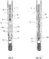
- FIG. 8 illustrates that a seal sleeve 12B (e.g., in the form of hollow or annular cylinders) has been installed, for example, by extending it on the end of an armored cable (wireline or slickline), or by using the intervention tubing (20 in FIG. 2 ) to a position within the areas of the tubing 12 that have been penetrated, e.g., at 12A, except for the lowermost opening 12A1 that is herein illustrated immediately above the packer 14.
- Such sleeves are available from a number of suppliers, and are often referred to as “separation sleeves", "patches”, etc.
- seal sleeve 12B for the present example methods does not need to be pressure tight, and does not need to withstand a large differential pressure; it is only necessary for the seal sleeve 12B to be able to prevent a substantial cross flow of the barrier material (e.g., cement 30 in FIG. 3 ) during the barrier material placement operation.
- barrier material e.g., cement 30 in FIG. 3
- seal sleeves made of metal as well as composite or plastic materials may be used in various examples.
- FIG. 9 illustrates that a dart 32 may be pumped into the wellbore from proximate the wellhead (not shown), where the dart 32 may be followed by a pumping a barrier material 34, as for example cement. Fluids already present in the wellbore are displaced in front of the dart 32 into the annulus 13 through the lowest opening 12A1 in the tubing 12. Fluid in the annulus 13 would typically be returned to a surface tank system coupled by hoses or similar to a wellhead annulus outlet valve (e.g., a casing valve on the wellhead).
- a wellhead annulus outlet valve e.g., a casing valve on the wellhead.
- FIG. 10 illustrates that the dart 32 has landed below the lowest wellbore tubing to annulus opening 12A1, where now the barrier material 34 can be pumped through the same opening 12A1 into the annulus 13.
- FIG. 11 illustrates that a second dart 32A has been pumped in behind the volume of barrier material 34 required to seal off the desired height in the annulus 13, as well as a third dart 32B placed behind a predetermined volume of barrier material 34 (e.g., cement) required to establish a required length barrier within the tubing 12.
- barrier material 34 e.g., cement
- a volume of the barrier material 30 is selected such that a level of the barrier material 34 displaced into the annular space 13 between the wellbore tubing 12 and the wellbore casing or wellbore liner 10 is below a first one of the plurality of openings 12A above the lowermost opening 12A1 when the barrier material 34 is completely displaced from the interior of the wellbore tubing 12.
- the openings 12A, 12AA in the wellbore tubing 12 may be made using an apparatus and method described in International Patent Application Publication No. WO 2015/175025 .
- a possible advantage of using such apparatus and method is that it may be possible to reduce the risk of penetrating the casing or liner as would be the case if other penetration techniques such as explosive shaped charge perforation were used.
Landscapes
- Geology (AREA)
- Life Sciences & Earth Sciences (AREA)
- Engineering & Computer Science (AREA)
- Mining & Mineral Resources (AREA)
- Environmental & Geological Engineering (AREA)
- Fluid Mechanics (AREA)
- Physics & Mathematics (AREA)
- General Life Sciences & Earth Sciences (AREA)
- Geochemistry & Mineralogy (AREA)
- Pipe Accessories (AREA)
- Branch Pipes, Bends, And The Like (AREA)
- Earth Drilling (AREA)
- Pressure Vessels And Lids Thereof (AREA)
Claims (10)
- Verfahren zum Abdichten eines Bohrlochs (2), das die folgenden Schritte umfasst:
Schließen einer Mehrzahl von in Längsrichtung beabstandeter Öffnungen (12A) in dem Bohrlochrohr (12) für einen Fluidstrom aus dem Inneren eines Bohrlochrohres (12), wobei das Bohrlochrohr (12) im Inneren eines Bohrlochgehäuses (10) oder im Inneren einer Bohrlochauskleidung angeordnet ist, wobei die Mehrzahl von in Längsrichtung beabstandeter Öffnungen (12A) in Fluidkommunikation mit einem ringförmigen Raum (13) zwischen dem Bohrlochrohr (12) und dem Bohrlochgehäuse (10) oder der Bohrlochauskleidung steht, wobei das Schließen an allen der Mehrzahl von Öffnungen (12) oberhalb einer niedrigsten der Mehrzahl von Öffnungen (12A) durchgeführt wird, wobei das Schließen des Fluidstromes umfasst:Einsetzen eines Einsatzrohres (20) in das Bohrlochrohr (12), wobei das Bohrlochrohr (12) einen Dichtstopfen (16) in seinem Inneren nahe eines Bodenendes des Bohrlochrohres (12) umfasst;Abdichten eines Längsendes des in dem Bohrlochrohr (12) angeordneten Einsatzrohres (20), wobei das Abdichten ein Herunterlassen einer Dichtkugel oder eines Dichtstifts (18) in das Einsatzrohr (20) umfasst, um die Dichtkugel oder den Dichtstift (18) zu veranlassen, das Längsende des Einsatzrohres (20) an seinem niedrigsten Ende zu schließen;Betätigen einer Dichtung (28), um einen ringförmigen Raum zwischen dem Einsatzrohr (20) und dem Bohrlochrohr (12) an einer Position oberhalb der niedrigsten der Mehrzahl von Öffnungen (12A) und unterhalb einer ersten (12AA) der Mehrzahl von Öffnungen (12A) oberhalb der niedrigsten Öffnung hydraulisch zu schließen; undAnordnen eines Barrierematerials (30) in das Einsatzrohr (20) und Verlagern des Barrierematerials (30) durch das Einsatzrohr (20), durch Anschlüsse (19) in dem Einsatzrohr (20) und platziert unterhalb der Dichtung (28), und dann durch die Öffnungen (12A) in dem Bohrlochrohr (12), die unterhalb der Anschlüsse (19) freiliegend sind, und in den ringförmigen Raum (13) zwischen dem Bohrlochrohr (12) und dem Bohrlochgehäuse (10) oder der Bohrlochauskleidung;Verlagern des Barrierematerials (30) durch die niedrigste Öffnung in den ringförmigen Raum (13) bei einem Niveau unterhalb der ersten (12AA) der Mehrzahl von Öffnungen (12A) oberhalb der niedrigsten Öffnung;Freilegen der ersten Öffnung oberhalb der niedrigsten Öffnung (12AA) für einen Fluidstrom, indem das Einsatzrohr (20) nach oben gezogen wird, wobei das Freilegen ein Beibehalten eines Schließens aller der Mehrzahl von Öffnungen (12A) oberhalb der ersten freiliegenden Öffnung (12AA) umfasst; undAnordnen eines Barrierematerials (30A) in dem Bohrlochrohr (12) und Verlagern des Barrierematerials (30A) durch die erste freigelegte Öffnung (12AA) in den ringförmigen Raum (13). - Verfahren nach Anspruch 1, wobei des Barrierematerial (30) wenigstens eines aus Zement, Harz/Kunststoff, Epoxidharz und Kombinationen davon umfasst.
- Verfahren nach Anspruch 1, das ferner ein Freilegen eines zweiten Endes der Mehrzahl von Öffnungen (12A) oberhalb der ersten freiliegenden Öffnung (12AA) umfasst,
wobei das Freilegen der zweiten Öffnung ein Beibehalten eines Schließens der Mehrzahl von Öffnungen (12A) oberhalb der zweiten freiliegenden Öffnung, ein Anordnen eines Barrierematerials (30B) in dem Bohrlochrohr (12) und ein Verlagern des Barrierematerials (30B) durch die zweite freiliegende Öffnung in dem ringförmigen Raum (13) zu einem Niveau unterhalb einer der Mehrzahl von Öffnungen (12A) oberhalb der zweiten Öffnung umfasst. - Verfahren nach Anspruch 1, wobei das Bohrlochrohr (12) einen Stopfen (16) umfasst, der an einer ausgewählten Position unterhalb der niedrigsten Öffnung angeordnet ist.
- Verfahren nach Anspruch 1, wobei ein Volumen des Barrierematerials (30) derart ausgewählt ist, dass ein Niveau des in den ringförmigen Raum (13) zwischen dem Bohrlochrohr (12) und dem Bohrlochgehäuse (10) oder der Bohrlochauskleidung angeordneten Barrierematerials (30) unter der ersten freiliegenden Öffnung (12AA) liegt.
- Verfahren nach Anspruch 1, wobei die Betätigung der Dichtung (28) ein Pumpen eines Fluides in das Einsatzrohr (20) umfasst, um ein an einer Außenseite des Einsatzrohres (20) angeordnetes Dichtelement auszudehnen.
- Verfahren nach Anspruch 6, das nach dem Ausdehnen der Dichtung und vor dem Anordnen des Barrierematerials (30) ferner ein Ausstoßen des Dichtstifts (18) oder der Dichtkugel umfasst, indem Fluid in das Einsatzrohr (20) gepumpt wird.
- Verfahren nach Anspruch 1, ferner umfassend ein Einsetzen eines Verlagerungsstifts in das Einsatzrohr (20) gefolgt von einem Einsetzen des Barrierematerials (30) in das Einsatzrohr (20) und Pumpen eines Fluides in das Einsatzrohr (20), um den Verlagerungsstift entlang des Einsatzrohres (20) zu bewegen, bis der Verlagerungsstift das Barrierematerial (30) für die niedrigste Öffnung freilegt.
- Verfahren nach Anspruch 1, ferner umfassend:Anheben des Einsatzrohres (20) zu einer Position in dem Bohrlochrohr (12), sodass die Dichtung oberhalb der ersten freiliegenden Öffnung (12AA) angeordnet ist;wiederholtes Abdichten des Längsendes des in dem Bohrlochrohr angeordneten Einsatzrohres (20); undwiederholtes Anordnen eines Barrierematerials (30) in das Einsatzrohr (20) und Verlagern des Barrierematerials (30) durch die erste (12AA) der Mehrzahl von Öffnungen (12A) und in den ringförmigen Raum (13) zwischen dem Bohrlochrohr (12) und dem Bohrlochgehäuse (10) oder der Bohrlochauskleidung.
- Verfahren nach Anspruch 9, wobei das wiederholte Anordnen des Barrierematerials (30) ein derartiges Volumen eines Barrierematerials (30) aufweist, dass ein in dem ringförmigen Raum (13) zwischen dem Bohrlochrohr (12) und dem Bohrlochgehäuse (10) oder der Bohrlochauskleidung angeordnetes Barrierematerial (30) unterhalb einer zweiten der Mehrzahl von Öffnungen (12A) oberhalb der ersten freiliegenden Öffnung (12AA) liegt.
Priority Applications (1)
| Application Number | Priority Date | Filing Date | Title |
|---|---|---|---|
| PL16778473T PL3353373T3 (pl) | 2015-09-22 | 2016-09-16 | Sposoby umieszczania materiału barierowego w odwiercie do pozostawienia na stałe przewodu wydobywczego w rurze okładzinowej w celu zakończenia odwiertu na stałe |
Applications Claiming Priority (2)
| Application Number | Priority Date | Filing Date | Title |
|---|---|---|---|
| US201562221643P | 2015-09-22 | 2015-09-22 | |
| PCT/NO2016/050188 WO2017052378A2 (en) | 2015-09-22 | 2016-09-16 | Methods for placing a barrier material in a wellbore to permanently leave tubing in casing for permanent wellbore abandonment |
Publications (2)
| Publication Number | Publication Date |
|---|---|
| EP3353373A2 EP3353373A2 (de) | 2018-08-01 |
| EP3353373B1 true EP3353373B1 (de) | 2020-04-01 |
Family
ID=57113651
Family Applications (1)
| Application Number | Title | Priority Date | Filing Date |
|---|---|---|---|
| EP16778473.5A Active EP3353373B1 (de) | 2015-09-22 | 2016-09-16 | Verfahren zur platzierung eines sperrmaterials in einem bohrloch zum dauerhaften belassen eines rohrs in einer hülle für permanente bohlochauflassung |
Country Status (6)
| Country | Link |
|---|---|
| US (1) | US10107067B2 (de) |
| EP (1) | EP3353373B1 (de) |
| CA (1) | CA2997006C (de) |
| DK (1) | DK3353373T3 (de) |
| PL (1) | PL3353373T3 (de) |
| WO (1) | WO2017052378A2 (de) |
Families Citing this family (4)
| Publication number | Priority date | Publication date | Assignee | Title |
|---|---|---|---|---|
| US10408015B2 (en) * | 2017-07-24 | 2019-09-10 | Baker Hughes, A Ge Company, Llc | Combination bottom up and top down cementing with reduced time to set liner hanger/packer after top down cementing |
| GB2577935B (en) * | 2018-10-12 | 2020-12-16 | Equinor Energy As | Permanent plug and abandonment plug established and verified with overdisplaced cement in A-annulus |
| US12163400B2 (en) | 2021-03-29 | 2024-12-10 | Conocophillips Company | Plug and abandon operation in a hydrocarbon well by cementing the annulus through apertures in the casing |
| US12448559B1 (en) * | 2024-06-06 | 2025-10-21 | Halliburton Energy Services, Inc. | Puddle job with delayed setting of resin via a polymerization reaction with an activator |
Family Cites Families (14)
| Publication number | Priority date | Publication date | Assignee | Title |
|---|---|---|---|---|
| USRE19570E (en) * | 1935-05-14 | Method and apparatus for cementing | ||
| US2249511A (en) * | 1936-09-01 | 1941-07-15 | Edward F Westall | Apparatus and method for cementing wells |
| US2368419A (en) * | 1940-03-18 | 1945-01-30 | Baker Oil Tools Inc | Well cementing apparatus |
| US3768562A (en) * | 1972-05-25 | 1973-10-30 | Halliburton Co | Full opening multiple stage cementing tool and methods of use |
| US4105069A (en) | 1977-06-09 | 1978-08-08 | Halliburton Company | Gravel pack liner assembly and selective opening sleeve positioner assembly for use therewith |
| US5884702A (en) * | 1996-03-01 | 1999-03-23 | Smith International, Inc. | Liner assembly and method |
| US5960881A (en) * | 1997-04-22 | 1999-10-05 | Jerry P. Allamon | Downhole surge pressure reduction system and method of use |
| US6085838A (en) * | 1997-05-27 | 2000-07-11 | Schlumberger Technology Corporation | Method and apparatus for cementing a well |
| US6899183B2 (en) * | 2001-05-18 | 2005-05-31 | Smith International, Inc. | Casing attachment method and apparatus |
| US20090071644A1 (en) * | 2002-08-21 | 2009-03-19 | Packers Plus Energy Services Inc. | Apparatus and method for wellbore isolation |
| US8720561B2 (en) | 2011-04-12 | 2014-05-13 | Saudi Arabian Oil Company | Sliding stage cementing tool and method |
| US9488024B2 (en) | 2012-04-16 | 2016-11-08 | Wild Well Control, Inc. | Annulus cementing tool for subsea abandonment operation |
| WO2014137314A1 (en) * | 2013-03-04 | 2014-09-12 | Halliburton Energy Services, Inc. | Abandonment and containment system for gas wells |
| US9631468B2 (en) | 2013-09-03 | 2017-04-25 | Schlumberger Technology Corporation | Well treatment |
-
2016
- 2016-09-12 US US15/262,109 patent/US10107067B2/en active Active
- 2016-09-16 EP EP16778473.5A patent/EP3353373B1/de active Active
- 2016-09-16 CA CA2997006A patent/CA2997006C/en active Active
- 2016-09-16 DK DK16778473.5T patent/DK3353373T3/da active
- 2016-09-16 WO PCT/NO2016/050188 patent/WO2017052378A2/en not_active Ceased
- 2016-09-16 PL PL16778473T patent/PL3353373T3/pl unknown
Non-Patent Citations (1)
| Title |
|---|
| None * |
Also Published As
| Publication number | Publication date |
|---|---|
| PL3353373T3 (pl) | 2021-04-06 |
| CA2997006A1 (en) | 2017-03-30 |
| US20170081943A1 (en) | 2017-03-23 |
| WO2017052378A3 (en) | 2017-08-31 |
| US10107067B2 (en) | 2018-10-23 |
| WO2017052378A9 (en) | 2017-10-12 |
| CA2997006C (en) | 2020-09-01 |
| WO2017052378A2 (en) | 2017-03-30 |
| DK3353373T3 (da) | 2020-06-29 |
| EP3353373A2 (de) | 2018-08-01 |
Similar Documents
| Publication | Publication Date | Title |
|---|---|---|
| US10519753B2 (en) | Apparatus and method for running casing in a wellbore | |
| US10612342B2 (en) | Plugging tool, and method of plugging a well | |
| US8127846B2 (en) | Wiper plug perforating system | |
| US8794331B2 (en) | Tools and methods for use in completion of a wellbore | |
| CA2383683C (en) | Well completion method and apparatus | |
| CN101086198B (zh) | 在地层中制出井孔的方法 | |
| EP3415711A1 (de) | Bohrloch-patch-einstellwerkzeug | |
| EA025346B1 (ru) | Способ комбинированной очистки и тампонирования скважины | |
| EP0604526A1 (de) | Im bohrloch aktiviertes verfahren und vorrichtung zum zentralisiern von rohren in bohrlöchern | |
| CN101395337A (zh) | 用于选择性处理射孔套管的方法和装置 | |
| US8807210B2 (en) | Downhole tool with pumpable section | |
| WO2012061202A2 (en) | Method and apparatus for creating an annular barrier in a subterranean wellbore | |
| US9587456B2 (en) | Packer setting method using disintegrating plug | |
| US20200131880A1 (en) | Downhole packer tool engaging and opening port sleeve utilizing hydraulic force of fracturing fluid | |
| US10947815B2 (en) | Tool assembly with collet and shiftable valve and process for directing fluid flow in a wellbore | |
| CA2997006C (en) | Methods for placing a barrier material in a wellbore to permanently leave tubing in casing for permanent wellbore abandonment | |
| US9022114B2 (en) | Cement shoe and method of cementing well with open hole below the shoe | |
| GB2579349A (en) | A-annulus cementing without pumping cement | |
| US9951580B2 (en) | Well barrier method and apparatus | |
| US10036237B2 (en) | Mechanically-set devices placed on outside of tubulars in wellbores | |
| EP3216975A1 (de) | Bohrlochsystem | |
| NO20180239A1 (en) | A plugging tool, and method of plugging a well |
Legal Events
| Date | Code | Title | Description |
|---|---|---|---|
| STAA | Information on the status of an ep patent application or granted ep patent |
Free format text: STATUS: THE INTERNATIONAL PUBLICATION HAS BEEN MADE |
|
| PUAI | Public reference made under article 153(3) epc to a published international application that has entered the european phase |
Free format text: ORIGINAL CODE: 0009012 |
|
| STAA | Information on the status of an ep patent application or granted ep patent |
Free format text: STATUS: REQUEST FOR EXAMINATION WAS MADE |
|
| 17P | Request for examination filed |
Effective date: 20180423 |
|
| AK | Designated contracting states |
Kind code of ref document: A2 Designated state(s): AL AT BE BG CH CY CZ DE DK EE ES FI FR GB GR HR HU IE IS IT LI LT LU LV MC MK MT NL NO PL PT RO RS SE SI SK SM TR |
|
| AX | Request for extension of the european patent |
Extension state: BA ME |
|
| DAV | Request for validation of the european patent (deleted) | ||
| DAX | Request for extension of the european patent (deleted) | ||
| STAA | Information on the status of an ep patent application or granted ep patent |
Free format text: STATUS: EXAMINATION IS IN PROGRESS |
|
| 17Q | First examination report despatched |
Effective date: 20190409 |
|
| GRAP | Despatch of communication of intention to grant a patent |
Free format text: ORIGINAL CODE: EPIDOSNIGR1 |
|
| STAA | Information on the status of an ep patent application or granted ep patent |
Free format text: STATUS: GRANT OF PATENT IS INTENDED |
|
| INTG | Intention to grant announced |
Effective date: 20191119 |
|
| GRAS | Grant fee paid |
Free format text: ORIGINAL CODE: EPIDOSNIGR3 |
|
| GRAA | (expected) grant |
Free format text: ORIGINAL CODE: 0009210 |
|
| STAA | Information on the status of an ep patent application or granted ep patent |
Free format text: STATUS: THE PATENT HAS BEEN GRANTED |
|
| AK | Designated contracting states |
Kind code of ref document: B1 Designated state(s): AL AT BE BG CH CY CZ DE DK EE ES FI FR GB GR HR HU IE IS IT LI LT LU LV MC MK MT NL NO PL PT RO RS SE SI SK SM TR |
|
| REG | Reference to a national code |
Ref country code: GB Ref legal event code: FG4D |
|
| REG | Reference to a national code |
Ref country code: CH Ref legal event code: EP Ref country code: AT Ref legal event code: REF Ref document number: 1251553 Country of ref document: AT Kind code of ref document: T Effective date: 20200415 |
|
| REG | Reference to a national code |
Ref country code: DE Ref legal event code: R096 Ref document number: 602016033134 Country of ref document: DE |
|
| REG | Reference to a national code |
Ref country code: IE Ref legal event code: FG4D |
|
| REG | Reference to a national code |
Ref country code: NO Ref legal event code: T2 Effective date: 20200401 Ref country code: DK Ref legal event code: T3 Effective date: 20200625 |
|
| REG | Reference to a national code |
Ref country code: NL Ref legal event code: FP |
|
| PG25 | Lapsed in a contracting state [announced via postgrant information from national office to epo] |
Ref country code: BG Free format text: LAPSE BECAUSE OF FAILURE TO SUBMIT A TRANSLATION OF THE DESCRIPTION OR TO PAY THE FEE WITHIN THE PRESCRIBED TIME-LIMIT Effective date: 20200701 |
|
| REG | Reference to a national code |
Ref country code: GR Ref legal event code: EP Ref document number: 20200401792 Country of ref document: GR Effective date: 20200916 |
|
| REG | Reference to a national code |
Ref country code: LT Ref legal event code: MG4D |
|
| PG25 | Lapsed in a contracting state [announced via postgrant information from national office to epo] |
Ref country code: FI Free format text: LAPSE BECAUSE OF FAILURE TO SUBMIT A TRANSLATION OF THE DESCRIPTION OR TO PAY THE FEE WITHIN THE PRESCRIBED TIME-LIMIT Effective date: 20200401 Ref country code: PT Free format text: LAPSE BECAUSE OF FAILURE TO SUBMIT A TRANSLATION OF THE DESCRIPTION OR TO PAY THE FEE WITHIN THE PRESCRIBED TIME-LIMIT Effective date: 20200817 Ref country code: IS Free format text: LAPSE BECAUSE OF FAILURE TO SUBMIT A TRANSLATION OF THE DESCRIPTION OR TO PAY THE FEE WITHIN THE PRESCRIBED TIME-LIMIT Effective date: 20200801 Ref country code: SE Free format text: LAPSE BECAUSE OF FAILURE TO SUBMIT A TRANSLATION OF THE DESCRIPTION OR TO PAY THE FEE WITHIN THE PRESCRIBED TIME-LIMIT Effective date: 20200401 Ref country code: CZ Free format text: LAPSE BECAUSE OF FAILURE TO SUBMIT A TRANSLATION OF THE DESCRIPTION OR TO PAY THE FEE WITHIN THE PRESCRIBED TIME-LIMIT Effective date: 20200401 Ref country code: LT Free format text: LAPSE BECAUSE OF FAILURE TO SUBMIT A TRANSLATION OF THE DESCRIPTION OR TO PAY THE FEE WITHIN THE PRESCRIBED TIME-LIMIT Effective date: 20200401 |
|
| REG | Reference to a national code |
Ref country code: AT Ref legal event code: MK05 Ref document number: 1251553 Country of ref document: AT Kind code of ref document: T Effective date: 20200401 |
|
| PG25 | Lapsed in a contracting state [announced via postgrant information from national office to epo] |
Ref country code: HR Free format text: LAPSE BECAUSE OF FAILURE TO SUBMIT A TRANSLATION OF THE DESCRIPTION OR TO PAY THE FEE WITHIN THE PRESCRIBED TIME-LIMIT Effective date: 20200401 Ref country code: RS Free format text: LAPSE BECAUSE OF FAILURE TO SUBMIT A TRANSLATION OF THE DESCRIPTION OR TO PAY THE FEE WITHIN THE PRESCRIBED TIME-LIMIT Effective date: 20200401 Ref country code: LV Free format text: LAPSE BECAUSE OF FAILURE TO SUBMIT A TRANSLATION OF THE DESCRIPTION OR TO PAY THE FEE WITHIN THE PRESCRIBED TIME-LIMIT Effective date: 20200401 |
|
| PG25 | Lapsed in a contracting state [announced via postgrant information from national office to epo] |
Ref country code: AL Free format text: LAPSE BECAUSE OF FAILURE TO SUBMIT A TRANSLATION OF THE DESCRIPTION OR TO PAY THE FEE WITHIN THE PRESCRIBED TIME-LIMIT Effective date: 20200401 |
|
| REG | Reference to a national code |
Ref country code: DE Ref legal event code: R097 Ref document number: 602016033134 Country of ref document: DE |
|
| PG25 | Lapsed in a contracting state [announced via postgrant information from national office to epo] |
Ref country code: ES Free format text: LAPSE BECAUSE OF FAILURE TO SUBMIT A TRANSLATION OF THE DESCRIPTION OR TO PAY THE FEE WITHIN THE PRESCRIBED TIME-LIMIT Effective date: 20200401 Ref country code: AT Free format text: LAPSE BECAUSE OF FAILURE TO SUBMIT A TRANSLATION OF THE DESCRIPTION OR TO PAY THE FEE WITHIN THE PRESCRIBED TIME-LIMIT Effective date: 20200401 Ref country code: SM Free format text: LAPSE BECAUSE OF FAILURE TO SUBMIT A TRANSLATION OF THE DESCRIPTION OR TO PAY THE FEE WITHIN THE PRESCRIBED TIME-LIMIT Effective date: 20200401 Ref country code: IT Free format text: LAPSE BECAUSE OF FAILURE TO SUBMIT A TRANSLATION OF THE DESCRIPTION OR TO PAY THE FEE WITHIN THE PRESCRIBED TIME-LIMIT Effective date: 20200401 Ref country code: EE Free format text: LAPSE BECAUSE OF FAILURE TO SUBMIT A TRANSLATION OF THE DESCRIPTION OR TO PAY THE FEE WITHIN THE PRESCRIBED TIME-LIMIT Effective date: 20200401 Ref country code: RO Free format text: LAPSE BECAUSE OF FAILURE TO SUBMIT A TRANSLATION OF THE DESCRIPTION OR TO PAY THE FEE WITHIN THE PRESCRIBED TIME-LIMIT Effective date: 20200401 |
|
| PLBE | No opposition filed within time limit |
Free format text: ORIGINAL CODE: 0009261 |
|
| STAA | Information on the status of an ep patent application or granted ep patent |
Free format text: STATUS: NO OPPOSITION FILED WITHIN TIME LIMIT |
|
| PG25 | Lapsed in a contracting state [announced via postgrant information from national office to epo] |
Ref country code: SK Free format text: LAPSE BECAUSE OF FAILURE TO SUBMIT A TRANSLATION OF THE DESCRIPTION OR TO PAY THE FEE WITHIN THE PRESCRIBED TIME-LIMIT Effective date: 20200401 |
|
| 26N | No opposition filed |
Effective date: 20210112 |
|
| REG | Reference to a national code |
Ref country code: CH Ref legal event code: PL |
|
| PG25 | Lapsed in a contracting state [announced via postgrant information from national office to epo] |
Ref country code: SI Free format text: LAPSE BECAUSE OF FAILURE TO SUBMIT A TRANSLATION OF THE DESCRIPTION OR TO PAY THE FEE WITHIN THE PRESCRIBED TIME-LIMIT Effective date: 20200401 |
|
| REG | Reference to a national code |
Ref country code: BE Ref legal event code: MM Effective date: 20200930 |
|
| PG25 | Lapsed in a contracting state [announced via postgrant information from national office to epo] |
Ref country code: LU Free format text: LAPSE BECAUSE OF NON-PAYMENT OF DUE FEES Effective date: 20200916 |
|
| PG25 | Lapsed in a contracting state [announced via postgrant information from national office to epo] |
Ref country code: FR Free format text: LAPSE BECAUSE OF NON-PAYMENT OF DUE FEES Effective date: 20200930 |
|
| PG25 | Lapsed in a contracting state [announced via postgrant information from national office to epo] |
Ref country code: IE Free format text: LAPSE BECAUSE OF NON-PAYMENT OF DUE FEES Effective date: 20200916 Ref country code: LI Free format text: LAPSE BECAUSE OF NON-PAYMENT OF DUE FEES Effective date: 20200930 Ref country code: CH Free format text: LAPSE BECAUSE OF NON-PAYMENT OF DUE FEES Effective date: 20200930 Ref country code: BE Free format text: LAPSE BECAUSE OF NON-PAYMENT OF DUE FEES Effective date: 20200930 |
|
| PG25 | Lapsed in a contracting state [announced via postgrant information from national office to epo] |
Ref country code: TR Free format text: LAPSE BECAUSE OF FAILURE TO SUBMIT A TRANSLATION OF THE DESCRIPTION OR TO PAY THE FEE WITHIN THE PRESCRIBED TIME-LIMIT Effective date: 20200401 Ref country code: MT Free format text: LAPSE BECAUSE OF FAILURE TO SUBMIT A TRANSLATION OF THE DESCRIPTION OR TO PAY THE FEE WITHIN THE PRESCRIBED TIME-LIMIT Effective date: 20200401 Ref country code: CY Free format text: LAPSE BECAUSE OF FAILURE TO SUBMIT A TRANSLATION OF THE DESCRIPTION OR TO PAY THE FEE WITHIN THE PRESCRIBED TIME-LIMIT Effective date: 20200401 |
|
| PG25 | Lapsed in a contracting state [announced via postgrant information from national office to epo] |
Ref country code: MK Free format text: LAPSE BECAUSE OF FAILURE TO SUBMIT A TRANSLATION OF THE DESCRIPTION OR TO PAY THE FEE WITHIN THE PRESCRIBED TIME-LIMIT Effective date: 20200401 Ref country code: MC Free format text: LAPSE BECAUSE OF FAILURE TO SUBMIT A TRANSLATION OF THE DESCRIPTION OR TO PAY THE FEE WITHIN THE PRESCRIBED TIME-LIMIT Effective date: 20200401 |
|
| P01 | Opt-out of the competence of the unified patent court (upc) registered |
Effective date: 20230525 |
|
| PGFP | Annual fee paid to national office [announced via postgrant information from national office to epo] |
Ref country code: DK Payment date: 20250919 Year of fee payment: 10 Ref country code: DE Payment date: 20250923 Year of fee payment: 10 |
|
| PGFP | Annual fee paid to national office [announced via postgrant information from national office to epo] |
Ref country code: GR Payment date: 20250929 Year of fee payment: 10 Ref country code: NO Payment date: 20250919 Year of fee payment: 10 |
|
| PGFP | Annual fee paid to national office [announced via postgrant information from national office to epo] |
Ref country code: PL Payment date: 20250924 Year of fee payment: 10 Ref country code: NL Payment date: 20250919 Year of fee payment: 10 |
|
| PGFP | Annual fee paid to national office [announced via postgrant information from national office to epo] |
Ref country code: GB Payment date: 20250919 Year of fee payment: 10 |