EP3353509B1 - Flüssigkeitsstandanzeiger - Google Patents
Flüssigkeitsstandanzeiger Download PDFInfo
- Publication number
- EP3353509B1 EP3353509B1 EP16849759.2A EP16849759A EP3353509B1 EP 3353509 B1 EP3353509 B1 EP 3353509B1 EP 16849759 A EP16849759 A EP 16849759A EP 3353509 B1 EP3353509 B1 EP 3353509B1
- Authority
- EP
- European Patent Office
- Prior art keywords
- float
- pushrod
- cage
- water level
- upper housing
- Prior art date
- Legal status (The legal status is an assumption and is not a legal conclusion. Google has not performed a legal analysis and makes no representation as to the accuracy of the status listed.)
- Active
Links
Images


Classifications
-
- A—HUMAN NECESSITIES
- A01—AGRICULTURE; FORESTRY; ANIMAL HUSBANDRY; HUNTING; TRAPPING; FISHING
- A01G—HORTICULTURE; CULTIVATION OF VEGETABLES, FLOWERS, RICE, FRUIT, VINES, HOPS OR SEAWEED; FORESTRY; WATERING
- A01G27/00—Self-acting watering devices, e.g. for flower-pots
- A01G27/008—Component parts, e.g. dispensing fittings, level indicators
-
- G—PHYSICS
- G01—MEASURING; TESTING
- G01F—MEASURING VOLUME, VOLUME FLOW, MASS FLOW OR LIQUID LEVEL; METERING BY VOLUME
- G01F23/00—Indicating or measuring liquid level or level of fluent solid material, e.g. indicating in terms of volume or indicating by means of an alarm
- G01F23/30—Indicating or measuring liquid level or level of fluent solid material, e.g. indicating in terms of volume or indicating by means of an alarm by floats
- G01F23/56—Indicating or measuring liquid level or level of fluent solid material, e.g. indicating in terms of volume or indicating by means of an alarm by floats using elements rigidly fixed to, and rectilinearly moving with, the floats as transmission elements
- G01F23/58—Indicating or measuring liquid level or level of fluent solid material, e.g. indicating in terms of volume or indicating by means of an alarm by floats using elements rigidly fixed to, and rectilinearly moving with, the floats as transmission elements using mechanically actuated indicating means
-
- G—PHYSICS
- G01—MEASURING; TESTING
- G01F—MEASURING VOLUME, VOLUME FLOW, MASS FLOW OR LIQUID LEVEL; METERING BY VOLUME
- G01F23/00—Indicating or measuring liquid level or level of fluent solid material, e.g. indicating in terms of volume or indicating by means of an alarm
- G01F23/30—Indicating or measuring liquid level or level of fluent solid material, e.g. indicating in terms of volume or indicating by means of an alarm by floats
- G01F23/64—Indicating or measuring liquid level or level of fluent solid material, e.g. indicating in terms of volume or indicating by means of an alarm by floats of the free float type without mechanical transmission elements
- G01F23/66—Indicating or measuring liquid level or level of fluent solid material, e.g. indicating in terms of volume or indicating by means of an alarm by floats of the free float type without mechanical transmission elements using mechanically actuated indicating means
Definitions
- the present disclosure generally relates to the field of water level indicators for liquid containers such as self-watering planters.
- Water level indicators may be used in a variety of fields for various purposes, including self-watering planters, and other types of liquid storage containers.
- a water level indicator may refer to any device that measures the amount of any liquid in any type of liquid container.
- prior art water level indicators based on a floating push rod may indicate the amount of liquid in the container based on how high the push rod extends above the surface of the water storage container within an observation cap.
- Patent documents US 1 185 985 A and DE 33 23 046 C1 relate to known liquid level indicators or known water level indicators in the prior art.
- water level indicators may indicate the liquid level within a liquid container through the use of a window in the side of the liquid container.
- water level indicators may only allow a user to observe the indicated water level by examining the window, which may not be easily read from all levels of the device. For example a planter with such a device put against a wall, or amongst other similar planters may require a user to crouch to view the water level indicator window, or turn the planter to access a view of an obscured window.
- a water level indicator comprising: a shell having a top end and a bottom end; a plurality of pushrods disposed within the shell, wherein each of the pushrods has a first end and a second end defining a length that is different from the lengths of the other pushrods in the plurality of pushrods; a plurality of floats, wherein each float comprises a locking hole, which receives and secures a second end of one of the plurality of pushrods, and wherein at least one of the plurality of floats comprises at least one through hole which allows the pushrod(s) that are not secured to the float to pass through the float; and an upper housing, comprising one or more cavities, wherein a plurality of indicator flag caps are disposed within the one or more cavities in the upper housing, wherein the first end of each pushrod in the plurality of pushrods is connected to a different indicator flag cap, wherein the shell substantially encloses the upper housing, the plurality of indicator flag
- a self-watering planter may include an internal wall and floor defining a plant cavity, an external wall surrounding a water reservoir, and an inlet capable of allowing water to enter the water reservoir.
- the self-watering planter may further have a water level indicator according to the invention.
- a water level indicator has an upper housing, comprising a cavity, wherein a plurality of indicator flag caps therein.
- a plurality of pushrods each have a first end and a second end to define a length that is different from the lengths of the other pushrods in the plurality of pushrods.
- the first end of each pushrod in the plurality of pushrods connects to a different indicator flag cap.
- the water level indicator includes a plurality of floats such that each float has a locking hole, which receives and secures a second end of one of the plurality of pushrods.
- a first float of the plurality of float cages has its locking hole secure the second end of a first pushrod of the plurality of pushrods, and further has at least one through hole which allows a second pushrod of the plurality of pushrods, to pass through the first float.
- the water level indicator has a shell.
- each of plurality of float may further include a float cage such that the locking hole in each of the floats is disposed within the float cage of each respective float.
- the float cages of the water level indicators have a spacer that separate the sides of the float cages from the shell.
- the upper housing further comprises locking wings.
- the water level indicator may also have a top cap having a window, a rim, and an outer wall, where the outer wall surrounds the upper housing. The outer wall may further have cut outs that accommodate the locking wings of the upper housing.
- the cavity may comprise a plurality of cavities in the upper housing, including a first cavity, a second cavity and a third cavity.
- the water level indicator may also have the at least one through hole in the first float include a first through hole and a second through hole.
- a first through hole of the at least one through holes in the first float, and the locking hole in the first float may each have extension walls, such that the extension walls of the first through hole engage the first through hole in the first float, and the extension walls of the locking hole engage the second through hole in the first float.
- the extension walls of the locking hole of the first float have a floor.
- a self-watering planter may include an internal wall and floor defining a plant cavity, an external wall surrounding a water reservoir, and an inlet capable of allowing water to enter the water reservoir.
- the self-watering planter may further have a water level indicator which may have an upper housing, comprising a cavity, wherein a plurality of indicator flag caps may be disposed.
- a plurality of pushrods may each have a first end and a second end to define a length that is different from the lengths of the other pushrods in the plurality of pushrods. The first end of each pushrod in the plurality of pushrods may connect to a different indicator flag cap.
- the water level indicator may include a plurality of floats such that each float may have a locking hole, which receives and secures a second end of one of the plurality of pushrods.
- a first float of the plurality of floats may have its locking hole secure the second end of a first pushrod of the plurality of pushrods, and may further have at least one through hole which allows a second pushrod of the plurality of pushrods, to pass through the first float.
- each of the plurality of floats may further include a float cage such that the locking hole in each of the floats is disposed within the float cage of each respective float.
- the float cages of the water level indicators have a spacer that separate the sides of the float cages from the shell.
- the upper housing further comprises locking wings.
- the water level indicator may also have a top cap having a window, a rim, and an outer wall, where the outer wall surrounds the upper housing. The outer wall may further have cut outs that accommodate the locking wings of the upper housing.
- the cavity may comprise a plurality of cavities, including a first cavity, a second cavity and a third cavity.
- the water level indicator may also have the at least one through hole in the first float include a first through hole and a second through hole.
- a first through hole of the at least one through holes in the first float, and the locking hole in the first float may each have extension walls, such that the extension walls of the first through hole engage the first through hole in the first float, and the extension walls of the locking hole engage the second through hole in the first float.
- the extension walls of the locking hole of the first float have a floor.
- a water level indicator includes an upper housing, having at least three cavities, including a first cavity, a second cavity and a third cavity.
- An indicator flag cap is disposed within each cavity in the upper housing.
- the length of the first pushrod may be shorter than the length of the second pushrod, and the length of the second pushrod may be shorter than the length of the first pushrod.
- each pushrod in the plurality of pushrods is connected to a different indicator flag cap, such that the first end of the first pushrod is connected to the indicator flag in the first cavity of the upper housing, the first end of the second pushrod is connected to the indicator flag in the second cavity of the upper housing, and the first end of the third pushrod is connected to the indicator flag in the third cavity of the upper housing.
- a plurality of floats may include a first float, a second float and a third float.
- a plurality of float cages may include a first float cage, a second float cage and a third float cage, wherein each float in the plurality of floats is disposed within one of the plurality float cages, such that the first float is disposed in the first float cage, the second float is disposed in the second float cage, and the third float is disposed in the third float cage.
- Each float cage may have a locking hole, which receives and secures a second end of one of the plurality of pushrods such that the first float cage receives and secures the first pushrod in its locking hole, the second float cage receives and secures the second pushrod in its locking hole, and the third float cage receives and secures the third pushrod in its locking hole.
- the first float cage and a first float each may have at least two through holes which allows the second pushrod and third pushrod of the plurality of pushrods, to pass through the first float cage and the first float.
- the second float cage and second float may have at least one through hole, which allows the third pushrod to pass through the second float cage and the second float.
- a water fluid level indicator includes an upper housing having a cavity, and a plurality of indicator flag caps, including a first indicator flag cap and a second indicator flag cap. Each indicator flag cap may be disposed and movable within the cavity in the upper housing.
- the water fluid level indicator also includes a plurality of pushrods, including a first push rod and a second pushrod, where each pushrod substantially elongate and having an upper rod end and a lower rod end. The distance between the upper and lower rod ends defining the length of the pushrod, such that the first push rod may have a different length than the second push rod.
- the second pushrod has a first end and a second end defining a length that is different from the lengths of any of the other pushrods in the plurality of pushrods.
- the first flag cap may be connected with the first push rod at or proximate to its upper end and the second flag cap connected with the second push rod at or proximate to its upper end.
- the first end of each pushrod in the plurality of pushrods is connected to a different indicator flag cap in the plurality of flag caps.
- the water fluid level indicator may also include a plurality of float cages, including a first float cage and a second float cage, wherein each float cage comprises including a locking hole, and the first float cage including a through hole.
- the first pushrod may be secured within the locking hole of the first float cage, and the second pushrod may extend through the through hole of the first float cage and may be secured within the locking hole of the second float cage.
- the first float cage of the plurality of float cages may include at least one through hole which allows the second pushrod of the plurality of pushrods, to pass through the first float cage.
- the water fluid level further includes a shell substantially enclosing the upper housing, flag caps, pushrods, and float cages.
- the water fluid level indicator may further include the float cages that include a spacer that separate the sides of the float cage from the shell.
- each of the plurality of float cages of the water fluid level indicator may further include a float disposed within the float cage.
- the water fluid level indicator may further include an upper housing having locking wings projecting from an outer surface of the upper housing.
- the water fluid level indicator may further include a top cap having a window, a rim, and an outer wall, wherein the outer wall surrounds the outer surface of the upper housing, and comprises cut outs that accommodate the locking wings of the upper housing.
- the water fluid level indicator may further include a cavity having a plurality of cavities, including a first cavity correspondingly, a second cavity, the first indictor flag cap disposed and movable within the first cavity and the second indicator flag cap disposed and movable within the second cavity and a third cavity.
- the water fluid level indicator may further include a plurality of indicator flag caps having a third indicator flag cap, wherein the plurality of pushrods further includes a third pushrod.
- the third pushrod may have a different length than the first pushrod and the second pushrod.
- the third flag cap may be connected to the third pushrod at or proximate to its upper end.
- the plurality of float cages may further include a third float cage, such that the first float cage includes an additional through hole, and the second float cage includes a through hole, and wherein the third push rod extends through the additional through hole of the first float cage as well as the through hole of the second float cage, and is secured within the locking hole of the third float cage.
- FIG. 1 illustrates a perspective view of a self-watering 10 planter in accordance with an embodiment.
- a self-watering planter 10 is depicted as an example of a liquid container in accordance with an embodiment of the disclosed concepts.
- the water level indicator 1 disclosed herein can be implemented in any type of liquid container.
- water or “liquid” may refer to water, an aqueous solution, or any other liquid whose level is to be measured by the water level indicator 1.
- the self-watering planter 10 shown in Figure 1 may have a plant cavity or compartment 11 defined at least in parts by internal wall 12, and floor 13.
- An inlet 14 allows a user to deposit water or another liquid into a liquid reservoir 16 that, in the illustrated embodiment, is concentrically disposed within a portion of the outer wall 15 of the self-watering planter.
- the self-watering planter 10 may also have a water level indicator 1 as will be discussed in greater detail below.
- the plant cavity 11 may be cylindrical, rectangular, or may have any suitable shape desired by a person of ordinary skill in the art implementing such an embodiment in accordance with the disclosed concepts. Accordingly, the internal wall 12 and floor 13 of the self-watering planter10 may have a single section, or may comprise multiple wall or floor sections. The plant cavity 11 need not have a floor, and may be defined by the internal wall 12 alone. At least a portion of the plant cavity 11 may extend into the liquid reservoir 16, may have a porous section which allows water to enter the plant cavity and provide water to a plant located therein.
- the plant cavity 11 may be filled with gravel, dirt, and a plant, and any other materials, or creatures (such as worms) desired by the user of the self-watering planter.
- the inlet 11 allows water to an interior space within the outer wall 15 of the self-watering planter 10 and to enter the liquid reservoir 16.
- a cap (not shown in Figure 1 , but further described herein) may be provided to cover the inlet 14 when the inlet is not being used to refill the liquid reservoir 16.
- the inlet 14 may be separate from the opening which receives the water level indicator 1, as shown in Figure 1 .
- the water level indicator may 1 reside within inlet 14.
- the liquid reservoir 16 may have any suitable shape desired by a person implementing the disclosed concepts.
- the self-watering planter may have any other features known in the art, including outlets, water overflow outlets, ribs or other internal structure to secure the water level indicator 1 or otherwise hold it in place.
- Such internal structure may include recesses (not shown) to receive and secure the wings 25 of the upper housing 2 of the water level indicator 1.
- Such recesses may be similar in shape and functionality to the cutouts 84 and locking slot 85 shown in the top cap 8 in Figure 36 .
- the water level indicator 1 may be used in connection with any liquid container, and the self-watering planter embodiment 10, is to be considered exemplary and not limiting.
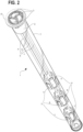
- FIGS 2-8 illustrate a water level indicator in accordance with an embodiment of the disclosure.
- a top cap 8 and an upper housing 2 houses a plurality of indicator flag caps 3, including the illustrated embodiment of three flag caps 3a, 3b, 3c.
- Each indicator flag cap 3, 3a, 3b, 3c is connected to a pushrod 6, 6a, 6b, 6c.
- the plurality of pushrods 6 extend beyond the upper housing, into a shell 7.
- the shell may also house a plurality of float cages 4, 4a, 4b, 4c, each of which may contain floats 5, 5a, 5b, 5c.
- floats 5 and float cages 4 may refer to the same object or to separate objects.
- a "float cage” 4 that floats may simultaneoustly be a float 5, and a float 5 that secures a pushrod may simultaneously be, or include, a float cage 4.
- a float 5 and a float cage 4 may be a unitary structure, may be separate structures, or each float 5 and float cage 4 respectively may be comprised of multiple structures.
- a float 5 may be said to comprise a float cage 4, or a float cage 4 may be said to comprise a float 5, or they may be described separately for convenience, all within the scope of the disclosed concepts.
- the description set forth here is exemplary and not intended to be limiting.
- the float cages 4a, 4b, 4c may receive and secure pushrods 4a, 4b, 4c, or allow them to pass through the float cage 4 and float 5 structures.
- float cage 4a receives and secures pushrod 6a, but allows pushrods 6b and 6c to pass through float cage 4a and float 5a.
- a tunnel, aperture, slot, or other structural opening may be provided such that a passing through push rod may extend beyond a far edge of its float cage 4.
- float cage 4b receives and secures pushrod 6b, but allows pushrod 6c to pass through float cage 4b and float 5b.
- float cage 4c receives and secures pushrod 5c.
- the water level indicator 1 may also include a bottom cap 9 such that bottom cap 9 and top cap 3 may be provided at opposed, longitudinal ends of shell 6.
- the pushrods slidably engage the upper housing 2, such that the indicator flag caps 3 may rise and fall within the upper housing 2.
- the float cages 4, 4a, 4b, 4c may secure a pushrod 6, 6a, 6b, 6c, and may allow the other unsecured pushrods 6, 6b, 6c, to slidably pass through the float cage 4, 4a, 4b.
- Shell 6 may be in fluid communication with liquid reservoir 16 such that water may enter shell 6 as liquid reservoir 16 is correspondingly filled. In this manner, the water level in the liquid container 16 forces the floats and float cages up, beginning with the lowest float cage 4c and float 5c.
- the float cage 4c and float 5c push the secured pushrod 6c upwards, which in turn pushes the connected indicator flag cap 3c upwards towards the top of the upper housing 2.
- the other float cages 4a, 4b and their floats 5a, 5b push their respective pushrods 6a, 6b, and their respective indicator flag caps 3a, 3b upwards. Accordingly, a user of the water level indictor 1 can see at a glance water level within the liquid reservoir 16 based on the number of water indicator flags that are visible at the top of the upper housing.
- the liquid reservoir 16 is at or nearly at 100% capacity. If only two indicator flag caps 3b and 3c are in a raised position at the top of the upper housing 2, the liquid reservoir 16 may be at least at two-thirds capacity. If only one indicator flag caps 3c is in a raised position at the top of the upper housing 2, the liquid reservoir 16 may be at least at one-third capacity. If no indicator flag caps are visible at the top of the upper housing, and thus none are in a raised position and all are in a lowered or stored position, then the liquid reservoir 16 may be at less than one third capacity.
- a similar fractional representation of liquid remaining in liquid reservoir 16 is contemplated should four flags be provided, where approximate 25% intervals would be represented based on the number of flags in a raised position, or if five flags are raised, where approximately 20% intervals would be represented based on the number of flags in a raised position, or any possible number of "n" flags representing 100/n % intervals.
- each liquid flag cap need not represent an even fraction of liquid reservoir, and any desired representation may be used.
- one indicator flag cap may signify a half full liquid reservoir 16, two may signify a three-quarters full liquid reservoir 16, and three may signify a full liquid reservoir. This can be accomplished, for instance, by uneven spacing between cages 4 and floats 5.
- any desired number of indicator flag caps 3, float cages 4, floats 5, and pushrods 6 may be used in accordance with the disclosed concepts.
- top and bottom do not necessarily signify associated orientation of indicator 1 with the top cap 8 elevated with respect to bottom cap 9.
- indicator 1 was oriented such that top cap 8 was proximate to a lower end of planter or container 10, then flags 3 would move to a raised position as the liquid container 16 was emptied. Where liquid container 16 had no liquid, then all flags 3 would be in a 'raised' position, and if liquid container 16 was at or nearly at 100% capacity then all flags 3 may be in a "lowered” position. Such an inversion may be useful, for instance, to determine progress of draining liquid container 16.
- flags 3 are positioned in their raised position flush or nearly flush with an upper surface of top cap 8 such that they do not protrude, or at least do not substantially protrude, beyond the upper surface of cap 8.
- Figures 9-17 illustrate an embodiment of the upper housing 2 of a water level indicator 1 in accordance with the disclosure.
- Upper housing 2 may have an outer surface 20, a bottom wall 28, a top surface 29 longitudinally opposed to the bottom wall, a top rim 26 proximate the top surface, and one or more cavities 21 each having an inner surface 22 and floor 23.
- Each cavity may have a through hole 24, which provides a passage from each of the one more cavities through the floor 23, and each through hole may have extension walls 27 extending below bottom wall 28.
- floor 23 may be defined by bottom wall 28.
- the upper housing may also have wings 25, which in the illustrated embodiment a provided on outer surface 20 proximate to top rim 26.
- the upper housing may be made of plastic, metal or any other suitable material or combination of materials known in the art.
- the upper housing 2 may be cylindrical in shape, as shown in Figures 9-17 , or alternatively a rectangular shape or, indeed, any other suitable shape desired by a person implementing the disclosed concepts.
- the cavities 21 may have a teardrop shape, as shown in Figures 9-17 , or be circular, rectangular, or any other suitable shape desired by a person implementing the disclosed concepts.
- the cavities 21 may be consistently shaped, evenly spaced and arranged in radially symmetric fashion.
- the cavities 21 may each have a different shape, and may be arranged in any desired fashion and with any desired spacing.
- the floor 23 and extension walls 27 of each cavity may be optional, as the through hole 24 may have the same shape and size as the cavity 21.
- the cavities may have stopping structures (not shown) to prevent the indicator flag caps 3 that they may house from rising beyond the top surface of the cavity or from falling below the bottom wall of the cavity.
- the same functionality can be accomplished without stops in embodiments where the inner surface of the cavity may be smaller at the top of the upper housing than it is towards the bottom of the cavity.
- the through hole 24 and extension walls 27 of the upper housing may be dimensioned to slidably receive the pushrods 6 to allow the pushrods 6 to raise or lower the indicator flag caps 3 housed within the cavity 21 depending on the water level in the liquid reservoir 16.
- any desired number of cavities may be included in upper housing 2.
- the upper housing 2 may contain more than one indicator flag cap 3 within a single cavity, and the disclosed concepts can be implemented with a single cavity housing the plurality of indicator flag caps.
- the wings 25 of the upper housing may be used to secure the upper housing 2 and/or the water indicator 1 as a whole to the self-watering planter 10 or other liquid container as discussed above, or to secure the top cap 8 or shell 7, as discussed below.
- the top rim 26 may be elevated above the adjacent portions of the top surface 29, as shown in Figures 9 and 11 .
- Top surface 29 may also optionally be shaped to have a highest point in the center which may rise above the top rim 26, as shown in Figures 9 and 13-17 .
- the outer surface 20 may have a greater width or diameter at near the top of the upper housing than at the bottom of the upper housing to facilitate securing the shell 7 to the upper housing 2.
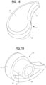
- FIGS 18-25 illustrate an embodiment of indicator flag cap 3 of a water level indicator in accordance the disclosure.
- the indicator flag cap may have a top surface 30, a side wall 31, an extension wall 32, a locking hole 33, and an inner cavity 34.
- the indicator flag cap 3 may be made of plastic, metal, or any other suitable material or combination of materials known in the art.
- the indicator flag caps 3 may have a teardrop shape as shown in Figures 18-25 , may be cylindrical, rectangular, or may have any other suitable shape desired by a person implementing the disclosed concepts.
- the top surface 30 of the indicator flag cap 3 should be sized so that it can be easily observable when the indicator flag cap 3 is pushed to the top of the upper housing 2.
- the edges of the top surface may be rounded or chamfered.
- the top surface may be sloped, or it may be flat, or have any suitable surface that can be observed when the indicator flag cap is pushed to the top of the upper housing.
- the side wall 31 is optional, and may also have any suitable shape and size.
- the side wall may be unitary or may comprise a plurality of sections.
- the extension wall 32 is also optional, may be unitary, or may comprise a plurality of sections.
- the extension wall 32 may extend beyond the side wall 31, or may reside within the side wall 31.
- the extension wall may define a locking hole 33 for receiving and securing a first end of a push rod 6.
- a push rod 6 may also be secured to the outer surface of the extension wall 32.
- the pushrod 6 may be secured to the locking hole 33 or to the extension wall 32 by any method known in the art, including without limitation, through the use of adhesives, friction fit connections, or detents and recesses.
- the indicator flag cap 3 may have an inner cavity 34 between the side wall 31 and the extension wall 32. This can save on cost by reducing the amount of material needed to make the indicator flag cap 3, and reducing its weight.
- the locking hole 33 may simply be a located in a bottom surface of the indicator flag cap, obviating the need for an extension wall or an inner cavity.
- the indicator flag caps 3 may also have features to restrict its range of motion such that it does not rise beyond the top of the upper housing 2. Any such features known in the art may be used, including without limitation, shaping and sizing the indicator flag caps 3 and the upper housing 2 so that the flags cannot exit the cavities 21 of the upper housing 2, or through the use of detents and recesses. Persons of skill in the art will recognize that numerous variations and alterations can be made to the structure of the indicator flag cap 3 within the scope of the disclosed concept.
- the indicator flag cap 3 may be made as a unitary structure with the pushrod 6. This unitary structure may also include the float cage 4 and/or floats. In such embodiments, the indicator flag cap 3 may have a structure similar to that shown in Figures 18-25 , or it may simply be the top surface of the pushrod 6. Persons of skill in the art will recognize that numerous variations and alterations can be made to the structure of the indicator flag cap 3, the pushrod 6, the floats 5 and float cages 4 within the scope of the disclosed concept, including without limitation combining one or more of them into unitary structures or keeping their respective structures separate.
- Figures 26-29 illustrate an embodiment of upper housing of a water indicator flag caps in the cavities.
- Figure 26 shows all three indicator flag caps in view in a raised position at the top of the upper housing. As discussed above, this occurs when the water level is high enough to push all of the float cages 4 and pushrods 6 up enough for the indicator flag caps 3 to be visible in this manner.
- Figure 27 shows only two indicator flag caps 3 in a raised position and visible at the top of the upper housing 2, which occurs when the water level is not high enough to push the float cage 4 with the shortest pushrod 6 up enough for its indicator flag cap 3 to show in the upper housing 2.
- Figure 28 shows only one indicator flag cap 3 in a raised position and visible at the top of the upper housing 2, which occurs when the water level is not high enough to push the float cage 4 with the intermediate pushrod 6 up enough for its indicator flag cap 3 to show in the upper housing 2.
- Figure 27 shows no indicator flag caps 3 visible at the top of the upper housing 2, which occurs when the water level is not high enough to push the float cage 4 with the longest pushrod 6 up enough for its indicator flag cap 3 to show in the upper housing 2.
- any number of indicator flag caps 3 may be used in accordance with the disclosed concepts.
- FIGS 30-36 illustrate an embodiment of top cap 8 of a water level indicator 1 in accordance with the disclosure.
- the top cap 8 may have a window 80, an outlet 81, a rim 82, a side wall 83, and a cut out 84.
- the top cap 8 may be made from plastic, glass, or any other material suitable or combination of materials known in the art.
- the top cap 8 may have a circular, or rectangular shape, or any other desired suitable shape.
- the top surface of the top cap 8 comprises a window 80 which may be sufficiently transparent or translucent to allow a user to observe the indicator flags 3 in the upper housing 2 through the window 80.
- the outlet 81 is optional and may be located anywhere on the top cap 8. It allows air to move in and out of the water level indicator as the indicator cap flags 3 move up or down.
- the rim 82 may be transparent, translucent or opaque, and may cover the area where the water level indicator connects to the self-watering planter 10 or other liquid container.
- the rim 82 may have a width (or diameter) that is greater that than that of the upper housing 2.
- the width (or diameter) of the rim 82 may also extend beyond the outer edge of the wings 25 of the upper housing.
- Side walls 83 may surround and receive the upper housing 2. As discussed above the side walls 83 may have any suitable shape, and may have a shape that is complementary to the shape of the upper housing 2.
- the side wall 83 may be a unitary structure, or may comprise several sections.
- the side wall 83 may have one or more cutouts 84, which are sized to accommodate the wings 25 of the upper housing 2. In some embodiments, the cut out may have a locking slot that is sized to receive and secure the wings 25 of the upper housing in order to secure the top cap to the upper housing. In this regard, cap 8 may be rotated such that wings 25 would engage adjacent locking slots.
- top cap 8 that is smaller than, and fits within the rim of the upper housing 2 may also be used within the scope of the disclosed concepts.
- Such embodiments may have an upper housing 2 that has internal structure, such as detents or other known structures, to secure the top cap within the upper housing.
- the top cap 8 cap may be detachable, or a person implementing the disclosed concepts may permanently attach the top cap 8 to the upper housing 2 through the use of adhesives, threading, or other known securing methods and structures.
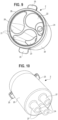
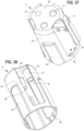
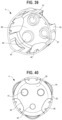
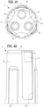
- FIGS 37-46 illustrate an embodiment of a float cage 4 of a water level indicator 1 in accordance with the disclosure.
- the float cage 4 may have a top surface 40, having through holes 41, a locking hole 42, an side wall 43, spacers 44, cutouts 45, float securing structures such as projections 46, and extension walls 47 which may include a cage floor 48.
- the float cage 4 may be made of metal, plastic, wood, or any other suitable material.
- the float cage 4 may house a single float 5, or a float made of multiple sections, or may itself act as and be integrated with the float, if it is made of a material that floats in water or the liquid contained in the self-watering planter 10 or other liquid container.
- the float cage 4 may be generally cylindrical, rectangular, or have any other desired suitable shape.
- the top surface 40 of the float may have through holes 41 which allow pushrods to slidably pass through the float cage 4.
- the through hole 41 may be sized to have a width (or diameter) greater than the width (or diameter) of the pushrod 6 in order to allow the pushrod 6 to slidably move through the through hole 41.
- the top surface may be absent, and the through hole may fill the entire space defined by the sidewall 43.
- a single through hole 41 may also be sized to allow multiple pushrods to pass through it.
- the top surface may also have a locking hole 42 that receives and secures the second end of a pushrod 6.
- the locking hole 42 may secure the pushrod 6 through the use of adhesives, a friction fit connection, detents and recesses, or any other method for securing such structures known or to be developed in the art.
- Figure 46 shows an alternative embodiment where the extension wall 47 descending from the on the locking hole 41 has a securing hole 49 which can receive a pin, or in the pushrod 6.
- a securing hole 49 which can receive a pin, or in the pushrod 6.
- Persons of skill in the art will recognize that numerous ways that the pushrod 6 can be secured to the locking hole 42 of the float cage 4 are contemplated within the scope of the disclosed concept.
- the locking hole 42 is not needed. Extension walls 47 may descend from either through-holes 41 or locking holes 42.
- the extension walls may be sized to receive and/or secure the through holes in floats 5 that are inserted into the float cage.
- Extension walls 47 descending from a locking hole 42 may have a floor 48.
- the float cage may also have a float securing structure, such as projections 46, or any other such structure known in the art. Projections 46 may secure the bottom floor 53 of the float 5 to keep the float 5 within the side wall 43 of the float cage 43.
- the side wall 43 of the float cage may be sized to receive and house the float 5, and to slidably pass through the shell 7.
- the side wall may have spacers 44 built into it, or added to its outer surface to separate the main body of the side wall 43, the float cage 4, and/or the float 5 from contacting the shell 7.
- the spacers 44 may be rounded, edged, projections, or have any other suitable shape or structure.
- the float cage 4 may also have cutouts 45 to reduce the amount of material needed for the float cage 4, the weight of the float cage 4, and/or to better accommodate the float 5.
- the sidewall 43 may be internal to the floats, and have them arranged along the outer sides of the side wall 43.
- the side wall 43 may act as the float 5, if it is made of a material that floats in water or any other liquid in the self-watering planter 10 or other liquid container. While the float 5 is described separately below, persons of skill in the art will recognize that the float 5 may be part of the float cage 4, forming an integrated or even a unitary structure with the float cage 4. Accordingly, a locking hole 42 of a float cage 4 may be disposed in float 5, within the scope of the disclosed concept.
- all of the float cages of the water level indicator 1 may be identical, as shown in Figures 2-8 and 37-44 .
- the bottom float cage 4, which secures the longest pushrod 6 in the water level indicator does not need through holes 41, and unnecessary through holes may be removed from the other float cages 4.
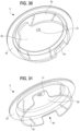
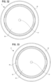
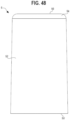
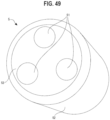
- FIGS 47-51 illustrate a float 5 of a water level indicator in accordance with an embodiment of the invention.
- the floats 5, 5a, 5b, 5c may have an upper surface 50, through holes 51, an outer surface 52, and a bottom surface 53.
- the upper surface may have a tapered portion 54 which is chamfered or rounded so as to be narrower than the width or diameter of the outer surface to facilitate insertion into a float cage 4.
- the float may be made from wood, Styrofoam, or any other suitable buoyant material or combination of materials that floats in the liquid that is contained in the liquid reservoir 16.
- the through holes 51 may be sized to allow the pushrods 6 to slidably pass through the float. Holes 51 may be uniformly sized or, in other embodiments, having differing sizes particularly. For instance, a one hole 51 may be smaller than the other holes so as to accommodate a friction fit of one push rod 6, while the other holes are larger to accommodate the other push rods 6 to pass through and remain slidable within their respective hole 51. In some embodiments the through holes 51 may be sized to receive the extension walls 47 of the float cage 4. In some such embodiments the through holes 51 of the float 5 may secure the extension walls 47 of the float cage 4 via a friction fit connection, or through any other securing method known in the art.
- a through hole 51 is securing an extension wall 47 descending from a locking hole, 42 of the float cage 4 and having an extension floor 48, such a through hole 51 may, but need not, extend through the entirety of the float 5.
- the bottom surface 53 of the float 5 may engage securing projections 46 in the float cage 4.
- the width or diameter of the outer surface float 5 may be consistent, or as shown in Figures 47-51 , may be greater at the bottom than the width or diameter at the top of the float.
- the floats may be generally cylindrical, rectangular, or have any other suitable shape.
- each float 5a, 5b, 5c may have the same shape as the other floats, or each float may have a different shape.
- each float 5, 5a, 5b, 5c may have the same number of through holes even though the lower floats do not need to allow as many pushrods to pass through them.
- each float may have only the number of through holes that it requires to allow the necessary pushrods 6 through or to secure the necessary number of extension walls.
- a float may have multiple through-holes, such as one for each pushrod that passes through, or may have a single through-hole allowing all such pushrods to pass through within the scope of the disclosed concepts.
- each float 5, 5a, 5b, 5c may be a unitary construction or may comprise multiple discreet float sections within the scope of the disclosed concept.
- the through hole in such embodiments may be the empty space between the parts of the float 5 which allow the pushrods to pass through.
- the disclosed concepts can also be implemented with the floats encompassing or surrounding the float cage, instead of secured within the float cage, as shown in Figures 2-8 and 55 . Again, in such embodiments, the through hole in the float 5 may be the empty space between the float sections, even where the float sections are exclusively located outside of the float cage 4.
- FIGS 52-54 illustrate pushrods 6 of a water level indicator 1 in accordance with an embodiment of the invention.
- the pushrods 6 may have a first end secured to an indicator flag cap 3, and a second end secured to a float cage 4.
- the length of each pushrod may be measured from the first end to the second end.
- each pushrod 6a, 6b, 6c has a different length.
- the pushrods may be sized to convey the desired water level.
- the longest pushrod 6c is sized such that the float 5c will push the indicator flag cap 3 connected to pushrod 6c to the top of the upper housing when the liquid reservoir 16 is one-third full.
- the intermediate pushrod 6b is sized such that the float 5b will push the indicator flag cap 3 connected to pushrod 6b to the top of the upper housing when the liquid reservoir 16 is two-thirds full.
- the smaller pushrod 6a is sized such that the float 5c will push the indicator flag cap 3 connected to pushrod 6c to the top of the upper housing when the liquid reservoir 16 is one-third full.
- the pushrods 6 may be cylindrical, rectangular, or any other suitable shape. They may have a consistent cross-section, or the cross section may vary. They should be sized such that the cross section of the pushrod 6 is smaller than, and slidably passes through the through holes 24, 41, 51 in the upper housing 2, float cage 4, and float 5.
- the pushrods may be made of plastic, metal or any other suitable material or combination of materials.
- the pushrods may have stops (not shown) on them at an appropriate distance from the bottom of the extension walls 27 of the upper housing to limit how far up they can push the indicator flag cap 3.
- Figure 55 illustrates a partially assembled indicator 1 showing a connected float 5, float cage 4, pushrod 6 and indicator flag cap 3.
- float 5 When the level of the liquid in the liquid reservoir 16 is higher than the bottom of the float 5, it begins to force the float 5 upwards, which in turn pushes the float cage 4, and the pushrod 6 secured to that float rod upwards, which in turn pushes the indicator flag cap 3.
- the indicator flag cap 3 When the liquid is at a sufficient level, the indicator flag cap 3 is pushed to the top of its respective cavity 21 the upper housing 2, where it can be easily seen by an observer.
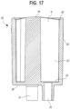
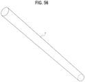
- FIG 56 illustrates an embodiment of shell 7 of a water level indicator in accordance with the disclosure.
- the shell 7 houses the interior components of the water level indicator 1, including the float cages 4, floats 5, and pushrods 6.
- the shell 7 may have a first end that is secured over the outer wall 23 of the upper housing 2, and a second end that is secured over the bottom cap 9.
- the shape of the shell 7 may be cylindrical, square, or any other suitable shape.
- the shape of the shell 7 may be complementary to the upper housing 2 and/or the bottom cap 9 where those structures are secured to the shell.
- Shell 7 may be in fluid communication with reservoir 16 to permit liquid to enter into shell 7 proportionally to liquid fill-level of reservoir 16.
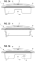
- FIGS 57-59 illustrate a bottom cap 9 of a water level indicator 1 in accordance with an embodiment of the invention.
- the bottom cap 9 may attach to the bottom of the shell 7.
- the bottom cap 9 may have a bottom floor 90 which may have an inlet 91.
- the bottom floor 90 may also have an outer rim 94.
- a sidewall 92 may extend upwards from the bottom floor 90.
- the sidewall 92 may have a tapered portion 93 that may be sloped or chamfered to facilitate securing the bottom cap to the shell.
- the bottom cap 9 may be made of plastic, metal, or any other suitable material or combination of materials.
- the inlet 91 in the floor allows water to enter the interior of the shell 7, and interact with the floats 5 and float cages 4.
- the bottom cap may have a circular or square shape, or any other desired suitable shape.
- the side wall 92 of the bottom cap 9 should have a shape complementary to the shape of the shell.
- the side may comprise multiple side walls.
- the sidewall 92 may fit within the shell 7.
- the floor may have a rim 94, that extends beyond the side walls 92 and that may receive the ends of the shell 7.
- the bottom cap 9 may be rim-less, and may fit entirely within the shell 7.
- the sidewall 92 of bottom cap 9 may attach over the shell 7.
- the bottom cap 9 may be secured to the shell 7 in any manner known in the art, including without limitation through the use of adhesives, friction fits, threading, projections and recesses, and locking pins. As discussed above with respect to the top cap 8, the bottom cap 9 may be detachable or may be permanently secured to the shell 7. In other some embodiments the bottom cap 9 may be part of the shell 7, and of unitary construction with the shell 7.
Landscapes
- Physics & Mathematics (AREA)
- Fluid Mechanics (AREA)
- General Physics & Mathematics (AREA)
- Engineering & Computer Science (AREA)
- Water Supply & Treatment (AREA)
- Life Sciences & Earth Sciences (AREA)
- Environmental Sciences (AREA)
- Level Indicators Using A Float (AREA)
- Cultivation Receptacles Or Flower-Pots, Or Pots For Seedlings (AREA)
Claims (15)
- Wasserstandsanzeiger (1), Folgendes umfassend:• eine Hülle (7), die ein oberes Ende und ein unteres Ende aufweist,• mehrere Schubstangen (6, 6a-6c), die in der Hülle angeordnet sind, wobei jede der Schubstangen ein erstes Ende und ein zweites Ende aufweist, welche eine Länge definieren, die sich von der Länge der anderen Schubstangen der mehreren Schubstangen unterscheidet,• mehrere Schwimmer (5, 5a-5c), wobei jeder Schwimmer eine Arretierungsöffnung umfasst, die ein zweites Ende einer der mehreren Schubstangen aufnimmt und sichert, und wobei mindestens einer der mehreren Schwimmer mindestens eine Durchgangsöffnung umfasst, die das Hindurchtreten der Schubstange(n), die nicht an dem Schwimmer gesichert ist/sind, durch den Schwimmer ermöglicht, und• ein oberes Gehäuse (2), das einen oder mehrere Hohlräume umfasst, wobei in dem einen oder den mehreren Hohlräumen in dem oberen Gehäuse mehrere Anzeigermarkierungskappen (3, 3a-3c) angeordnet sind, wobei das erste Ende jeder Schubstange der mehreren Schubstangen mit einer anderen Anzeigermarkierungskappe verbunden istwobei die Hülle im Wesentlichen das obere Gehäuse, die mehreren Anzeigermarkierungskappen, die mehreren Schubstangen und die mehreren Schwimmer umschließt,wobei die Anzeigermarkierungskappe jeder Schubstange im Gebrauch in einem Flüssigkeitsbehälter zur Oberseite des oberen Gehäuses geschoben wird, wenn der Flüssigkeitsbehälter auf verschiedene Füllstände gefüllt wird, und wobei sich alle Anzeigermarkierungskappen im Gebrauch in dem Flüssigkeitsbehälter, wenn der Flüssigkeitsbehälter bei oder nahezu bei 100 % seiner Kapazität ist, in einer angehobenen Position an der Oberseite des oberen Gehäuses befinden.
- Wasserstandsanzeiger (1) nach Anspruch 1, wobei jede Schubstange und ihre entsprechende Anzeigermarkierungskappe eine unitäre Struktur sind.
- Wasserstandsanzeiger (1) nach einem der Ansprüche 1 bis 2, wobei jeder Schwimmer ferner einen Schwimmerkäfig umfasst, wobei die Arretierungsöffnung in jedem der mehreren Schimmer in seinem entsprechenden Schwimmerkäfig angeordnet ist.
- Wasserstandsanzeiger (1) nach Anspruch 3, wobei jeder Schwimmer mit seinem entsprechenden Schwimmerkäfig eine unitäre Struktur ist.
- Wasserstandsanzeiger (1) nach Anspruch 3 oder 4, wobei die Schwimmerkäfige ferner einen Abstandshalter umfassen, der die Seiten der Schwimmerkäfige von der Hülle trennt.
- Wasserstandsanzeiger (1) nach Anspruch 2 oder 3, wobei das obere Gehäuse nahe dem oberen Ende der Hülle angeordnet ist.
- Wasserstandsanzeiger (1) nach einem der vorhergehenden Ansprüche 1 bis 5, wobei das obere Gehäuse ferner Arretierungsflügel umfasst.
- Wasserstandsanzeiger (1) nach einem der vorhergehenden Ansprüche 1 bis 7, wobei der eine oder die mehreren Hohlräume des oberen Gehäuses mehrere Hohlräume sind, die einen ersten Hohlraum, einen zweiten Hohlraum und einen dritten Hohlraum beinhalten.
- Wasserstandsanzeiger (1) nach einem der vorhergehenden Ansprüche, wobei die mehreren Schubstangen eine erste Schubstange, eine zweite Schubstange und eine dritte Schubstange umfassen.
- Wasserstandsanzeiger (1) nach Anspruch 1,wobei die mehreren Schubstangen eine erste Schubstange, eine zweite Schubstange und eine dritte Schubstange umfassen,wobei die mehreren Schwimmer einen ersten Schwimmer, einen zweiten Schwimmer und einen dritten Schwimmer umfassen und wobei der erste Schwimmer die erste Schubstange in seiner Arretierungsöffnung aufnimmt und sichert, der zweite Schwimmer die zweite Schubstange in seiner Arretierungsöffnung aufnimmt und sichert und der dritte Schwimmer die dritte Schubstange in seiner Arretierungsöffnung aufnimmt und sichert undwobei der erste Schwimmer mindestens zwei Durchgangsöffnungen umfasst, die das Hindurchtreten der zweiten und der dritten Schubstange der mehreren Schubstangen durch den ersten Schwimmer ermöglichen, und der zweite Schwimmer mindestens eine Durchgangsöffnung umfasst, die das Hindurchtreten der dritten Schubstange durch den zweiten Schwimmer ermöglicht.
- Wasserstandsanzeiger (1) nach Anspruch 10, ferner Folgendes umfassend:- mehrere Schwimmerkäfige, die einen ersten Schwimmerkäfig, einen zweiten Schwimmerkäfig und einen dritten Schwimmerkäfig umfassen,wobei jeder Schwimmer der mehreren Schwimmer in einem der mehreren Schwimmerkäfige angeordnet ist, so dass der erste Schwimmer in dem ersten Schwimmerkäfig angeordnet ist, der zweite Schwimmer in dem zweiten Schwimmerkäfig angeordnet ist und der dritte Schwimmer in dem dritten Schwimmerkäfig angeordnet ist.
- Wasserstandsanzeiger (1) nach Anspruch 10 oder Anspruch 11,
wobei das erste Ende der ersten Schubstange mit einer ersten Anzeigermarkierungskappe verbunden ist, das erste Ende der zweiten Schubstange mit einer zweiten Anzeigermarkierungskappe verbunden ist und das erste Ende der dritten Schubstange mit einer dritten Anzeigermarkierungskappe verbunden ist. - Wasserstandsanzeiger (1) nach Anspruch 1,wobei das obere Gehäuse mindestens drei Hohlräume umfasst, die einen ersten Hohlraum, einen zweiten Hohlraum und einen dritten Hohlraum beinhalten, wobei in jedem Hohlraum in dem oberen Gehäuse eine Anzeigermarkierungskappe angeordnet ist,wobei der Wasserstandsanzeiger ferner mehrere Schwimmerkäfige umfasst, die einen ersten Schwimmerkäfig, einen zweiten Schwimmerkäfig und einen dritten Schwimmerkäfig beinhalten,wobei die mehreren Schubstangen mindestens drei Schubstangen umfassen, die eine erste Schubstange, eine zweite Schubstange und eine dritte Schubstange beinhalten,wobei das erste Ende der ersten Schubstange mit der Anzeigermarkierungskappe in dem ersten Hohlraum des oberen Gehäuses verbunden ist, das erste Ende der zweiten Schubstange mit der Anzeigermarkierungskappe in dem zweiten Hohlraum des oberen Gehäuses verbunden ist und das erste Ende der dritten Schubstange mit der Anzeigermarkierungskappe in dem dritten Hohlraum des oberen Gehäuses verbunden ist,wobei die mehreren Schwimmer einen ersten Schwimmer, einen zweiten Schwimmer und einen dritten Schwimmer umfassen,wobei jeder Schwimmer der mehreren Schwimmer in einem der mehreren Schwimmerkäfige angeordnet ist, so dass der erste Schwimmer in dem ersten Schwimmerkäfig angeordnet ist, der zweite Schwimmer in dem zweiten Schwimmerkäfig angeordnet ist und der dritte Schwimmer in dem dritten Schwimmerkäfig angeordnet ist,wobei jeder Schwimmerkäfig eine Arretierungsöffnung umfasst, die ein zweites Ende von einer der mehreren Schubstangen aufnimmt und sichert, so dass der erste Schwimmerkäfig die erste Schubstange in seiner Arretierungsöffnung aufnimmt und sichert, der zweite Schwimmerkäfig die zweite Schubstange in seiner Arretierungsöffnung aufnimmt und sichert und der dritte Schwimmerkäfig die dritte Schubstange in seiner Arretierungsöffnung aufnimmt und sichert, undder erste Schwimmerkäfig und ein erster Schwimmer jeweils mindestens zwei Durchgangsöffnungen umfassen, die das Hindurchtreten der zweiten und der dritten Schubstange der mehreren Schubstangen durch den ersten Schwimmerkäfig und den ersten Schwimmer ermöglichen, und der zweite Schwimmerkäfig und der zweite Schwimmer mindestens eine Durchgangsöffnung umfassen, die das Hindurchtreten der dritten Schubstange durch den zweiten Schwimmerkäfig und den zweiten Schwimmer ermöglicht.
- Selbstbewässerndes Pflanzgefäß (10), Folgendes umfassend:- eine Innenwand und einen Boden, die einen Pflanzenhohlraum definieren,- eine Außenwand, die ein Wasserreservoir umgibt,- einen Einlass, der das Eintreten von Wasser in das Wasserreservoir ermöglicht, und- die Wasserstandsanzeiger (1) nach einem der Ansprüche 1 bis 13.
- Selbstbewässerndes Pflanzgefäß (10) nach Anspruch 14, wobei:- der Wasserstandsanzeiger der Wasserstandsanzeiger (1) nach Anspruch13 ist.
Applications Claiming Priority (2)
| Application Number | Priority Date | Filing Date | Title |
|---|---|---|---|
| US14/864,362 US9872446B2 (en) | 2015-09-24 | 2015-09-24 | Liquid level indicator |
| PCT/US2016/053468 WO2017053814A1 (en) | 2015-09-24 | 2016-09-23 | Liquid level indicator |
Publications (4)
| Publication Number | Publication Date |
|---|---|
| EP3353509A1 EP3353509A1 (de) | 2018-08-01 |
| EP3353509A4 EP3353509A4 (de) | 2019-05-22 |
| EP3353509C0 EP3353509C0 (de) | 2023-07-12 |
| EP3353509B1 true EP3353509B1 (de) | 2023-07-12 |
Family
ID=58385414
Family Applications (1)
| Application Number | Title | Priority Date | Filing Date |
|---|---|---|---|
| EP16849759.2A Active EP3353509B1 (de) | 2015-09-24 | 2016-09-23 | Flüssigkeitsstandanzeiger |
Country Status (4)
| Country | Link |
|---|---|
| US (2) | US9872446B2 (de) |
| EP (1) | EP3353509B1 (de) |
| CA (1) | CA2922586C (de) |
| WO (1) | WO2017053814A1 (de) |
Families Citing this family (4)
| Publication number | Priority date | Publication date | Assignee | Title |
|---|---|---|---|---|
| USD876986S1 (en) * | 2017-01-26 | 2020-03-03 | Dotchi, Llc | Planter with indicator shelf |
| US10561072B2 (en) * | 2017-11-13 | 2020-02-18 | Aqualean Manufacturing Associates Co., Ltd. | Plant cultivating container |
| EP3556202B1 (de) * | 2018-04-17 | 2023-06-07 | Dotchi, LLC | Wasserstandsanzeiger |
| US11528850B2 (en) | 2018-07-20 | 2022-12-20 | Dotchi, Llc | Insertable planter, system, and methods |
Family Cites Families (38)
| Publication number | Priority date | Publication date | Assignee | Title |
|---|---|---|---|---|
| US1185985A (en) * | 1914-09-21 | 1916-06-06 | Charles Brownlow Miller | Liquid-gage. |
| FR504798A (fr) * | 1919-10-11 | 1920-07-16 | Louis Badois | Dispositif indicateur de niveau télescopique |
| US1768946A (en) * | 1924-10-23 | 1930-07-01 | Protectoseal Co | Liquid-level indicator |
| GB471706A (en) * | 1935-11-07 | 1937-09-09 | Eumuco Ag Fuer Maschinenbau | Improvements in or relating to control devices for hydraulic accumulators |
| US2510663A (en) * | 1947-01-17 | 1950-06-06 | Horace Hayne | Tank gauge |
| US2777914A (en) * | 1953-10-08 | 1957-01-15 | Reliance Gauge Column Company | Magnetic switch |
| DE1195504B (de) * | 1961-12-06 | 1965-06-24 | Agfa Ag | Niveauschaltvorrichtung fuer Fluessigkeitsbehaelter |
| US3359798A (en) * | 1965-02-08 | 1967-12-26 | Crosweller & Co Ltd W | Liquid level indicators |
| US3552058A (en) | 1968-04-22 | 1971-01-05 | James C Fici | Planter with reservoir |
| US3595267A (en) * | 1969-03-17 | 1971-07-27 | Wyandotte Chemicals Corp | Liquid level control device |
| US3775904A (en) | 1971-07-06 | 1973-12-04 | Universal Prod Dev Corp | Self-watering flower pot |
| SE363566B (de) * | 1973-01-04 | 1974-01-28 | Husqvarna Borstfab Ab | |
| US4528774A (en) | 1974-09-06 | 1985-07-16 | Vivian A. Skaife | Plant and seed growing system |
| US4092861A (en) * | 1977-02-14 | 1978-06-06 | Fling William F | Liquid level measuring device |
| US4335540A (en) * | 1980-11-28 | 1982-06-22 | Allen Ron P | Combined plant container and watering device |
| DE3323046C1 (de) * | 1983-06-27 | 1984-07-19 | Klaus 7505 Ettlingen Zschernitz | Wasserstandsanzeiger für Pflanzgefäße, insbesondere für Hydrokulturen |
| GB8415308D0 (en) | 1984-06-15 | 1984-07-18 | Fong H | Plant container |
| US4916858A (en) * | 1987-08-03 | 1990-04-17 | Rubbermaid Incorporated | Self-watering planter |
| CN2031197U (zh) | 1988-03-01 | 1989-01-25 | 李彩彬 | 可调节自湿式花盆 |
| US5079950A (en) * | 1990-05-03 | 1992-01-14 | Sealand Technology, Inc. | Level indicating in vehicle holding tanks |
| EP0464977A1 (de) * | 1990-07-03 | 1992-01-08 | Zentralinstitut Für Festkörperphysik Und Werkstofforschung | Füllstandsmesser mit Korrosions- und Verkrustungsschutz |
| US5294917A (en) * | 1992-04-06 | 1994-03-15 | Wilkins Larry C | Liquid level sensor using float and magnetic means |
| US6226921B1 (en) * | 1999-02-22 | 2001-05-08 | Gaasbeck U.S.A., Inc. | Self-watering planter |
| US6345470B1 (en) | 1999-11-11 | 2002-02-12 | Fashion Nails, Inc. | Self-contained automatic watering system for indoor or outdoor plants |
| ITRM20000130A1 (it) | 2000-03-14 | 2001-09-14 | Giampiero Fidotti | Vaso a riserva d'acqua per la coltivazione di piante da appartamento. |
| JP2004242501A (ja) | 2001-09-28 | 2004-09-02 | Suntry Flowers Ltd | 植物栽培方法及び植物栽培具及び植栽容器 |
| US8191310B2 (en) | 2003-08-13 | 2012-06-05 | John Rodney Keats | Stackable plant pot |
| DE10358688A1 (de) | 2003-12-12 | 2005-07-07 | Kronimus Ag | Pflanzbehälter |
| US7043983B2 (en) * | 2003-12-15 | 2006-05-16 | Fling William F | Horizontal liquid level measuring device |
| CH697286B1 (de) | 2005-01-13 | 2008-08-15 | Iup Inst Fuer Umweltpflege Ag | Wasserstand-Messvorrichtung für Pflanzengefässe. |
| DE102005058436A1 (de) | 2005-12-07 | 2007-06-14 | Werner Krachtus | Vorrichtung zur Messung und Anzeige der Feuchtigkeit in einem Erdreich |
| US7703240B2 (en) | 2007-12-14 | 2010-04-27 | Milton Watson | Automatic subterranean watering device |
| EP2108250A1 (de) | 2008-04-11 | 2009-10-14 | MinAqua ApS | System und Verfahren zur Steuerung des Pflanzenwachstums |
| DE102008049361A1 (de) * | 2008-09-29 | 2010-04-08 | Geobra Brandstätter GmbH & Co KG | Einsatz-Behälter |
| US8434634B2 (en) * | 2010-05-13 | 2013-05-07 | Bemis Manufacturing Company | Ratcheting gauge cap |
| DE102012205219A1 (de) | 2012-03-30 | 2013-10-02 | Klaus Schuler GmbH | Vorrichtung zum Aufnehmen eines Pflanzentopfes |
| US9681613B2 (en) * | 2013-09-23 | 2017-06-20 | Steven C. Stanford | Water-level indicator and wide-mouth re-fill apparatus for sub-irrigated, containerized plants that attaches to a plant's growpot |
| WO2016130119A1 (en) * | 2015-02-11 | 2016-08-18 | Lone Star Leak Detection, Llc | Liquid level monitoring for reservoirs |
-
2015
- 2015-09-24 US US14/864,362 patent/US9872446B2/en active Active
-
2016
- 2016-03-03 CA CA2922586A patent/CA2922586C/en active Active
- 2016-09-23 EP EP16849759.2A patent/EP3353509B1/de active Active
- 2016-09-23 WO PCT/US2016/053468 patent/WO2017053814A1/en not_active Ceased
-
2017
- 2017-12-07 US US15/834,278 patent/US10285346B2/en active Active
Also Published As
| Publication number | Publication date |
|---|---|
| EP3353509A4 (de) | 2019-05-22 |
| US9872446B2 (en) | 2018-01-23 |
| EP3353509C0 (de) | 2023-07-12 |
| US10285346B2 (en) | 2019-05-14 |
| US20180116136A1 (en) | 2018-05-03 |
| CA2922586C (en) | 2021-02-16 |
| WO2017053814A1 (en) | 2017-03-30 |
| EP3353509A1 (de) | 2018-08-01 |
| CA2922586A1 (en) | 2017-03-24 |
| US20170086398A1 (en) | 2017-03-30 |
Similar Documents
| Publication | Publication Date | Title |
|---|---|---|
| US10285346B2 (en) | Water level indicator | |
| ES2302286T3 (es) | Estructura de maceta. | |
| US10285347B2 (en) | Water level indicator | |
| EP3556202B1 (de) | Wasserstandsanzeiger | |
| ITUD20030054U1 (it) | Imbuto con indicatore per mostrare il livello dell'acqua | |
| ES2535514T3 (es) | Sistema de pesca que comprende un señuelo y cebo que comprende tal sistema de pesca | |
| CA2989748A1 (en) | Time measuring device | |
| CN205813330U (zh) | 一种渔具箱 | |
| US9049847B1 (en) | Aquarium fish partition device | |
| CN104170711A (zh) | 植物幼苗培养盒 | |
| ITMI940279A1 (it) | Scatola per il confezionamento di vermi per la pesca | |
| JP2013142599A (ja) | 液位測定手段を備えた液体貯溜装置 | |
| RU121363U1 (ru) | Указатель горизонтальной плоскости | |
| US20060034940A1 (en) | Drinking water container containing gemstones and crystals | |
| KR101987117B1 (ko) | 잔여량의 사용이 가능한 액체질소통 | |
| CN212982451U (zh) | 一种新型漏斗 | |
| KR20100010730U (ko) | 자석을 이용한 부착식 부화통 | |
| JP4052124B2 (ja) | 余浮力調整ウキ | |
| CN207448346U (zh) | 基建领域中用于固定螺钉的承装器 | |
| KR100580527B1 (ko) | 리저버 탱크 | |
| KR100973257B1 (ko) | 우산꽂이 | |
| CN202873547U (zh) | 水产养殖筐 | |
| TWI265131B (en) | A tubular container with multiple partitioned-tubes | |
| ITNA20130052A1 (it) | Contenitore e miscelatore modulare | |
| ES1064582U (es) | Señuelo polivalente para pesca. |
Legal Events
| Date | Code | Title | Description |
|---|---|---|---|
| STAA | Information on the status of an ep patent application or granted ep patent |
Free format text: STATUS: THE INTERNATIONAL PUBLICATION HAS BEEN MADE |
|
| PUAI | Public reference made under article 153(3) epc to a published international application that has entered the european phase |
Free format text: ORIGINAL CODE: 0009012 |
|
| STAA | Information on the status of an ep patent application or granted ep patent |
Free format text: STATUS: REQUEST FOR EXAMINATION WAS MADE |
|
| 17P | Request for examination filed |
Effective date: 20180315 |
|
| AK | Designated contracting states |
Kind code of ref document: A1 Designated state(s): AL AT BE BG CH CY CZ DE DK EE ES FI FR GB GR HR HU IE IS IT LI LT LU LV MC MK MT NL NO PL PT RO RS SE SI SK SM TR |
|
| AX | Request for extension of the european patent |
Extension state: BA ME |
|
| DAV | Request for validation of the european patent (deleted) | ||
| DAX | Request for extension of the european patent (deleted) | ||
| A4 | Supplementary search report drawn up and despatched |
Effective date: 20190426 |
|
| RIC1 | Information provided on ipc code assigned before grant |
Ipc: A01G 27/00 20060101ALI20190418BHEP Ipc: G01F 23/58 20060101ALI20190418BHEP Ipc: G01F 23/30 20060101AFI20190418BHEP |
|
| STAA | Information on the status of an ep patent application or granted ep patent |
Free format text: STATUS: EXAMINATION IS IN PROGRESS |
|
| 17Q | First examination report despatched |
Effective date: 20211014 |
|
| GRAP | Despatch of communication of intention to grant a patent |
Free format text: ORIGINAL CODE: EPIDOSNIGR1 |
|
| STAA | Information on the status of an ep patent application or granted ep patent |
Free format text: STATUS: GRANT OF PATENT IS INTENDED |
|
| INTG | Intention to grant announced |
Effective date: 20230203 |
|
| GRAS | Grant fee paid |
Free format text: ORIGINAL CODE: EPIDOSNIGR3 |
|
| GRAA | (expected) grant |
Free format text: ORIGINAL CODE: 0009210 |
|
| STAA | Information on the status of an ep patent application or granted ep patent |
Free format text: STATUS: THE PATENT HAS BEEN GRANTED |
|
| AK | Designated contracting states |
Kind code of ref document: B1 Designated state(s): AL AT BE BG CH CY CZ DE DK EE ES FI FR GB GR HR HU IE IS IT LI LT LU LV MC MK MT NL NO PL PT RO RS SE SI SK SM TR |
|
| REG | Reference to a national code |
Ref country code: CH Ref legal event code: EP |
|
| REG | Reference to a national code |
Ref country code: DE Ref legal event code: R096 Ref document number: 602016081044 Country of ref document: DE |
|
| REG | Reference to a national code |
Ref country code: IE Ref legal event code: FG4D |
|
| U01 | Request for unitary effect filed |
Effective date: 20230811 |
|
| U07 | Unitary effect registered |
Designated state(s): AT BE BG DE DK EE FI FR IT LT LU LV MT NL PT SE SI Effective date: 20230818 |
|
| U20 | Renewal fee for the european patent with unitary effect paid |
Year of fee payment: 8 Effective date: 20230921 |
|
| REG | Reference to a national code |
Ref country code: LT Ref legal event code: MG9D |
|
| PG25 | Lapsed in a contracting state [announced via postgrant information from national office to epo] |
Ref country code: GR Free format text: LAPSE BECAUSE OF FAILURE TO SUBMIT A TRANSLATION OF THE DESCRIPTION OR TO PAY THE FEE WITHIN THE PRESCRIBED TIME-LIMIT Effective date: 20231013 |
|
| PG25 | Lapsed in a contracting state [announced via postgrant information from national office to epo] |
Ref country code: ES Free format text: LAPSE BECAUSE OF FAILURE TO SUBMIT A TRANSLATION OF THE DESCRIPTION OR TO PAY THE FEE WITHIN THE PRESCRIBED TIME-LIMIT Effective date: 20230712 |
|
| PG25 | Lapsed in a contracting state [announced via postgrant information from national office to epo] |
Ref country code: IS Free format text: LAPSE BECAUSE OF FAILURE TO SUBMIT A TRANSLATION OF THE DESCRIPTION OR TO PAY THE FEE WITHIN THE PRESCRIBED TIME-LIMIT Effective date: 20231112 |
|
| PG25 | Lapsed in a contracting state [announced via postgrant information from national office to epo] |
Ref country code: RS Free format text: LAPSE BECAUSE OF FAILURE TO SUBMIT A TRANSLATION OF THE DESCRIPTION OR TO PAY THE FEE WITHIN THE PRESCRIBED TIME-LIMIT Effective date: 20230712 Ref country code: NO Free format text: LAPSE BECAUSE OF FAILURE TO SUBMIT A TRANSLATION OF THE DESCRIPTION OR TO PAY THE FEE WITHIN THE PRESCRIBED TIME-LIMIT Effective date: 20231012 Ref country code: IS Free format text: LAPSE BECAUSE OF FAILURE TO SUBMIT A TRANSLATION OF THE DESCRIPTION OR TO PAY THE FEE WITHIN THE PRESCRIBED TIME-LIMIT Effective date: 20231112 Ref country code: HR Free format text: LAPSE BECAUSE OF FAILURE TO SUBMIT A TRANSLATION OF THE DESCRIPTION OR TO PAY THE FEE WITHIN THE PRESCRIBED TIME-LIMIT Effective date: 20230712 Ref country code: GR Free format text: LAPSE BECAUSE OF FAILURE TO SUBMIT A TRANSLATION OF THE DESCRIPTION OR TO PAY THE FEE WITHIN THE PRESCRIBED TIME-LIMIT Effective date: 20231013 Ref country code: ES Free format text: LAPSE BECAUSE OF FAILURE TO SUBMIT A TRANSLATION OF THE DESCRIPTION OR TO PAY THE FEE WITHIN THE PRESCRIBED TIME-LIMIT Effective date: 20230712 |
|
| PG25 | Lapsed in a contracting state [announced via postgrant information from national office to epo] |
Ref country code: PL Free format text: LAPSE BECAUSE OF FAILURE TO SUBMIT A TRANSLATION OF THE DESCRIPTION OR TO PAY THE FEE WITHIN THE PRESCRIBED TIME-LIMIT Effective date: 20230712 |
|
| REG | Reference to a national code |
Ref country code: DE Ref legal event code: R097 Ref document number: 602016081044 Country of ref document: DE |
|
| PG25 | Lapsed in a contracting state [announced via postgrant information from national office to epo] |
Ref country code: SM Free format text: LAPSE BECAUSE OF FAILURE TO SUBMIT A TRANSLATION OF THE DESCRIPTION OR TO PAY THE FEE WITHIN THE PRESCRIBED TIME-LIMIT Effective date: 20230712 Ref country code: RO Free format text: LAPSE BECAUSE OF FAILURE TO SUBMIT A TRANSLATION OF THE DESCRIPTION OR TO PAY THE FEE WITHIN THE PRESCRIBED TIME-LIMIT Effective date: 20230712 Ref country code: CZ Free format text: LAPSE BECAUSE OF FAILURE TO SUBMIT A TRANSLATION OF THE DESCRIPTION OR TO PAY THE FEE WITHIN THE PRESCRIBED TIME-LIMIT Effective date: 20230712 Ref country code: SK Free format text: LAPSE BECAUSE OF FAILURE TO SUBMIT A TRANSLATION OF THE DESCRIPTION OR TO PAY THE FEE WITHIN THE PRESCRIBED TIME-LIMIT Effective date: 20230712 |
|
| REG | Reference to a national code |
Ref country code: CH Ref legal event code: PL |
|
| PLBE | No opposition filed within time limit |
Free format text: ORIGINAL CODE: 0009261 |
|
| STAA | Information on the status of an ep patent application or granted ep patent |
Free format text: STATUS: NO OPPOSITION FILED WITHIN TIME LIMIT |
|
| PG25 | Lapsed in a contracting state [announced via postgrant information from national office to epo] |
Ref country code: MC Free format text: LAPSE BECAUSE OF FAILURE TO SUBMIT A TRANSLATION OF THE DESCRIPTION OR TO PAY THE FEE WITHIN THE PRESCRIBED TIME-LIMIT Effective date: 20230712 |
|
| 26N | No opposition filed |
Effective date: 20240415 |
|
| REG | Reference to a national code |
Ref country code: IE Ref legal event code: MM4A |
|
| PG25 | Lapsed in a contracting state [announced via postgrant information from national office to epo] |
Ref country code: IE Free format text: LAPSE BECAUSE OF NON-PAYMENT OF DUE FEES Effective date: 20230923 |
|
| PG25 | Lapsed in a contracting state [announced via postgrant information from national office to epo] |
Ref country code: CH Free format text: LAPSE BECAUSE OF NON-PAYMENT OF DUE FEES Effective date: 20230930 |
|
| PG25 | Lapsed in a contracting state [announced via postgrant information from national office to epo] |
Ref country code: IE Free format text: LAPSE BECAUSE OF NON-PAYMENT OF DUE FEES Effective date: 20230923 Ref country code: CH Free format text: LAPSE BECAUSE OF NON-PAYMENT OF DUE FEES Effective date: 20230930 |
|
| U20 | Renewal fee for the european patent with unitary effect paid |
Year of fee payment: 9 Effective date: 20240920 |
|
| PG25 | Lapsed in a contracting state [announced via postgrant information from national office to epo] |
Ref country code: CY Free format text: LAPSE BECAUSE OF FAILURE TO SUBMIT A TRANSLATION OF THE DESCRIPTION OR TO PAY THE FEE WITHIN THE PRESCRIBED TIME-LIMIT; INVALID AB INITIO Effective date: 20160923 |
|
| PG25 | Lapsed in a contracting state [announced via postgrant information from national office to epo] |
Ref country code: HU Free format text: LAPSE BECAUSE OF FAILURE TO SUBMIT A TRANSLATION OF THE DESCRIPTION OR TO PAY THE FEE WITHIN THE PRESCRIBED TIME-LIMIT; INVALID AB INITIO Effective date: 20160923 |
|
| PGFP | Annual fee paid to national office [announced via postgrant information from national office to epo] |
Ref country code: GB Payment date: 20250925 Year of fee payment: 10 |
|
| U20 | Renewal fee for the european patent with unitary effect paid |
Year of fee payment: 10 Effective date: 20250922 |
|
| PG25 | Lapsed in a contracting state [announced via postgrant information from national office to epo] |
Ref country code: TR Free format text: LAPSE BECAUSE OF FAILURE TO SUBMIT A TRANSLATION OF THE DESCRIPTION OR TO PAY THE FEE WITHIN THE PRESCRIBED TIME-LIMIT Effective date: 20230712 |