EP3353855B1 - Structure déployable destinée à être utilisée dans l'établissement d'une antenne à réseau réflecteur - Google Patents
Structure déployable destinée à être utilisée dans l'établissement d'une antenne à réseau réflecteur Download PDFInfo
- Publication number
- EP3353855B1 EP3353855B1 EP16849901.0A EP16849901A EP3353855B1 EP 3353855 B1 EP3353855 B1 EP 3353855B1 EP 16849901 A EP16849901 A EP 16849901A EP 3353855 B1 EP3353855 B1 EP 3353855B1
- Authority
- EP
- European Patent Office
- Prior art keywords
- pantograph
- reflectarray
- endless
- tape
- deployed
- Prior art date
- Legal status (The legal status is an assumption and is not a legal conclusion. Google has not performed a legal analysis and makes no representation as to the accuracy of the status listed.)
- Active
Links
Images





Classifications
-
- H—ELECTRICITY
- H01—ELECTRIC ELEMENTS
- H01Q—ANTENNAS, i.e. RADIO AERIALS
- H01Q15/00—Devices for reflection, refraction, diffraction or polarisation of waves radiated from an antenna, e.g. quasi-optical devices
- H01Q15/14—Reflecting surfaces; Equivalent structures
-
- B—PERFORMING OPERATIONS; TRANSPORTING
- B64—AIRCRAFT; AVIATION; COSMONAUTICS
- B64G—COSMONAUTICS; VEHICLES OR EQUIPMENT THEREFOR
- B64G1/00—Cosmonautic vehicles
- B64G1/22—Parts of, or equipment specially adapted for fitting in or to, cosmonautic vehicles
- B64G1/222—Parts of, or equipment specially adapted for fitting in or to, cosmonautic vehicles for deploying structures between a stowed and deployed state
- B64G1/2221—Parts of, or equipment specially adapted for fitting in or to, cosmonautic vehicles for deploying structures between a stowed and deployed state characterised by the manner of deployment
- B64G1/2222—Folding
- B64G1/2223—Folding via scissor linkage
-
- B—PERFORMING OPERATIONS; TRANSPORTING
- B64—AIRCRAFT; AVIATION; COSMONAUTICS
- B64G—COSMONAUTICS; VEHICLES OR EQUIPMENT THEREFOR
- B64G1/00—Cosmonautic vehicles
- B64G1/22—Parts of, or equipment specially adapted for fitting in or to, cosmonautic vehicles
- B64G1/222—Parts of, or equipment specially adapted for fitting in or to, cosmonautic vehicles for deploying structures between a stowed and deployed state
- B64G1/2229—Parts of, or equipment specially adapted for fitting in or to, cosmonautic vehicles for deploying structures between a stowed and deployed state characterised by the deployment actuating mechanism
-
- B—PERFORMING OPERATIONS; TRANSPORTING
- B64—AIRCRAFT; AVIATION; COSMONAUTICS
- B64G—COSMONAUTICS; VEHICLES OR EQUIPMENT THEREFOR
- B64G1/00—Cosmonautic vehicles
- B64G1/22—Parts of, or equipment specially adapted for fitting in or to, cosmonautic vehicles
- B64G1/40—Arrangements or adaptations of propulsion systems
- B64G1/407—Solar sailing
-
- B—PERFORMING OPERATIONS; TRANSPORTING
- B64—AIRCRAFT; AVIATION; COSMONAUTICS
- B64G—COSMONAUTICS; VEHICLES OR EQUIPMENT THEREFOR
- B64G1/00—Cosmonautic vehicles
- B64G1/22—Parts of, or equipment specially adapted for fitting in or to, cosmonautic vehicles
- B64G1/42—Arrangements or adaptations of power supply systems
- B64G1/44—Arrangements or adaptations of power supply systems using radiation, e.g. deployable solar arrays
- B64G1/443—Photovoltaic cell arrays
-
- B—PERFORMING OPERATIONS; TRANSPORTING
- B64—AIRCRAFT; AVIATION; COSMONAUTICS
- B64G—COSMONAUTICS; VEHICLES OR EQUIPMENT THEREFOR
- B64G1/00—Cosmonautic vehicles
- B64G1/22—Parts of, or equipment specially adapted for fitting in or to, cosmonautic vehicles
- B64G1/66—Arrangements or adaptations of apparatus or instruments, not otherwise provided for
-
- H—ELECTRICITY
- H01—ELECTRIC ELEMENTS
- H01Q—ANTENNAS, i.e. RADIO AERIALS
- H01Q1/00—Details of, or arrangements associated with, antennas
- H01Q1/08—Means for collapsing antennas or parts thereof
-
- H—ELECTRICITY
- H01—ELECTRIC ELEMENTS
- H01Q—ANTENNAS, i.e. RADIO AERIALS
- H01Q1/00—Details of, or arrangements associated with, antennas
- H01Q1/12—Supports; Mounting means
- H01Q1/1235—Collapsible supports; Means for erecting a rigid antenna
-
- H—ELECTRICITY
- H01—ELECTRIC ELEMENTS
- H01Q—ANTENNAS, i.e. RADIO AERIALS
- H01Q1/00—Details of, or arrangements associated with, antennas
- H01Q1/27—Adaptation for use in or on movable bodies
- H01Q1/28—Adaptation for use in or on aircraft, missiles, satellites, or balloons
-
- H—ELECTRICITY
- H01—ELECTRIC ELEMENTS
- H01Q—ANTENNAS, i.e. RADIO AERIALS
- H01Q1/00—Details of, or arrangements associated with, antennas
- H01Q1/27—Adaptation for use in or on movable bodies
- H01Q1/28—Adaptation for use in or on aircraft, missiles, satellites, or balloons
- H01Q1/288—Satellite antennas
-
- H—ELECTRICITY
- H01—ELECTRIC ELEMENTS
- H01Q—ANTENNAS, i.e. RADIO AERIALS
- H01Q15/00—Devices for reflection, refraction, diffraction or polarisation of waves radiated from an antenna, e.g. quasi-optical devices
- H01Q15/14—Reflecting surfaces; Equivalent structures
- H01Q15/16—Reflecting surfaces; Equivalent structures curved in two dimensions [2D], e.g. paraboloidal
- H01Q15/161—Collapsible reflectors
-
- H—ELECTRICITY
- H01—ELECTRIC ELEMENTS
- H01Q—ANTENNAS, i.e. RADIO AERIALS
- H01Q3/00—Arrangements for changing or varying the orientation or the shape of the directional pattern of the waves radiated from an antenna or antenna system
- H01Q3/44—Arrangements for changing or varying the orientation or the shape of the directional pattern of the waves radiated from an antenna or antenna system varying the electric or magnetic characteristics of reflecting, refracting, or diffracting devices associated with the radiating element
- H01Q3/46—Active lenses or reflecting arrays
Definitions
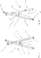
- the endless pantograph comprises two sets of linear sub-pantographs.
- the first set of linear sub-pantographs includes three or more linear sub-pantographs that define the edges of a polygon in the undeployed and deployed states.
- the second set of linear sub-pantographs comprises the same number of linear sub-pantographs as the first set of linear sub-pantographs and also define the edges of a plane polygon in the undeployed and deployed states.
- the second end of each of the tapes is operatively connected to or adjacent to a feed antenna of the reflectarray antenna.
- the three tapes contribute to the positioning of the deployed endless pantograph and the deployed reflectarray relative to the feed antenna in a reflectarray antenna.
- the deployed tapes and the deployed endless pantograph substantially define a pyramidic or conic structure.
- at least two of the tapes are of different lengths.
- the deployable structure when fully deployed, establishes the reflectarray and the feed antenna in a configuration known as a reflectarray antenna with an offset feed, i.e., the boresight of the feed antenna is not parallel to a line perpendicular to the deployed reflectarray.
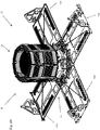
- a reflectarray antenna comprising a deployable structure 20 for use in establishing the reflectarray antenna (hereinafter referred to as "the deployable structure 20") is described.
- the deployable structure 20 conforms to a design specification which requires the deployable structure 20, in the undeployed state, to fit within a volume that is 20 cm x 20 cm x 25 cm. Additional, the deployable structure 20 is required to have a mass of no more than 4 kg. Although the deployable structure 20 conforms to the this design specification, it should be appreciated that adaptation to other form factors and mass requirements is feasible.
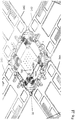
- a spring structure is located at each of multiple pivots points of the endless pantograph 52.
- the spring structure 90 is associated with a pivot structure 92 that is used to establish a center pivot point between the pair of crossing legs or links 150A, 150B of an endless pantograph.
- the pivot structure 92 includes a first hole 98A associated with cross leg 150A, a second hole 98B associated with crossing leg 150B, a nut 100, and screw 102 that extends through each of the holes and engages the nut to establish a pivot connection between the crossing legs 150A, 150B.
- the nut 100, secrew 102 and holes 98A, 98B implement a full floating axle structure.
Landscapes
- Engineering & Computer Science (AREA)
- Remote Sensing (AREA)
- Aviation & Aerospace Engineering (AREA)
- Physics & Mathematics (AREA)
- Astronomy & Astrophysics (AREA)
- General Physics & Mathematics (AREA)
- Electromagnetism (AREA)
- Life Sciences & Earth Sciences (AREA)
- Sustainable Development (AREA)
- Sustainable Energy (AREA)
- Chemical & Material Sciences (AREA)
- Combustion & Propulsion (AREA)
- Aerials With Secondary Devices (AREA)
- Details Of Aerials (AREA)
Claims (16)
- Antenne à réseau réflecteur comprenant : une structure déployable destinée à être utilisée pour établir l'antenne à réseau réflecteur, la structure déployable comprenant :une base (32) ;une antenne d'alimentation (24) destinée à être utilisée dans l'antenne à réseau réflecteur ;un élément électrique flexible (26) destiné à être utilisé dans l'antenne à réseau réflecteur ;dans laquelle l'élément électrique flexible (26) est plié dans un état non déployé ;dans laquelle l'élément électrique flexible (26) est déplié dans un état déployé par rapport à l'état non déployé ; etun mécanisme de déploiement (28) pour faire effectuer une transition à l'élément électrique flexible (26) de l'état non déployé à l'état déployé ;dans lequel le mécanisme de déploiement (28) comprendune structure sans fin (52) formant une boucle fermée, définissant un périmètre qui a une première longueur à l'état non déployé et une deuxième longueur qui est supérieure à la première longueur lorsque la structure sans fin effectue une transition de l'état non déployé à l'état déployé ; et mise opérationnellement en prise avec l'élément électrique flexible (26) ; etun dispositif d'alimentation d'énergie (90) destiné à être utilisé pour faire effectuer une transition à la structure sans fin de l'état non déployé à l'état déployé ;dans laquelle, lorsque la structure sans fin effectue la transition de l'état non déployé à l'état déployé, l'élément électrique flexible (26) est configuré pour effectuer une transition de la condition pliée à l'état non déployé à la condition dépliée ;dans laquelle :la structure sans fin est une structure de pantographe sans fin ;le mécanisme de déploiement (28) comprend une pluralité de bandes (132A-132D) avec chaque bande qui a une première extrémité qui est raccordée, de manière opérationnelle, à la base et une seconde extrémité qui est raccordée, de manière opérationnelle, à la structure de pantographe sans fin ;dans laquelle chaque bande de la pluralité de bandes (132A-132D) est adaptée pour effectuer une transition d'un état non déployé dans lequel la structure de pantographe sans fin est positionnée dans une première position par rapport à la base, à un état déployé dans lequel la structure de pantographe sans fin est positionnée dans une seconde position par rapport à la base, qui est à une plus grande distance de la base que la première position ;et dans laquelle l'élément électrique flexible (26) comprend une membrane de réseau réflecteur à deux couches supportant un réseau d'éléments rayonnants.
- Antenne à réseau réflecteur selon la revendication 1, dans laquelle la structure de pantographe sans fin comprend un premier pantographe (76A) et un second pantographe (76B) qui est raccordé, de manière pivotante, au premier pantographe autour d'un axe dans le plan de la membrane déployée de réseau réflecteur à deux couches.
- Antenne à réseau réflecteur selon la revendication 1, dans laquelle la structure de pantographe sans fin a une forme polygonale avec au moins des premier, deuxième et troisième côtés (78A-78C), la structure comprenant une structure de sommet (82) entre chaque paire de côtés, et un connecteur (120) pour raccorder la membrane de réseau réflecteur à deux couches (26) à la structure de sommet.
- Antenne à réseau réflecteur selon la revendication 1, comprenant en outre :
un limiteur (152) pour limiter l'étendue sur laquelle la structure de pantographe sans fin peut être déployée. - Antenne à réseau réflecteur selon la revendication 1, comprenant en outre :
une pluralité de limiteurs (152, 152), chaque limiteur étant opérationnellement raccordé à une première patte de la structure de pantographe sans fin et étant adapté pour mettre en prise une seconde patte de la structure de pantographe sans fin qui est raccordée, de manière pivotante, à la première patte lorsque la rotation relative des première et seconde pattes établit un angle prédéterminé entre les première et seconde pattes et empêche la rotation supplémentaire des première et seconde pattes l'une par rapport à l'autre. - Antenne à réseau réflecteur selon la revendication 5, dans laquelle le dispositif d'alimentation d'énergie comprend un ressort (104) qui met en prise, de manière opérationnelle, les première et seconde pattes de la structure de pantographe sans fin, le ressort stockant une première quantité d'énergie potentielle à l'état non déployé, et une seconde quantité d'énergie potentielle qui est inférieure à la première quantité d'énergie potentielle lorsque la structure de pantographe sans fin effectue une transition de l'état non déployé à l'état déployé.
- Antenne à réseau réflecteur selon la revendication 5 ou 6, dans lequel le dispositif d'alimentation d'énergie comprend une pluralité de ressorts (104), dans laquelle chaque ressort de la pluralité de ressorts met en prise, de manière opérationnelle, une paire différente de pattes de la structure de pantographe sans fin.
- Antenne à réseau réflecteur selon la revendication 1, dans laquelle le dispositif d'alimentation d'énergie comprend une pluralité de moteurs électriques (130A-130D) avec chaque moteur de la pluralité de moteurs qui met en prise de manière opérationnelle une bande de la pluralité de bandes, de sorte que chaque bande de la pluralité de bandes est mise en prise par un moteur de la pluralité de moteurs.
- Antenne à réseau réflecteur selon la revendication 1, dans laquelle une première bande de la pluralité de bandes a une première longueur déployée et une deuxième bande de la pluralité de bandes a une deuxième longueur déployée pour faciliter l'établissement d'une relation positionnelle d'alimentation décalée entre l'antenne d'alimentation et l'élément électrique flexible, lorsque l'élément électrique flexible est à l'état déployé.
- Antenne à réseau réflecteur selon l'une quelconque des revendications précédentes, dans laquelle :
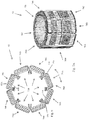
la structure de pantographe sans fin a huit sommets et quatre bandes. - Antenne à réseau réflecteur selon la revendication 1, dans laquelle chaque bande de la pluralité de bandes a une partie sensible disposée dans un rouleau à l'état non déployé et une partie sensible de la bande est disposée d'une manière linéaire à l'état déployé.
- Antenne à réseau réflecteur selon la revendication 9, dans laquelle :une troisième bande de la pluralité de bandes a une troisième longueur déployée ;dans laquelle la troisième longueur est différente des première et deuxième longueurs déployées des première et deuxième bandes.
- Antenne à réseau réflecteur selon la revendication 1, comprenant en outre :une cassette à bande (130A) pour stocker une partie sensible d'une bande dans un rouleau disposé autour d'un axe de bande lorsque la bande est dans un état non déployé et une structure de pivot (180) qui raccorde, de manière opérationnelle, la cassette à bande à la base ;dans laquelle la structure de pivot permet à la cassette à bande de tourner autour de l'axe de bande et est sollicitée pour permettre à la cassette à bande de tourner autour d'un axe transversal qui est sensiblement perpendiculaire à l'axe de bande.
- Antenne à réseau réflecteur selon la revendication 13, dans laquelle la structure de pivot comprend une paire de charnières en serpentin (182A, 182B).
- Antenne à réseau réflecteur selon la revendication 1, dans laquelle :la base est raccordée, de manière opérationnelle, à la pluralité de bandes et est adaptée pour se raccorder à une structure de satellite afin de raccorder, de manière opérationnelle, la base, le mécanisme de déploiement et l'élément électrique flexible à la structure de satellite ;dans laquelle, lorsque l'élément électrique flexible est à l'état déployé, la pluralité de bandes sont structurellement positionnées entre l'élément électrique flexible et la base.
- Antenne à réseau réflecteur selon l'une quelconque des revendications précédentes, dans laquelle :
au moins une bande de la pluralité de bandes est une bande stable quasiment double.
Applications Claiming Priority (2)
| Application Number | Priority Date | Filing Date | Title |
|---|---|---|---|
| US201562233115P | 2015-09-25 | 2015-09-25 | |
| PCT/US2016/053844 WO2017054005A1 (fr) | 2015-09-25 | 2016-09-26 | Structure déployable destinée à être utilisée dans l'établissement d'une antenne à réseau réflecteur |
Publications (3)
| Publication Number | Publication Date |
|---|---|
| EP3353855A1 EP3353855A1 (fr) | 2018-08-01 |
| EP3353855A4 EP3353855A4 (fr) | 2019-05-01 |
| EP3353855B1 true EP3353855B1 (fr) | 2021-07-07 |
Family
ID=58387542
Family Applications (1)
| Application Number | Title | Priority Date | Filing Date |
|---|---|---|---|
| EP16849901.0A Active EP3353855B1 (fr) | 2015-09-25 | 2016-09-26 | Structure déployable destinée à être utilisée dans l'établissement d'une antenne à réseau réflecteur |
Country Status (6)
| Country | Link |
|---|---|
| US (3) | US10283835B2 (fr) |
| EP (1) | EP3353855B1 (fr) |
| CA (1) | CA2999987C (fr) |
| IL (2) | IL284760B2 (fr) |
| SG (1) | SG10202103957UA (fr) |
| WO (1) | WO2017054005A1 (fr) |
Cited By (1)
| Publication number | Priority date | Publication date | Assignee | Title |
|---|---|---|---|---|
| EP4430347A4 (fr) * | 2021-11-12 | 2025-09-17 | Lgarde Inc | Concentrateur solaire déployable léger à faible volume de stockage pour applications spatiales |
Families Citing this family (30)
| Publication number | Priority date | Publication date | Assignee | Title |
|---|---|---|---|---|
| US10773833B1 (en) | 2011-08-30 | 2020-09-15 | MMA Design, LLC | Panel for use in a deployable and cantilevered solar array structure |
| US10263316B2 (en) * | 2013-09-06 | 2019-04-16 | MMA Design, LLC | Deployable reflectarray antenna structure |
| US10170843B2 (en) | 2015-05-29 | 2019-01-01 | California Institute Of Technology | Parabolic deployable antenna |
| US20170110803A1 (en) * | 2015-07-08 | 2017-04-20 | California Institute Of Technology | Deployable reflectarray high gain antenna for satellite applications |
| EP3353855B1 (fr) | 2015-09-25 | 2021-07-07 | MMA Design, LLC | Structure déployable destinée à être utilisée dans l'établissement d'une antenne à réseau réflecteur |
| CN107978837B (zh) * | 2017-12-21 | 2023-11-17 | 星际漫步(北京)航天科技有限公司 | 充气式柔性天线及其展开方法 |
| CN108649313B (zh) * | 2017-12-27 | 2020-01-31 | 哈尔滨工业大学(深圳) | 一种基于刚柔混用剪叉机构的可展开曲面桁架机构 |
| FR3081083B1 (fr) * | 2018-05-08 | 2024-11-29 | Macdonald Dettwiler & Associates Corp | Réflecteur d'antenne à réseau de réflexion à ouverture déployable et léger |
| CN109080853A (zh) * | 2018-07-20 | 2018-12-25 | 广西大学 | 一种基于菱形单元仿蜘蛛网空间可展机构 |
| CN109050979B (zh) * | 2018-07-20 | 2021-08-17 | 广西大学 | 一种剪式折展单元刚性铰链连接大空间可展机构 |
| EP3912224A4 (fr) * | 2019-01-18 | 2022-10-05 | M.M.A. Design, LLC | Système déployable à membrane souple |
| US11942687B2 (en) * | 2019-02-25 | 2024-03-26 | Eagle Technology, Llc | Deployable reflectors |
| CN110828965A (zh) * | 2019-09-30 | 2020-02-21 | 中国空间技术研究院 | 一种基于轮式同步转动机构锥式环形桁架可展开天线结构 |
| CN110970701A (zh) * | 2019-09-30 | 2020-04-07 | 中国空间技术研究院 | 一种扭簧驱动的锥式单层环形桁架可展开天线机构 |
| CN111146557B (zh) * | 2019-12-14 | 2022-03-15 | 中国电子科技集团公司第三十九研究所 | 一种轻质柔性充气可展开偶极子天线结构 |
| EP3838353A1 (fr) * | 2019-12-20 | 2021-06-23 | Maike Weinast | Trampoline pliable, procédé de pliage d'un trampoline et procédé permettant de tendre une toile de rebond |
| EP3851386B1 (fr) * | 2020-01-15 | 2023-03-08 | Airbus Defence and Space Limited | Appareil d'assemblage |
| US11223111B2 (en) | 2020-06-11 | 2022-01-11 | Eagle Technology, Llc | Systems and methods for providing antennas with mechanically coupled offset positions |
| CA3189429A1 (fr) | 2020-08-14 | 2022-02-17 | Mark Allen BAILEY | Systeme de surface d'orientation de rayonnement electromagnetique deployable avec actionneurs |
| WO2022036279A1 (fr) * | 2020-08-14 | 2022-02-17 | M.M.A. Design, LLC | Système de lentille d'orientation de rayonnement électromagnétique déployable |
| EP4197061A4 (fr) * | 2020-08-14 | 2024-09-18 | M.M.A. Design, LLC | Système de lentille d'orientation de rayonnement électromagnétique déployable |
| CN112599185B (zh) * | 2020-09-21 | 2022-04-12 | 北京交通大学 | 一种双模式缩放机构 |
| KR102435720B1 (ko) * | 2020-10-14 | 2022-08-25 | 연세대학교 산학협력단 | 위성용 구조막 전개장치 |
| CN112531315B (zh) * | 2020-11-27 | 2021-11-30 | 浙江大学 | 一种星载相控阵天线同步展开机构 |
| US11411318B2 (en) | 2020-12-08 | 2022-08-09 | Eagle Technology, Llc | Satellite antenna having pantographic trusses and associated methods |
| CN112591142B (zh) * | 2020-12-14 | 2022-11-08 | 兰州空间技术物理研究所 | 一种适用于柔性航天器的收纳装置 |
| CA3226553A1 (fr) * | 2021-08-04 | 2023-02-09 | M.M.A. Design, LLC | Antenne deployable multi-direction |
| CN115954643A (zh) * | 2023-01-13 | 2023-04-11 | 中国空间技术研究院 | 一种可展桁架式薄膜反射阵列天线 |
| CN116315572A (zh) * | 2023-04-04 | 2023-06-23 | 上海宇航系统工程研究所 | 一种超大型平面天线二维展开机构 |
| US12595080B1 (en) * | 2024-11-21 | 2026-04-07 | Nanjing University Of Aeronautics And Astronautics | On-orbit assembly auxiliary device for space structures |
Family Cites Families (84)
| Publication number | Priority date | Publication date | Assignee | Title |
|---|---|---|---|---|
| US3010372A (en) | 1960-02-11 | 1961-11-28 | Wade E Lanford | Folding apparatus |
| US3710806A (en) | 1971-10-27 | 1973-01-16 | V Kelly | Erectable building structure |
| US4133501A (en) | 1975-09-30 | 1979-01-09 | Communications Satellite Corporation | Self-deployable solar cell panel |
| US4375878A (en) | 1980-10-28 | 1983-03-08 | Lockheed Missiles & Space Company, Inc. | Space satellite with agile payload orientation system |
| US4380013A (en) * | 1981-02-17 | 1983-04-12 | General Dynamics Corp./Convair Division | Expandable panel and truss system/antenna/solar panel |
| US4419828A (en) | 1981-05-19 | 1983-12-13 | Farris David L | Apparatus for establishing the junction contour for intersecting pipes |
| US4475323A (en) * | 1982-04-30 | 1984-10-09 | Martin Marietta Corporation | Box truss hoop |
| IT1162948B (it) | 1983-09-30 | 1987-04-01 | Aeritalia Spa | Braccio estensibile particolarmente per veicoli o moduli spaziali |
| US5040907A (en) | 1990-02-13 | 1991-08-20 | Aec-Able Engineering Co. | Bearing system with redundancy of races |
| US5228644A (en) | 1991-05-28 | 1993-07-20 | The United States Of America As Represented By The United States National Aeronautics And Space Administration | Solar powered system for a space vehicle |
| US5189773A (en) | 1991-07-15 | 1993-03-02 | Aec-Able Engineering Co., Inc. | Mast forming and deployment system |
| US5218375A (en) * | 1991-11-15 | 1993-06-08 | Antenna Products Corporation | Rapidly extendible and retractable antenna mast |
| US5296044A (en) | 1992-03-06 | 1994-03-22 | Aec-Able Engineering Company, Inc. | Lightweight stowable and deployable solar cell array |
| US5298085A (en) | 1992-03-24 | 1994-03-29 | Aec-Able Engineering Company, Inc. | Support blanket for solar cell arrays |
| US5365241A (en) | 1992-06-24 | 1994-11-15 | Williams Lawrence I S | Method and apparatus for performing planar near-field antenna measurement using bi-polar geometry |
| US5680145A (en) * | 1994-03-16 | 1997-10-21 | Astro Aerospace Corporation | Light-weight reflector for concentrating radiation |
| US5520747A (en) | 1994-05-02 | 1996-05-28 | Astro Aerospace Corporation | Foldable low concentration solar array |
| US6470902B1 (en) | 1994-07-25 | 2002-10-29 | United California Bank | Erectable canopy with reinforced roof structure |
| US5511572A (en) | 1994-07-25 | 1996-04-30 | Carter; Mark C. | Collapsible shelter with flexible, collapsible canopy |
| US6041800A (en) | 1998-08-07 | 2000-03-28 | Carter; Mark C. | Erectable shelter with gable roof |
| US5644322A (en) | 1995-06-16 | 1997-07-01 | Space Systems/Loral, Inc. | Spacecraft antenna reflectors and stowage and restraint system therefor |
| US5785280A (en) | 1995-07-20 | 1998-07-28 | Space Systems/Loral, Inc. | Hybrid solar panel array |
| US5701923A (en) | 1996-03-07 | 1997-12-30 | Losi, Jr.; Raymond | Collapsible shelter |
| GB9606200D0 (en) | 1996-03-25 | 1996-05-29 | Daton Lovett Andrew J | An extendible member |
| US5864324A (en) * | 1996-05-15 | 1999-01-26 | Trw Inc. | Telescoping deployable antenna reflector and method of deployment |
| US6081234A (en) | 1997-07-11 | 2000-06-27 | California Institute Of Technology | Beam scanning reflectarray antenna with circular polarization |
| US6017002A (en) | 1997-07-21 | 2000-01-25 | Hughes Electronics Corporation | Thin-film solar reflectors deployable from an edge-stowed configuration |
| GB2330007B (en) * | 1997-10-03 | 2002-01-23 | Matra Marconi Space Uk Ltd | Expandable support ring |
| FR2777118B1 (fr) * | 1998-04-03 | 2000-06-02 | Aerospatiale | Reflecteur d'antenne elastiquement deformable pour engin spatial |
| US6104358A (en) | 1998-05-12 | 2000-08-15 | Trw Inc. | Low cost deployable reflector |
| US6010096A (en) | 1998-07-22 | 2000-01-04 | Space Systems/Loral, Inc. | Deployment restraint and sequencing device |
| US6147294A (en) | 1999-04-06 | 2000-11-14 | Trw Inc. | D-wing deployable solar array |
| US6323827B1 (en) | 2000-01-07 | 2001-11-27 | Trw Inc. | Micro fold reflector |
| US6419175B1 (en) | 2001-02-08 | 2002-07-16 | Vulcan Spring & Manufacturing Company | Retractor having a swivel attachment component |
| US6384787B1 (en) | 2001-02-21 | 2002-05-07 | The Boeing Company | Flat reflectarray antenna |
| GEP20053604B (en) * | 2001-06-12 | 2005-08-25 | Space Deployable Antenna Reflector | |
| US6581883B2 (en) | 2001-07-13 | 2003-06-24 | The Boeing Company | Extendable/retractable bi-fold solar array |
| WO2004076778A2 (fr) | 2003-02-21 | 2004-09-10 | Variflex, Inc. | Abri portable a roulements a rouleaux |
| US7030824B1 (en) | 2003-05-29 | 2006-04-18 | Lockheed Martin Corporation | MEMS reflectarray antenna for satellite applications |
| US6983914B2 (en) | 2004-02-12 | 2006-01-10 | The Boeing Company | Deployable solar array assembly |
| US6970143B2 (en) | 2004-03-16 | 2005-11-29 | Harris Corporation | Highly compact, precision lightweight deployable truss which accommodates side mounted components |
| US7602349B2 (en) | 2006-02-24 | 2009-10-13 | Lockheed Martin Corporation | System of stowing and deploying multiple phased arrays or combinations of arrays and reflectors |
| US7762500B1 (en) * | 2006-11-06 | 2010-07-27 | Sanjay Dhall | Telescopic wing with articulated structural spar |
| US20080283670A1 (en) | 2006-12-13 | 2008-11-20 | Thomas Jeffrey Harvey | K-truss deployable boom system |
| JP5036417B2 (ja) * | 2007-06-18 | 2012-09-26 | 株式会社越智工業所 | 蛇腹式フレームを用いた構造体 |
| US9214892B2 (en) | 2007-11-21 | 2015-12-15 | Orbital Atk, Inc. | Solar arrays |
| US8291781B2 (en) | 2007-12-21 | 2012-10-23 | Schlumberger Technology Corporation | System and methods for actuating reversibly expandable structures |
| US8356774B1 (en) | 2008-04-21 | 2013-01-22 | The United States Of America As Represented By The Secretary Of The Air Force | Structure for storing and unfurling a flexible material |
| FR2933771B1 (fr) * | 2008-07-11 | 2010-08-13 | Thales Sa | Metre ruban a deploiement thermique et structure deployable comportant ledit metre ruban |
| JP5276952B2 (ja) * | 2008-11-05 | 2013-08-28 | サカセ・アドテック株式会社 | 伸展構造物 |
| US10370126B1 (en) | 2009-09-09 | 2019-08-06 | M.M.A. Design, LLC | Solar panel array assembly |
| US8757554B1 (en) | 2009-09-09 | 2014-06-24 | MMA Design, LLC | Deployable and tracked solar array mechanism for nano-satellites |
| US8905357B1 (en) * | 2009-10-02 | 2014-12-09 | MMA Design, LLC | Thin membrane structure |
| US8289221B1 (en) | 2010-06-28 | 2012-10-16 | The United States Of America As Represented By The Secretary Of The Air Force | Deployable reflectarray antenna system |
| US8814099B1 (en) | 2010-08-31 | 2014-08-26 | MMA Design, LLC | Deployable morphing modular solar array |
| US9550584B1 (en) | 2010-09-30 | 2017-01-24 | MMA Design, LLC | Deployable thin membrane apparatus |
| KR20120104855A (ko) | 2011-03-14 | 2012-09-24 | 한국전자통신연구원 | 전개형 반사 배열 안테나 |
| US8816187B1 (en) | 2011-04-18 | 2014-08-26 | The Boeing Company | Stowing or deploying a solar array |
| US8720830B1 (en) | 2012-01-30 | 2014-05-13 | United Launch Alliance, L.L.C. | Efficient solar panel wing-stowage on a space launch vehicle |
| ES2635414T3 (es) | 2012-03-15 | 2017-10-03 | European Space Agency | Estructura anular de soporte mecánico |
| US9840060B2 (en) | 2012-11-21 | 2017-12-12 | Tendeg Llc | Rigid slit-tube laminate system |
| US9528264B2 (en) | 2013-02-15 | 2016-12-27 | Tendeg Llc | Collapsible roll-out truss |
| US9637248B2 (en) * | 2013-03-15 | 2017-05-02 | The Boeing Company | Component deployment system |
| US9270021B1 (en) | 2013-09-06 | 2016-02-23 | M.M.A. Design, LLC | Low-profile mast array |
| US10263316B2 (en) | 2013-09-06 | 2019-04-16 | MMA Design, LLC | Deployable reflectarray antenna structure |
| US9593485B2 (en) | 2014-03-12 | 2017-03-14 | Roccor, Llc | Deployment system for supported retractable extension of a composite boom |
| EP3059800B1 (fr) | 2015-02-17 | 2017-11-08 | MMA Design, LLC | Structure d'antenne réseau à réflexion déployable |
| US10170843B2 (en) | 2015-05-29 | 2019-01-01 | California Institute Of Technology | Parabolic deployable antenna |
| US10119292B1 (en) | 2015-07-02 | 2018-11-06 | M.M.A. Design, LLC | Deployable boom and deployable boom with solar blanket |
| US20170110803A1 (en) | 2015-07-08 | 2017-04-20 | California Institute Of Technology | Deployable reflectarray high gain antenna for satellite applications |
| US10211535B2 (en) | 2015-07-20 | 2019-02-19 | The Regents Of The University Of California | Low-profile circularly-polarized single-probe broadband antenna |
| EP3353855B1 (fr) | 2015-09-25 | 2021-07-07 | MMA Design, LLC | Structure déployable destinée à être utilisée dans l'établissement d'une antenne à réseau réflecteur |
| US11228115B2 (en) | 2016-01-11 | 2022-01-18 | Tethers Unlimited Inc. | Methods and apparatus for manufacture and in-space assembly of antennas |
| US10256530B2 (en) | 2016-01-28 | 2019-04-09 | Tendeg Llc | Deployable reflector |
| US10418721B2 (en) | 2016-03-29 | 2019-09-17 | California Institute Of Technology | Low-profile and high-gain modulated metasurface antennas from gigahertz to terahertz range frequencies |
| WO2018005532A1 (fr) | 2016-06-27 | 2018-01-04 | The Regents Of The University Of California | Réseaux d'antennes redresseuses unipolaires réparties sur une surface courbe pour collecte d'énergie rf ambiante multidirectionnelle, multipolarisation et multibande |
| WO2018089530A1 (fr) | 2016-11-08 | 2018-05-17 | River Front Services, Inc. | Support déployable |
| US10276926B2 (en) | 2017-01-06 | 2019-04-30 | California Institute Of Technology | Deployable reflectarray antenna |
| US11009695B2 (en) | 2017-01-17 | 2021-05-18 | Tendeg Llc | Occulter petal unfurling system |
| WO2018157061A1 (fr) | 2017-02-27 | 2018-08-30 | River Front Services, Inc. | Appareil de déploiement de bande structurale |
| WO2018191427A1 (fr) | 2017-04-11 | 2018-10-18 | River Front Services, Inc. | Plate-forme d'espace extensible |
| US20180297724A1 (en) | 2017-04-11 | 2018-10-18 | River Front Services, Inc. | Extensible space platform |
| EP3673227B1 (fr) | 2017-08-24 | 2021-06-23 | River Front Services, Inc. | Système détonant explosif et composants |
| GB2571740A (en) | 2018-03-07 | 2019-09-11 | Oxford Space Systems Ltd | Deployable spacecraft body |
-
2016
- 2016-09-26 EP EP16849901.0A patent/EP3353855B1/fr active Active
- 2016-09-26 CA CA2999987A patent/CA2999987C/fr active Active
- 2016-09-26 SG SG10202103957UA patent/SG10202103957UA/en unknown
- 2016-09-26 WO PCT/US2016/053844 patent/WO2017054005A1/fr not_active Ceased
- 2016-09-26 US US15/276,725 patent/US10283835B2/en active Active
- 2016-09-26 IL IL284760A patent/IL284760B2/en unknown
-
2018
- 2018-03-22 IL IL258315A patent/IL258315B/en unknown
-
2019
- 2019-03-07 US US16/295,615 patent/US10971793B2/en active Active
-
2021
- 2021-02-08 US US17/170,353 patent/US11677133B2/en active Active
Non-Patent Citations (1)
| Title |
|---|
| None * |
Cited By (1)
| Publication number | Priority date | Publication date | Assignee | Title |
|---|---|---|---|---|
| EP4430347A4 (fr) * | 2021-11-12 | 2025-09-17 | Lgarde Inc | Concentrateur solaire déployable léger à faible volume de stockage pour applications spatiales |
Also Published As
| Publication number | Publication date |
|---|---|
| US20210184331A1 (en) | 2021-06-17 |
| US10971793B2 (en) | 2021-04-06 |
| IL284760B1 (en) | 2023-06-01 |
| IL258315A (en) | 2018-05-31 |
| SG10202103957UA (en) | 2021-05-28 |
| US10283835B2 (en) | 2019-05-07 |
| IL258315B (en) | 2021-08-31 |
| IL284760A (en) | 2021-08-31 |
| EP3353855A1 (fr) | 2018-08-01 |
| CA2999987A1 (fr) | 2017-03-30 |
| CA2999987C (fr) | 2023-09-05 |
| IL284760B2 (en) | 2023-10-01 |
| US20190207291A1 (en) | 2019-07-04 |
| US11677133B2 (en) | 2023-06-13 |
| EP3353855A4 (fr) | 2019-05-01 |
| US20170093046A1 (en) | 2017-03-30 |
| WO2017054005A1 (fr) | 2017-03-30 |
Similar Documents
| Publication | Publication Date | Title |
|---|---|---|
| US11677133B2 (en) | Deployable structure for use in establishing a reflectarray antenna | |
| US11901605B2 (en) | Deployable antenna structure | |
| US9496621B2 (en) | Large deployable reflector for a satellite antenna | |
| EP1987604B1 (fr) | Système d'arrimage et de déploiement de multiples antennes réseau à commande de phase ou combinaison d'antennes réseau à commande de phase et de réflecteurs | |
| EP3059800B1 (fr) | Structure d'antenne réseau à réflexion déployable | |
| US10418712B1 (en) | Folded optics mesh hoop column deployable reflector system | |
| US3576566A (en) | Closed loop antenna reflector supporting structure | |
| JP4876941B2 (ja) | 展開型アンテナ | |
| EP3654452B1 (fr) | Réflecteur d'antenne à maillage à périmètre déployable | |
| US20060071872A1 (en) | Ground based inflatable antenna | |
| US20180151938A1 (en) | Easyly deployable phased antenna for a spacecraft and system of such antennas | |
| EP3761443B1 (fr) | Antenne ayant des ailettes d'antenne déployables et procédés associés | |
| US6888513B1 (en) | Method and apparatus for storage and deployment of folded panel structures | |
| US3495250A (en) | Expandable cavity-backed spiral antenna | |
| US7151509B2 (en) | Apparatus for use in providing wireless communication and method for use and deployment of such apparatus | |
| KR20260012412A (ko) | 전개형 래핑 립 안테나를 위한 사선 회전축 자동 잠금 힌지 장치 및 그의 제조 방법 | |
| Castro et al. | Design and Build Process of a Small Satellite Deployable UHF Antenna | |
| WO2026069081A1 (fr) | Antenne spatiale déployable avec réseau réflecteur enroulable et/ou pliable en z |
Legal Events
| Date | Code | Title | Description |
|---|---|---|---|
| STAA | Information on the status of an ep patent application or granted ep patent |
Free format text: STATUS: THE INTERNATIONAL PUBLICATION HAS BEEN MADE |
|
| PUAI | Public reference made under article 153(3) epc to a published international application that has entered the european phase |
Free format text: ORIGINAL CODE: 0009012 |
|
| STAA | Information on the status of an ep patent application or granted ep patent |
Free format text: STATUS: REQUEST FOR EXAMINATION WAS MADE |
|
| 17P | Request for examination filed |
Effective date: 20180425 |
|
| AK | Designated contracting states |
Kind code of ref document: A1 Designated state(s): AL AT BE BG CH CY CZ DE DK EE ES FI FR GB GR HR HU IE IS IT LI LT LU LV MC MK MT NL NO PL PT RO RS SE SI SK SM TR |
|
| AX | Request for extension of the european patent |
Extension state: BA ME |
|
| RAP1 | Party data changed (applicant data changed or rights of an application transferred) |
Owner name: MMA DESIGN, LLC |
|
| RIN1 | Information on inventor provided before grant (corrected) |
Inventor name: HARVEY, THOMAS J. Inventor name: STAMM, SHANE E. Inventor name: PELZMANN, CHRISTOPHER A. Inventor name: BAILEY, MARK A. Inventor name: HARVEY, TOBY J. Inventor name: WIENS, MITCHELL T. |
|
| RIN1 | Information on inventor provided before grant (corrected) |
Inventor name: HARVEY, TOBY J. Inventor name: STAMM, SHANE E. Inventor name: PELZMANN, CHRISTOPHER A. Inventor name: BAILEY, MARK A. Inventor name: WIENS, MITCHELL T. Inventor name: HARVEY, THOMAS J. |
|
| RIN1 | Information on inventor provided before grant (corrected) |
Inventor name: WIENS, MITCHELL T. Inventor name: HARVEY, TOBY J. Inventor name: STAMM, SHANE E. Inventor name: HARVEY, THOMAS J. Inventor name: BAILEY, MARK A. Inventor name: PELZMANN, CHRISTOPHER A. |
|
| DAV | Request for validation of the european patent (deleted) | ||
| DAX | Request for extension of the european patent (deleted) | ||
| RIC1 | Information provided on ipc code assigned before grant |
Ipc: H01Q 1/28 20060101AFI20170411BHEP Ipc: F24J 2/52 20060101ALI20170411BHEP Ipc: H01Q 15/16 20060101ALI20170411BHEP |
|
| A4 | Supplementary search report drawn up and despatched |
Effective date: 20190403 |
|
| RIC1 | Information provided on ipc code assigned before grant |
Ipc: B64G 1/22 20060101ALI20190328BHEP Ipc: H01Q 1/08 20060101ALI20190328BHEP Ipc: H01Q 1/12 20060101ALN20190328BHEP Ipc: H01Q 3/46 20060101ALI20190328BHEP Ipc: H01Q 1/28 20060101ALI20190328BHEP Ipc: B64G 1/44 20060101ALN20190328BHEP Ipc: H01Q 15/16 20060101AFI20190328BHEP Ipc: B64G 1/66 20060101ALI20190328BHEP Ipc: H01Q 15/14 20060101ALN20190328BHEP Ipc: B64G 1/40 20060101ALN20190328BHEP |
|
| STAA | Information on the status of an ep patent application or granted ep patent |
Free format text: STATUS: EXAMINATION IS IN PROGRESS |
|
| 17Q | First examination report despatched |
Effective date: 20200310 |
|
| RIC1 | Information provided on ipc code assigned before grant |
Ipc: H01Q 1/28 20060101ALI20200730BHEP Ipc: H01Q 15/14 20060101ALN20200730BHEP Ipc: B64G 1/40 20060101ALN20200730BHEP Ipc: H01Q 1/12 20060101ALN20200730BHEP Ipc: B64G 1/44 20060101ALN20200730BHEP Ipc: B64G 1/22 20060101ALI20200730BHEP Ipc: H01Q 15/16 20060101AFI20200730BHEP Ipc: H01Q 3/46 20060101ALI20200730BHEP Ipc: B64G 1/66 20060101ALI20200730BHEP Ipc: H01Q 1/08 20060101ALI20200730BHEP |
|
| GRAP | Despatch of communication of intention to grant a patent |
Free format text: ORIGINAL CODE: EPIDOSNIGR1 |
|
| STAA | Information on the status of an ep patent application or granted ep patent |
Free format text: STATUS: GRANT OF PATENT IS INTENDED |
|
| INTG | Intention to grant announced |
Effective date: 20201016 |
|
| RIC1 | Information provided on ipc code assigned before grant |
Ipc: H01Q 1/08 20060101ALI20201002BHEP Ipc: H01Q 1/12 20060101ALN20201002BHEP Ipc: B64G 1/66 20060101ALI20201002BHEP Ipc: H01Q 15/14 20060101ALN20201002BHEP Ipc: H01Q 3/46 20060101ALI20201002BHEP Ipc: B64G 1/40 20060101ALN20201002BHEP Ipc: H01Q 1/28 20060101ALI20201002BHEP Ipc: B64G 1/44 20060101ALN20201002BHEP Ipc: B64G 1/22 20060101ALI20201002BHEP Ipc: H01Q 15/16 20060101AFI20201002BHEP |
|
| GRAJ | Information related to disapproval of communication of intention to grant by the applicant or resumption of examination proceedings by the epo deleted |
Free format text: ORIGINAL CODE: EPIDOSDIGR1 |
|
| STAA | Information on the status of an ep patent application or granted ep patent |
Free format text: STATUS: EXAMINATION IS IN PROGRESS |
|
| REG | Reference to a national code |
Ref country code: DE Ref legal event code: R079 Ref document number: 602016060428 Country of ref document: DE Free format text: PREVIOUS MAIN CLASS: H01Q0001280000 Ipc: H01Q0015160000 |
|
| INTC | Intention to grant announced (deleted) | ||
| GRAP | Despatch of communication of intention to grant a patent |
Free format text: ORIGINAL CODE: EPIDOSNIGR1 |
|
| STAA | Information on the status of an ep patent application or granted ep patent |
Free format text: STATUS: GRANT OF PATENT IS INTENDED |
|
| RIC1 | Information provided on ipc code assigned before grant |
Ipc: H01Q 1/08 20060101ALI20210127BHEP Ipc: H01Q 15/14 20060101ALN20210127BHEP Ipc: B64G 1/22 20060101ALI20210127BHEP Ipc: H01Q 15/16 20060101AFI20210127BHEP Ipc: B64G 1/44 20060101ALN20210127BHEP Ipc: B64G 1/66 20060101ALI20210127BHEP Ipc: H01Q 3/46 20060101ALI20210127BHEP Ipc: H01Q 1/28 20060101ALI20210127BHEP Ipc: B64G 1/40 20060101ALN20210127BHEP Ipc: H01Q 1/12 20060101ALN20210127BHEP |
|
| INTG | Intention to grant announced |
Effective date: 20210219 |
|
| GRAS | Grant fee paid |
Free format text: ORIGINAL CODE: EPIDOSNIGR3 |
|
| GRAA | (expected) grant |
Free format text: ORIGINAL CODE: 0009210 |
|
| STAA | Information on the status of an ep patent application or granted ep patent |
Free format text: STATUS: THE PATENT HAS BEEN GRANTED |
|
| AK | Designated contracting states |
Kind code of ref document: B1 Designated state(s): AL AT BE BG CH CY CZ DE DK EE ES FI FR GB GR HR HU IE IS IT LI LT LU LV MC MK MT NL NO PL PT RO RS SE SI SK SM TR |
|
| REG | Reference to a national code |
Ref country code: GB Ref legal event code: FG4D |
|
| REG | Reference to a national code |
Ref country code: AT Ref legal event code: REF Ref document number: 1409479 Country of ref document: AT Kind code of ref document: T Effective date: 20210715 |
|
| REG | Reference to a national code |
Ref country code: DE Ref legal event code: R096 Ref document number: 602016060428 Country of ref document: DE |
|
| REG | Reference to a national code |
Ref country code: IE Ref legal event code: FG4D |
|
| REG | Reference to a national code |
Ref country code: FI Ref legal event code: FGE |
|
| REG | Reference to a national code |
Ref country code: NO Ref legal event code: T2 Effective date: 20210707 |
|
| REG | Reference to a national code |
Ref country code: LT Ref legal event code: MG9D |
|
| REG | Reference to a national code |
Ref country code: NL Ref legal event code: MP Effective date: 20210707 |
|
| REG | Reference to a national code |
Ref country code: AT Ref legal event code: MK05 Ref document number: 1409479 Country of ref document: AT Kind code of ref document: T Effective date: 20210707 |
|
| PG25 | Lapsed in a contracting state [announced via postgrant information from national office to epo] |
Ref country code: LT Free format text: LAPSE BECAUSE OF FAILURE TO SUBMIT A TRANSLATION OF THE DESCRIPTION OR TO PAY THE FEE WITHIN THE PRESCRIBED TIME-LIMIT Effective date: 20210707 Ref country code: BG Free format text: LAPSE BECAUSE OF FAILURE TO SUBMIT A TRANSLATION OF THE DESCRIPTION OR TO PAY THE FEE WITHIN THE PRESCRIBED TIME-LIMIT Effective date: 20211007 Ref country code: AT Free format text: LAPSE BECAUSE OF FAILURE TO SUBMIT A TRANSLATION OF THE DESCRIPTION OR TO PAY THE FEE WITHIN THE PRESCRIBED TIME-LIMIT Effective date: 20210707 Ref country code: PT Free format text: LAPSE BECAUSE OF FAILURE TO SUBMIT A TRANSLATION OF THE DESCRIPTION OR TO PAY THE FEE WITHIN THE PRESCRIBED TIME-LIMIT Effective date: 20211108 Ref country code: NL Free format text: LAPSE BECAUSE OF FAILURE TO SUBMIT A TRANSLATION OF THE DESCRIPTION OR TO PAY THE FEE WITHIN THE PRESCRIBED TIME-LIMIT Effective date: 20210707 Ref country code: HR Free format text: LAPSE BECAUSE OF FAILURE TO SUBMIT A TRANSLATION OF THE DESCRIPTION OR TO PAY THE FEE WITHIN THE PRESCRIBED TIME-LIMIT Effective date: 20210707 Ref country code: ES Free format text: LAPSE BECAUSE OF FAILURE TO SUBMIT A TRANSLATION OF THE DESCRIPTION OR TO PAY THE FEE WITHIN THE PRESCRIBED TIME-LIMIT Effective date: 20210707 Ref country code: SE Free format text: LAPSE BECAUSE OF FAILURE TO SUBMIT A TRANSLATION OF THE DESCRIPTION OR TO PAY THE FEE WITHIN THE PRESCRIBED TIME-LIMIT Effective date: 20210707 Ref country code: RS Free format text: LAPSE BECAUSE OF FAILURE TO SUBMIT A TRANSLATION OF THE DESCRIPTION OR TO PAY THE FEE WITHIN THE PRESCRIBED TIME-LIMIT Effective date: 20210707 |
|
| RAP4 | Party data changed (patent owner data changed or rights of a patent transferred) |
Owner name: MMA DESIGN, LLC |
|
| PG25 | Lapsed in a contracting state [announced via postgrant information from national office to epo] |
Ref country code: PL Free format text: LAPSE BECAUSE OF FAILURE TO SUBMIT A TRANSLATION OF THE DESCRIPTION OR TO PAY THE FEE WITHIN THE PRESCRIBED TIME-LIMIT Effective date: 20210707 Ref country code: LV Free format text: LAPSE BECAUSE OF FAILURE TO SUBMIT A TRANSLATION OF THE DESCRIPTION OR TO PAY THE FEE WITHIN THE PRESCRIBED TIME-LIMIT Effective date: 20210707 Ref country code: GR Free format text: LAPSE BECAUSE OF FAILURE TO SUBMIT A TRANSLATION OF THE DESCRIPTION OR TO PAY THE FEE WITHIN THE PRESCRIBED TIME-LIMIT Effective date: 20211008 |
|
| REG | Reference to a national code |
Ref country code: DE Ref legal event code: R097 Ref document number: 602016060428 Country of ref document: DE |
|
| PG25 | Lapsed in a contracting state [announced via postgrant information from national office to epo] |
Ref country code: DK Free format text: LAPSE BECAUSE OF FAILURE TO SUBMIT A TRANSLATION OF THE DESCRIPTION OR TO PAY THE FEE WITHIN THE PRESCRIBED TIME-LIMIT Effective date: 20210707 |
|
| REG | Reference to a national code |
Ref country code: CH Ref legal event code: PL |
|
| PLBE | No opposition filed within time limit |
Free format text: ORIGINAL CODE: 0009261 |
|
| STAA | Information on the status of an ep patent application or granted ep patent |
Free format text: STATUS: NO OPPOSITION FILED WITHIN TIME LIMIT |
|
| REG | Reference to a national code |
Ref country code: BE Ref legal event code: MM Effective date: 20210930 |
|
| PG25 | Lapsed in a contracting state [announced via postgrant information from national office to epo] |
Ref country code: SM Free format text: LAPSE BECAUSE OF FAILURE TO SUBMIT A TRANSLATION OF THE DESCRIPTION OR TO PAY THE FEE WITHIN THE PRESCRIBED TIME-LIMIT Effective date: 20210707 Ref country code: SK Free format text: LAPSE BECAUSE OF FAILURE TO SUBMIT A TRANSLATION OF THE DESCRIPTION OR TO PAY THE FEE WITHIN THE PRESCRIBED TIME-LIMIT Effective date: 20210707 Ref country code: RO Free format text: LAPSE BECAUSE OF FAILURE TO SUBMIT A TRANSLATION OF THE DESCRIPTION OR TO PAY THE FEE WITHIN THE PRESCRIBED TIME-LIMIT Effective date: 20210707 Ref country code: MC Free format text: LAPSE BECAUSE OF FAILURE TO SUBMIT A TRANSLATION OF THE DESCRIPTION OR TO PAY THE FEE WITHIN THE PRESCRIBED TIME-LIMIT Effective date: 20210707 Ref country code: EE Free format text: LAPSE BECAUSE OF FAILURE TO SUBMIT A TRANSLATION OF THE DESCRIPTION OR TO PAY THE FEE WITHIN THE PRESCRIBED TIME-LIMIT Effective date: 20210707 Ref country code: CZ Free format text: LAPSE BECAUSE OF FAILURE TO SUBMIT A TRANSLATION OF THE DESCRIPTION OR TO PAY THE FEE WITHIN THE PRESCRIBED TIME-LIMIT Effective date: 20210707 Ref country code: AL Free format text: LAPSE BECAUSE OF FAILURE TO SUBMIT A TRANSLATION OF THE DESCRIPTION OR TO PAY THE FEE WITHIN THE PRESCRIBED TIME-LIMIT Effective date: 20210707 |
|
| 26N | No opposition filed |
Effective date: 20220408 |
|
| PG25 | Lapsed in a contracting state [announced via postgrant information from national office to epo] |
Ref country code: LU Free format text: LAPSE BECAUSE OF NON-PAYMENT OF DUE FEES Effective date: 20210926 Ref country code: IE Free format text: LAPSE BECAUSE OF NON-PAYMENT OF DUE FEES Effective date: 20210926 Ref country code: BE Free format text: LAPSE BECAUSE OF NON-PAYMENT OF DUE FEES Effective date: 20210930 |
|
| PG25 | Lapsed in a contracting state [announced via postgrant information from national office to epo] |
Ref country code: LI Free format text: LAPSE BECAUSE OF NON-PAYMENT OF DUE FEES Effective date: 20210930 Ref country code: CH Free format text: LAPSE BECAUSE OF NON-PAYMENT OF DUE FEES Effective date: 20210930 |
|
| PG25 | Lapsed in a contracting state [announced via postgrant information from national office to epo] |
Ref country code: HU Free format text: LAPSE BECAUSE OF FAILURE TO SUBMIT A TRANSLATION OF THE DESCRIPTION OR TO PAY THE FEE WITHIN THE PRESCRIBED TIME-LIMIT; INVALID AB INITIO Effective date: 20160926 |
|
| PG25 | Lapsed in a contracting state [announced via postgrant information from national office to epo] |
Ref country code: CY Free format text: LAPSE BECAUSE OF FAILURE TO SUBMIT A TRANSLATION OF THE DESCRIPTION OR TO PAY THE FEE WITHIN THE PRESCRIBED TIME-LIMIT Effective date: 20210707 |
|
| PG25 | Lapsed in a contracting state [announced via postgrant information from national office to epo] |
Ref country code: MK Free format text: LAPSE BECAUSE OF FAILURE TO SUBMIT A TRANSLATION OF THE DESCRIPTION OR TO PAY THE FEE WITHIN THE PRESCRIBED TIME-LIMIT Effective date: 20210707 |
|
| PG25 | Lapsed in a contracting state [announced via postgrant information from national office to epo] |
Ref country code: TR Free format text: LAPSE BECAUSE OF FAILURE TO SUBMIT A TRANSLATION OF THE DESCRIPTION OR TO PAY THE FEE WITHIN THE PRESCRIBED TIME-LIMIT Effective date: 20210707 |
|
| PG25 | Lapsed in a contracting state [announced via postgrant information from national office to epo] |
Ref country code: MT Free format text: LAPSE BECAUSE OF FAILURE TO SUBMIT A TRANSLATION OF THE DESCRIPTION OR TO PAY THE FEE WITHIN THE PRESCRIBED TIME-LIMIT Effective date: 20210707 |
|
| PGFP | Annual fee paid to national office [announced via postgrant information from national office to epo] |
Ref country code: FI Payment date: 20250917 Year of fee payment: 10 |
|
| PGFP | Annual fee paid to national office [announced via postgrant information from national office to epo] |
Ref country code: DE Payment date: 20250930 Year of fee payment: 10 |
|
| PGFP | Annual fee paid to national office [announced via postgrant information from national office to epo] |
Ref country code: NO Payment date: 20250731 Year of fee payment: 10 |
|
| PGFP | Annual fee paid to national office [announced via postgrant information from national office to epo] |
Ref country code: IT Payment date: 20250903 Year of fee payment: 10 |
|
| PGFP | Annual fee paid to national office [announced via postgrant information from national office to epo] |
Ref country code: GB Payment date: 20250730 Year of fee payment: 10 |
|
| PGFP | Annual fee paid to national office [announced via postgrant information from national office to epo] |
Ref country code: FR Payment date: 20250813 Year of fee payment: 10 |