EP3353920B1 - Réseau optique passif à multiplexage par division modale - Google Patents
Réseau optique passif à multiplexage par division modale Download PDFInfo
- Publication number
- EP3353920B1 EP3353920B1 EP16770016.0A EP16770016A EP3353920B1 EP 3353920 B1 EP3353920 B1 EP 3353920B1 EP 16770016 A EP16770016 A EP 16770016A EP 3353920 B1 EP3353920 B1 EP 3353920B1
- Authority
- EP
- European Patent Office
- Prior art keywords
- mode
- downlink
- optical
- modes
- signal
- Prior art date
- Legal status (The legal status is an assumption and is not a legal conclusion. Google has not performed a legal analysis and makes no representation as to the accuracy of the status listed.)
- Active
Links
- 230000003287 optical effect Effects 0.000 title claims description 38
- 239000000835 fiber Substances 0.000 claims description 27
- 238000012549 training Methods 0.000 claims description 24
- 239000013307 optical fiber Substances 0.000 claims description 19
- 230000005540 biological transmission Effects 0.000 claims description 11
- 238000012546 transfer Methods 0.000 claims description 11
- 238000000034 method Methods 0.000 claims description 10
- 230000008878 coupling Effects 0.000 claims description 8
- 238000010168 coupling process Methods 0.000 claims description 8
- 238000005859 coupling reaction Methods 0.000 claims description 8
- 239000011159 matrix material Substances 0.000 description 18
- 101710121003 Oxygen-evolving enhancer protein 3, chloroplastic Proteins 0.000 description 9
- 230000000694 effects Effects 0.000 description 8
- 238000012545 processing Methods 0.000 description 6
- 206010016207 Familial Mediterranean fever Diseases 0.000 description 5
- 238000001514 detection method Methods 0.000 description 5
- 238000010586 diagram Methods 0.000 description 5
- 230000000116 mitigating effect Effects 0.000 description 4
- 230000008901 benefit Effects 0.000 description 3
- 238000004891 communication Methods 0.000 description 3
- 230000001419 dependent effect Effects 0.000 description 3
- 239000006185 dispersion Substances 0.000 description 3
- 230000001427 coherent effect Effects 0.000 description 2
- 230000001934 delay Effects 0.000 description 2
- 230000000644 propagated effect Effects 0.000 description 2
- 238000012360 testing method Methods 0.000 description 2
- 238000006243 chemical reaction Methods 0.000 description 1
- 239000012141 concentrate Substances 0.000 description 1
- 230000006735 deficit Effects 0.000 description 1
- 238000013461 design Methods 0.000 description 1
- 238000005516 engineering process Methods 0.000 description 1
- 239000000284 extract Substances 0.000 description 1
- 238000009434 installation Methods 0.000 description 1
- 230000003993 interaction Effects 0.000 description 1
- 230000008569 process Effects 0.000 description 1
- 230000009467 reduction Effects 0.000 description 1
- 238000011144 upstream manufacturing Methods 0.000 description 1
Images


Classifications
-
- H—ELECTRICITY
- H04—ELECTRIC COMMUNICATION TECHNIQUE
- H04B—TRANSMISSION
- H04B10/00—Transmission systems employing electromagnetic waves other than radio-waves, e.g. infrared, visible or ultraviolet light, or employing corpuscular radiation, e.g. quantum communication
- H04B10/07—Arrangements for monitoring or testing transmission systems; Arrangements for fault measurement of transmission systems
- H04B10/075—Arrangements for monitoring or testing transmission systems; Arrangements for fault measurement of transmission systems using an in-service signal
- H04B10/077—Arrangements for monitoring or testing transmission systems; Arrangements for fault measurement of transmission systems using an in-service signal using a supervisory or additional signal
- H04B10/0775—Performance monitoring and measurement of transmission parameters
-
- H—ELECTRICITY
- H04—ELECTRIC COMMUNICATION TECHNIQUE
- H04B—TRANSMISSION
- H04B10/00—Transmission systems employing electromagnetic waves other than radio-waves, e.g. infrared, visible or ultraviolet light, or employing corpuscular radiation, e.g. quantum communication
- H04B10/27—Arrangements for networking
- H04B10/272—Star-type networks or tree-type networks
-
- H—ELECTRICITY
- H04—ELECTRIC COMMUNICATION TECHNIQUE
- H04B—TRANSMISSION
- H04B10/00—Transmission systems employing electromagnetic waves other than radio-waves, e.g. infrared, visible or ultraviolet light, or employing corpuscular radiation, e.g. quantum communication
- H04B10/50—Transmitters
-
- H—ELECTRICITY
- H04—ELECTRIC COMMUNICATION TECHNIQUE
- H04J—MULTIPLEX COMMUNICATION
- H04J14/00—Optical multiplex systems
- H04J14/04—Mode multiplex systems
-
- H—ELECTRICITY
- H04—ELECTRIC COMMUNICATION TECHNIQUE
- H04Q—SELECTING
- H04Q11/00—Selecting arrangements for multiplex systems
-
- H—ELECTRICITY
- H04—ELECTRIC COMMUNICATION TECHNIQUE
- H04Q—SELECTING
- H04Q11/00—Selecting arrangements for multiplex systems
- H04Q11/0001—Selecting arrangements for multiplex systems using optical switching
- H04Q11/0062—Network aspects
- H04Q11/0067—Provisions for optical access or distribution networks, e.g. Gigabit Ethernet Passive Optical Network (GE-PON), ATM-based Passive Optical Network (A-PON), PON-Ring
-
- H—ELECTRICITY
- H04—ELECTRIC COMMUNICATION TECHNIQUE
- H04B—TRANSMISSION
- H04B2210/00—Indexing scheme relating to optical transmission systems
- H04B2210/25—Distortion or dispersion compensation
- H04B2210/254—Distortion or dispersion compensation before the transmission line, i.e. pre-compensation
-
- H—ELECTRICITY
- H04—ELECTRIC COMMUNICATION TECHNIQUE
- H04Q—SELECTING
- H04Q11/00—Selecting arrangements for multiplex systems
- H04Q11/0001—Selecting arrangements for multiplex systems using optical switching
- H04Q11/0062—Network aspects
- H04Q2011/0064—Arbitration, scheduling or medium access control aspects
-
- H—ELECTRICITY
- H04—ELECTRIC COMMUNICATION TECHNIQUE
- H04Q—SELECTING
- H04Q2213/00—Indexing scheme relating to selecting arrangements in general and for multiplex systems
- H04Q2213/1301—Optical transmission, optical switches
Definitions
- the invention relates to a passive optical network.
- the invention relates to a mode division multiplexed passive optical network in which a few mode fibre (FMF) is used to convey optical signals that are selectively delivered to a plurality of end users.
- FMF mode fibre
- Mode division multiplexing (MDM) technology is a potential next-generation solution to improve the capacity of optical access networks in a cost-effective way and to provide backward compatibility with legacy standard single-mode fibre optic networks.
- FMF few-mode fibre
- FMFs linear modal coupling
- DSP digital signal processing
- the basic architecture 100 of a known MDM passive optical network (PON) for supporting 6 modes (LP01, LP11a, LP11b, LP21a, LP21b, LP02) is shown in Fig. 1 .
- OLTs optical line terminations
- CO Central Office
- ONUs optical network units
- Each OLT is connected to a transmitter side mode multiplexer 108 by a respective single mode fibre (SMF) 106.
- the mode multiplexer combines the signals from the OLTs 102 and transmits them on a few mode fibre (FMF) 110.
- FMF few mode fibre
- a mode demultiplexer 112 extracts each relevant signal and outputs to each respective ONU 104 via a respective single mode fibre 114.
- Fig. 1 introduces new impairments to the transmitted signal that are not encountered in single mode fibre passive optical networks, namely:
- the crosstalk strength can be as low as -40 dB/km (e.g. -27 dB at the end of 20 km), but the differential mode delay can be as high as 1000 ps/km.
- the crosstalk strength is much higher such that full mixing can be achieved after a couple of tens of kilometres but the differential mode delay can be lower than 1 ps/km.
- a FMF can be modelled as N sections, where each section is modelled by one unitary matrix XT introducing the crosstalk and one diagonal matrix DMD whose diagonal elements introduce the mode delay.
- Fig. 2 shows an example of these matrices for the ith section of an FMF.
- channel estimation/inversion is usually done in the electrical domain after detecting the modes all together.
- the modes are detected independently, which means it is impractical or impossible to use a DSP at the receiver end, e.g. because it would require replacement of an already-installed SMF between the mode DEMUX and the customer premises and installation of separate DSP-capable ONUs at each customer premises.
- Channel estimation at the CO requires the communication/cooperation between OLTs (enabled by the backplane) and the downstream transmission of training sequences or pilot signals (which must be different for each mode), which have to be retrieved by the transmitter somehow.
- different OLTs will receive different combinations of the training sequences or pilot signals, which when combined allow for the estimation of the channel matrix and consequent pre-compensation.
- a disadvantage of this arrangement is that the training sequences/pilot signals will experience crosstalk on the upstream transmission during retrieval by the transmitter. In this scenario, it becomes very difficult to estimate the downstream fibre matrix.
- EP 2521289 A1 discloses an optical receiver for multimode communications, in which a signal processing device processes digital signals to recover independent modulations of respective modal components by inverting a mode-mixing characteristic of a multimode link.
- the present invention provides a technique of transmitter-side crosstalk pre-compensation, e.g. performed at the Central Office (CO), in which a downlink reference signal such as a training sequence or pilot signal is retrieved at the transmitter (CO) without being influenced by crosstalk effects on its uplink transmission.
- CO Central Office
- a mode division multiplexing passive optical network as set out in claim 1.
- the network comprises: a plurality of input channels, each of the plurality of input channels being arranged to convey an input optical signal in a different one of a plurality of modes; an optical transfer unit comprising: a multiplexer having a plurality of input ports and an output port, wherein each of the plurality of input ports is connected to a respective one of the plurality of input channels; an optical fibre having an uplink end connected to the output port, wherein the optical fibre is arranged to receive from the multiplexer a mode multiplexed signal corresponding to the input optical signals from the plurality of input channels; and a demultiplexer having an input port and a plurality of output ports, wherein the input port is connected to a downlink end of the optical fibre, and wherein the demultiplexer is arranged to divide the mode multiplexed signal between each of the plurality of output ports; and a plurality of output channels, each of the plurality of output
- the quasi-single mode transmission can ensure that crosstalk effects do not influence the uplink reference signal, e.g. because the mode selected for that single does not experience strong crosstalk effects.
- a non-degenerate mode of the optical fibre is preferred for the quasi-single mode transmission.
- the invention provides a method of compensating for crosstalk in a mode division multiplexing passive optical network as set out in claim 9.
- the optical fibre may be a few mode fibre (FMF) capable of supporting propagation in a plurality of degenerate and non-generate modes.
- FMF mode fibre
- the uplink reference signal may be transmitted using one or more of the non-degenerate modes.
- the multiplexer (and preferably the demultiplexer) may be mode-selective, i.e. optimised to reduce the crosstalk between non-degenerate modes to less than -20 dB.
- mode-selective multiplexer may be designed using appropriate phase masks.
- crosstalk occurs mainly between degenerate modes, which simplifies the crosstalk characteristic matrix of the system.
- the downlink reference signals may be pilot tones, and the downlink pre-compensation module can be implemented using electrical butterfly FIR filters to apply suitable pre-distortion.
- the multiplexer may not have the mode-selective capability. This can mean that non-negligible crosstalk occurs between all pairs of modes, non-degenerate and degenerate. In this case, more complex field detection techniques are required for the channel estimation.
- the downlink reference signals may be training sequences. Retrieval of these training sequence may allow the full crosstalk characteristic matrix of the system to be estimated in order for an electrical inversion signal to be calculated for one or more or all of the plurality of input channels (e.g. by a digital signal processor) at the transmitter (CO).
- the present invention is based on the recognition that, in typical FMFs, the differential mode delay between degenerate modes is usually very low ( ⁇ 1ps/km). This means that matrix terms of XT i relating these modes (e.g. relating LP11a and LP11b or LP21a and LP21b) have a low dependency on the frequency. These terms are primarily responsible for the introduction of crosstalk as explained above.
- the crosstalk characteristics of the mode multiplexer 108 and mode demultiplexer 112 shown in Fig. 1 can be described by a respective unitary matrices (e.g. H MUX and H DEMUX ). After inversion, these matrices can be used to fully compensate for the mode mixing.
- the crosstalk introduced between non-degenerate LP modes can be reduced to less than -20 dB, which means it can be treated as negligible for the purposes of the invention. In this case, only the crosstalk between degenerate LP modes needs to be compensated.
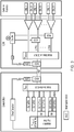
- Fig. 3 shows the proposed downlink architecture using mode selective MUX/DEMUXs.
- the crosstalk can be mitigated by compensating only for the crosstalk taking place between the degenerate modes.
- the crosstalk terms between degenerate modes show low dependency on the frequency.
- the crosstalk terms can be estimated by using pilot tones (in-band and/or out-of-band).
- the electrical channel estimation/inversion at the central office for the downlink is based on pilot tones (PT) that are retrieved after the mode selective DEMUX at the ODN before the optical splitters, as shown in Fig. 3 .
- PT pilot tones
- the signals at the mode DEMUX cannot be simply mirrored back since they would undergo through additional crosstalk along the uplink.
- the invention proposes the usage of quasi-single mode transmission for the retrieval of the pilot tones using one (or more) of the non-degenerate modes (LP01, LP02, ..., LP0x,.).
- the outputs from the mode DEMUX which correspond to pairs of degenerate modes are tapped (e.g.
- the usage of more than one of the LP0x modes allows to reduce the coupling losses (see point M in Fig. 3 ).
- the pilot tones of the pair LP11a/LP11b can be transmitted over LP01 and the pilot tones of the pair LP21a/LP21b can be transmitted over LP02.
- two 2 ⁇ 1 couplers can be used instead of one 4 ⁇ 1 coupler (the losses of the coupler scale with the number of ports).
- the channel estimation can be carried out relying on one pilot tone per pair of degenerate modes or two pilot tones with different frequencies per pair of degenerate modes. Moreover, in order to avoid the interference between pilot tones when they are coupled together after the mode DEMUX, unique frequencies can be addressed to each pair of degenerated modes.
- the transmitted PTs are directly detected at the central office, these are used for the blind estimation of the 2 ⁇ 2 matrices that describe the mode coupling LP11a and LP11b, and the mode coupling between LP21a and LP21b.
- the subsequent information symbols are pre-equalized with this estimated matrices in such a way the information can be successfully recovered at the ONUs.
- Fig. 4 shows the error free bandwidth as function of the FMF crosstalk.
- the results show that for a fibre presenting a crosstalk strength of -25 dB/km, the method proposed would be able to compensate the crosstalk between the degenerate modes over 5 nm. On the other hand, for a fibre with a crosstalk around -34 dB/km, the method proposed would be able to compensate the crosstalk between the degenerate modes over 32 nm (the whole extended C-band).
- Table 1 present a list of properties of several FMFs presented in the literature. It can be see that they present a crosstalk strength of between - 30 and -40 dB/km. The present invention can thus be expected to enable meaningful compensation using such FMFs.
- Table 1 Properties of known FMFs Fibre XT [dB/km] LP modes Refractive-Index Profile Reference [1] -39.77 3 Graded-Index L. Grüner-Nielsen, et al., J. Lightw. Technol., 30(23), p. 3693, 2012 . [2] -36.53 3 Step-Index A. Li, et al., Proc. OFC'2011, p. PDPB8 . [3] -33.19 3 Graded-Index R. Ryf, et al., J. Lightw. Technol., 30(4), p. 521, 2012 . [4] -30.21 6 Graded-Index T. Mori, et al., Proc. OFC'2013, p. OTh3K.1 .
- Fig. 5 shows a proposed downlink architecture using mode non-selective MUX/DEMUXs.
- the crosstalk can only be mitigated by compensating for the full set of modes.
- the DMD between non-degenerate modes is usually high (10-100 ps/km and higher), the channel matrix is frequency dependent. Thereby, pilot tones cannot be used. Instead it is proposed to use training sequences to perform channel estimation. Note that the architecture in Fig. 5 would be equally valid when using mode selective MUX/DEMUX. However, in that case, the usage of pilot tones is possible and the architecture in Fig. 5 could be simplified to match the architecture presented in Fig. 3 , as explained above.
- the electrical channel estimation/inversion at the central office for the downlink is based on training sequences that are retrieved after the mode non-selective DEMUX at the ODN before the optical splitters, as shown in Fig. 5 .
- the downlink signals are tapped just after the mode DEMUX (see Fig. 5 ) so that they can be returned to the central office and be used to estimate the crosstalk characteristic of the optical transfer unit.
- the uplink reference signal unlike the downlink reference signals, which can be sent in parallel, the uplink reference signal must send the training sequences in series if a quasi-single mode transmission is used.
- the tapped signals are added together to form the uplink reference signal after going through different delays. In order to be able to accommodate such delays, time guard bands are included around the training sequences.
- FIG. 6 shows an idealized representation of the training sequences at different points of the architecture shown in Fig. 5 .
- MIMO multiple-input multiple-output
- each training sequence sample must fulfil the following: T TS ⁇ N ⁇ ⁇ T ch + G
- v g slowest and v g fastest are the group velocities of the slowest and fastest modes, respectively.
- Equation 4 can be modified to consider any deviation when delaying the different mode-demultiplexed signals in point B of Fig. 5 .
- the retrieval of the training sequences can be done through more than one LP0x mode.
- the coupling losses at point M ( Fig. 5 ) can be reduced, as explained for the first prototype.
- using more than one LP0x mode has one more advantage, it also allows for the reduction of the time guard band.
- the TS of the LP01, LP11a and LP11b can be transmitted back over LP01 and the TS of LP02, LP21a and LP21b can be transmitted over LP02.
- the T GB can be reduced by a factor of two.
- similar reasoning applies.
- the performance of a MDM system supporting 3 modes (LP01, LP11a, LP11b) and one 40 Gbps QPSK system per mode is modelled and simulated.
- the pre-equalization at the CO is achieved using a coherent receiver to estimate the downlink transfer matrix from the training sequences being retrieved just after the mode DEMUX.
- a simple direct detection ONU (without DSP) is used.
- the crosstalk introduced by the fibre is varied from -50 dB/km to 0 dB/km, the mode non-selective MUX/DEMUX are considered to introduce an arbitrary high crosstalk value (full mixing), and the LP01 mode launch/select scheme is assumed to be ideal.
- the fibre is assumed to introduce a differential mode delay of 40 ps/km between LP01 and LP11a/b and 1 ps/km between LP11a and LP11b.
- Fig. 7 shows the Q-factor as a function of the fibre crosstalk, where the Q-factor of the worst mode is presented.
- the results show that for a fibre presenting a crosstalk strength as high as -20 dB/km, the prototype proposed would be able to correctly pre-compensate the crosstalk for the full set of modes.
- the implementation of the architecture presented in Fig. 3 may use an electrical feedback loop circuit to command the electrical butterfly coefficients of the FIR filters that are used to provide pre-compensation.
- the implementation of the architecture in Fig. 5 may use an array of optical delay lines for the parallel-to-serial conversion of the transmitted downlink training sequences.
- the mode selective MUX/DEMUX can be implemented using phase plates in a free-space optics configuration as shown in Fig. 8 .
- the embodiments discussed above can present several advantages. Both embodiments concentrate the signal processing effort in the central office, thereby avoiding the usage of digital signal processing in the ONUs.
- the embodiment that uses a mode selective MUX/DEMUX simplifies the OLT: it simplifies the transmitter as only pilot tones are required, and it simplifies the receiver as only the usage of direct detection and simple electrical butterfly fir filters are required.
- the embodiment that uses a mode non-selective MUX/DEMUX allows the usage of lower cost optical components however it requires the usage of field detection techniques and digital signal processing.
- pilot tone can be used per each pair of degenerate modes. Moreover, each pilot tone will have a different frequency such that when they are added after the DEMUX no interference takes place.
- the pilot tones can be used to update the FIR filter coefficients in two ways:
- the pilot tones may be low-frequency in-band tones or out-of-band high frequency tones.
- the pilot tones can be either phase-modulated either amplitude-modulated.
Landscapes
- Engineering & Computer Science (AREA)
- Computer Networks & Wireless Communication (AREA)
- Signal Processing (AREA)
- Physics & Mathematics (AREA)
- Electromagnetism (AREA)
- Computing Systems (AREA)
- Optical Communication System (AREA)
Claims (9)
- Réseau optique passif à multiplexage par division modale comprenant :une pluralité de canaux d'entrée, chacun de la pluralité des canaux d'entrée étant configuré pour véhiculer un signal optique d'entrée dans l'un différent d'une pluralité de modes ;une unité de transfert optique comprenant :un multiplexeur ayant une pluralité de ports d'entrée et un port de sortie, dans lequel chacun de la pluralité de ports d'entrée est connecté à l'un respectif de la pluralité de canaux d'entrée ;une fibre optique ayant une extrémité de liaison montante connectée au port de sortie, dans lequel la fibre optique est configurée pour recevoir du multiplexeur un signal muliplexé en mode correspondant aux signaux optiques d'entrée provenant de la pluralité de canaux d'entrée ; etun démultiplexeur ayant un port d'entrée et une pluralité de ports de sortie, dans lequel le port d'entrée est connecté à une extrémité de liaison descendante de la fibre optique, et dans lequel le démultiplexeur est configuré pour diviser le signal multiplexé en mode entre chacun de la pluralité de ports de sortie ; etune pluralité de canaux de sortie, chacun de la pluralité de canaux de sortie étant connecté à l'un respectif de la pluralité de ports de sortie et étant configuré pour transporter un signal optique de sortie dans l'un différent de la pluralité de modes véhiculés par la pluralité de canaux d'entrée,dans lequel l'unité de transfert optique est configurée pour :transmettre une pluralité de signaux de référence de liaison descendante dans le signal multiplexé en mode, chacun de la pluralité de signaux de référence de liaison descendante étant dans un mode différent de la pluralité de modes,recevoir la pluralité de signaux de référence de liaison descendante au niveau de la pluralité de ports de sortie,coupler la pluralité reçue de signaux de référence de liaison descendante en un signal de référence de liaison montante,transmettre le signal de référence de liaison montante dans une transmission quasi monomode le long de la fibre optique, etrecevoir le signal de référence de liaison montante au niveau de l'extrémité de liaison montante de la fibre optique ; etdans lequel le réseau optique passif comprend en outre un module de pré-compensation de signal de liaison descendante configuré pour adapter les signaux optiques sur deux ou plus de la pluralité de canaux d'entrée pour pré-compenser la diaphonie dans l'unité de transfert optique,dans lequel le module de pré-compensation de signal de liaison descendante peut être commandé sur la base du signal de référence de liaison montante reçu.
- Réseau selon la revendication 1, dans lequel le multiplexeur est à mode sélectif.
- Réseau selon la revendication 2, dans lequel les signaux de référence de liaison descendante sont des tonalités pilotes transmises sur des paires de modes dégénérés dans la pluralité de modes.
- Réseau selon la revendication 2 ou 3, dans lequel le module de pré-compensation de liaison descendante comprend un filtre FIR papillon électrique sur chacun des deux ou plus de la pluralité de canaux d'entrée.
- Réseau selon la revendication 1, dans lequel chaque signal de référence de liaison descendante comprend une séquence d'apprentissage transmise dans un intervalle de temps de séquence d'apprentissage de liaison descendante.
- Réseau selon la revendication 5, dans lequel l'intervalle de temps de séquence d'apprentissage comprend une bande de garde ayant une durée suffisamment longue pour englober une séquence d'apprentissage de liaison montante qui comprend les signaux de référence de liaison descendante reçus en série.
- Réseau selon l'une quelconque des revendications précédentes, dans lequel le signal de référence de liaison montante est transmis en utilisant un mode non dégénéré dans la pluralité de modes.
- Réseau selon l'une quelconque des revendications précédentes, dans lequel la fibre optique est une fibre à peu de modes, FMF, capable de supporter une propagation dans une pluralité de modes dégénérés et non générés.
- Procédé de compensation de diaphonie dans un réseau optique passif à multiplexage par division modale, le procédé comprenant les étapes consistant à :entrer une pluralité de signaux de référence de liaison descendante dans un multiplexeur qui est connecté à une extrémité de liaison montante d'une fibre optique, chacun de la pluralité de signaux de référence de liaison descendante étant dans l'un différent d'une pluralité de modes ;transmettre la pluralité de signaux de référence de liaison descendante en tant que signal multiplexé en mode le long de la fibre optique ;recevoir le signal multiplexé en mode au niveau d'un port d'entrée d'un démultiplexeur, dans lequel le port d'entrée est connecté à une extrémité de liaison descendante de la fibre optique ;délivrer en sortie une pluralité de signaux de référence de liaison descendante reçus du démultiplexeur, chacun de la pluralité reçue de signaux de référence de liaison descendante étant dans l'un différent d'une pluralité de modes ;coupler la pluralité reçue de signaux de référence de liaison descendante en un signal de référence de liaison montante,transmettre le signal de référence de liaison montante dans une transmission quasi monomode le long de la fibre optique,recevoir le signal de référence de liaison montante au niveau de l'extrémité de liaison montante de la fibre optique, etadapter une pluralité de signaux optiques entrés vers le multiplexeur sur la base du signal de référence de liaison montante pour pré-compenser la diaphonie.
Applications Claiming Priority (2)
| Application Number | Priority Date | Filing Date | Title |
|---|---|---|---|
| GBGB1516759.6A GB201516759D0 (en) | 2015-09-22 | 2015-09-22 | Mode division multiplexed passive optical network |
| PCT/EP2016/072526 WO2017050886A1 (fr) | 2015-09-22 | 2016-09-22 | Réseau optique passif à multiplexage par division modale |
Publications (2)
| Publication Number | Publication Date |
|---|---|
| EP3353920A1 EP3353920A1 (fr) | 2018-08-01 |
| EP3353920B1 true EP3353920B1 (fr) | 2020-06-17 |
Family
ID=54544618
Family Applications (1)
| Application Number | Title | Priority Date | Filing Date |
|---|---|---|---|
| EP16770016.0A Active EP3353920B1 (fr) | 2015-09-22 | 2016-09-22 | Réseau optique passif à multiplexage par division modale |
Country Status (5)
| Country | Link |
|---|---|
| US (1) | US10193619B2 (fr) |
| EP (1) | EP3353920B1 (fr) |
| CN (1) | CN108496316B (fr) |
| GB (1) | GB201516759D0 (fr) |
| WO (1) | WO2017050886A1 (fr) |
Cited By (1)
| Publication number | Priority date | Publication date | Assignee | Title |
|---|---|---|---|---|
| WO2026064065A1 (fr) * | 2024-09-19 | 2026-03-26 | Taara Connect, Inc. | Système de conjugaison de vecteurs de phase et d'amplitude de circuit intégré photonique à réseau optique à commande de phase bidimensionnel et système de conjugaison de vecteur d'amplitude pour des applications de fibre multimode |
Families Citing this family (8)
| Publication number | Priority date | Publication date | Assignee | Title |
|---|---|---|---|---|
| US20170208609A1 (en) * | 2016-01-20 | 2017-07-20 | Microchip Technology Incorporated | Time Triggered Communication Channel In A Synchronous Network |
| CN106992835B (zh) * | 2017-04-28 | 2019-04-02 | 中山大学 | 模分复用光纤通信系统的构建方法及构建的光纤通信系统 |
| ES3016309T3 (en) | 2018-08-07 | 2025-05-08 | Nippon Telegraph & Telephone | Optical transport system |
| CN112714369B (zh) * | 2019-10-25 | 2022-12-16 | 上海诺基亚贝尔股份有限公司 | 用于光通信的方法、设备、装置和计算机可读介质 |
| US11159238B1 (en) | 2020-08-11 | 2021-10-26 | Juniper Networks, Inc. | External laser enabled co-packaged optics architectures |
| EP4333328A4 (fr) | 2021-04-30 | 2025-03-05 | Nippon Telegraph And Telephone Corporation | Dispositif de noeud de connexion, système de transmission optique et procédé de connexion |
| US11811498B2 (en) * | 2021-05-13 | 2023-11-07 | Huawei Technologies Co., Ltd. | Methods and apparatus for feedback control of mode MUX and DEMUX |
| CN116634311A (zh) * | 2023-05-30 | 2023-08-22 | 南京信息工程大学 | 基于分布式深度神经网络模场识别的多模串扰分析方法 |
Family Cites Families (10)
| Publication number | Priority date | Publication date | Assignee | Title |
|---|---|---|---|---|
| AU2003231349A1 (en) * | 2002-05-28 | 2003-12-12 | Optun (Bvi) Ltd. | Method and apparatus for optical mode division multiplexing and demultiplexing |
| GB2428149B (en) | 2005-07-07 | 2009-10-28 | Agilent Technologies Inc | Multimode optical fibre communication system |
| DE102007015225A1 (de) | 2007-03-29 | 2008-10-09 | Siemens Ag | Verfahren zur Ermittlung einer Modengruppenmischungsmatrix eines Multimoden-Lichtwellenleiters und optische Übertragungssysteme |
| JP5281161B2 (ja) | 2009-07-08 | 2013-09-04 | 株式会社フジクラ | 光ファイバ通信システム |
| EP2521289B1 (fr) * | 2011-05-04 | 2014-03-05 | Alcatel Lucent | Récepteur optique pour communications multimode |
| US8965217B2 (en) | 2012-12-10 | 2015-02-24 | Corning Incorporated | Superimposing optical transmission modes |
| CN103152099B (zh) * | 2013-01-31 | 2016-05-25 | 华中科技大学 | 基于模分复用的单纤双向传输系统 |
| US9479285B2 (en) | 2013-10-14 | 2016-10-25 | Nec Corporation | Non-binary LDPC coded mode-multiplexed four-dimensional signaling based on orthogonal frequency division multiplexing |
| CN106664638A (zh) * | 2014-12-31 | 2017-05-10 | 华为技术有限公司 | 一种数据传输的方法、装置和系统 |
| GB2542109A (en) * | 2015-06-26 | 2017-03-15 | Univ Aston | Mode division multiplexed passive optical network |
-
2015
- 2015-09-22 GB GBGB1516759.6A patent/GB201516759D0/en not_active Ceased
-
2016
- 2016-09-22 CN CN201680066261.0A patent/CN108496316B/zh not_active Expired - Fee Related
- 2016-09-22 EP EP16770016.0A patent/EP3353920B1/fr active Active
- 2016-09-22 WO PCT/EP2016/072526 patent/WO2017050886A1/fr not_active Ceased
- 2016-09-22 US US15/762,386 patent/US10193619B2/en not_active Expired - Fee Related
Non-Patent Citations (1)
| Title |
|---|
| None * |
Cited By (1)
| Publication number | Priority date | Publication date | Assignee | Title |
|---|---|---|---|---|
| WO2026064065A1 (fr) * | 2024-09-19 | 2026-03-26 | Taara Connect, Inc. | Système de conjugaison de vecteurs de phase et d'amplitude de circuit intégré photonique à réseau optique à commande de phase bidimensionnel et système de conjugaison de vecteur d'amplitude pour des applications de fibre multimode |
Also Published As
| Publication number | Publication date |
|---|---|
| CN108496316B (zh) | 2020-01-07 |
| EP3353920A1 (fr) | 2018-08-01 |
| US10193619B2 (en) | 2019-01-29 |
| WO2017050886A1 (fr) | 2017-03-30 |
| US20180302154A1 (en) | 2018-10-18 |
| GB201516759D0 (en) | 2015-11-04 |
| CN108496316A (zh) | 2018-09-04 |
Similar Documents
| Publication | Publication Date | Title |
|---|---|---|
| EP3353920B1 (fr) | Réseau optique passif à multiplexage par division modale | |
| US6925262B2 (en) | Method and system for compensating chromatic dispersion | |
| CN108028718B (zh) | 模分复用无源光网络 | |
| Tang et al. | Coherent optical OFDM transmission up to 1 Tb/s per channel | |
| JP4870169B2 (ja) | 光ネットワークを経由する中心端末及び複数のクライアント端末の間の光通信 | |
| Benyahya et al. | High-speed bi-directional transmission over multimode fiber link in IM/DD systems | |
| US20020114034A1 (en) | Split wave method and apparatus for transmitting data in long-haul optical fiber systems | |
| US7542678B2 (en) | Method and apparatus for a supervisory channel in a WDM fiber-optic communication system | |
| Kawai et al. | Toward Petabit Per Second in Field: Ultrahigh-Capacity Terrestrial Transmission System With Coupled-Core Multi-Core Fibers | |
| JPH0918453A (ja) | 波長多重伝送方式の雑音抑圧方法 | |
| US7254342B2 (en) | Method and system for transmitting information in an optical communication system with low signal distortion | |
| Meseguer et al. | Experimental evaluation of multi-core fiber performance for SDM submarine systems at distances up to 20512 km | |
| CN101697499A (zh) | 色散补偿的装置及方法 | |
| EP1554822B1 (fr) | Attenuation touchant au domaine electrique d'effets dependant de la polarisation dans un systeme optique de communication | |
| Du et al. | Optical inverse Fourier transform generated 11.2-Tbit/s no-guard-interval all-optical OFDM transmission | |
| JP2006304170A (ja) | Ponシステムおよびponシステムの分散補償方法 | |
| Benyahya et al. | 14.5 Tb/s mode-group and wavelength multiplexed direct detection transmission over 2.2 km OM2 fiber | |
| JP4056846B2 (ja) | 分散モニタ装置、分散モニタ方法および自動分散補償システム | |
| Lobato et al. | The impact of differential mode delay on mode-division multiplexed coherent optical OFDM transmission | |
| US7672595B1 (en) | Optical transmission system architecture supporting migration to electronic compensation of link impairments | |
| Shan et al. | Simulation and analysis of optical WDM system using FBG as dispersion compensator | |
| Koebele et al. | Two-mode transmission with digital inter-modal cross-talk mitigation | |
| JP4916387B2 (ja) | センタ側光通信装置および光通信システム | |
| Xia et al. | 92-Gb/s field trial with ultra-high PMD tolerance of 107-ps DGD | |
| Abdo et al. | Adaptive Pre-Compensation of ROADMs in Coherent Optical Transponders |
Legal Events
| Date | Code | Title | Description |
|---|---|---|---|
| STAA | Information on the status of an ep patent application or granted ep patent |
Free format text: STATUS: THE INTERNATIONAL PUBLICATION HAS BEEN MADE |
|
| PUAI | Public reference made under article 153(3) epc to a published international application that has entered the european phase |
Free format text: ORIGINAL CODE: 0009012 |
|
| STAA | Information on the status of an ep patent application or granted ep patent |
Free format text: STATUS: REQUEST FOR EXAMINATION WAS MADE |
|
| 17P | Request for examination filed |
Effective date: 20180412 |
|
| AK | Designated contracting states |
Kind code of ref document: A1 Designated state(s): AL AT BE BG CH CY CZ DE DK EE ES FI FR GB GR HR HU IE IS IT LI LT LU LV MC MK MT NL NO PL PT RO RS SE SI SK SM TR |
|
| AX | Request for extension of the european patent |
Extension state: BA ME |
|
| DAV | Request for validation of the european patent (deleted) | ||
| DAX | Request for extension of the european patent (deleted) | ||
| GRAP | Despatch of communication of intention to grant a patent |
Free format text: ORIGINAL CODE: EPIDOSNIGR1 |
|
| STAA | Information on the status of an ep patent application or granted ep patent |
Free format text: STATUS: GRANT OF PATENT IS INTENDED |
|
| RIC1 | Information provided on ipc code assigned before grant |
Ipc: H04B 10/2569 20130101ALI20191213BHEP Ipc: H04B 10/50 20130101ALI20191213BHEP Ipc: H04J 14/04 20060101AFI20191213BHEP Ipc: H04B 10/272 20130101ALI20191213BHEP |
|
| INTG | Intention to grant announced |
Effective date: 20200113 |
|
| GRAS | Grant fee paid |
Free format text: ORIGINAL CODE: EPIDOSNIGR3 |
|
| GRAA | (expected) grant |
Free format text: ORIGINAL CODE: 0009210 |
|
| STAA | Information on the status of an ep patent application or granted ep patent |
Free format text: STATUS: THE PATENT HAS BEEN GRANTED |
|
| AK | Designated contracting states |
Kind code of ref document: B1 Designated state(s): AL AT BE BG CH CY CZ DE DK EE ES FI FR GB GR HR HU IE IS IT LI LT LU LV MC MK MT NL NO PL PT RO RS SE SI SK SM TR |
|
| REG | Reference to a national code |
Ref country code: GB Ref legal event code: FG4D |
|
| REG | Reference to a national code |
Ref country code: CH Ref legal event code: EP |
|
| REG | Reference to a national code |
Ref country code: IE Ref legal event code: FG4D |
|
| REG | Reference to a national code |
Ref country code: DE Ref legal event code: R096 Ref document number: 602016038315 Country of ref document: DE |
|
| REG | Reference to a national code |
Ref country code: AT Ref legal event code: REF Ref document number: 1282633 Country of ref document: AT Kind code of ref document: T Effective date: 20200715 |
|
| PG25 | Lapsed in a contracting state [announced via postgrant information from national office to epo] |
Ref country code: SE Free format text: LAPSE BECAUSE OF FAILURE TO SUBMIT A TRANSLATION OF THE DESCRIPTION OR TO PAY THE FEE WITHIN THE PRESCRIBED TIME-LIMIT Effective date: 20200617 Ref country code: LT Free format text: LAPSE BECAUSE OF FAILURE TO SUBMIT A TRANSLATION OF THE DESCRIPTION OR TO PAY THE FEE WITHIN THE PRESCRIBED TIME-LIMIT Effective date: 20200617 Ref country code: FI Free format text: LAPSE BECAUSE OF FAILURE TO SUBMIT A TRANSLATION OF THE DESCRIPTION OR TO PAY THE FEE WITHIN THE PRESCRIBED TIME-LIMIT Effective date: 20200617 Ref country code: NO Free format text: LAPSE BECAUSE OF FAILURE TO SUBMIT A TRANSLATION OF THE DESCRIPTION OR TO PAY THE FEE WITHIN THE PRESCRIBED TIME-LIMIT Effective date: 20200917 Ref country code: GR Free format text: LAPSE BECAUSE OF FAILURE TO SUBMIT A TRANSLATION OF THE DESCRIPTION OR TO PAY THE FEE WITHIN THE PRESCRIBED TIME-LIMIT Effective date: 20200918 |
|
| REG | Reference to a national code |
Ref country code: LT Ref legal event code: MG4D |
|
| REG | Reference to a national code |
Ref country code: NL Ref legal event code: MP Effective date: 20200617 |
|
| PG25 | Lapsed in a contracting state [announced via postgrant information from national office to epo] |
Ref country code: LV Free format text: LAPSE BECAUSE OF FAILURE TO SUBMIT A TRANSLATION OF THE DESCRIPTION OR TO PAY THE FEE WITHIN THE PRESCRIBED TIME-LIMIT Effective date: 20200617 Ref country code: HR Free format text: LAPSE BECAUSE OF FAILURE TO SUBMIT A TRANSLATION OF THE DESCRIPTION OR TO PAY THE FEE WITHIN THE PRESCRIBED TIME-LIMIT Effective date: 20200617 Ref country code: BG Free format text: LAPSE BECAUSE OF FAILURE TO SUBMIT A TRANSLATION OF THE DESCRIPTION OR TO PAY THE FEE WITHIN THE PRESCRIBED TIME-LIMIT Effective date: 20200917 Ref country code: RS Free format text: LAPSE BECAUSE OF FAILURE TO SUBMIT A TRANSLATION OF THE DESCRIPTION OR TO PAY THE FEE WITHIN THE PRESCRIBED TIME-LIMIT Effective date: 20200617 |
|
| REG | Reference to a national code |
Ref country code: AT Ref legal event code: MK05 Ref document number: 1282633 Country of ref document: AT Kind code of ref document: T Effective date: 20200617 |
|
| PG25 | Lapsed in a contracting state [announced via postgrant information from national office to epo] |
Ref country code: NL Free format text: LAPSE BECAUSE OF FAILURE TO SUBMIT A TRANSLATION OF THE DESCRIPTION OR TO PAY THE FEE WITHIN THE PRESCRIBED TIME-LIMIT Effective date: 20200617 Ref country code: AL Free format text: LAPSE BECAUSE OF FAILURE TO SUBMIT A TRANSLATION OF THE DESCRIPTION OR TO PAY THE FEE WITHIN THE PRESCRIBED TIME-LIMIT Effective date: 20200617 |
|
| PG25 | Lapsed in a contracting state [announced via postgrant information from national office to epo] |
Ref country code: IT Free format text: LAPSE BECAUSE OF FAILURE TO SUBMIT A TRANSLATION OF THE DESCRIPTION OR TO PAY THE FEE WITHIN THE PRESCRIBED TIME-LIMIT Effective date: 20200617 Ref country code: RO Free format text: LAPSE BECAUSE OF FAILURE TO SUBMIT A TRANSLATION OF THE DESCRIPTION OR TO PAY THE FEE WITHIN THE PRESCRIBED TIME-LIMIT Effective date: 20200617 Ref country code: CZ Free format text: LAPSE BECAUSE OF FAILURE TO SUBMIT A TRANSLATION OF THE DESCRIPTION OR TO PAY THE FEE WITHIN THE PRESCRIBED TIME-LIMIT Effective date: 20200617 Ref country code: PT Free format text: LAPSE BECAUSE OF FAILURE TO SUBMIT A TRANSLATION OF THE DESCRIPTION OR TO PAY THE FEE WITHIN THE PRESCRIBED TIME-LIMIT Effective date: 20201019 Ref country code: ES Free format text: LAPSE BECAUSE OF FAILURE TO SUBMIT A TRANSLATION OF THE DESCRIPTION OR TO PAY THE FEE WITHIN THE PRESCRIBED TIME-LIMIT Effective date: 20200617 Ref country code: EE Free format text: LAPSE BECAUSE OF FAILURE TO SUBMIT A TRANSLATION OF THE DESCRIPTION OR TO PAY THE FEE WITHIN THE PRESCRIBED TIME-LIMIT Effective date: 20200617 Ref country code: AT Free format text: LAPSE BECAUSE OF FAILURE TO SUBMIT A TRANSLATION OF THE DESCRIPTION OR TO PAY THE FEE WITHIN THE PRESCRIBED TIME-LIMIT Effective date: 20200617 Ref country code: SM Free format text: LAPSE BECAUSE OF FAILURE TO SUBMIT A TRANSLATION OF THE DESCRIPTION OR TO PAY THE FEE WITHIN THE PRESCRIBED TIME-LIMIT Effective date: 20200617 |
|
| PG25 | Lapsed in a contracting state [announced via postgrant information from national office to epo] |
Ref country code: PL Free format text: LAPSE BECAUSE OF FAILURE TO SUBMIT A TRANSLATION OF THE DESCRIPTION OR TO PAY THE FEE WITHIN THE PRESCRIBED TIME-LIMIT Effective date: 20200617 Ref country code: SK Free format text: LAPSE BECAUSE OF FAILURE TO SUBMIT A TRANSLATION OF THE DESCRIPTION OR TO PAY THE FEE WITHIN THE PRESCRIBED TIME-LIMIT Effective date: 20200617 Ref country code: IS Free format text: LAPSE BECAUSE OF FAILURE TO SUBMIT A TRANSLATION OF THE DESCRIPTION OR TO PAY THE FEE WITHIN THE PRESCRIBED TIME-LIMIT Effective date: 20201017 |
|
| REG | Reference to a national code |
Ref country code: DE Ref legal event code: R097 Ref document number: 602016038315 Country of ref document: DE |
|
| REG | Reference to a national code |
Ref country code: DE Ref legal event code: R119 Ref document number: 602016038315 Country of ref document: DE |
|
| PLBE | No opposition filed within time limit |
Free format text: ORIGINAL CODE: 0009261 |
|
| STAA | Information on the status of an ep patent application or granted ep patent |
Free format text: STATUS: NO OPPOSITION FILED WITHIN TIME LIMIT |
|
| PG25 | Lapsed in a contracting state [announced via postgrant information from national office to epo] |
Ref country code: DK Free format text: LAPSE BECAUSE OF FAILURE TO SUBMIT A TRANSLATION OF THE DESCRIPTION OR TO PAY THE FEE WITHIN THE PRESCRIBED TIME-LIMIT Effective date: 20200617 |
|
| REG | Reference to a national code |
Ref country code: CH Ref legal event code: PL |
|
| 26N | No opposition filed |
Effective date: 20210318 |
|
| GBPC | Gb: european patent ceased through non-payment of renewal fee |
Effective date: 20200922 |
|
| PG25 | Lapsed in a contracting state [announced via postgrant information from national office to epo] |
Ref country code: SI Free format text: LAPSE BECAUSE OF FAILURE TO SUBMIT A TRANSLATION OF THE DESCRIPTION OR TO PAY THE FEE WITHIN THE PRESCRIBED TIME-LIMIT Effective date: 20200617 |
|
| REG | Reference to a national code |
Ref country code: BE Ref legal event code: MM Effective date: 20200930 |
|
| PG25 | Lapsed in a contracting state [announced via postgrant information from national office to epo] |
Ref country code: LU Free format text: LAPSE BECAUSE OF NON-PAYMENT OF DUE FEES Effective date: 20200922 |
|
| PG25 | Lapsed in a contracting state [announced via postgrant information from national office to epo] |
Ref country code: DE Free format text: LAPSE BECAUSE OF NON-PAYMENT OF DUE FEES Effective date: 20210401 Ref country code: FR Free format text: LAPSE BECAUSE OF NON-PAYMENT OF DUE FEES Effective date: 20200930 |
|
| PG25 | Lapsed in a contracting state [announced via postgrant information from national office to epo] |
Ref country code: LI Free format text: LAPSE BECAUSE OF NON-PAYMENT OF DUE FEES Effective date: 20200930 Ref country code: IE Free format text: LAPSE BECAUSE OF NON-PAYMENT OF DUE FEES Effective date: 20200922 Ref country code: GB Free format text: LAPSE BECAUSE OF NON-PAYMENT OF DUE FEES Effective date: 20200922 Ref country code: BE Free format text: LAPSE BECAUSE OF NON-PAYMENT OF DUE FEES Effective date: 20200930 Ref country code: CH Free format text: LAPSE BECAUSE OF NON-PAYMENT OF DUE FEES Effective date: 20200930 |
|
| PG25 | Lapsed in a contracting state [announced via postgrant information from national office to epo] |
Ref country code: TR Free format text: LAPSE BECAUSE OF FAILURE TO SUBMIT A TRANSLATION OF THE DESCRIPTION OR TO PAY THE FEE WITHIN THE PRESCRIBED TIME-LIMIT Effective date: 20200617 Ref country code: MT Free format text: LAPSE BECAUSE OF FAILURE TO SUBMIT A TRANSLATION OF THE DESCRIPTION OR TO PAY THE FEE WITHIN THE PRESCRIBED TIME-LIMIT Effective date: 20200617 Ref country code: CY Free format text: LAPSE BECAUSE OF FAILURE TO SUBMIT A TRANSLATION OF THE DESCRIPTION OR TO PAY THE FEE WITHIN THE PRESCRIBED TIME-LIMIT Effective date: 20200617 |
|
| PG25 | Lapsed in a contracting state [announced via postgrant information from national office to epo] |
Ref country code: MK Free format text: LAPSE BECAUSE OF FAILURE TO SUBMIT A TRANSLATION OF THE DESCRIPTION OR TO PAY THE FEE WITHIN THE PRESCRIBED TIME-LIMIT Effective date: 20200617 Ref country code: MC Free format text: LAPSE BECAUSE OF FAILURE TO SUBMIT A TRANSLATION OF THE DESCRIPTION OR TO PAY THE FEE WITHIN THE PRESCRIBED TIME-LIMIT Effective date: 20200617 |