EP3354123A1 - Appareil de traitement du sol agricole - Google Patents
Appareil de traitement du sol agricole Download PDFInfo
- Publication number
- EP3354123A1 EP3354123A1 EP18154167.3A EP18154167A EP3354123A1 EP 3354123 A1 EP3354123 A1 EP 3354123A1 EP 18154167 A EP18154167 A EP 18154167A EP 3354123 A1 EP3354123 A1 EP 3354123A1
- Authority
- EP
- European Patent Office
- Prior art keywords
- wing
- wing sections
- pressure medium
- locking
- cylinders
- Prior art date
- Legal status (The legal status is an assumption and is not a legal conclusion. Google has not performed a legal analysis and makes no representation as to the accuracy of the status listed.)
- Granted
Links
Images

Classifications
-
- A—HUMAN NECESSITIES
- A01—AGRICULTURE; FORESTRY; ANIMAL HUSBANDRY; HUNTING; TRAPPING; FISHING
- A01B—SOIL WORKING IN AGRICULTURE OR FORESTRY; PARTS, DETAILS, OR ACCESSORIES OF AGRICULTURAL MACHINES OR IMPLEMENTS, IN GENERAL
- A01B73/00—Means or arrangements to facilitate transportation of agricultural machines or implements, e.g. folding frames to reduce overall width
- A01B73/02—Folding frames
- A01B73/04—Folding frames foldable about a horizontal axis
- A01B73/044—Folding frames foldable about a horizontal axis the axis being oriented in a longitudinal direction
- A01B73/046—Folding frames foldable about a horizontal axis the axis being oriented in a longitudinal direction each folding frame part being foldable in itself
-
- A—HUMAN NECESSITIES
- A01—AGRICULTURE; FORESTRY; ANIMAL HUSBANDRY; HUNTING; TRAPPING; FISHING
- A01B—SOIL WORKING IN AGRICULTURE OR FORESTRY; PARTS, DETAILS, OR ACCESSORIES OF AGRICULTURAL MACHINES OR IMPLEMENTS, IN GENERAL
- A01B73/00—Means or arrangements to facilitate transportation of agricultural machines or implements, e.g. folding frames to reduce overall width
- A01B73/02—Folding frames
- A01B73/04—Folding frames foldable about a horizontal axis
- A01B73/044—Folding frames foldable about a horizontal axis the axis being oriented in a longitudinal direction
Definitions
- the present invention relates to an agricultural tillage implement for attachment to a tractor, with a machine frame on the side wings that carry tillage tools are hinged, the wings are each pivoting to the machine frame to a working position, at least approximately pointing in the direction of travel frame pivot axis and are each divided into at least two wing sections, which are mutually pivotable about a lying in working position, at least approximately pointing in the direction of travel wing pivot axis, wherein the wing sections are each connected by at least one Druckschaktor, undergoing changes in length of each wing movements during pivoting movements of the wing sections and pivoting movements of the wing sections their neutral position allows out both in one and the other opposite pivoting direction.
- Such a harrow can, for example, be a disc harrow, a cultivator, a cultivator or a seed drill or a device combination of various tillage tools, for example disc-shaped furrowing and / or cutting tools, cultivator tines, coulters, Have packer wheels or grooved roller element or other floor tools.
- the said tillage tools in one or more rows one behind the other, which extend in the working position transverse to the direction of travel, be arranged on said wings, so that each wing carries a variety of tillage tools possibly in one or more rows, said wings, for example cantilevered right and left of a central machine frame, when the wings are in their working position.
- said wings may extend several meters cantilevered or together form a working width of several meters, so that a completely rigid design of said wing no longer makes sense, since then the ground adjustment is insufficient and it is, for example Longitudinal furrows or lateral slope edges may cause the tillage tools in one wing section cut too deep into the ground, while in another wing section to little or no longer engage in the ground.
- the said wing pivot axes the wing sections both a Allow overstretching as well as an opposite bending, ie tilt an outer wing section in example, horizontally oriented inner wing section both down and up.
- the side wings may be pivoted about the aforementioned frame pivot axis upwards.
- the wings are hinged to a frame part, which can be pivoted about a lying, transverse to the direction of pivot axis, until the aforementioned frame pivot axes of the wings approximately upright and accordingly the wings then forward or can be pivoted at the rear until the wings extend approximately in the direction of travel parallel.
- the present invention has for its object to provide an improved agricultural tillage implement of the type mentioned above, which avoids the disadvantages of the prior art and the latter develops in an advantageous manner.
- an excellent ground adaptation should be achieved without having to accept instabilities when moving into the transport position or even in the transport position itself.
- said object is achieved by an agricultural soil cultivation device according to claim 1.
- Preferred embodiments of the invention are the subject of the dependent claims.
- the neutral position in particular can form a non-overextended and non-flexed middle position in which the wing sections extend at least approximately parallel to each other and / or approximately in a common plane.
- a locking device for locking the pressure medium actuator which connects two adjacent wing sections over the intermediate wing pivot axis away, provided in a locking position in which the wing sections are held in said neutral position. Due to the locking of the pressure medium actuator, an already existing component is also used for the additional function of locking and the corresponding locking forces transmitted via the pressure medium actuator, so that a space-saving, yet stable training and locking can be achieved.
- the said locking device may in this case be designed in particular hydraulically in order to hydraulically lock the pressure medium actuator, so that additional, special mechanical locking elements can be dispensed with.
- said locking position of the pressure medium actuator likewise forms an intermediate position of the pressure medium actuator in which the pressure medium actuator is between its maximum elongated and its maximum shortened position, ie assumes an intermediate length from which the pressure medium actuator both lengthened and can be shortened to unlocked For example, to allow work operation both overstretching and opposite bowing of the wing sections.
- the pressure medium actuator in development of the invention may have a stop position in which a pressure medium piston of the pressure medium actuator is driven against a stop and / or held by pressure medium on the stop.
- said stop position thereby forms said locking position and at the same time the aforementioned intermediate position in which the pressure medium actuator occupies an intermediate length between maximally elongated and maximum shortened position.
- the said pressure medium actuator may be formed as a double piston cylinder unit with two pistons and two cylinders, wherein in a further development of the invention, the two pistons axially fixedly connected to each other and the two cylinders can be arranged axially movable relative to each other.
- the two cylinders can also be connected to one another in an axially fixed manner and the two pistons can be arranged to be axially movable relative to one another.
- an advantageous embodiment of the invention may consist in that the double piston-cylinder unit comprises a common piston rod, on which the two pistons are mounted spaced apart, wherein a first of the two pistons in a first cylinder and a second of the two pistons in a second of the two cylinders each slidably received.
- the two cylinders can be connected to each other via said piston rod and moved axially relative to the piston on the said piston rod by the displaceability, wherein one of the cylinders can be articulated on a first wing section and the other cylinder on a second wing section.
- the double piston-cylinder unit may also comprise two separate piston rods which are each connected to a piston and each coupled to one of two adjacent wing sections.
- the piston of a piston rod in a first cylinder and the piston of the other piston rod be slidably received in a second cylinder, wherein the two said cylinders can be rigidly connected to each other, in particular back to back coaxially rigidly connected, so that the two Stand out piston rods on opposite sides of the cylinders and run the pistons in separate cylinder chambers.
- the two cylinders are each formed double-acting.
- Each piston can subdivide its cylinder into two cylinder chambers, wherein advantageously each of the two cylinder chambers can be pressurized on opposite sides of a piston.
- the pistons In a working position, the pistons can be moved displaceably in the cylinders so that the travel ranges of the pistons in the respective cylinder can add up.
- both pistons are advantageously driven toward the same side towards the end of the cylinder or the travel provided therein, so that the double-piston-cylinder unit assumes the aforementioned intermediate position, in which the double piston-cylinder unit occupies an overall average length.
- the pistons By pressurizing the respective pressure chambers in the two cylinders, the pistons can be hydraulically locked by being driven to the respective stops or front ends of the cylinder chambers.
- the hydraulic locking device can make do with a simple multiple-switching valve or multi-way switching valve, by which the pressure line of the hydraulic system are selectively switched to the required pressure chambers in the two cylinders and / or the non-pressurized chambers in the two cylinders with the tank or . Reservoir or return can be connected.
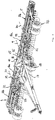
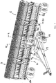
- the harrow 1 comprises a machine frame 2, which are mounted on a hitch 3 on a tractor, not shown, and may be supported by a chassis 4 on the ground.
- the harrow 1 may in particular be designed as a semi-mounted device which is attached by means of a drawbar on the tractor and is supported by the chassis 4 on the ground.
- two wings 5 and 6 are grown, projecting in the direction of travel 7 project laterally right and left of the machine frame 2, wherein said wings 5 and 6 may each include sash 8, which is to the machine frame 2 to frame pivot axes 9 and 10, which in the working position shown in accordance lying in Figures 1 and 2 lying in the direction of travel 7, can be pivoted.
- the cantilevered wings 5, 6 may be supported by a Tastfahrtechnik 33 on the ground, which may be arranged for example on outer, lateral portions of the wings 5, 6, see. Fig. 1 and 2.
- the wings 5 and 6 may be provided with tillage tools, which may be arranged in several rows transverse to the direction of travel behind each other, depending on the specific design of the tillage implement various floor tools 11 may be provided.
- the floor tools 11 may include one or more rows of coulter discs 12, which Scharstriegel 13 may be arranged downstream.
- a groove roller 14 may be provided on the wings 5 and 6.
- the wings 5 and 6 can hereby be pivoted about the said frame pivot axes 9 and 10 relative to the machine frame 2 by means of adjusting actuators 15, wherein the actuating actuators 15 can be provided to lift the wings 5 and 6, for example for the headland and / or the transport, and / or to press the wings 5 and 6 in the working position down to the ground to increase the Bodenantikkraft the bottom tools 11.
- the actuating actuators 15 may comprise, for example, hydraulic cylinders, which may be hinged on the one hand to the sash 8 and on the other hand to the machine frame 2.
- the wings 5 and 6 can be articulated via said frame pivot axes 9 and 10 on a swivel frame piece 16, which in turn is pivotally hinged to a central frame member 17, namely an advantageously lying, transversely to the direction of travel. 7 extending pivot axis 18 about which said pivot frame piece 16 can be tilted together with the hinged wings 5 and 6, until the frame pivot axes 9 and 10, which extend lying in the working position in the direction of travel, approximately vertically or extend upright, as shown in FIG. 3.
- the wings 5 and 6 can be pivoted about the frame pivot axes 9 and 10 forward in an approximately direction of travel parallel orientation, where they can be supported in the forward pivoted transport position on the machine frame 2.
- a Stellaktor 19 may be provided, for example in the form of a hydraulic cylinder, which may be articulated on the one hand on the swing frame piece 16 and on the other hand on the central frame piece 17, see.
- the two wings 5 and 6 can already perform a certain Bodenanpassterrorism and oblique slope contours and / or longitudinal waves or diagonal waves on and hinge off.
- the wings 5 and 6 are each divided into at least two wing segments 5a and 5b and 6a and 6b, wherein the respective adjacent wing segments 5a, 5b and 6a, 6b of a wing 5 and 6 by a Wing pivot axis 20 and 21 are pivotally connected to each other, said wing pivot axes 20, 21 between the wing segments 5a, 5b and 6a, 6b lying in working position lying in the direction of travel can extend.
- the adjacent wing sections 5a and 5b and 6a and 6b each other up and hinge down to better adapt to the bottom contour.
- the pivotal connection may be formed such that the outer pivoting section 5b or 6b is capable of pivoting both up and down relative to the inner pivoting section 5a and 6a, respectively, so that the wing sections 5a, 5b and 6a, 6b can assume both an overstretched and an oppositely bowed configuration.
- the wing sections 5a, 5b and 6a, 6b may be formed from the neutral position shown in FIGS. 1 and 2, in which the wing sections extend approximately parallel to each other and / or in a common plane and / or form an approximately generally planar wing, pivot both in one direction and in the opposite direction.
- said wing pivot axes 20 and 21 are associated with pressure-medium actuators 22, which in particular can be designed as hydraulic cylinders and two adjacent wing sections with bridging connect the wing pivot axes.
- the mentioned pressure-medium actuators 22 may in particular be provided for biasing the wing sections 5a, 5b and 6a, 6b rotationally relative to one another in the working position, wherein different prestressing directions may be adjustable or may be expedient depending on the design of the soil cultivating device.
- the pressure medium actuators 22 may bias the outer wing sections 5b and 6b downwardly toward the ground, respectively, to bias the ground pressure forces on the lateral edges of the wings increase.
- the aforementioned pressure-medium actuators 22 are designed to be double-acting and can be activated by a pressure-medium control device so that they can optionally provide a bias in one direction or in the opposite other direction.
- said pressure medium actuators 22 can be fixed or locked in a locking position, so that the wing sections 5a, 5b and 6a, 6b are fixed relative to each other in a certain position.
- the locking device 23 provided for this purpose is such that the pressure medium actuators 22 can be locked in a position in which the wing sections 5a, 5b and 6a, 6b are held in their neutral position, said neutral position forming an intermediate position as explained above can, which can be located between the maximum overstretched and the maximum oppositely bent position and in particular can form the position in which the wing sections extend approximately parallel and / or approximately in a common plane.
- the locking device 23 may be designed to lock the pivotable wing sections 5a, 5b and 6a, 6b in the desired working position for flat floors shown in FIGS. 1 and 2.
- the said locking device 23 is designed to work hydraulically to lock the pressure medium actuators 22 in the aforementioned locking position.
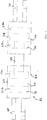
- the pressure medium actuators 22 may be formed as a double piston cylinder units 24, each comprising two pistons 25, 26 and two cylinders 27, 28.
- the double piston cylinder unit 24 shows the Fig. 4, according to which the two pistons 25 and 26 sit on a common piston rod 29 and thus can be connected axially fixed.
- the two pistons 25 and 26 are each slidably received in one of the two cylinders 27 and 28, said cylinders 27 and 28 are separated from each other and each have a hinge member 30 for articulating the double piston cylinder unit 24 at the wing sections to be pivoted.
- the pistons 25 and 26 subdivide their respective cylinders 27 and 28 into two pressure chambers 27a, 27b and 28a, 28b, respectively, so that each cylinder is double-acting or each piston in the respective cylinder 27 and 28 is optional in one or the opposite direction can be moved.
- the pressure chambers are pressurized so that the piston rod 29 moves into one cylinder and extends out of the other cylinder, for example, by pressurizing the piston rod-penetrated smaller pressure chamber 27a in the cylinder 27 and pressurizing the larger pressure chamber 28b in the other cylinder 28, the two pistons 25 move and 26 in their cylinders 27 and 28 respectively against a stop 30, 31, which may be formed by the end faces of the cylinder.
- the double piston cylinder unit 24 assumes an average length and holds the respective wing sections in their neutral position.
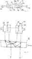
- the double-piston cylinder unit 24 may also comprise two separate piston rods 29 which each axially support a piston 25 and 26 and at their free, protruding ends, the coupling elements 30 may have to articulate the double piston cylinder unit 24 at the respective wing sections ,
- the pistons 25 and 26 are in turn received axially displaceable in cylinders 27 and 28, said cylinders 27 and 28, however, are axially fixed to each other, in particular back to back arranged coaxially and rigidly connected to each other, see. Fig. 5.
- the loading of the double piston cylinder unit 24 can be carried out in a simple manner by a multi-way switching valve 32, which may be formed, for example, as a 6/2 valve, if it is sufficient to adjust only one biasing direction next to the locking position, for example, to fully extended or elongated Standing down.
- a multi-way switching valve 32 which may be formed, for example, as a 6/2 valve, if it is sufficient to adjust only one biasing direction next to the locking position, for example, to fully extended or elongated Standing down.
- a 6/3 valve may be provided to selectively bias in one or the opposite direction and to lock additionally.
- switching valve need not be directly connected to the pressure source P and directly to the tank or return T, but it may also pressure reduction means may be provided, for example, to adjust the bias more or less and / or to adjust the locking force can.
Landscapes
- Life Sciences & Earth Sciences (AREA)
- Engineering & Computer Science (AREA)
- Mechanical Engineering (AREA)
- Soil Sciences (AREA)
- Environmental Sciences (AREA)
- Soil Working Implements (AREA)
Applications Claiming Priority (1)
| Application Number | Priority Date | Filing Date | Title |
|---|---|---|---|
| DE202017000493.3U DE202017000493U1 (de) | 2017-01-30 | 2017-01-30 | Landwirtschaftliches Bodenbearbeitungsgerät |
Publications (2)
| Publication Number | Publication Date |
|---|---|
| EP3354123A1 true EP3354123A1 (fr) | 2018-08-01 |
| EP3354123B1 EP3354123B1 (fr) | 2019-07-10 |
Family
ID=61094327
Family Applications (1)
| Application Number | Title | Priority Date | Filing Date |
|---|---|---|---|
| EP18154167.3A Active EP3354123B1 (fr) | 2017-01-30 | 2018-01-30 | Appareil de traitement du sol agricole |
Country Status (2)
| Country | Link |
|---|---|
| EP (1) | EP3354123B1 (fr) |
| DE (1) | DE202017000493U1 (fr) |
Families Citing this family (1)
| Publication number | Priority date | Publication date | Assignee | Title |
|---|---|---|---|---|
| DE102023117566A1 (de) | 2023-07-04 | 2025-01-09 | Pöttinger Landtechnik Gmbh | Landwirtschaftliche Bodenbearbeitungsmaschine |
Citations (4)
| Publication number | Priority date | Publication date | Assignee | Title |
|---|---|---|---|---|
| EP1179289A2 (fr) * | 2000-08-09 | 2002-02-13 | Deere & Company | Outil pliable de travail agricole |
| DE102007052353A1 (de) * | 2007-11-02 | 2009-05-07 | Alois Pöttinger Maschinenfabrik Gmbh | Sä- und/oder Bodenbearbeitungsmaschine |
| US20150068779A1 (en) * | 2013-09-06 | 2015-03-12 | Cnh Canada, Ltd. | Agricultural Implement with Compound Hinge Arrangement |
| EP3000298A1 (fr) * | 2014-09-05 | 2016-03-30 | SIP Strojna Industrija d.d. | Tedder rotatif |
Family Cites Families (2)
| Publication number | Priority date | Publication date | Assignee | Title |
|---|---|---|---|---|
| US4042044A (en) * | 1976-04-12 | 1977-08-16 | Deere & Company | Rear folding implement |
| DE9312326U1 (de) * | 1993-08-18 | 1993-12-09 | Karl Becker GmbH & Co KG Maschinenfabrik, 34399 Oberweser | Koppelvorrichtung für zwei landwirtschaftliche Maschinen |
-
2017
- 2017-01-30 DE DE202017000493.3U patent/DE202017000493U1/de active Active
-
2018
- 2018-01-30 EP EP18154167.3A patent/EP3354123B1/fr active Active
Patent Citations (4)
| Publication number | Priority date | Publication date | Assignee | Title |
|---|---|---|---|---|
| EP1179289A2 (fr) * | 2000-08-09 | 2002-02-13 | Deere & Company | Outil pliable de travail agricole |
| DE102007052353A1 (de) * | 2007-11-02 | 2009-05-07 | Alois Pöttinger Maschinenfabrik Gmbh | Sä- und/oder Bodenbearbeitungsmaschine |
| US20150068779A1 (en) * | 2013-09-06 | 2015-03-12 | Cnh Canada, Ltd. | Agricultural Implement with Compound Hinge Arrangement |
| EP3000298A1 (fr) * | 2014-09-05 | 2016-03-30 | SIP Strojna Industrija d.d. | Tedder rotatif |
Also Published As
| Publication number | Publication date |
|---|---|
| DE202017000493U1 (de) | 2018-05-03 |
| EP3354123B1 (fr) | 2019-07-10 |
Similar Documents
| Publication | Publication Date | Title |
|---|---|---|
| DE2838829A1 (de) | Mehrschariger aufsattelpflug | |
| AT508217B1 (de) | Bodenbearbeitungsvorrichtung | |
| EP4492955B1 (fr) | Outil agricole | |
| DE102017116633A1 (de) | Landwirtschaftliche Bodenbearbeitungsmaschine | |
| EP1529431B1 (fr) | Semoir | |
| EP2659758B1 (fr) | Charrue réversible | |
| EP2025215B1 (fr) | Machine de répartition de semences et/ou d'engrais | |
| EP3800976B1 (fr) | Appareil agricole de travail du sol et procédé permettant de faire fonctionner ledit appareil | |
| EP3242543B1 (fr) | Engin agricole à châssis de roulement supplémentaire | |
| DE102014015881B4 (de) | Bodenbearbeitungsmaschine | |
| EP3434089B1 (fr) | Machine agricole de traitement du sol | |
| EP3354123B1 (fr) | Appareil de traitement du sol agricole | |
| DE1455578C3 (de) | Steuervorrichtung für Ackerschlepper mit einem Dreipunktgestänge sowie einem hydraulischen Kraftheber | |
| AT403424B (de) | Mehrschariger pflug | |
| DE69419341T2 (de) | Bodenbearbeitungsmaschine | |
| EP2944170B1 (fr) | Épandeur agricole, en particulier semoir, et procédé de réglage en hauteur des socs | |
| DE3431796C2 (fr) | ||
| EP3598882B1 (fr) | Accessoire agricole | |
| EP4252503B1 (fr) | Faucheuse agricole pouvant fonctionner en poussée | |
| EP1529427B1 (fr) | Machine agricole à travail du sol et/ou de semis | |
| EP4122304B1 (fr) | Machine de travail agricole | |
| DE20219242U1 (de) | Heuwerbungsmaschine | |
| EP1726199B1 (fr) | Attelage trois points pour un tracteur pour viticulture et/ou culture fruitère | |
| EP2371194A1 (fr) | Dispositif de répartition de semences et/ou d'engrais | |
| DE3610865A1 (de) | Geraeterahmen zum anbau von insbes. landwirtschaftlichen arbeitsgeraeten an einen schlepper oder dergl. |
Legal Events
| Date | Code | Title | Description |
|---|---|---|---|
| PUAI | Public reference made under article 153(3) epc to a published international application that has entered the european phase |
Free format text: ORIGINAL CODE: 0009012 |
|
| STAA | Information on the status of an ep patent application or granted ep patent |
Free format text: STATUS: THE APPLICATION HAS BEEN PUBLISHED |
|
| AK | Designated contracting states |
Kind code of ref document: A1 Designated state(s): AL AT BE BG CH CY CZ DE DK EE ES FI FR GB GR HR HU IE IS IT LI LT LU LV MC MK MT NL NO PL PT RO RS SE SI SK SM TR |
|
| AX | Request for extension of the european patent |
Extension state: BA ME |
|
| STAA | Information on the status of an ep patent application or granted ep patent |
Free format text: STATUS: REQUEST FOR EXAMINATION WAS MADE |
|
| 17P | Request for examination filed |
Effective date: 20190129 |
|
| RBV | Designated contracting states (corrected) |
Designated state(s): AL AT BE BG CH CY CZ DE DK EE ES FI FR GB GR HR HU IE IS IT LI LT LU LV MC MK MT NL NO PL PT RO RS SE SI SK SM TR |
|
| GRAP | Despatch of communication of intention to grant a patent |
Free format text: ORIGINAL CODE: EPIDOSNIGR1 |
|
| STAA | Information on the status of an ep patent application or granted ep patent |
Free format text: STATUS: GRANT OF PATENT IS INTENDED |
|
| INTG | Intention to grant announced |
Effective date: 20190412 |
|
| GRAS | Grant fee paid |
Free format text: ORIGINAL CODE: EPIDOSNIGR3 |
|
| GRAA | (expected) grant |
Free format text: ORIGINAL CODE: 0009210 |
|
| STAA | Information on the status of an ep patent application or granted ep patent |
Free format text: STATUS: THE PATENT HAS BEEN GRANTED |
|
| AK | Designated contracting states |
Kind code of ref document: B1 Designated state(s): AL AT BE BG CH CY CZ DE DK EE ES FI FR GB GR HR HU IE IS IT LI LT LU LV MC MK MT NL NO PL PT RO RS SE SI SK SM TR |
|
| REG | Reference to a national code |
Ref country code: GB Ref legal event code: FG4D Free format text: NOT ENGLISH |
|
| REG | Reference to a national code |
Ref country code: CH Ref legal event code: EP Ref country code: AT Ref legal event code: REF Ref document number: 1152567 Country of ref document: AT Kind code of ref document: T Effective date: 20190715 |
|
| REG | Reference to a national code |
Ref country code: IE Ref legal event code: FG4D Free format text: LANGUAGE OF EP DOCUMENT: GERMAN |
|
| REG | Reference to a national code |
Ref country code: DE Ref legal event code: R096 Ref document number: 502018000072 Country of ref document: DE |
|
| REG | Reference to a national code |
Ref country code: NO Ref legal event code: T2 Effective date: 20190710 |
|
| REG | Reference to a national code |
Ref country code: SE Ref legal event code: TRGR |
|
| REG | Reference to a national code |
Ref country code: NL Ref legal event code: MP Effective date: 20190710 |
|
| REG | Reference to a national code |
Ref country code: LT Ref legal event code: MG4D |
|
| PG25 | Lapsed in a contracting state [announced via postgrant information from national office to epo] |
Ref country code: LT Free format text: LAPSE BECAUSE OF FAILURE TO SUBMIT A TRANSLATION OF THE DESCRIPTION OR TO PAY THE FEE WITHIN THE PRESCRIBED TIME-LIMIT Effective date: 20190710 Ref country code: HR Free format text: LAPSE BECAUSE OF FAILURE TO SUBMIT A TRANSLATION OF THE DESCRIPTION OR TO PAY THE FEE WITHIN THE PRESCRIBED TIME-LIMIT Effective date: 20190710 Ref country code: PT Free format text: LAPSE BECAUSE OF FAILURE TO SUBMIT A TRANSLATION OF THE DESCRIPTION OR TO PAY THE FEE WITHIN THE PRESCRIBED TIME-LIMIT Effective date: 20191111 Ref country code: NL Free format text: LAPSE BECAUSE OF FAILURE TO SUBMIT A TRANSLATION OF THE DESCRIPTION OR TO PAY THE FEE WITHIN THE PRESCRIBED TIME-LIMIT Effective date: 20190710 Ref country code: BG Free format text: LAPSE BECAUSE OF FAILURE TO SUBMIT A TRANSLATION OF THE DESCRIPTION OR TO PAY THE FEE WITHIN THE PRESCRIBED TIME-LIMIT Effective date: 20191010 Ref country code: FI Free format text: LAPSE BECAUSE OF FAILURE TO SUBMIT A TRANSLATION OF THE DESCRIPTION OR TO PAY THE FEE WITHIN THE PRESCRIBED TIME-LIMIT Effective date: 20190710 |
|
| PG25 | Lapsed in a contracting state [announced via postgrant information from national office to epo] |
Ref country code: RS Free format text: LAPSE BECAUSE OF FAILURE TO SUBMIT A TRANSLATION OF THE DESCRIPTION OR TO PAY THE FEE WITHIN THE PRESCRIBED TIME-LIMIT Effective date: 20190710 Ref country code: IS Free format text: LAPSE BECAUSE OF FAILURE TO SUBMIT A TRANSLATION OF THE DESCRIPTION OR TO PAY THE FEE WITHIN THE PRESCRIBED TIME-LIMIT Effective date: 20191110 Ref country code: ES Free format text: LAPSE BECAUSE OF FAILURE TO SUBMIT A TRANSLATION OF THE DESCRIPTION OR TO PAY THE FEE WITHIN THE PRESCRIBED TIME-LIMIT Effective date: 20190710 Ref country code: LV Free format text: LAPSE BECAUSE OF FAILURE TO SUBMIT A TRANSLATION OF THE DESCRIPTION OR TO PAY THE FEE WITHIN THE PRESCRIBED TIME-LIMIT Effective date: 20190710 Ref country code: GR Free format text: LAPSE BECAUSE OF FAILURE TO SUBMIT A TRANSLATION OF THE DESCRIPTION OR TO PAY THE FEE WITHIN THE PRESCRIBED TIME-LIMIT Effective date: 20191011 Ref country code: AL Free format text: LAPSE BECAUSE OF FAILURE TO SUBMIT A TRANSLATION OF THE DESCRIPTION OR TO PAY THE FEE WITHIN THE PRESCRIBED TIME-LIMIT Effective date: 20190710 |
|
| PG25 | Lapsed in a contracting state [announced via postgrant information from national office to epo] |
Ref country code: TR Free format text: LAPSE BECAUSE OF FAILURE TO SUBMIT A TRANSLATION OF THE DESCRIPTION OR TO PAY THE FEE WITHIN THE PRESCRIBED TIME-LIMIT Effective date: 20190710 |
|
| PG25 | Lapsed in a contracting state [announced via postgrant information from national office to epo] |
Ref country code: DK Free format text: LAPSE BECAUSE OF FAILURE TO SUBMIT A TRANSLATION OF THE DESCRIPTION OR TO PAY THE FEE WITHIN THE PRESCRIBED TIME-LIMIT Effective date: 20190710 Ref country code: PL Free format text: LAPSE BECAUSE OF FAILURE TO SUBMIT A TRANSLATION OF THE DESCRIPTION OR TO PAY THE FEE WITHIN THE PRESCRIBED TIME-LIMIT Effective date: 20190710 Ref country code: RO Free format text: LAPSE BECAUSE OF FAILURE TO SUBMIT A TRANSLATION OF THE DESCRIPTION OR TO PAY THE FEE WITHIN THE PRESCRIBED TIME-LIMIT Effective date: 20190710 Ref country code: EE Free format text: LAPSE BECAUSE OF FAILURE TO SUBMIT A TRANSLATION OF THE DESCRIPTION OR TO PAY THE FEE WITHIN THE PRESCRIBED TIME-LIMIT Effective date: 20190710 |
|
| PG25 | Lapsed in a contracting state [announced via postgrant information from national office to epo] |
Ref country code: IS Free format text: LAPSE BECAUSE OF FAILURE TO SUBMIT A TRANSLATION OF THE DESCRIPTION OR TO PAY THE FEE WITHIN THE PRESCRIBED TIME-LIMIT Effective date: 20200224 Ref country code: SM Free format text: LAPSE BECAUSE OF FAILURE TO SUBMIT A TRANSLATION OF THE DESCRIPTION OR TO PAY THE FEE WITHIN THE PRESCRIBED TIME-LIMIT Effective date: 20190710 Ref country code: SK Free format text: LAPSE BECAUSE OF FAILURE TO SUBMIT A TRANSLATION OF THE DESCRIPTION OR TO PAY THE FEE WITHIN THE PRESCRIBED TIME-LIMIT Effective date: 20190710 |
|
| REG | Reference to a national code |
Ref country code: DE Ref legal event code: R097 Ref document number: 502018000072 Country of ref document: DE |
|
| PLBE | No opposition filed within time limit |
Free format text: ORIGINAL CODE: 0009261 |
|
| STAA | Information on the status of an ep patent application or granted ep patent |
Free format text: STATUS: NO OPPOSITION FILED WITHIN TIME LIMIT |
|
| PG2D | Information on lapse in contracting state deleted |
Ref country code: IS |
|
| 26N | No opposition filed |
Effective date: 20200603 |
|
| PG25 | Lapsed in a contracting state [announced via postgrant information from national office to epo] |
Ref country code: SI Free format text: LAPSE BECAUSE OF FAILURE TO SUBMIT A TRANSLATION OF THE DESCRIPTION OR TO PAY THE FEE WITHIN THE PRESCRIBED TIME-LIMIT Effective date: 20190710 Ref country code: MC Free format text: LAPSE BECAUSE OF FAILURE TO SUBMIT A TRANSLATION OF THE DESCRIPTION OR TO PAY THE FEE WITHIN THE PRESCRIBED TIME-LIMIT Effective date: 20190710 |
|
| REG | Reference to a national code |
Ref country code: BE Ref legal event code: MM Effective date: 20200131 |
|
| PG25 | Lapsed in a contracting state [announced via postgrant information from national office to epo] |
Ref country code: LU Free format text: LAPSE BECAUSE OF NON-PAYMENT OF DUE FEES Effective date: 20200130 |
|
| PG25 | Lapsed in a contracting state [announced via postgrant information from national office to epo] |
Ref country code: BE Free format text: LAPSE BECAUSE OF NON-PAYMENT OF DUE FEES Effective date: 20200131 |
|
| PG25 | Lapsed in a contracting state [announced via postgrant information from national office to epo] |
Ref country code: IE Free format text: LAPSE BECAUSE OF NON-PAYMENT OF DUE FEES Effective date: 20200130 |
|
| REG | Reference to a national code |
Ref country code: CH Ref legal event code: PL |
|
| PG25 | Lapsed in a contracting state [announced via postgrant information from national office to epo] |
Ref country code: LI Free format text: LAPSE BECAUSE OF NON-PAYMENT OF DUE FEES Effective date: 20210131 Ref country code: CH Free format text: LAPSE BECAUSE OF NON-PAYMENT OF DUE FEES Effective date: 20210131 |
|
| PG25 | Lapsed in a contracting state [announced via postgrant information from national office to epo] |
Ref country code: MT Free format text: LAPSE BECAUSE OF FAILURE TO SUBMIT A TRANSLATION OF THE DESCRIPTION OR TO PAY THE FEE WITHIN THE PRESCRIBED TIME-LIMIT Effective date: 20190710 Ref country code: CY Free format text: LAPSE BECAUSE OF FAILURE TO SUBMIT A TRANSLATION OF THE DESCRIPTION OR TO PAY THE FEE WITHIN THE PRESCRIBED TIME-LIMIT Effective date: 20190710 |
|
| PG25 | Lapsed in a contracting state [announced via postgrant information from national office to epo] |
Ref country code: MK Free format text: LAPSE BECAUSE OF FAILURE TO SUBMIT A TRANSLATION OF THE DESCRIPTION OR TO PAY THE FEE WITHIN THE PRESCRIBED TIME-LIMIT Effective date: 20190710 |
|
| GBPC | Gb: european patent ceased through non-payment of renewal fee |
Effective date: 20220130 |
|
| PG25 | Lapsed in a contracting state [announced via postgrant information from national office to epo] |
Ref country code: GB Free format text: LAPSE BECAUSE OF NON-PAYMENT OF DUE FEES Effective date: 20220130 |
|
| REG | Reference to a national code |
Ref country code: AT Ref legal event code: MM01 Ref document number: 1152567 Country of ref document: AT Kind code of ref document: T Effective date: 20230130 |
|
| PG25 | Lapsed in a contracting state [announced via postgrant information from national office to epo] |
Ref country code: AT Free format text: LAPSE BECAUSE OF NON-PAYMENT OF DUE FEES Effective date: 20230130 |
|
| PG25 | Lapsed in a contracting state [announced via postgrant information from national office to epo] |
Ref country code: AT Free format text: LAPSE BECAUSE OF NON-PAYMENT OF DUE FEES Effective date: 20230130 |
|
| PGFP | Annual fee paid to national office [announced via postgrant information from national office to epo] |
Ref country code: SE Payment date: 20260126 Year of fee payment: 9 |
|
| PGFP | Annual fee paid to national office [announced via postgrant information from national office to epo] |
Ref country code: DE Payment date: 20260116 Year of fee payment: 9 Ref country code: NO Payment date: 20260128 Year of fee payment: 9 |
|
| PGFP | Annual fee paid to national office [announced via postgrant information from national office to epo] |
Ref country code: AT Payment date: 20260410 Year of fee payment: 5 |
|
| PGFP | Annual fee paid to national office [announced via postgrant information from national office to epo] |
Ref country code: IT Payment date: 20260123 Year of fee payment: 9 |
|
| PGFP | Annual fee paid to national office [announced via postgrant information from national office to epo] |
Ref country code: FR Payment date: 20260126 Year of fee payment: 9 |
|
| PGFP | Annual fee paid to national office [announced via postgrant information from national office to epo] |
Ref country code: CZ Payment date: 20260126 Year of fee payment: 9 |