EP3354161A2 - Sitzmöbel, insbesondere bürostuhl - Google Patents
Sitzmöbel, insbesondere bürostuhl Download PDFInfo
- Publication number
- EP3354161A2 EP3354161A2 EP18153911.5A EP18153911A EP3354161A2 EP 3354161 A2 EP3354161 A2 EP 3354161A2 EP 18153911 A EP18153911 A EP 18153911A EP 3354161 A2 EP3354161 A2 EP 3354161A2
- Authority
- EP
- European Patent Office
- Prior art keywords
- support
- backrest
- seat
- seating furniture
- rocker
- Prior art date
- Legal status (The legal status is an assumption and is not a legal conclusion. Google has not performed a legal analysis and makes no representation as to the accuracy of the status listed.)
- Granted
Links
Images



Classifications
-
- A—HUMAN NECESSITIES
- A47—FURNITURE; DOMESTIC ARTICLES OR APPLIANCES; COFFEE MILLS; SPICE MILLS; SUCTION CLEANERS IN GENERAL
- A47C—CHAIRS; SOFAS; BEDS
- A47C7/00—Parts, details, or accessories of chairs or stools
- A47C7/36—Supports for the head or the back
- A47C7/40—Supports for the head or the back for the back
- A47C7/44—Supports for the head or the back for the back with elastically-mounted frame
-
- A—HUMAN NECESSITIES
- A47—FURNITURE; DOMESTIC ARTICLES OR APPLIANCES; COFFEE MILLS; SPICE MILLS; SUCTION CLEANERS IN GENERAL
- A47C—CHAIRS; SOFAS; BEDS
- A47C1/00—Chairs adapted for special purposes
- A47C1/02—Reclining or easy chairs
- A47C1/031—Reclining or easy chairs having coupled concurrently adjustable supporting parts
- A47C1/032—Reclining or easy chairs having coupled concurrently adjustable supporting parts the parts being movably-coupled seat and back-rest
- A47C1/03261—Reclining or easy chairs having coupled concurrently adjustable supporting parts the parts being movably-coupled seat and back-rest characterised by elastic means
-
- A—HUMAN NECESSITIES
- A47—FURNITURE; DOMESTIC ARTICLES OR APPLIANCES; COFFEE MILLS; SPICE MILLS; SUCTION CLEANERS IN GENERAL
- A47C—CHAIRS; SOFAS; BEDS
- A47C3/00—Chairs characterised by structural features; Chairs or stools with rotatable or vertically-adjustable seats
- A47C3/12—Chairs characterised by structural features; Chairs or stools with rotatable or vertically-adjustable seats with shell-shaped seat and back-rest unit, e.g. having arm-rests
-
- A—HUMAN NECESSITIES
- A47—FURNITURE; DOMESTIC ARTICLES OR APPLIANCES; COFFEE MILLS; SPICE MILLS; SUCTION CLEANERS IN GENERAL
- A47C—CHAIRS; SOFAS; BEDS
- A47C7/00—Parts, details, or accessories of chairs or stools
- A47C7/36—Supports for the head or the back
- A47C7/40—Supports for the head or the back for the back
- A47C7/44—Supports for the head or the back for the back with elastically-mounted frame
- A47C7/443—Supports for the head or the back for the back with elastically-mounted frame with coil springs
-
- A—HUMAN NECESSITIES
- A47—FURNITURE; DOMESTIC ARTICLES OR APPLIANCES; COFFEE MILLS; SPICE MILLS; SUCTION CLEANERS IN GENERAL
- A47C—CHAIRS; SOFAS; BEDS
- A47C3/00—Chairs characterised by structural features; Chairs or stools with rotatable or vertically-adjustable seats
- A47C3/18—Chairs or stools with rotatable seat
-
- A—HUMAN NECESSITIES
- A47—FURNITURE; DOMESTIC ARTICLES OR APPLIANCES; COFFEE MILLS; SPICE MILLS; SUCTION CLEANERS IN GENERAL
- A47C—CHAIRS; SOFAS; BEDS
- A47C3/00—Chairs characterised by structural features; Chairs or stools with rotatable or vertically-adjustable seats
- A47C3/20—Chairs or stools with vertically-adjustable seats
-
- A—HUMAN NECESSITIES
- A47—FURNITURE; DOMESTIC ARTICLES OR APPLIANCES; COFFEE MILLS; SPICE MILLS; SUCTION CLEANERS IN GENERAL
- A47C—CHAIRS; SOFAS; BEDS
- A47C5/00—Chairs of special materials
- A47C5/12—Chairs of special materials of plastics, with or without reinforcement
-
- A—HUMAN NECESSITIES
- A47—FURNITURE; DOMESTIC ARTICLES OR APPLIANCES; COFFEE MILLS; SPICE MILLS; SUCTION CLEANERS IN GENERAL
- A47C—CHAIRS; SOFAS; BEDS
- A47C7/00—Parts, details, or accessories of chairs or stools
- A47C7/36—Supports for the head or the back
- A47C7/40—Supports for the head or the back for the back
-
- A—HUMAN NECESSITIES
- A47—FURNITURE; DOMESTIC ARTICLES OR APPLIANCES; COFFEE MILLS; SPICE MILLS; SUCTION CLEANERS IN GENERAL
- A47C—CHAIRS; SOFAS; BEDS
- A47C7/00—Parts, details, or accessories of chairs or stools
- A47C7/54—Supports for the arms
Definitions
- the invention relates to a chair, in particular an office chair, with a seat support for a horizontal seat part and with a back support for a vertical backrest.
- An office chair allows a seated user to significantly influence the dynamics of sitting.
- a so-called dynamic sitting is promoted in an office chair due to the integrated mechanisms and adjustment options.
- the dynamic or moving sitting in particular causes a variable load on the back muscles, which tension, fatigue and back complaints can be reduced or completely avoided as a result of prolonged periods of sitting.
- From the DE 101 22 946 C1 is an office chair with a movable seat part and a movable backrest known, wherein the seat part and the backrest are coupled by means of a so-called synchronous mechanism.
- the synchronous mechanism allows a synchronous movement of the seat part or the seat back and the seat back to each other when the backrest is tilted from a substantially vertical upright position (home position) due to a force by the user to the rear.
- the thus enabled pivoting or tilting limited in such synchronous mechanisms usually on a forward and backward tilt (Wippmechanik).
- a tilting mechanism for a lateral that means lateral tilting movement of the backrest.
- a substantially horizontally extending support arm of the backrest support of the backrest is guided in a spring-loaded pivot bearing of the seat support, so that the horizontal support arm of the backrest support forms the axis of rotation extending below the seat surface or the seat part.
- the invention has for its object to provide a particularly suitable seating, especially an office chair.
- a particularly suitable seating especially an office chair.
- the highest possible comfort and a simple adaptation to different seating positions should be possible.
- the particular designed as an office chair seating has a seat support for a horizontal seat part and a backrest support for a vertical backrest.
- the particular frame-like backrest support has a substantially U-shape, wherein two vertical U-legs (vertical leg) by means of a horizontal upper U-leg (horizontal leg) are connected or coupled.
- the backrest of the seat is tiltable laterally or laterally or sideways. Relative to a body axis of a user, this tilting movement thus takes place in a frontal plane, that is, from a vertical starting position in the direction transverse to a preferably also provided forward and backward inclination in a sagittal plane of the user.
- a first rotary joint and a second rotary joint for lateral tilting mobility of the backrest relative to the seat support are provided along at least one axis of rotation extending below the seat part.
- the first and second pivot are in this case arranged along the axis of rotation spaced from each other.
- an additional rotary joint is thus provided along the axis of rotation below the seat part, wherein the mutually spaced rotary joints are preferably each not spring-loaded.
- the vertical U-legs of the backrest support are oriented substantially parallel to the z-direction.
- the vertical U-legs extend substantially starting from the located below the seat part seat carrier upwards.
- the horizontal U-leg is suitably arranged approximately in the middle or upper region of the backrest and preferably on its back. Under such a U-shape of the backrest support are also about V-shaped or trapezoidal configurations to understand in which the vertical U-legs are not completely aligned parallel to each other, but at least partially inclined at an angle to each other.
- the backrest support has an approximately L-shaped contour in a projection onto an xz plane or sagittal plane of a user.
- the vertical L-leg is in this case formed by the vertical U-legs and the horizontal L-leg through the support arms.
- the backrest support formed by the support arms and U-legs is in one possible embodiment, preferably in one piece or in one piece, that is monolithic, made of a flexible elastically deformable material, for example a plastic or spring steel material.
- the backrest support in particular its U-legs, in this case preferably have a cross-sectional shape, which allows a flexurally elastic deformation or torsion along the respective U-leg and / or supported.
- an at least slight twisting movement of the backrest about a torsion axis oriented parallel to the vertical U-legs thus takes place. Due to the bending elasticity thus a restoring force is effected, which urges the backrest back into the vertical starting position.
- a particularly advantageous and ergonomic sitting especially with regard to lateral tilting movements guaranteed.
- the back support is additionally or alternatively coupled to the flexurally elastic deformability with spring elements which generate or support a restoring force in the course of a lateral tilting movement. This ensures that the backrest is always reliably guided to the starting or upright position.
- a transversely directed to the axis of rotation rocker is arranged between the vertical U-legs, in particular between the support arms.
- the transverse strut-like and horizontally arranged rocker improves the stability of the backrest support.
- the rocker is hereby movably or hingedly positioned and connected between the support arms.
- the rocker is formed of two vertically stacked half-shells. As a result, the assembly of the rocker is simplified on the backrest support.
- the half-shells of the rocker are screwed together in a conceivable embodiment.
- the screwing of the half-shells is covered or covered by means of an attached cover shell or a cover plate.
- the rocker is attached to the seat support.
- the rocker is screw-mounted, for example, on a lean-side end side of the seat support.
- the backrest support is realized on the seat support.
- the mobility, in particular the Kippbewegige, the backrest is not adversely affected due to the preferably flexible or articulated connection of the rocker to the support arms of the back support.
- An additional or further aspect of the invention provides that a first rotary joint and a second rotary joint for lateral tilting mobility of the backrest relative to the seat support are respectively provided along the retaining arms.
- each of the first and second pivot joints of the holding arms forms an axis of rotation for lateral tilting mobility. This allows a particularly advantageous and reliable adaptation to different seating positions.
- the or each first rotary joint is designed as a ball joint, wherein in each case a joint-like extension of the seat support engages in a joint socket-like receptacle of the support arm.
- a joint-like extension of the seat support engages in a joint socket-like receptacle of the support arm.
- the ball joints in which the receptacles in the seat support and the extensions are integrally formed on the support arms.
- the first rotary joint is preferably arranged in the region of the free end of the respective holding arm, that is to say on the arm end facing away from the U-legs or the backrest. This ensures a particularly dynamic sitting.
- the or each second rotary joint is formed as a hinge joint, wherein the holding arms each have a roller-like extension, which are each comprised of a groove-like recording of the rocker. Also conceivable is the kinematic reversal formed on the rocker extensions and recordings of the support arms.
- first rotary joint is designed as a hinge joint and the or each second rotary joint as a ball joint.
- first and the second pivot joints are designed as hinged joints or ball joints.
- suitably operable locking means are provided for example in the region of the backrest and / or the seat support, which allow a user, if desired, the lateral or lateral Tilting mobility of the backrest support or the backrest to block or block or arrest or at least restrict.
- the blocking means is designed to block the rotational mobility of the or each second rotary joint.
- the second pivot joint is preferably arranged closer to the backrest support or the backrest along the axis of rotation or along the support arm than the first pivot joint.
- the lateral tilting mobility is reliably inhibited in a blockage of the second rotary joint, at least restricted or locked. It is possible that both second hinges are locked substantially synchronously. To block the lateral tilting mobility, however, the blocking of only one of the two second pivot joints is sufficient.
- the blocking means is arranged in the rocker.
- the rocker is in this case designed in particular as a housing for the mechanism of the locking means.
- the second pivot is in this case pivotally coupled to a locking pin, which ITAd mineral in a positive engagement with a spring-loaded locking block can be brought.
- the blocking block is in this case suitably movable upon actuation of the blocking means, so that the engagement or the positive connection between the locking pin and the blocking block can be reversibly released and produced. As a result, a particularly reliable and reliable restriction of the lateral tilting mobility of the backrest support is realized.
- Seating furniture 2 designed as an office chair comprises a seat support 6 which is fixedly connected to a base (foot cross) 4 and which is coupled to a backrest 10 via a backrest support 8.
- a so-called synchronous mechanism is preferably integrated, which performs a synchronous movement of a arranged on the seat support 6 seat part (seat, seat) 12 with the backrest 10, when this from the illustrated vertical starting position (upright position) in a rearwardly inclined position is deflected.
- the seat support 6 and thus the seat part 12 and the backrest 10 connected via the backrest support 8 with the seat support 6 are connected to the base 4, for example has three, four or five radially extending arms 14 with end pivotally mounted chair rollers 16, rotatably connected or coupled.
- an arm 14 and a chair roller 16 are provided with a reference numeral in the figures.
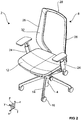
- the Fig. 1 shows the chair or the office chair 2 in a side view with a view of a sagittal or xz plane S, wherein a corresponding Cartesian coordinate system parallel to the seat of the seat part 12 xy-plane or transverse plane T and parallel to the starting position of the backrest 10 Z axis has.
- the x-axis is oriented substantially along the longitudinal sides of the seat surface and the y-axis substantially along the broad sides of the seat surface of the seat part 12.
- the backrest support 8 in a projection onto the sagittal plane S has essentially an L-shaped cross-sectional shape.
- a directed along the x-axis horizontal support arm 18 of the backrest support 8 extends here below the seat part 12.
- the holding arm 18 is at least partially received within the seat support 6.
- the holding arm 18 is in this case by means of two along the x-axis spaced hinges 20 and 22 for a lateral tilting movement of the backrest 10, which means in a frontal or yz plane F laterally or sideways tilt or tilt, designed and set up.
- an axis of rotation D for a lateral tilting movement of the back support 8 or the backrest 10 is thus formed.
- FIGS. 2 to 11 is one or the office chair 2 shown in structurally comparatively detailed representations.
- this embodiment will be described with reference to FIG Fig. 2 to Fig. 11 explained in more detail.
- the Fig. 2 shows the office chair 2 in a perspective view.
- the backrest 10 is in the Fig. 2 not shown, so that a better view of the backrest support 8 is possible.
- the frame-like backrest support 8 has in this embodiment in a projection on the frontal plane F substantially a U-shape.
- the backrest support 8 in this case comprises two in the Ausgansposition along the z-axis oriented vertical U-leg (vertical leg) 26 and directed along the y-axis upper horizontal U-leg (horizontal leg) 28.
- the legs 26, 28 of the backrest support 8 form this essentially a mounting or support frame for the attachable or attached backrest 10th
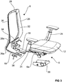
- FIG. 3 the office chair 2 is shown in a perspective exploded view or in the partially disassembled state.
- the seat support 6 has a shell-like housing 30 in which a synchronous mechanism 6a is received in the assembled state.
- two horizontal support arms 18 are formed on the free ends 26a of the vertical leg 26, ie at the lower or seat-side leg ends.
- the support arms 18 and legs 26, 28 form one piece, ie in one piece or monolithic, the backrest support 8.
- the backrest support 8 in this case has a widened to the backrest 10 contact surface 32. Due to the widened contact surface 32, the holding arms 18 and legs 26, 28 have a comparatively small thickness in cross-section.
- the backrest support 8 is preferably made of a flexurally elastic spring steel or plastic material, wherein the comparatively small material thickness of the support arms 18 and legs 26, 28 allows a high flexural elastic deformability, which is the lateral tilting mobility of the backrest 10 beneficial.
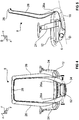
- the vertical legs 26 are slightly inclined in this embodiment in a projection on the sagittal plane S ( Fig. 5 ), wherein the vertical legs 26 in the projection on the frontal plane F ( fig. 4 ) are oriented in particular in the region of the free ends 26 a approximately V-shaped converging towards each other.
- the free ends 26a in this case run slightly backwards, ie away from the seat part 12, so that the backrest support 8 is approximately S-shaped in the projection onto the sagittal plane S.
- the upper S-bend here is formed by the horizontal leg 24 and the vertical legs 26, wherein the lower S-arm is formed by the support arms 18 and the central region connecting the arches of the free ends 26 a.
- Fig. 6 shows a detail of the synchronizing mechanism 6a of the seat support 6 and the lower part of the backrest support 8 in an unassembled state.
- a transverse strut 34 is mounted in the mounted state.
- the cross strut 34 is fastened to a respective attachment point 36 of the vertical leg 26 and the free ends 26 a, so that the transverse strut 34 in the assembled state runs approximately horizontally between the vertical legs 26 at the height of the seat part 12 ( Fig. 4 . Fig. 7 ).
- the transverse strut 34 is preferably made of a flexurally elastic fiberglass material and has with respect to the sagittal plane S, for example, an approximately U-shaped cross-sectional shape. Additionally or alternatively, the fastening of the transverse strut 34 takes place at the attachment points 36 by means of flexible or articulated connection elements.
- the stability of the frame-like backrest support 8 is improved, at the same time the bending elastic deformability or torsion of the vertical leg 26 in the course of a lateral tilting or inclination of the backrest 10 is not adversely affected.
- Fig. 8 individually shown holding arms 18 of in Fig. 7 individually illustrated backrest support 8 have RONd disorder, which means seat or seat carrier side, each having a molded-38.
- the receptacle 38 is part of the designed in this embodiment as a ball joint rotary joint 20.
- the joint socket or ball socket-like receptacle 38 takes in the assembled state a spherical, about hinge-like, extension 40 as a counterpart.
- the extension 40 is - as in particular in Fig. 6 seen - laterally upstanding attached to the seat support 6 and its synchronous mechanism 6a.
- the extension 40 is formed by a spherical (joint) head 42 and an attached, approximately bolt-shaped, (joint) neck 44.
- the extension 40 and the receptacle 38 form in the assembled state, the rotary joint 20, wherein additionally carried by the hinge 20 an attachment of the respective support arm 18 on the seat support 6.
- the holding arm 18 comprises the seat carrier 6 in the assembled state at least in sections on the longitudinal sides of the seat carrier 6 (FIG. Fig. 5 ), so that the spherical head 42 of the extension 40 engages positively in the receptacle 38.
- the Fig. 10 shows a section of a frontal plane F, which passes through the hinge 20.
- the spherical head 42 of the extension 40 is substantially completely in the receptacle 38 of the support arm 18 a.
- the receptacle 38 surrounds the head 42 beyond its equator, so that the ball joint 20 is configured in particular in the manner of a nut joint.
- the mobility of the rotary joint 20 is restricted, which advantageously transfers to the stability of the attachment or the mounting of the support arm 18 on the seat support 6.
- the laterally diametrically opposite projections 40 on the seat support 6 are interconnected.
- the necks 44 of the heads 42 are formed as a common bolt or axle rod 46 passing through the seat support 6 and the synchronizing mechanism 6a, respectively.
- the stability of the projections 40 is improved.
- a roller-like extension or (joint) head 48 is formed on the holding arm 18 in each case.
- the head 48 is thus arranged along the x-axis or in arm longitudinal direction to the receptacle 38 - and thus to the hinge 20 - spaced.
- the roller-shaped head 48 by a trough-shaped (joint) receptacle 50 of a arranged between the support arms 18 rocker 52 is included.
- the roll longitudinal direction of the head 48 is in this case oriented in parallel along the arm longitudinal direction of the respective holding arm 18.
- the head 48 and the receptacle 50 in this case form the rotary joint 22, which is designed in particular as a hinge joint.
- both a ball joint 20 and a hinge joint 22 is arranged along each arm 18, so that along the arm longitudinal direction of the support arms 18 each have an axis of rotation D for the lateral tiltability of the backrest 10 is formed.
- the office chair 2 in this embodiment two below the seat part 12 extending and to each other (horizontally) spaced rotation axes D.
- rocker 52 includes a lower half-shell or rocker part 52a and a vertically alssetzbare upper half-shell or rocker part 52b and at least on the upper rocker part 52b placed and this partially enclosing cover 52c.
- the rocker 52 is arranged crosswise between the retaining arms 18.
- the rocker 52 is in this case flexibly or articulated by means of the receptacles 50 positively secured to the heads 48 of the support arms 18.
- the swinging parts 52a and 52b are sandwiched vertically, that is, stacked along the z-axis.
- the rocker parts 52a and 52b have on the opposite, the holding arms 18 facing narrow sides in each case an approximately quarter-circular half-channel 50a and 50b.
- the half-barrels 50a of the swinging part 52a and the half-barrels 50b of the swinging part 52b form the channel-shaped receiver 50 for the hinge 22.
- the swing member 52a is guided from below to the support arms 18, so that the heads 48 each eino at least partially in the half-inner 50a. Subsequently, the rocker part 52b is placed from above, so that the upper half-pipes 50b are placed on the heads 48.
- the receptacles 50 formed by the half-lips 50a and 50b include the respective heads 48 beyond their respective (roller) equator, so that a secure and positive (bearing-like) attachment of the rocker 52 to the support arms 18 is given.
- the rocker parts 52a and 52b are screwed together vertically.
- two fastening screws 54 are guided from below through recesses 56 of the rocker part 52a and screwed into corresponding threaded bores of the rocker part 52b.
- the rocker 52 is fastened by means of two fastening screws 58 on the seat support 6.
- the fastening screws 58 are for this purpose along the y-axis through recesses 60 of the swing member 52b out and screwed into corresponding threaded holes of the seat support 6 and / or the synchronizing mechanism 6a.
- the cover 52c is finally placed on the swing part 52b.
- a locking or locking means 62 is provided on the backrest support 8 and / or on the seat support 6, which blocks, blocks or at least restricts the lateral tilting mobility of the backrest 10 upon actuation by the user.
- a locking or locking means 62 based on Fig. 12a and the Fig. 12b explained in more detail.
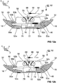
- FIGS. 12a and 12b show in sectional views in each case an alternative embodiment of the rocker 52 with an integrated therein blocking means 62 for blocking the mobility of at least one of the hinge joints 22 of the support arms 18 in a locked state ( Fig. 12a ) and in an unlocked state ( Fig. 12b ).
- the rocker 52 is designed in this embodiment, in particular as a housing for the mechanism of the locking means 62.
- the blocking means 62 is thus in particular configured and designed to block or block the second rotary joint 22, that is to say that rotary joint which is arranged closer to the backrest 10 on the holding arm 18.
- the mobility along the axis of rotation D or along the support arm 18 blocked between the seat carrier-side rotary or ball joint 20 and the backrest support 8.
- the lateral tilting mobility of the backrest support 8 is blocked or at least limited.
- the blocking means 62 has a pull cable 64 for actuation, which is guided by means of a spring element 66 to a lever element 68. this projects at least partially out of the rocker 52 and 52c from the cover.
- the pull cable 64 can be actuated by a user, for example by means of a lever on the seat support 6.
- the lever element 68 mounted pivotably at a central pivot point 70 is coupled at a free end opposite the spring element 66 to a blocking block 72 guided linearly along the y-axis.
- the blocking block 72 is coupled to a spring element 74 designed in particular as a tension spring, which is relaxed in the unlocked state.
- the locking block 72 has a receptacle 76 for a locking pin 78.
- the locking pin 78 is - as in the Figures 12a and 12b seen - pivotally coupled to the (joint) head 48 of the hinge joint 22. This means that the locking pin 78 is pivoted on the head side upon rotation of the hinge joint 22. Thereby pivots the opposite, blocking block-side free end of the locking pin 78 in the unlocked state along the z-axis within the rocker 52.
- the half-lips 50a and 50b each have an unspecified recess, so that a passage opening in the associated receptacle 50 for the Locking pin 78 is formed.
- the blocking-block-side free end of the locking bolt 78 engages in the receptacle 76 of the blocking block 72 in the manner of a pawl and positively.
- the tension spring 74 is tensioned.
- the blockage is released so that the tension spring 74 can relax and moves the lock block 78 out of the blocking position.
- the free end of the locking pin 78 slides out of the receptacle 76, so that the locking pin 78 is free end side movable.
- the spring element 66 in this case has a greater spring strength, ie a greater spring stiffness or spring constant, than the spring element 74.
- a reliable and reliable operation of the locking means 62 is achieved.
- the spring element 74 does not unintentionally relax, and thus releases the blockage.
- the pull cable 64 it is also possible, for example, for the pull cable 64 to have a suitably dimensioned tensile elasticity.
- the blocking means 62 is designed and arranged for blocking or locking both rotary joints 22 on the holding arms 18.
- the hinges 22 are thereby blocked or locked substantially synchronously during an actuation.
Landscapes
- Health & Medical Sciences (AREA)
- Dentistry (AREA)
- General Health & Medical Sciences (AREA)
- Chairs Characterized By Structure (AREA)
- Special Chairs (AREA)
Abstract

Description
- Die Erfindung betrifft ein Sitzmöbel, insbesondere einen Bürostuhl, mit einem Sitzträger für ein horizontales Sitzteil und mit einem Lehenträger für eine vertikale Rückenlehne.
- Ein Bürostuhl ermöglicht es einem darauf sitzendem Benutzer, die Dynamik des Sitzens wesentlich zu beeinflussen. Im Gegensatz zu einem starren Stuhl, welcher lediglich ein statisches beziehungsweise bewegungsloses Sitzen ermöglicht, wird bei einem Bürostuhl aufgrund der integrierten Mechaniken und Anpassungsmöglichkeiten ein sogenanntes dynamisches Sitzen gefördert. Das dynamische beziehungsweise bewegte Sitzen bewirkt insbesondere eine variable Belastung der Rückenmuskulatur, wodurch Verspannungen, Ermüdungen sowie Rückenbeschwerden in Folge längerer Sitzdauern reduziert oder vollständig vermieden werden können.
- Aus der
DE 101 22 946 C1 ist ein Bürostuhl mit einem beweglichen Sitzteil und mit einer beweglichen Rückenlehne bekannt, wobei das Sitzteil und die Rückenlehne mittels einer sogenannten Synchronmechanik gekoppelt sind. Die Synchronmechanik ermöglicht eine synchrone Bewegung des Sitzteils beziehungsweise der Sitzfläche und der Rückenlehne zueinander, wenn die Rückenlehne aus einer im Wesentlichen vertikalen Aufrechtposition (Ausgangsposition) in Folge einer Krafteinwirkung vermittels des Benutzers nach hinten geneigt wird. Die dadurch ermöglichte Schwenk- oder Kippbewegung beschränkt sich bei derartigen Synchronmechaniken in der Regel auf eine Vorwärts- und Rückwärtsneigung (Wippmechanik). - Der aus der
WO 98/48670 A1 - Aus der
DE 10 2007 002 284 A1 ist es bekannt, eine seitliche Schwenkbewegung der Rückenlehne des Stuhles mittels jeweils zweier über Tragarme paarweise verbundene sowie im unteren Bereich der Rückenlehne und im vorderen Bereich des Sitzteils angeordnete Kugelgelenke zu realisieren. - In der
DE 10 2011 104 972 B4 ist ein Bürostuhl beschrieben, bei welchem die laterale Kippbewegung mittels zweier lateral biegeelastischer und/oder angelenkter Tragarme des Lehnenträgers realisierbar ist. - Der Erfindung liegt die Aufgabe zugrunde, ein besonders geeignetes Sitzmöbel, insbesondere einen Bürostuhl, anzugeben. Insbesondere sollen ein möglichst hoher Sitzkomfort sowie eine einfache Anpassung an unterschiedliche Sitzpositionen ermöglicht sein.
- Die Aufgabe wird erfindungsgemäß gelöst durch die Merkmalen des Anspruchs 1. Vorteilhafte Ausgestaltungen und Weiterbildungen sind Gegenstand der Unteransprüche.
- Das insbesondere als ein Bürostuhl ausgeführte Sitzmöbel weist einen Sitzträger für ein horizontales Sitzteil und einen Lehnenträger für eine vertikale Rückenlehne auf. Der insbesondere rahmenartige Lehnenträger weist im Wesentlichen eine U-Form auf, wobei zwei vertikale U-Schenkel (Vertikalschenkel) mittels eines horizontalen oberen U-Schenkels (Horizontalschenkel) verbunden oder gekoppelt sind.
- Die Rückenlehne des Sitzmöbels ist lateral beziehungsweise seitlich oder seitwärts kippbeweglich. Bezogen auf eine Körperachse eines Benutzers erfolgt diese Kippbewegung somit in einer Frontalebene, das bedeutet, aus einer vertikalen Ausgangsposition in Richtung quer zu einer vorzugsweise ebenfalls vorgesehenen Vorwärts- und Rückwärtsneigung in einer Sagittalebene des Benutzers.
- Zu diesem Zwecke sind entlang mindestens einer unterhalb des Sitzteils verlaufenden Drehachse ein erstes Drehgelenk und ein zweites Drehgelenk zur lateralen Kippbeweglichkeit der Rückenlehne gegenüber dem Sitzträger vorgesehen. Das erste und zweite Drehgelenk sind hierbei entlang der Drehachse zueinander beabstandet angeordnet. Im Gegensatz zum Stand der Technik ist somit ein zusätzliches Drehgelenk entlang der Drehachse unterhalb des Sitzteils vorgesehen, wobei die zueinander beabstandeten Drehgelenke vorzugsweise jeweils nicht federbelastet sind.
- Dadurch ist auf konstruktiv einfache Art und Weise eine besonders einfache Anpassung insbesondere hinsichtlich lateral verkippter Sitzpositionen realisiert, wodurch ein verbessertes dynamisches Sitzen ermöglicht ist. Dies überträgt sich in der Folge vorteilhaft auf einen erhöhten Sitzkomfort, sodass ein besonders geeignetes Sitzmöbel, insbesondere hinsichtlich längerer Sitzdauern, realisiert ist.
- Bezogen auf ein kartesisches Koordinatensystem, bei welchem das horizontale Sitzteil beziehungsweise dessen Sitzfläche in der xy-Ebene liegt und sich die Rückenlehne in z-Richtung erstreckt, sind die vertikalen U-Schenkel des Lehnenträgers im Wesentlichen parallel zur z-Richtung orientiert. Die vertikalen U-Schenkel verlaufen im Wesentlichen ausgehend von dem sich unterhalb des Sitzteils befindlichen Sitzträgers nach oben. Der horizontale U-Schenkel ist hierbei geeigneterweise etwa im mittleren oder oberen Bereich der Rückenlehne und vorzugsweise auf deren Rückseite angeordnet. Unter einer derartigen U-Form des Lehnenträgers sind auch etwa V-förmige oder trapezförmige Ausgestaltungen zu verstehen, bei welchen die vertikalen U-Schenkel nicht vollständig parallel zueinander ausgerichtet sind, sondern zumindest abschnittsweise unter einem Winkel geneigt zueinander verlaufen.
- In einer geeigneten Ausführung ist zur Befestigung oder Halterung des Lehnenträgers an dem Sitzträger vorgesehen, dass die vertikalen U-Schenkel an deren sitzseitigen Freienden horizontal gerichtete und unterhalb des Sitzteils verlaufende Haltearme aufweisen, welche den Sitzträger zumindest abschnittsweise seitlich umgreifen, also den Sitzträger zumindest teilweise seitlich flankieren. Durch die nachfolgend auch als Ausleger-, Befestigungs- oder Trägerarme bezeichneten Haltearme weist der Lehnenträger in einer Projektion auf eine xz-Ebene beziehungsweise Sagittalebene eines Benutzers eine etwa L-förmige Kontur auf. Der vertikale L-Schenkel ist hierbei durch die vertikalen U-Schenkel und der horizontale L-Schenkel durch die Haltearme gebildet.
- Der durch die Haltearme und U-Schenkel gebildete Lehnenträger ist in einer möglichen Ausführungsform vorzugsweise einteilig oder einstückig, das bedeutet monolithisch, aus einem biegeelastisch verformbaren Material, beispielsweise einem Kunststoff- oder Federstahlmaterial, gefertigt. Der Lehnenträger, insbesondere dessen U-Schenkel, weisen hierbei vorzugsweise eine Querschnittsform auf, welche eine biegeelastische Verformung oder Torsion entlang des jeweiligen U-Schenkels ermöglicht und/oder unterstützt. Bei einer lateralen Neigungs- oder Kippbewegung der Rückenlehne erfolgt somit auch eine zumindest geringe Verdrehbewegung der Rückenlehne um eine parallel zu den vertikalen U-Schenkeln orientierte Torsionsachse. Aufgrund der Biegeelastizität wird somit eine Rückstellkraft bewirkt, welche die Rückenlehne zurück in die vertikale Ausgangsposition drängt. Somit ist ein besonders vorteilhaftes und ergonomisches Sitzen, insbesondere hinsichtlich lateraler Kippbewegungen, gewährleistet.
- In einer ebenso möglichen Ausführungsform ist der Lehenträger zusätzlich oder alternativ zu der biegeelastischen Verformbarkeit mit Federelementen gekoppelt, welche eine Rückstellkraft im Zuge einer lateralen Kippbewegung erzeugen oder unterstützen. Dadurch wird gewährleistet, dass die Rückenlehne stets zuverlässig in die Ausgangs- beziehungsweise Aufrechtposition geführt wird.
- Ebenso denkbar ist es jedoch beispielsweise auch, dass zwischen den vertikalen U-Schenkeln und den Haltearmen und/oder zwischen den vertikalen U-Schenkeln und dem horizontalen U-Schenkel flexible oder gelenkige Verbindungselemente vorgesehen sind. Dadurch ist es möglich, die U-Schenkel und/oder die Haltearme (biege-)starr auszuführen, ohne die Kippbeweglichkeit der Rückenlehne nachteilig zu beeinflussen.
- In einer vorteilhaften Weiterbildung ist zwischen den vertikalen U-Schenkeln, insbesondere zwischen deren Haltearmen, eine quer zur Drehachse gerichtete Schwinge angeordnet. Durch die querstrebenartige und horizontal angeordnete Schwinge wird die Stabilität des Lehnenträgers verbessert. Vorzugsweise ist die Schwinge hierbei beweglich oder gelenkig zwischen den Haltearmen positioniert und angebunden.
- In einer möglichen Ausbildung ist die Schwinge aus zwei vertikal übereinander gestapelten Halbschalen gebildet. Dadurch wird die Montage der Schwinge am Lehnenträger vereinfacht.
- Zum Zwecke einer möglichst einfachen und stabilen Montage sind die Halbschalen der Schwinge in einer denkbaren Ausgestaltung miteinander verschraubt. In einer optisch besonders ansehnlichen Weiterbildung ist es hierbei vorgesehen, dass die Verschraubung der Halbschalen mittels einer aufgesetzten Abdeckschale oder einer Abdeckplatte verdeckt beziehungsweise abgedeckt ist.
- In einer zweckmäßigen Ausführung ist die Schwinge an dem Sitzträger befestigt. Hierzu ist die Schwinge beispielsweise an einer lehnenseitigen Stirnseite des Sitzträgers schraubbefestigt. Dadurch ist einerseits eine zuverlässige Befestigung und Halterung des Lehnenträgers am Sitzträger realisiert. Andererseits ist die Beweglichkeit, insbesondere die Kippbeweglichkeit, der Rückenlehne aufgrund der vorzugsweise flexiblen oder gelenkigen Anbindung der Schwinge an den Haltearmen des Lehnenträgers nicht nachteilig beeinflusst.
- Ein zusätzlicher oder weiterer Aspekt der Erfindung sieht vor, dass entlang der Haltearme jeweils ein erstes Drehgelenk und ein zweites Drehgelenk zur lateralen Kippbeweglichkeit der Rückenlehne gegenüber dem Sitzträger vorgesehen sind. Vorzugsweise wird durch die ersten und zweiten Drehgelenke der Haltearme jeweils eine Drehachse zur lateralen Kippbeweglichkeit ausgebildet. Dadurch ist eine besonders vorteilhafte und zuverlässige Anpassung an unterschiedliche Sitzpositionen ermöglicht.
- In einer vorteilhaften Ausführung ist das oder jedes erste Drehgelenk als Kugelgelenk ausgebildet, wobei jeweils ein gelenkkopfartiger Fortsatz des Sitzträgers in eine gelenkpfannenartige Aufnahme des Haltearms eingreift. Ebenso denkbar ist eine Ausbildung der Kugelgelenke, bei welchem die Aufnahmen in den Sitzträger und die Fortsätze an den Haltearmen angeformt sind. Das erste Drehgelenk ist hierbei vorzugsweise im Bereich des Freiendes des jeweiligen Haltearms, das bedeutet an dem den U-Schenkeln beziehungsweise der Rückenlehne abgewandten Armende, angeordnet. Dadurch ist ein besonders dynamisches Sitzen gewährleistet.
- In einer bevorzugten Weiterbildung ist das oder jedes zweite Drehgelenk als ein Scharniergelenk ausgebildet, wobei die Haltearme jeweils einen walzenartigen Fortsatz aufweisen, welche jeweils von einer rinnenartigen Aufnahme der Schwinge umfasst sind. Ebenso denkbar ist auch die kinematische Umkehrung mit an der Schwinge angeformten Fortsätzen und Aufnahmen der Haltearme.
- In einer denkbaren alternativen Ausgestaltungsform ist das oder jedes erste Drehgelenk als Scharniergelenk und das oder jedes zweite Drehgelenk als Kugelgelenk ausgebildet. Ebenso denkbar sind Ausgestaltungsformen, in welchen sowohl die ersten als auch die zweiten Drehgelenke als Scharniergelenke oder Kugelgelenke ausgeführt sind.
- In einer bevorzugten Ausführung sind geeigneterweise betätigbare Sperrmittel beispielsweise im Bereich der Rückenlehne und/oder des Sitzträgers vorgesehen, welche es einem Benutzer ermöglichen, auf Wunsch die seitliche oder laterale Kippbeweglichkeit des Lehnenträgers beziehungsweise der Rückenlehne zu sperren beziehungsweise zu blockieren oder zu arretieren oder zumindest einzuschränken.
- In einer geeigneten Weiterbildung ist das Sperrmittel zur Sperrung der Drehbeweglichkeit des oder jedes zweiten Drehgelenks ausgebildet. Das zweite Drehgelenk ist entlang der Drehachse beziehungsweise entlang des Haltearms vorzugsweise näher an dem Lehnenträger beziehungsweise der Rückenlehne angeordnet als das erste Drehgelenk. Dadurch wird die laterale Kippbeweglichkeit bei einer Blockade des zweiten Drehgelenks zuverlässig gehemmt, zumindest eingeschränkt oder gesperrt. Hierbei ist es möglich, dass beide zweiten Drehgelenke im Wesentlichen synchron gesperrt werden. Zur Blockade der lateralen Kippbeweglichkeit ist jedoch die Sperrung auch nur eines der beiden zweiten Drehgelenke ausreichend.
- In einer zweckmäßigen Ausbildung ist das Sperrmittel in der Schwinge angeordnet. Die Schwinge ist hierbei insbesondere als ein Gehäuse für den Mechanismus des Sperrmittels ausgeführt. Das zweite Drehgelenk ist hierbei schwenkfest mit einem Sperrbolzen gekoppelt, welcher freiendseitig in einen formschlüssigen Eingriff mit einem federbelasteten Sperrblock bringbar ist. Der Sperrblock ist hierbei geeigneterweise bei einer Betätigung des Sperrmittels bewegbar, sodass der Eingriff beziehungsweise der Formschluss zwischen dem Sperrbolzen und dem Sperrblock reversibel lösbar und herstellbar ist. Dadurch ist eine besonders zuverlässige und betriebssichere Einschränkung der lateralen Kippbeweglichkeit des Lehnenträgers realisiert.
- Nachfolgend sind Ausführungsbeispiele der Erfindung anhand einer Zeichnung näher erläutert. Darin zeigen in vereinfachten und schematischen Darstellungen:
- Fig. 1
- in einer Seitenansicht einen Bürostuhl als Sitzmöbel mit einem Sitzträger für ein Sitzteil (Sitzfläche) und mit einem Lehnenträger einer lateral neigbaren Rückenlehne,
- Fig. 2
- in einer perspektivischen Ansicht den Bürostuhl in einer zweiten Ausführungsform,
- Fig. 3
- in einer Explosionsdarstellung den Sitzträger und den Lehnenträger,
- Fig. 4
- in einer Rückansicht den Sitzträger und den Lehnenträger des Bürostuhls,
- Fig. 5
- in einer Seitenansicht den Sitzträger und den Lehnenträger,
- Fig. 6
- in perspektivischer Ansicht ausschnittsweise den Sitzträger und den Lehnenträger in einer Explosionsdarstellung,
- Fig. 7
- in einer perspektivischen Ansicht den Lehnenträger,
- Fig. 8
- in einer perspektivischen Ansicht ausschnittsweise einen Haltearm des Lehnenträgers,
- Fig. 9
- in einer Explosionsdarstellung eine Schwinge des Lehnenträgers,
- Fig. 10
- in einer Schnittdarstellung Kugelgelenke zwischen den Sitzträger und den Haltearmen,
- Fig. 11
- in einer Schnittdarstellung Scharniergelenke zwischen den Haltearmen und der Schwinge, und
- Fig. 12a, 12b
- in einer Schnittdarstellung ein Sperrmittel der Schwinge.
- Einander entsprechende Teile und Größen sind in allen Figuren stets mit den gleichen Bezugszeichen versehen.
- Das in der
Fig. 1 als Bürostuhl ausgebildete Sitzmöbel 2 umfasst einen fest mit einem Standfuß (Fußkreuz) 4 verbundenen Sitzträger 6, welcher über einen Lehnenträger 8 mit einer Rückenlehne 10 gekoppelt ist. In den Sitzträger 6 ist vorzugsweise eine sogenannte Synchronmechanik integriert, welche eine synchrone Bewegung eines auf dem Sitzträger 6 angeordneten Sitzteils (Sitz, Sitzfläche) 12 mit der Rückenlehne 10 ausführt, wenn diese aus der dargestellten vertikalen Ausgangsposition (Aufrechtposition) in eine nach hinten geneigte Position ausgelenkt wird. - Der Sitzträger 6 und damit das Sitzteil 12 sowie die über den Lehnenträger 8 mit dem Sitzträger 6 verbundene Rückenlehne 10 sind mit dem Standfuß 4, der beispielsweise drei, vier oder fünf radial verlaufende Arme 14 mit endseitig schwenkbar befestigten Stuhlrollen 16 aufweist, drehbar verbunden beziehungsweise gekoppelt. Beispielhaft sind in den Figuren lediglich ein Arm 14 und eine Stuhlrolle 16 mit einem Bezugszeichen versehen.
- Die
Fig. 1 zeigt das Sitzmöbel beziehungsweise den Bürostuhl 2 in einer Seitenansicht mit Blick auf eine Sagittal- oder xz-Ebene S, wobei ein entsprechendes kartesisches Koordinatensystem eine zu der Sitzfläche des Sitzteils 12 parallele xy-Ebene beziehungsweise Transversalebene T und eine zu der Ausgangsposition der Rückenlehne 10 parallele z-Achse aufweist. Die x-Achse ist hierbei im Wesentlichen entlang der Längsseiten der Sitzfläche und die y-Achse im Wesentlichen entlang der Breitseiten der Sitzfläche des Sitzteils 12 orientiert. - Wie in der Seitenansicht der
Fig. 1 vergleichsweise deutlich ersichtlich weist der Lehnenträger 8 in einer Projektion auf die Sagittalebene S im Wesentlichen eine L-förmige Querschnittsform auf. Ein entlang der x-Achse gerichteter horizontaler Haltearm 18 des Lehnenträgers 8 erstreckt sich hierbei unterhalb des Sitzteils 12. In dem Ausführungsbeispiel derFig. 1 ist der Haltearm 18 zumindest teilweise innerhalb des Sitzträgers 6 aufgenommen. - Wie in der
Fig. 1 strichliniert dargestellt, ist der Haltearm 18 hierbei mittels zweier entlang der x-Achse zueinander beabstandete Drehgelenke 20 und 22 für eine laterale Kippbewegung der Rückenlehne 10, das bedeutet in einer Frontal- oder yz-Ebene F seitlich oder seitwärts gerichtete Neigung oder Verkippung, ausgestaltet und eingerichtet. Entlang der Verbindungslinie zwischen den Drehgelenken 20 und 22 ist somit eine Drehachse D für eine laterale Kippbewegung des Lehenträgers 8 beziehungsweise der Rückenlehne 10 ausgebildet. - In den
Figuren 2 bis 11 ist ein oder der Bürostuhl 2 in konstruktiv vergleichsweise detaillierten Darstellungen gezeigt. Nachfolgend wird diese Ausführungsform anhand derFig. 2 bis Fig. 11 näher erläutert. - Die
Fig. 2 zeigt den Bürostuhl 2 in einer perspektivischen Darstellung. An den Sitzträger 6 des Bürostuhls 2 sind in diesem Ausführungsbeispiel zwei Armlehnen 24 befestigt, welche dem Sitzteil 12 seitlich in vertikaler Richtung emporstehen. Die Rückenlehne 10 ist in derFig. 2 nicht dargestellt, sodass ein besserer Blick auf den Lehnenträger 8 ermöglicht ist. Der rahmenartige Lehnenträger 8 weist in dieser Ausführungsform in einer Projektion auf die Frontalebene F im Wesentlichen eine U-Form auf. Der Lehnenträger 8 umfasst hierbei zwei in der Ausgansposition entlang der z-Achse orientierte vertikale U-Schenkel (Vertikalschenkel) 26 und einen entlang der y-Achse gerichteten oberen horizontalen U-Schenkel (Horizontalschenkel) 28. Die Schenkel 26, 28 des Lehnenträgers 8 bilden hierbei im Wesentlichen einen Befestigungs- oder Tragrahmen für die daran anbringbare oder angebrachte Rückenlehne 10. - In der
Fig. 3 ist der Bürostuhl 2 in einer perspektivischen Explosionsdarstellung bzw. im teilweise auseinander genommenen Zustand gezeigt. Der Sitzträger 6 weist ein schalenartiges Gehäuse 30 auf, in welchem im Montagezustand eine Synchronmechanik 6a aufgenommen ist. Wie in der perspektivischen Explosionsdarstellung derFig. 3 vergleichsweise deutlich ersichtlich ist, sind an den Freienden 26a der Vertikalschenkel 26, also an den unteren beziehungsweise sitzseitigen Schenkelenden, zwei horizontale Haltearme 18 angeformt. - Die Haltearme 18 und Schenkel 26, 28 bilden einteilig, also einstückig oder monolithisch, den Lehnenträger 8. Der Lehnenträger 8 weist hierbei eine zur Rücklehne 10 verbreiterte Anlagefläche 32 auf. Durch die verbreiterte Anlagefläche 32 weisen die Haltearme 18 und Schenkel 26, 28 im Querschnitt eine vergleichsweise geringe Dicke auf. Der Lehnenträger 8 ist vorzugsweise aus einem biegeelastischen Federstahl- oder Kunststoffmaterial hergestellt, wobei die vergleichsweise geringe Materialdicke der Haltearme 18 und Schenkel 26, 28 eine hohe biegeelastische Verformbarkeit ermöglicht, welche der lateralen Kippbeweglichkeit der Rückenlehne 10 zuträglich ist.
- Aufgrund des U-förmigen Verlaufs der Schenkel 26, 28 entlang der durch die Schenkelbreite definierte Anlagefläche 32 auf das Sitzteil 12 zu bewegt sich die daran angeordnete (nicht näher dargestellte) Rückenlehne 10 in Folge einer seitwärts beziehungsweise lateral gerichteten Kraft auf einer Kreisbahn beziehungsweise entlang eines Kreisbogens parallel zur Frontalebene F. Der Radius dieser kreisbogenförmigen Lehnenbewegung, der an die Bogenkontur der der Rückenlehne 10 zugewandten Sitzteilkante angepasst sein kann, ist derart eingestellt, bemessen oder ausgelegt, dass die sich seitwärts neigende Rückenlehne 10 weder in das Sitzteil 12 spürbar hineinläuft, noch sich von dieser spürbar wegbewegt.
- Wie anhand der
Fig. 4 und derFig. 5 vergleichsweise deutlich ersichtlich ist, sind die Vertikalschenkel 26 in diesem Ausführungsbeispiel in einer Projektion auf die Sagittalebene S leicht geneigt (Fig. 5 ), wobei die Vertikalschenkel 26 in der Projektion auf die Frontalebene F (fig. 4 ) insbesondere im Bereich der Freienden 26a etwa V-förmig aufeinander zulaufend orientiert sind. Die Freienden 26a verlaufen hierbei leicht nach hinten geneigt, also von dem Sitzteil 12 weg, sodass der Lehnenträger 8 in der Projektion auf die Sagittalebene S etwa S-förmig geformt ist. - Der obere S-Bogen ist hierbei von dem Horizontalschenkel 24 und den Vertikalschenkeln 26 gebildet, wobei der untere S-Bogen durch die Haltearme 18 und der die Bögen verbindende Mittelbereich von den Freienden 26a gebildet ist. Dadurch wird die Biegeelastizität des Lehnenträgers 8, auch hinsichtlich einer Vorwärts- und Rückwärtskippbewegung, verbessert.
- Anhand der
Fig. 6 ist die laterale Kippbeweglichkeit der Rückenlehne 10 beziehungsweise des Lehnenträgers 8 näher erläutert. DieFig. 6 zeigt ausschnittsweise die Synchronmechanik 6a des Sitzträgers 6 sowie den unteren Teil des Lehnenträgers 8 in einem nicht montierten Zustand. - Im Bereich des unteren S-Bogens, das bedeutet in dem Übergangsbereich der Freienden 26a zu den Haltearmen 18, ist im montierten Zustand eine Querstrebe 34 angebracht. Die Querstrebe 34 ist an jeweils einem Befestigungspunkt 36 der Vertikalschenkel 26 beziehungsweise deren Freienden 26a befestigbar, sodass die Querstrebe 34 im Montagezustand etwa auf Höhe des Sitzteils 12 horizontal zwischen den Vertikalschenkeln 26 verläuft (
Fig. 4 ,Fig. 7 ). - Die Querstrebe 34 ist vorzugsweise aus einem biegeelastischen Glasfasermaterial gefertigt und weist hinsichtlich der Sagittalebene S beispielsweise eine etwa U-förmige Querschnittsform auf. Zusätzlich oder alternativ erfolgt die Befestigung der Querstrebe 34 an den Befestigungspunkten 36 mittels flexibler oder gelenkiger Verbindungselemente. Durch die Querstrebe 34 wird die Stabilität des rahmenartigen Lehnenträgers 8 verbessert, wobei gleichzeitig die biegeelastische Verformbarkeit oder Torsion der Vertikalschenkel 26 im Zuge einer lateralen Verkippung oder Neigung der Rückenlehne 10 nicht nachteilig eingeschränkt wird.
- Die in
Fig. 8 einzeln dargestellten Haltearme 18 des inFig. 7 einzeln dargestellten Lehnenträgers 8 weisen freiendseitig, das bedeutet sitz- beziehungsweise sitzträgerseitig, jeweils eine angeformte Aufnahme 38 auf. Die Aufnahme 38 ist Teil des in dieser Ausführung als Kugelgelenk ausgestalteten Drehgelenks 20. Die gelenkpfannen- oder kugelpfannenartige Aufnahme 38 nimmt im Montagezustand einen kugelförmigen, etwa gelenkkopfartigen, Fortsatz 40 als Gegenstück auf. Der Fortsatz 40 ist - wie insbesondere inFig. 6 ersichtlich - seitlich emporstehend an den Sitzträger 6 beziehungsweise dessen Synchronmechanik 6a angebracht. - Der Fortsatz 40 ist durch einen kugelförmigen (Gelenk-)Kopf 42 und einen daran befestigten, etwa bolzenförmigen, (Gelenk-)Hals 44 gebildet.
- Der Fortsatz 40 und die Aufnahme 38 bilden im Montagezustand das Drehgelenk 20, wobei durch das Drehgelenk 20 zusätzlich eine Befestigung des jeweiligen Haltearms 18 an dem Sitzträger 6 erfolgt. Hierzu umfasst der Haltearm 18 den Sitzträger 6 im Montagezustand zumindest abschnittsweise an den Längsseiten des Sitzträgers 6 (
Fig. 5 ), sodass der kugelförmige Kopf 42 des Fortsatzes 40 formschlüssig in die Aufnahme 38 eingreift. - Die
Fig. 10 zeigt einen Schnitt einer Frontalebene F, welcher durch das Drehgelenk 20 verläuft. Wie in der Schnittdarstellung derFig. 10 vergleichsweise deutlich ersichtlich ist, liegt der kugelförmige Kopf 42 des Fortsatzes 40 im Wesentlichen vollständig in der Aufnahme 38 des Haltearms 18 ein. Insbesondere umschließt die Aufnahme 38 den Kopf 42 über dessen Äquator hinaus, sodass das Kugelgelenk 20 insbesondere nach Art eines Nussgelenks ausgestaltet ist. Dadurch wird die Beweglichkeit des Drehgelenks 20 eingeschränkt, was sich vorteilhaft auf die Stabilität der Befestigung oder der Halterung des Haltearms 18 am Sitzträger 6 überträgt. - Wie in der
Fig. 10 dargestellt, sind die am Sitzträger 6 seitlich diametral gegenüberliegenden Fortsätze 40 miteinander verbunden. Insbesondere sind die Hälse 44 der Köpfe 42 als ein gemeinsamer, den Sitzträger 6 beziehungsweise die Synchronmechanik 6a durchsetzender Bolzen oder Achsenstab 46 ausgebildet. Dadurch wird die Stabilität der Fortsätze 40 verbessert. - Zwischen der Aufnahme 38 und dem Freiende 26a ist jeweils ein walzenartiger Fortsatz oder (Gelenk-)Kopf 48 an den Haltearm 18 angeformt. Der Kopf 48 ist somit entlang der x-Achse beziehungsweise in Armlängsrichtung zu der Aufnahme 38 - und somit zum Drehgelenk 20 - beabstandet angeordnet.
- Im Montagezustand (
Fig. 11 ) wird der walzenförmige Kopf 48 von einer rinnenförmigen (Gelenk-)Aufnahme 50 einer zwischen den Haltearmen 18 angeordneten Schwinge 52 umfasst. Die Walzenlängsrichtung des Kopfes 48 ist hierbei parallel entlang der Armlängsrichtung des jeweiligen Haltearms 18 orientiert. Der Kopf 48 und die Aufnahme 50 bilden hierbei das Drehgelenk 22, welches insbesondere als ein Scharniergelenk ausgebildet ist. - Somit ist entlang jedes Haltearmes 18 sowohl ein Kugelgelenk 20 als auch ein Scharniergelenk 22 angeordnet, sodass entlang der Armlängsrichtung der Haltearme 18 jeweils eine Drehachse D für die laterale Kippbeweglichkeit der Rückenlehne 10 gebildet ist. Mit anderen Worten weist der Bürostuhl 2 in diesem Ausführungsbeispiel zwei unterhalb des Sitzteils 12 verlaufende und zueinander (horizontal) beabstandete Drehachsen D auf.
- Die in
Fig. 9 einzeln dargestellte Schwinge 52 umfasst eine untere Halbschale oder Schwingenteil 52a und eine hierauf vertikal aufsetzbare obere Halbschale oder Schwingenteil 52b sowie eine zumindest auf das obere Schwingenteil 52b aufsetzbare und dieses abschnittsweise umgreifende Abdeckschale 52c. Im Montagezustand ist die Schwinge 52 querstrebenartig zwischen den Haltearmen 18 angeordnet. Die Schwinge 52 ist hierbei flexibel beziehungsweise gelenkig mittels der Aufnahmen 50 formschlüssig an den Köpfen 48 der Haltearme 18 befestigt. - Im Montagezustand sind die Schwingenteile 52a und 52b sandwichartig vertikal, das bedeutet entlang der z-Achse, übereinander gestapelt. Die Schwingenteile 52a und 52b weisen an den gegenüberliegenden, den Haltearmen 18 zugewandten Schmalseiten jeweils eine etwa viertelkreisförmige Halbrinne 50a beziehungsweise 50b auf. Im gestapelten oder zusammengesetzten Zustand bilden die Halbrinnen 50a des Schwingenteils 52a und die Halbrinnen 50b des Schwingenteils 52b die rinnenförmige Aufnahme 50 für das Scharnier- beziehungsweise Drehgelenk 22.
- Zur Montage wird das Schwingenteil 52a von unten an die Haltearme 18 geführt, sodass die Köpfe 48 jeweils zumindest teilweise in den Halbrinnen 50a einliegen. Anschließend wird von oben das Schwingenteil 52b aufgesetzt, sodass die oberen Halbrinnen 50b auf die Köpfe 48 aufgesetzt werden. Wie in der in
Fig. 11 gezeigten Schnittdarstellung durch die Scharniergelenke 22 deutlich ersichtlich ist, umfassen die durch die Halbrinnen 50a und 50b gebildeten Aufnahmen 50 die jeweiligen Köpfe 48 über ihren jeweiligen (Walzen-)Äquator hinaus, sodass eine sichere und formschlüssige (lagerartige) Befestigung der Schwinge 52 an den Haltearmen 18 gegeben ist. - Zur Montage der Schwinge 52 werden die Schwingenteile 52a und 52b miteinander vertikal verschraubt. Hierzu werden zwei Befestigungsschrauben 54 von unten durch Aussparungen 56 des Schwingenteils 52a geführt und in entsprechenden Gewindebohrungen des Schwingenteils 52b eingedreht. Anschließend wird die Schwinge 52 mittels zweier Befestigungsschrauben 58 an dem Sitzträger 6 befestigt. Die Befestigungsschrauben 58 werden hierzu entlang der y-Achse durch Aussparungen 60 des Schwingenteils 52b geführt und in entsprechenden Gewindebohrungen des Sitzträgers 6 und/oder der Synchronmechanik 6a geschraubt. Zur optisch ansehnlichen Abdeckung der Schraubenköpfe der Befestigungsschrauben 58 wird abschließend die Abdeckschale 52c auf das Schwingenteil 52b aufgesetzt.
- Aufgrund der formschlüssigen Halterung mittels des Scharniergelenks 22 erfolgt im Zuge der Schraubbefestigung der Schwinge 52 am Sitzträger 12 somit ebenfalls eine Befestigung des Lagerträgers 8 am Sitzträger 12. Mit anderen Worten ist der Lagerträger 8 einerseits mittels der Kugelgelenke 20 und andererseits mittels der Schwinge 52 an dem Sitzteil 12 des Bürostuhls 2 befestigt. Dadurch ist eine zuverlässige und betriebssichere Befestigung oder Halterung der Rückenlehne 10 an dem Sitzträger 12 realisiert. Gleichzeitig wird die biegeelastische Verformbarkeit des Lehnenträgers 8 nicht nachteilig beeinflusst, sodass eine laterale Kippbeweglichkeit hierdurch nicht eingeschränkt wird.
- Vorzugsweise ist ein Arretier- oder Sperrmittel 62 am Lehnenträger 8 und/oder an dem Sitzträger 6 vorgesehen, welches bei einer Betätigung durch den Benutzer die laterale Kippbeweglichkeit der Rückenlehne 10 blockiert, sperrt oder zumindest einschränkt. Nachfolgend ist ein Ausführungsbeispiel des Sperrmittels 62 anhand der
Fig. 12a und derFig. 12b näher erläutert. - Die
Figuren 12a und 12b zeigen in Schnittdarstellungen jeweils eine alternative Ausführungsform der Schwinge 52 mit einem darin integrierten Sperrmittel 62 zur Sperrung der Beweglichkeit zumindest eines der Scharniergelenke 22 der Haltearme 18 in einem gesperrten Zustand (Fig. 12a ) und in einem entsperrten Zustand (Fig. 12b ). Die Schwinge 52 ist in dieser Ausführungsform insbesondere als ein Gehäuse für den Mechanismus des Sperrmittels 62 ausgeführt. - Das Sperrmittel 62 ist somit insbesondere dafür eingerichtet und ausgestaltet, das zweite Drehgelenk 22, also dasjenige Drehgelenk, welches am Haltearm 18 näher an der Rückenlehne 10 angeordnet ist, zu blockieren oder zu sperren. Somit ist die Beweglichkeit entlang der Drehachse D beziehungsweise entlang dem Haltearm 18 zwischen dem sitzträgerseitigen Dreh- oder Kugelgelenk 20 und dem Lehnenträger 8 blockiert. Dadurch wird die laterale Kippbeweglichkeit des Lehnenträgers 8 blockiert oder zumindest eingeschränkt.
- Das Sperrmittel 62 weist zur Betätigung ein Zugseil 64 auf, welches mittels eines Federelements 66 an ein Hebelelement 68 geführt ist. dieses ragt zumindest teilweise aus der Schwinge 52 beziehungsweise aus der Abdeckschale 52c heraus. Das Zugseil 64 ist beispielsweise mittels eines Hebels am Sitzträger 6 von einem Benutzer betätigbar. Das an einem mittigen Drehpunkt 70 schwenkbar gelagerte Hebelelement 68 ist an einem dem Federelement 66 gegenüberliegenden Freiende mit einem entlang der y-Achse linear geführten Sperrblock 72 gekoppelt.
- Der Sperrblock 72 ist mit einem insbesondere als Zugfeder ausgeführten Federelement 74 gekoppelt, welches im entsperrten Zustand entspannt ist. Der Sperrblock 72 weist eine Aufnahme 76 für einen Sperrbolzen 78 auf.
- Der Sperrbolzen 78 ist - wie in den
Figuren 12a und 12b ersichtlich - schwenkfest mit dem (Gelenk-)Kopf 48 des Scharniergelenks 22 gekoppelt. Dies bedeutet, dass der Sperrbolzen 78 bei einer Drehung des Scharniergelenks 22 kopfseitig verschwenkt wird. Dadurch schwenkt das gegenüberliegende, sperrblockseitige Freiende des Sperrbolzens 78 im nicht gesperrten Zustand entlang der z-Achse innerhalb der Schwinge 52. Die Halbrinnen 50a und 50b weisen hierbei jeweils eine nicht näher bezeichnete Aussparung auf, so dass eine Durchführöffnung in der zugeordneten Aufnahme 50 für den Sperrbolzen 78 ausgebildet ist. - Im gesperrten Zustand greift das sperrblockseitige Freiende des Sperrbolzens 78 sperrklinkenartig und formschlüssig in die Aufnahme 76 des Sperrblocks 72 ein. Im gesperrten Zustand ist die Zugfeder 74 gespannt. Beim erneuten Betätigen des Zugseils 64 wird die Blockade gelöst, sodass die Zugfeder 74 entspannen kann und den Sperrblock 78 aus der blockierenden Stellung bewegt. Dadurch gleitet das Freiende des Sperrbolzens 78 aus der Aufnahme 76 hinaus, sodass der Sperrbolzen 78 freiendseitig bewegbar ist.
- In einer geeigneten Dimensionierung weist das Federelement 66 hierbei eine größere Federstärke, also eine größere Federhärte oder Federkonstante, als das Federelement 74 auf. Dadurch wird eine zuverlässige und betriebssichere Betätigung des Sperrmittels 62 erreicht. Insbesondere wird verhindert, dass sich das Federelement 74 nicht ungewollt entspannt, und somit die Blockierung löst. Anstelle des Federelements 66 ist es beispielsweise ebenso möglich, dass das Zugseil 64 eine entsprechend dimensionierte Zugelastizität aufweist.
- Die Erfindung ist nicht auf die vorstehend beschriebenen Ausführungsbeispiele beschränkt. Vielmehr können auch andere Varianten der Erfindung von dem Fachmann hieraus abgeleitet werden, ohne den Gegenstand der Erfindung zu verlassen. Insbesondere sind ferner alle im Zusammenhang mit den Ausführungsbeispielen beschriebenen Einzelmerkmale auch auf andere Weise miteinander kombinierbar, ohne den Gegenstand der Erfindung zu verlassen.
- So ist es beispielsweise denkbar, dass zur Verbesserung der Rückstellkraft bei einem ausgelenkten Lehnenträger 8, die biegeelastische Verformbarkeit des Lehnenträgers 8 mittels zusätzlicher Federelemente unterstützt wird.
- Ebenso ist es beispielsweise denkbar, dass das Sperrmittel 62 zur Blockierung oder Arretierung beider Drehgelenke 22 an den Haltearmen 18 ausgebildet und eingerichtet ist. Vorzugsweise werden die Drehgelenke 22 hierbei bei einer Betätigung im Wesentlichen synchron blockiert oder gesperrt.
-
- 2
- Sitzmöbel/Bürostuhl
- 4
- Standfuß/Fußkreuz
- 6
- Sitzträger
- 6a
- Synchronmechanik
- 8
- Lehnenträger
- 10
- Rückenlehne
- 12
- Sitzteil
- 14
- Arm
- 16
- Stuhlrolle
- 18
- Haltearm
- 20
- Drehgelenk/Kugelgelenk
- 22
- Drehgelenk/Scharniergelenk
- 24
- Armlehne
- 26
- U-Schenkel/Vertikalschenkel
- 26a
- Freiende
- 28
- U-Schenkel/Horizontalschenkel
- 30
- Gehäuse
- 32
- Anlagefläche
- 34
- Querstrebe
- 36
- Befestigungspunkt
- 38
- Aufnahme
- 40
- Fortsatz
- 42
- Kopf
- 44
- Hals
- 46
- Bolzen/Achsenstab
- 48
- Fortsatz/Kopf
- 50
- Aufnahme
- 50a, 50b
- Halbrinne
- 52
- Schwinge
- 52a, 52b
- Schwingenteil
- 52c
- Abdeckschale
- 54
- Befestigungsschraube
- 56
- Aussparung
- 58
- Befestigungsschraube
- 60
- Aussparung
- 62
- Sperrmittel
- 64
- Zugseil
- 66
- Federelement
- 68
- Hebelelement
- 70
- Drehpunkt
- 72
- Sperrblock
- 74
- Federelement/Zugfeder
- 76
- Aufnahme
- 78
- Sperrbolzen
- x, y, z
- Achse
- S
- Sagittalebene
- F
- Frontalebene
- T
- Transversalebene
- D
- Drehachse
Claims (13)
- Sitzmöbel (2), insbesondere Bürostuhl, mit einem Sitzträger (6) für ein horizontales Sitzteil (12) und mit einem Lehnenträger (8) für eine vertikale Rückenlehne (10),- wobei der Lehnenträger (8) im Wesentlichen U-förmig mit zwei vertikal orientierten U-Schenkeln (26) und mit einem horizontalen oberen U-Schenkel (28) ausgeführt ist,- wobei entlang mindestens einer unterhalb des Sitzteils (12) verlaufenden Drehachse (D) ein erstes Drehgelenk (20) und ein zweites Drehgelenk (22) zur lateralen Kippbeweglichkeit der Rückenlehne (10) gegenüber dem Sitzträger (12) vorgesehen sind, und- wobei das erste und zweite Drehgelenk (20, 22) entlang der Drehachse (D) zueinander beabstandet angeordnet sind.
- Sitzmöbel (2) nach Anspruch 1,
dadurch gekennzeichnet,
dass die vertikalen U-Schenkel (26) an deren sitzseitigen Freienden (26a) horizontal gerichtete und unterhalb des Sitzteils (12) verlaufende Haltearme (18) aufweisen, welche den Sitzträger (12) zumindest abschnittsweise seitlich umgreifen. - Sitzmöbel (2) nach Anspruch 2,
dadurch gekennzeichnet,
dass zwischen den vertikalen U-Schenkeln (26), insbesondere zwischen deren Haltearmen (18), eine quer zur Drehachse (D) gerichtete Schwinge (52) angeordnet ist. - Sitzmöbel (2) nach Anspruch 3,
dadurch gekennzeichnet,
dass die Schwinge (52) aus zwei vertikal übereinander gestapelten Halbschalen (52a, 52b) gebildet ist. - Sitzmöbel (2) nach Anspruch 4,
dadurch gekennzeichnet,
dass die Halbschalen (52a, 52b) der Schwinge (52) miteinander verschraubt sind. - Sitzmöbel (2) nach Anspruch 5,
dadurch gekennzeichnet,
dass die Verschraubung der Halbschalen (52a, 52b) mittels einer aufgesetzten Abdeckschale (52c) verdeckt ist. - Sitzmöbel (2) nach einem der Ansprüche 3 bis 6,
dadurch gekennzeichnet,
dass die Schwinge (52) an dem Sitzträger (12) befestigt ist. - Sitzmöbel (2) nach einem der Ansprüche 2 bis 7,
dadurch gekennzeichnet,
dass entlang der Haltearme (18) jeweils ein erstes Drehgelenk (20) und ein zweites Drehgelenk (22) zur lateralen Kippbeweglichkeit der Rückenlehne (10) gegenüber dem Sitzträger (12) vorgesehen sind. - Sitzmöbel (2) nach einem der Ansprüche 2 bis 8,
dadurch gekennzeichnet,
dass das oder jedes erste Drehgelenk (20) als Kugelgelenk ausgebildet ist, wobei jeweils ein gelenkkopfartiger Fortsatz (40) des Sitzträgers (12) in eine gelenkpfannenartige Aufnahme (38) des Haltearms (18) eingreift. - Sitzmöbel (2) nach einem der Ansprüche 3 bis 9,
dadurch gekennzeichnet,
dass das oder jedes zweite Drehgelenk (22) als Scharniergelenk ausgebildet ist, wobei die Haltearme (18) jeweils einen walzenartigen Fortsatz (48) aufweisen, welche jeweils von einer rinnenartigen Aufnahme (50) der Schwinge (52) umfasst sind. - Sitzmöbel (2) nach einem der Ansprüche 1 bis 10,
dadurch gekennzeichnet,
dass ein betätigbares Sperrmittel (62) zur Sperrung oder Blockierung der lateralen Kippbeweglichkeit des Lehnenträgers (8) vorgesehen ist. - Sitzmöbel (2) nach Anspruch 11,
dadurch gekennzeichnet,
dass das Sperrmittel (62) zur Sperrung der Beweglichkeit des oder jedes zweiten Drehgelenks (22) ausgebildet ist. - Sitzmöbel (2) nach Anspruch 11 oder 12,
dadurch gekennzeichnet,
dass das Sperrmittel (62) in der Schwinge (52) angeordnet ist und einen mit dem zweiten Drehgelenk (22) schwenkfest gekoppelten Sperrbolzen (78) aufweist, welcher in, insbesondere formschlüssigen, Eingriff mit einem federbelasteten Sperrblock (72) bringbar ist.
Priority Applications (1)
| Application Number | Priority Date | Filing Date | Title |
|---|---|---|---|
| PL18153911T PL3354161T3 (pl) | 2017-01-30 | 2018-01-29 | Mebel do siedzenia, zwłaszcza krzesło biurowe |
Applications Claiming Priority (1)
| Application Number | Priority Date | Filing Date | Title |
|---|---|---|---|
| DE202017100480.5U DE202017100480U1 (de) | 2017-01-30 | 2017-01-30 | Sitzmöbel, insbesondere Bürostuhl |
Publications (3)
| Publication Number | Publication Date |
|---|---|
| EP3354161A2 true EP3354161A2 (de) | 2018-08-01 |
| EP3354161A3 EP3354161A3 (de) | 2018-10-17 |
| EP3354161B1 EP3354161B1 (de) | 2020-03-04 |
Family
ID=61074418
Family Applications (1)
| Application Number | Title | Priority Date | Filing Date |
|---|---|---|---|
| EP18153911.5A Active EP3354161B1 (de) | 2017-01-30 | 2018-01-29 | Sitzmöbel, insbesondere bürostuhl |
Country Status (4)
| Country | Link |
|---|---|
| US (1) | US10420423B2 (de) |
| EP (1) | EP3354161B1 (de) |
| DE (1) | DE202017100480U1 (de) |
| PL (1) | PL3354161T3 (de) |
Families Citing this family (8)
| Publication number | Priority date | Publication date | Assignee | Title |
|---|---|---|---|---|
| IT201700057341A1 (it) * | 2017-05-26 | 2018-11-26 | Brado S P A | Dispositivo di regolazione per una sedia con meccanismo oscillante |
| US10702066B2 (en) * | 2018-11-19 | 2020-07-07 | Profim SP. ZO.O | Office chair |
| EP3741258B1 (de) * | 2019-05-20 | 2025-11-05 | BOCK 1 GmbH & Co. KG | Stuhl mit sitzneigemechanik |
| US11051624B1 (en) * | 2020-02-27 | 2021-07-06 | Comfordy Co., Ltd. | Twistable chair backrest frame |
| WO2021237811A1 (zh) * | 2020-05-28 | 2021-12-02 | 安吉德卡办公系统有限公司 | 一种可调节靠背的椅座连接装置 |
| USD1055606S1 (en) * | 2022-02-17 | 2024-12-31 | Viccarbe Habitat, S.L. | Armrest |
| DE202023100146U1 (de) * | 2023-01-12 | 2024-04-16 | Armin Sander | Sitzmöbel |
| USD1107448S1 (en) * | 2023-06-16 | 2025-12-30 | Anji Longbo Furniture Co. Ltd | Chair |
Family Cites Families (15)
| Publication number | Priority date | Publication date | Assignee | Title |
|---|---|---|---|---|
| US148380A (en) * | 1874-03-10 | Improvement in chair-backs | ||
| US2823732A (en) * | 1954-10-26 | 1958-02-18 | John H Humphrey | Adjustable chairs |
| JPS59207112A (ja) * | 1983-05-10 | 1984-11-24 | メ−コ−工業株式会社 | 椅子 |
| DE4235435A1 (de) * | 1992-10-21 | 1994-04-28 | Martin Steifensand Sitzmoebel | Sitzträger für Sitzmöbel |
| US6059363A (en) * | 1997-04-30 | 2000-05-09 | Haworth, Inc. | Chairback with side torsional movement |
| US5909924A (en) | 1997-04-30 | 1999-06-08 | Haworth, Inc. | Tilt control for chair |
| DE10122946C1 (de) | 2001-05-11 | 2003-01-30 | Armin Sander | Stuhl, insbesondere Bürostuhl |
| US7226130B2 (en) | 2002-09-12 | 2007-06-05 | Steelcase Development Corporation | Seating with comfort surface |
| DE102011001811A1 (de) * | 2011-04-05 | 2012-10-11 | Wilkhahn Wilkening + Hahne Gmbh + Co. Kg | Stuhl |
| AT12867U1 (de) * | 2011-05-04 | 2013-01-15 | Eckhard Dipl Ing Hansen | Sitzmöbel |
| DE102011104972B4 (de) | 2011-06-08 | 2015-03-05 | Haworth, Inc. | Sitzmöbel, insbesondere Bürostuhl |
| JP6009891B2 (ja) * | 2011-11-04 | 2016-10-19 | 株式会社岡村製作所 | 椅子 |
| KR20130142520A (ko) * | 2012-06-19 | 2013-12-30 | 에스케이하이닉스 주식회사 | 저항성 메모리 소자 및 그 제조 방법 |
| DE102012107778B4 (de) | 2012-08-23 | 2018-08-16 | Haworth Gmbh | Stuhl, insbesondere Bürostuhl |
| US9167902B1 (en) * | 2014-07-01 | 2015-10-27 | Yung-hua Chen | One-piece office chair in three dimensions |
-
2017
- 2017-01-30 DE DE202017100480.5U patent/DE202017100480U1/de active Active
-
2018
- 2018-01-29 EP EP18153911.5A patent/EP3354161B1/de active Active
- 2018-01-29 PL PL18153911T patent/PL3354161T3/pl unknown
- 2018-01-30 US US15/883,508 patent/US10420423B2/en active Active
Also Published As
| Publication number | Publication date |
|---|---|
| US10420423B2 (en) | 2019-09-24 |
| PL3354161T3 (pl) | 2021-05-04 |
| EP3354161B1 (de) | 2020-03-04 |
| EP3354161A3 (de) | 2018-10-17 |
| US20180213939A1 (en) | 2018-08-02 |
| DE202017100480U1 (de) | 2018-05-03 |
Similar Documents
| Publication | Publication Date | Title |
|---|---|---|
| EP3354161B1 (de) | Sitzmöbel, insbesondere bürostuhl | |
| EP0960586B1 (de) | Stuhl, insbesondere Bürostuhl | |
| DE60110410T2 (de) | Stuhl | |
| EP0377138B1 (de) | Stuhl | |
| DE69400603T2 (de) | Stuhl | |
| DE69316237T2 (de) | Einstellmechanismus für ein in einem sitz integriertes stützelement, welches in vertikaler richtung schwenkbar ist | |
| DE4436145A1 (de) | Sitzmöbel | |
| DE8560028U1 (de) | Stuhl, insbesondere Bürostuhl. | |
| DE202010013146U1 (de) | Schwingsessel | |
| EP3007590A1 (de) | Stuhl | |
| EP0397661A1 (de) | Stuhl, insbesondere arbeits- oder bürostuhl. | |
| DE2623024A1 (de) | Sitzmoebel, insbesondere stuhl mit sitzteil | |
| DE202010017030U1 (de) | Stuhlanordnung mit Mechanismus zum Vermeiden eines übermäßigen Drehens der Rückenlehne | |
| DE1270244B (de) | Stuhl | |
| DE202017104716U1 (de) | Sitzmöbel, insbesondere Bürostuhl, sowie Rückenlehne | |
| DE3634055A1 (de) | Sitzmoebel | |
| DE202011000586U1 (de) | Stuhlanordnung | |
| DE8660017U1 (de) | Neigungsvorrichtung für Sitzmöbel | |
| DE2065536A1 (de) | Rueckenstuetze | |
| DE102014006058B4 (de) | Bürostuhl mit Synchronmechanik | |
| DE2514590A1 (de) | Kipp-schwingvorrichtung fuer sitze, sessel u.dgl. | |
| EP3622860A1 (de) | Drehstuhl, insbesondere konferenz- oder bürodrehstuhl | |
| DE3724582C2 (de) | ||
| EP0056454A2 (de) | Sitzmöbel, insbesondere drehbarer Bürostuhl | |
| WO2002091880A1 (de) | Bürostuhl |
Legal Events
| Date | Code | Title | Description |
|---|---|---|---|
| PUAI | Public reference made under article 153(3) epc to a published international application that has entered the european phase |
Free format text: ORIGINAL CODE: 0009012 |
|
| STAA | Information on the status of an ep patent application or granted ep patent |
Free format text: STATUS: THE APPLICATION HAS BEEN PUBLISHED |
|
| AK | Designated contracting states |
Kind code of ref document: A2 Designated state(s): AL AT BE BG CH CY CZ DE DK EE ES FI FR GB GR HR HU IE IS IT LI LT LU LV MC MK MT NL NO PL PT RO RS SE SI SK SM TR |
|
| AX | Request for extension of the european patent |
Extension state: BA ME |
|
| PUAL | Search report despatched |
Free format text: ORIGINAL CODE: 0009013 |
|
| AK | Designated contracting states |
Kind code of ref document: A3 Designated state(s): AL AT BE BG CH CY CZ DE DK EE ES FI FR GB GR HR HU IE IS IT LI LT LU LV MC MK MT NL NO PL PT RO RS SE SI SK SM TR |
|
| AX | Request for extension of the european patent |
Extension state: BA ME |
|
| RIC1 | Information provided on ipc code assigned before grant |
Ipc: A47C 1/022 20060101AFI20180911BHEP |
|
| STAA | Information on the status of an ep patent application or granted ep patent |
Free format text: STATUS: REQUEST FOR EXAMINATION WAS MADE |
|
| 17P | Request for examination filed |
Effective date: 20190515 |
|
| RBV | Designated contracting states (corrected) |
Designated state(s): AL AT BE BG CH CY CZ DE DK EE ES FI FR GB GR HR HU IE IS IT LI LT LU LV MC MK MT NL NO PL PT RO RS SE SI SK SM TR |
|
| GRAP | Despatch of communication of intention to grant a patent |
Free format text: ORIGINAL CODE: EPIDOSNIGR1 |
|
| STAA | Information on the status of an ep patent application or granted ep patent |
Free format text: STATUS: GRANT OF PATENT IS INTENDED |
|
| INTG | Intention to grant announced |
Effective date: 20191009 |
|
| GRAS | Grant fee paid |
Free format text: ORIGINAL CODE: EPIDOSNIGR3 |
|
| GRAA | (expected) grant |
Free format text: ORIGINAL CODE: 0009210 |
|
| STAA | Information on the status of an ep patent application or granted ep patent |
Free format text: STATUS: THE PATENT HAS BEEN GRANTED |
|
| AK | Designated contracting states |
Kind code of ref document: B1 Designated state(s): AL AT BE BG CH CY CZ DE DK EE ES FI FR GB GR HR HU IE IS IT LI LT LU LV MC MK MT NL NO PL PT RO RS SE SI SK SM TR |
|
| REG | Reference to a national code |
Ref country code: GB Ref legal event code: FG4D Free format text: NOT ENGLISH |
|
| REG | Reference to a national code |
Ref country code: CH Ref legal event code: EP |
|
| REG | Reference to a national code |
Ref country code: AT Ref legal event code: REF Ref document number: 1239403 Country of ref document: AT Kind code of ref document: T Effective date: 20200315 |
|
| REG | Reference to a national code |
Ref country code: DE Ref legal event code: R096 Ref document number: 502018000861 Country of ref document: DE |
|
| REG | Reference to a national code |
Ref country code: IE Ref legal event code: FG4D Free format text: LANGUAGE OF EP DOCUMENT: GERMAN |
|
| REG | Reference to a national code |
Ref country code: NL Ref legal event code: FP |
|
| REG | Reference to a national code |
Ref country code: DE Ref legal event code: R081 Ref document number: 502018000861 Country of ref document: DE Owner name: FLOKK SP.Z.O.O., PL Free format text: FORMER OWNER: SANDER, ARMIN, 90763 FUERTH, DE |
|
| RAP2 | Party data changed (patent owner data changed or rights of a patent transferred) |
Owner name: PROFIM SP. Z O.O. |
|
| REG | Reference to a national code |
Ref country code: NL Ref legal event code: PD Owner name: PROFIM SP. Z O.O.; PL Free format text: DETAILS ASSIGNMENT: CHANGE OF OWNER(S), ASSIGNMENT; FORMER OWNER NAME: SANDER, ARMIN Effective date: 20200603 |
|
| PG25 | Lapsed in a contracting state [announced via postgrant information from national office to epo] |
Ref country code: RS Free format text: LAPSE BECAUSE OF FAILURE TO SUBMIT A TRANSLATION OF THE DESCRIPTION OR TO PAY THE FEE WITHIN THE PRESCRIBED TIME-LIMIT Effective date: 20200304 Ref country code: NO Free format text: LAPSE BECAUSE OF FAILURE TO SUBMIT A TRANSLATION OF THE DESCRIPTION OR TO PAY THE FEE WITHIN THE PRESCRIBED TIME-LIMIT Effective date: 20200604 Ref country code: FI Free format text: LAPSE BECAUSE OF FAILURE TO SUBMIT A TRANSLATION OF THE DESCRIPTION OR TO PAY THE FEE WITHIN THE PRESCRIBED TIME-LIMIT Effective date: 20200304 |
|
| PG25 | Lapsed in a contracting state [announced via postgrant information from national office to epo] |
Ref country code: SE Free format text: LAPSE BECAUSE OF FAILURE TO SUBMIT A TRANSLATION OF THE DESCRIPTION OR TO PAY THE FEE WITHIN THE PRESCRIBED TIME-LIMIT Effective date: 20200304 Ref country code: LV Free format text: LAPSE BECAUSE OF FAILURE TO SUBMIT A TRANSLATION OF THE DESCRIPTION OR TO PAY THE FEE WITHIN THE PRESCRIBED TIME-LIMIT Effective date: 20200304 Ref country code: HR Free format text: LAPSE BECAUSE OF FAILURE TO SUBMIT A TRANSLATION OF THE DESCRIPTION OR TO PAY THE FEE WITHIN THE PRESCRIBED TIME-LIMIT Effective date: 20200304 Ref country code: BG Free format text: LAPSE BECAUSE OF FAILURE TO SUBMIT A TRANSLATION OF THE DESCRIPTION OR TO PAY THE FEE WITHIN THE PRESCRIBED TIME-LIMIT Effective date: 20200604 Ref country code: GR Free format text: LAPSE BECAUSE OF FAILURE TO SUBMIT A TRANSLATION OF THE DESCRIPTION OR TO PAY THE FEE WITHIN THE PRESCRIBED TIME-LIMIT Effective date: 20200605 |
|
| REG | Reference to a national code |
Ref country code: LT Ref legal event code: MG4D |
|
| PG25 | Lapsed in a contracting state [announced via postgrant information from national office to epo] |
Ref country code: EE Free format text: LAPSE BECAUSE OF FAILURE TO SUBMIT A TRANSLATION OF THE DESCRIPTION OR TO PAY THE FEE WITHIN THE PRESCRIBED TIME-LIMIT Effective date: 20200304 Ref country code: RO Free format text: LAPSE BECAUSE OF FAILURE TO SUBMIT A TRANSLATION OF THE DESCRIPTION OR TO PAY THE FEE WITHIN THE PRESCRIBED TIME-LIMIT Effective date: 20200304 Ref country code: SK Free format text: LAPSE BECAUSE OF FAILURE TO SUBMIT A TRANSLATION OF THE DESCRIPTION OR TO PAY THE FEE WITHIN THE PRESCRIBED TIME-LIMIT Effective date: 20200304 Ref country code: LT Free format text: LAPSE BECAUSE OF FAILURE TO SUBMIT A TRANSLATION OF THE DESCRIPTION OR TO PAY THE FEE WITHIN THE PRESCRIBED TIME-LIMIT Effective date: 20200304 Ref country code: SM Free format text: LAPSE BECAUSE OF FAILURE TO SUBMIT A TRANSLATION OF THE DESCRIPTION OR TO PAY THE FEE WITHIN THE PRESCRIBED TIME-LIMIT Effective date: 20200304 Ref country code: IS Free format text: LAPSE BECAUSE OF FAILURE TO SUBMIT A TRANSLATION OF THE DESCRIPTION OR TO PAY THE FEE WITHIN THE PRESCRIBED TIME-LIMIT Effective date: 20200704 Ref country code: CZ Free format text: LAPSE BECAUSE OF FAILURE TO SUBMIT A TRANSLATION OF THE DESCRIPTION OR TO PAY THE FEE WITHIN THE PRESCRIBED TIME-LIMIT Effective date: 20200304 Ref country code: ES Free format text: LAPSE BECAUSE OF FAILURE TO SUBMIT A TRANSLATION OF THE DESCRIPTION OR TO PAY THE FEE WITHIN THE PRESCRIBED TIME-LIMIT Effective date: 20200304 Ref country code: PT Free format text: LAPSE BECAUSE OF FAILURE TO SUBMIT A TRANSLATION OF THE DESCRIPTION OR TO PAY THE FEE WITHIN THE PRESCRIBED TIME-LIMIT Effective date: 20200729 |
|
| REG | Reference to a national code |
Ref country code: DE Ref legal event code: R097 Ref document number: 502018000861 Country of ref document: DE |
|
| PLBE | No opposition filed within time limit |
Free format text: ORIGINAL CODE: 0009261 |
|
| STAA | Information on the status of an ep patent application or granted ep patent |
Free format text: STATUS: NO OPPOSITION FILED WITHIN TIME LIMIT |
|
| PG25 | Lapsed in a contracting state [announced via postgrant information from national office to epo] |
Ref country code: DK Free format text: LAPSE BECAUSE OF FAILURE TO SUBMIT A TRANSLATION OF THE DESCRIPTION OR TO PAY THE FEE WITHIN THE PRESCRIBED TIME-LIMIT Effective date: 20200304 Ref country code: IT Free format text: LAPSE BECAUSE OF FAILURE TO SUBMIT A TRANSLATION OF THE DESCRIPTION OR TO PAY THE FEE WITHIN THE PRESCRIBED TIME-LIMIT Effective date: 20200304 |
|
| 26N | No opposition filed |
Effective date: 20201207 |
|
| PG25 | Lapsed in a contracting state [announced via postgrant information from national office to epo] |
Ref country code: SI Free format text: LAPSE BECAUSE OF FAILURE TO SUBMIT A TRANSLATION OF THE DESCRIPTION OR TO PAY THE FEE WITHIN THE PRESCRIBED TIME-LIMIT Effective date: 20200304 |
|
| REG | Reference to a national code |
Ref country code: AT Ref legal event code: PC Ref document number: 1239403 Country of ref document: AT Kind code of ref document: T Owner name: PROFIM SP. Z.O.O., PL Effective date: 20210118 |
|
| PG25 | Lapsed in a contracting state [announced via postgrant information from national office to epo] |
Ref country code: MC Free format text: LAPSE BECAUSE OF FAILURE TO SUBMIT A TRANSLATION OF THE DESCRIPTION OR TO PAY THE FEE WITHIN THE PRESCRIBED TIME-LIMIT Effective date: 20200304 |
|
| REG | Reference to a national code |
Ref country code: CH Ref legal event code: PL |
|
| PG25 | Lapsed in a contracting state [announced via postgrant information from national office to epo] |
Ref country code: LU Free format text: LAPSE BECAUSE OF NON-PAYMENT OF DUE FEES Effective date: 20210129 |
|
| REG | Reference to a national code |
Ref country code: BE Ref legal event code: MM Effective date: 20210131 |
|
| PG25 | Lapsed in a contracting state [announced via postgrant information from national office to epo] |
Ref country code: CH Free format text: LAPSE BECAUSE OF NON-PAYMENT OF DUE FEES Effective date: 20210131 Ref country code: LI Free format text: LAPSE BECAUSE OF NON-PAYMENT OF DUE FEES Effective date: 20210131 |
|
| PG25 | Lapsed in a contracting state [announced via postgrant information from national office to epo] |
Ref country code: IE Free format text: LAPSE BECAUSE OF NON-PAYMENT OF DUE FEES Effective date: 20210129 |
|
| PG25 | Lapsed in a contracting state [announced via postgrant information from national office to epo] |
Ref country code: BE Free format text: LAPSE BECAUSE OF NON-PAYMENT OF DUE FEES Effective date: 20210131 |
|
| GBPC | Gb: european patent ceased through non-payment of renewal fee |
Effective date: 20220129 |
|
| PG25 | Lapsed in a contracting state [announced via postgrant information from national office to epo] |
Ref country code: GB Free format text: LAPSE BECAUSE OF NON-PAYMENT OF DUE FEES Effective date: 20220129 |
|
| REG | Reference to a national code |
Ref country code: DE Ref legal event code: R081 Ref document number: 502018000861 Country of ref document: DE Owner name: FLOKK SP.Z.O.O., PL Free format text: FORMER OWNER: PROFIM SP. Z O.O., TUREK, PL |
|
| PG25 | Lapsed in a contracting state [announced via postgrant information from national office to epo] |
Ref country code: CY Free format text: LAPSE BECAUSE OF FAILURE TO SUBMIT A TRANSLATION OF THE DESCRIPTION OR TO PAY THE FEE WITHIN THE PRESCRIBED TIME-LIMIT Effective date: 20200304 |
|
| P01 | Opt-out of the competence of the unified patent court (upc) registered |
Effective date: 20230530 |
|
| REG | Reference to a national code |
Ref country code: DE Ref legal event code: R082 Ref document number: 502018000861 Country of ref document: DE Representative=s name: ZACCO LEGAL RECHTSANWALTSGESELLSCHAFT MBH, DE |
|
| PG25 | Lapsed in a contracting state [announced via postgrant information from national office to epo] |
Ref country code: HU Free format text: LAPSE BECAUSE OF FAILURE TO SUBMIT A TRANSLATION OF THE DESCRIPTION OR TO PAY THE FEE WITHIN THE PRESCRIBED TIME-LIMIT; INVALID AB INITIO Effective date: 20180129 |
|
| REG | Reference to a national code |
Ref country code: NL Ref legal event code: HC Owner name: FLOKK SPOLKA Z OGRANICZONA ODPOWIEDZIALNOSCIA; PL Free format text: DETAILS ASSIGNMENT: CHANGE OF OWNER(S), CHANGE OF OWNER(S) NAME; FORMER OWNER NAME: PROFIM SP. Z O.O. Effective date: 20230728 |
|
| REG | Reference to a national code |
Ref country code: AT Ref legal event code: HC Ref document number: 1239403 Country of ref document: AT Kind code of ref document: T Owner name: FLOKK SP. Z O.O., PL Effective date: 20231023 |
|
| PG25 | Lapsed in a contracting state [announced via postgrant information from national office to epo] |
Ref country code: MK Free format text: LAPSE BECAUSE OF FAILURE TO SUBMIT A TRANSLATION OF THE DESCRIPTION OR TO PAY THE FEE WITHIN THE PRESCRIBED TIME-LIMIT Effective date: 20200304 |
|
| PG25 | Lapsed in a contracting state [announced via postgrant information from national office to epo] |
Ref country code: MT Free format text: LAPSE BECAUSE OF FAILURE TO SUBMIT A TRANSLATION OF THE DESCRIPTION OR TO PAY THE FEE WITHIN THE PRESCRIBED TIME-LIMIT Effective date: 20200304 |
|
| REG | Reference to a national code |
Ref country code: DE Ref legal event code: R082 Ref document number: 502018000861 Country of ref document: DE |
|
| PG25 | Lapsed in a contracting state [announced via postgrant information from national office to epo] |
Ref country code: TR Free format text: LAPSE BECAUSE OF FAILURE TO SUBMIT A TRANSLATION OF THE DESCRIPTION OR TO PAY THE FEE WITHIN THE PRESCRIBED TIME-LIMIT Effective date: 20200304 |
|
| PGFP | Annual fee paid to national office [announced via postgrant information from national office to epo] |
Ref country code: NL Payment date: 20251117 Year of fee payment: 9 |
|
| PGFP | Annual fee paid to national office [announced via postgrant information from national office to epo] |
Ref country code: FR Payment date: 20251120 Year of fee payment: 9 |
|
| PGFP | Annual fee paid to national office [announced via postgrant information from national office to epo] |
Ref country code: DE Payment date: 20251209 Year of fee payment: 9 |
|
| PGFP | Annual fee paid to national office [announced via postgrant information from national office to epo] |
Ref country code: AT Payment date: 20251210 Year of fee payment: 9 |
|
| PGFP | Annual fee paid to national office [announced via postgrant information from national office to epo] |
Ref country code: PL Payment date: 20260115 Year of fee payment: 9 |