EP3354192A1 - Verfahren und system zur beseitigung eines breiten spektrums an herzerkrankungen durch analyse intrakardialer signale, bereitstellung einer detaillierten karte und bestimmung potenzieller ablationspunkte - Google Patents
Verfahren und system zur beseitigung eines breiten spektrums an herzerkrankungen durch analyse intrakardialer signale, bereitstellung einer detaillierten karte und bestimmung potenzieller ablationspunkte Download PDFInfo
- Publication number
- EP3354192A1 EP3354192A1 EP18153252.4A EP18153252A EP3354192A1 EP 3354192 A1 EP3354192 A1 EP 3354192A1 EP 18153252 A EP18153252 A EP 18153252A EP 3354192 A1 EP3354192 A1 EP 3354192A1
- Authority
- EP
- European Patent Office
- Prior art keywords
- duration
- consecutive peaks
- woi
- peaks
- potential duration
- Prior art date
- Legal status (The legal status is an assumption and is not a legal conclusion. Google has not performed a legal analysis and makes no representation as to the accuracy of the status listed.)
- Granted
Links
Images





Classifications
-
- A—HUMAN NECESSITIES
- A61—MEDICAL OR VETERINARY SCIENCE; HYGIENE
- A61B—DIAGNOSIS; SURGERY; IDENTIFICATION
- A61B5/00—Measuring for diagnostic purposes; Identification of persons
- A61B5/24—Detecting, measuring or recording bioelectric or biomagnetic signals of the body or parts thereof
- A61B5/316—Modalities, i.e. specific diagnostic methods
- A61B5/318—Heart-related electrical modalities, e.g. electrocardiography [ECG]
-
- A—HUMAN NECESSITIES
- A61—MEDICAL OR VETERINARY SCIENCE; HYGIENE
- A61B—DIAGNOSIS; SURGERY; IDENTIFICATION
- A61B34/00—Computer-aided surgery; Manipulators or robots specially adapted for use in surgery
- A61B34/10—Computer-aided planning, simulation or modelling of surgical operations
-
- A—HUMAN NECESSITIES
- A61—MEDICAL OR VETERINARY SCIENCE; HYGIENE
- A61B—DIAGNOSIS; SURGERY; IDENTIFICATION
- A61B18/00—Surgical instruments, devices or methods for transferring non-mechanical forms of energy to or from the body
- A61B18/04—Surgical instruments, devices or methods for transferring non-mechanical forms of energy to or from the body by heating
- A61B18/12—Surgical instruments, devices or methods for transferring non-mechanical forms of energy to or from the body by heating by passing a current through the tissue to be heated, e.g. high-frequency current
- A61B18/14—Probes or electrodes therefor
- A61B18/1492—Probes or electrodes therefor having a flexible, catheter-like structure, e.g. for heart ablation
-
- A—HUMAN NECESSITIES
- A61—MEDICAL OR VETERINARY SCIENCE; HYGIENE
- A61B—DIAGNOSIS; SURGERY; IDENTIFICATION
- A61B5/00—Measuring for diagnostic purposes; Identification of persons
- A61B5/24—Detecting, measuring or recording bioelectric or biomagnetic signals of the body or parts thereof
- A61B5/25—Bioelectric electrodes therefor
- A61B5/279—Bioelectric electrodes therefor specially adapted for particular uses
- A61B5/28—Bioelectric electrodes therefor specially adapted for particular uses for electrocardiography [ECG]
- A61B5/283—Invasive
-
- A—HUMAN NECESSITIES
- A61—MEDICAL OR VETERINARY SCIENCE; HYGIENE
- A61B—DIAGNOSIS; SURGERY; IDENTIFICATION
- A61B5/00—Measuring for diagnostic purposes; Identification of persons
- A61B5/24—Detecting, measuring or recording bioelectric or biomagnetic signals of the body or parts thereof
- A61B5/316—Modalities, i.e. specific diagnostic methods
- A61B5/318—Heart-related electrical modalities, e.g. electrocardiography [ECG]
- A61B5/339—Displays specially adapted therefor
-
- A—HUMAN NECESSITIES
- A61—MEDICAL OR VETERINARY SCIENCE; HYGIENE
- A61B—DIAGNOSIS; SURGERY; IDENTIFICATION
- A61B5/00—Measuring for diagnostic purposes; Identification of persons
- A61B5/24—Detecting, measuring or recording bioelectric or biomagnetic signals of the body or parts thereof
- A61B5/316—Modalities, i.e. specific diagnostic methods
- A61B5/318—Heart-related electrical modalities, e.g. electrocardiography [ECG]
- A61B5/346—Analysis of electrocardiograms
- A61B5/349—Detecting specific parameters of the electrocardiograph cycle
-
- A—HUMAN NECESSITIES
- A61—MEDICAL OR VETERINARY SCIENCE; HYGIENE
- A61B—DIAGNOSIS; SURGERY; IDENTIFICATION
- A61B5/00—Measuring for diagnostic purposes; Identification of persons
- A61B5/24—Detecting, measuring or recording bioelectric or biomagnetic signals of the body or parts thereof
- A61B5/316—Modalities, i.e. specific diagnostic methods
- A61B5/318—Heart-related electrical modalities, e.g. electrocardiography [ECG]
- A61B5/367—Electrophysiological study [EPS], e.g. electrical activation mapping or electro-anatomical mapping
-
- A—HUMAN NECESSITIES
- A61—MEDICAL OR VETERINARY SCIENCE; HYGIENE
- A61B—DIAGNOSIS; SURGERY; IDENTIFICATION
- A61B5/00—Measuring for diagnostic purposes; Identification of persons
- A61B5/68—Arrangements of detecting, measuring or recording means, e.g. sensors, in relation to patient
- A61B5/6846—Arrangements of detecting, measuring or recording means, e.g. sensors, in relation to patient specially adapted to be brought in contact with an internal body part, i.e. invasive
- A61B5/6867—Arrangements of detecting, measuring or recording means, e.g. sensors, in relation to patient specially adapted to be brought in contact with an internal body part, i.e. invasive specially adapted to be attached or implanted in a specific body part
- A61B5/6869—Heart
-
- A—HUMAN NECESSITIES
- A61—MEDICAL OR VETERINARY SCIENCE; HYGIENE
- A61B—DIAGNOSIS; SURGERY; IDENTIFICATION
- A61B5/00—Measuring for diagnostic purposes; Identification of persons
- A61B5/74—Details of notification to user or communication with user or patient; User input means
- A61B5/742—Details of notification to user or communication with user or patient; User input means using visual displays
- A61B5/743—Displaying an image simultaneously with additional graphical information, e.g. symbols, charts, function plots
-
- A—HUMAN NECESSITIES
- A61—MEDICAL OR VETERINARY SCIENCE; HYGIENE
- A61B—DIAGNOSIS; SURGERY; IDENTIFICATION
- A61B18/00—Surgical instruments, devices or methods for transferring non-mechanical forms of energy to or from the body
- A61B2018/00315—Surgical instruments, devices or methods for transferring non-mechanical forms of energy to or from the body for treatment of particular body parts
- A61B2018/00345—Vascular system
- A61B2018/00351—Heart
- A61B2018/00363—Epicardium
-
- A—HUMAN NECESSITIES
- A61—MEDICAL OR VETERINARY SCIENCE; HYGIENE
- A61B—DIAGNOSIS; SURGERY; IDENTIFICATION
- A61B18/00—Surgical instruments, devices or methods for transferring non-mechanical forms of energy to or from the body
- A61B2018/00571—Surgical instruments, devices or methods for transferring non-mechanical forms of energy to or from the body for achieving a particular surgical effect
- A61B2018/00577—Ablation
-
- A—HUMAN NECESSITIES
- A61—MEDICAL OR VETERINARY SCIENCE; HYGIENE
- A61B—DIAGNOSIS; SURGERY; IDENTIFICATION
- A61B18/00—Surgical instruments, devices or methods for transferring non-mechanical forms of energy to or from the body
- A61B2018/00636—Sensing and controlling the application of energy
- A61B2018/00773—Sensed parameters
- A61B2018/00839—Bioelectrical parameters, e.g. ECG, EEG
-
- A—HUMAN NECESSITIES
- A61—MEDICAL OR VETERINARY SCIENCE; HYGIENE
- A61B—DIAGNOSIS; SURGERY; IDENTIFICATION
- A61B18/00—Surgical instruments, devices or methods for transferring non-mechanical forms of energy to or from the body
- A61B2018/00636—Sensing and controlling the application of energy
- A61B2018/00904—Automatic detection of target tissue
-
- A—HUMAN NECESSITIES
- A61—MEDICAL OR VETERINARY SCIENCE; HYGIENE
- A61B—DIAGNOSIS; SURGERY; IDENTIFICATION
- A61B34/00—Computer-aided surgery; Manipulators or robots specially adapted for use in surgery
- A61B34/10—Computer-aided planning, simulation or modelling of surgical operations
- A61B2034/107—Visualisation of planned trajectories or target regions
Definitions
- a system and method that enables improved analysis of electrogram (EGM) signals to determine potential ablation targets.
- EGM electrogram
- the inventive system and method creates a detailed map, such as a potential duration map, by automatically measuring signals duration and annotating intracardiac EGM duration from onset to offset, and can determine potential ablation points in accordance with the detailed map.
- a system and method for improving ablation procedures may comprise measuring EGM signals; performing three dimensional mapping of the EGM signals; and detecting a location for ablation based on the mapping.
- the method may further comprise creating one or more of a potential duration map (PDM), a local activation time (LAT) map, and a bipolar voltage map.
- PDM potential duration map
- LAT local activation time
- bipolar voltage map a potential duration map
- steps of defining a window of interest (WOI) comprising at least a cycle length; calculating previous heart beats based on the cycle length and reference annotation; and assigning the heart beats within the cycle length of the WOI to the WOI may be performed.
- steps of finding a start potential duration for the WOI; finding an end potential duration for the WOI; calculating a potential duration value as a difference between the start potential duration and the end potential duration; selecting an ablation point based on a heart beat having a minimum standard deviation of the potential duration value; and using location of the selected ablation point as the detected location may be performed.
- finding a start potential duration may comprise setting a current peak from the list of peaks in the WOI; determining whether or not two consecutive peaks with same sign and same peaks absolute value are less than 2*Min; when the two consecutive peaks have the same sign and the same absolute value less than 2*Min, setting second peaks as the current peak, and obtaining next peak; and when the two consecutive peaks do not have the same sign or the same absolute value less than 2*Min, finding start of the slope before the current peak and marking the start of the slope as the start potential duration.
- finding an end potential duration may comprise determining whether or not two consecutive peaks duration is greater than a predetermined duration; when the two consecutive peaks duration is greater than the predetermined duration, marking start of potential duration end current peak with minimum time of the two consecutive peaks; when the two consecutive peaks duration is less than or equal to the predetermined duration and when two consecutive peaks with the same sign and absolute value less than 2*Min or the time between two consecutive peaks is greater than the predetermined duration or the time between two consecutive peaks is less than a predetermined amount, obtaining a next peak with minimum time; and when the two consecutive peaks duration is less than or equal to the predetermined duration and when two consecutive peaks with the same sign and absolute value greater than or equal to 2*Min or the time between two consecutive peaks is less than or equal to the predetermined duration or the time between two consecutive peaks is greater than or equal to a predetermined amount, finding the start of the slope after the current peak and marking the start of the slope after the current peak as end potential duration.
- three dimensional mapping may comprise creating a color mapping.
- a computer program product for improving an ablation process is also presented.
- Cardiac electrophysiological procedures have become increasingly complex as clinicians treat challenging conditions such as atrial fibrillation and ventricular tachycardia.
- the treatment of complex arrhythmias currently relies on the use of three dimensional (3D) mapping systems in order to reconstruct the anatomy of the heart chamber of interest.
- Cardiac mapping for example, creating a map of electrical potentials (a voltage map) of the wave propagation along the heart tissue or a map of arrival times (a local time activation (LAT) map) to various tissue located points may be used for detecting local heart tissue dysfunction
- cardiologists rely upon software such as the Complex Fractionated Atrial Electrograms (CFAE) module of the CARTO®3 3D mapping system, produced by Biosense Webster, Inc. (Diamond Bar, California), to analyze intracardiac EGM signals and determine the ablation points for treatment of a broad range of cardiac conditions, including atypical atrial flutter and ventricular tachycardia.
- the software maps the cardiac abnormality potential in the heart with a time-consuming process of manual measurements (performed by the physician) to create a duration map, used to identify ablation targets. For example, in this time-consuming process, the physician must move the two duration calipers for each point taken during map construction.
- CFAE Complex Fractionated Atrial Electrograms
- the 3D maps provide multiple pieces of information regarding the electrophysiological properties of the tissue that represent the anatomical and functional substrate of these challenging arrhythmias.
- the 3D reconstruction requires collection of a huge amount of electrical data from different regions and this process is slow, time-consuming and labor intensive, often requiring obtaining more than 150-200 points.
- Cardiomyopathies with different etiologies ischemic, dilated cardiomyopathy (DCM), hypertrophic cardiomyopathy (HCM), arrhythmogenic right ventricular dysplasia (ARVD), left ventricular non-compaction (LVNC), etc.
- DCM dilated cardiomyopathy
- HCM hypertrophic cardiomyopathy
- ARVD arrhythmogenic right ventricular dysplasia
- LVNC left ventricular non-compaction
- DCM dilated cardiomyopathy
- HCM hypertrophic cardiomyopathy
- ARVD arrhythmogenic right ventricular dysplasia
- LVNC left ventricular non-compaction
- areas of low or medium-voltage may exhibit EGM fragmentation and prolonged activities during sinus rhythm, which corresponds to the critical isthmus identified during sustained and organized ventricular arrhythmias, e.g., applies only to non-tolerated ventricular tachycardias.
- EGM fragmentation and prolonged activities are observed in the regions showing a normal or near-normal voltage amplitude (>1-1.5 mV). Although the latter areas may be evaluated according to the voltage amplitude, they cannot be considered as normal according to the intracardiac signal, thus representing a true arrhythmogenic substrate.
- the 3D mapping is able to localize the arrhythmogenic substrate on the endocardial and/or epicardial layer of the right/left ventricle, which may vary in distribution according to the extension of the main disease.
- the substrate linked to these cardiac conditions is related to the presence of fragmented and prolonged EGMs in the endocardial and/or epicardial layers of the ventricular chambers (right and left).
- the 3D mapping system such as CARTO®3, is able to localize the potential arrhythmogenic substrate of the cardiomyopathy in terms of abnormal EGM detection.
- the appropriate characterization of the abnormal substrate along with the localization of such EGMs is crucial to establish the appropriate target for catheter ablation in order to achieve a successful procedure.
- Figures 1-6 show a mapping technique, the PDM, which is performed to visualize the abnormal substrate according to the EGMs duration found on the endocardial/epicardial tissue.
- PDM mapping technique
- the inventive annotation method and system presented herein is an improvement upon the existing time-consuming process of manual measurements for duration map construction.
- the physician no longer needs to manually move and measure the two duration calipers for each point taken during duration map construction.
- the present method automatically annotates the ventricular EGMs duration from the onset to its offset, and automatically measures signals duration to create the potential duration map in order to potentially identify the arrhythmogenic substrate related to each cardiomyopathy.
- This enables automation of the process of detecting a potential target for ablation.
- the inventors' data indicates that epicardial ablation can be useful in symptomatic high-risk patients, offering a preventing therapy for certain heart condition.
- Epicardial ablation can be useful in symptomatic high-risk patients, offering a preventive therapy for certain heart conditions.
- the present system and method enables improved detection and treatment of atypical atrial flutter and ventricular tachycardia (VT).
- VT atypical atrial flutter and ventricular tachycardia
- the present technique can be applied to measure any prolonged potential inside or around the dense scar area, which can help to identify any possible functional channel sustaining VT.
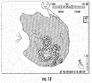
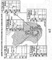
- Figures 1A , 1B and 2 each show post-ischemic VT characterized by endo-epicardial low or intermediate voltage area in which signal conduction is slowed down. This illustrates that measuring any prolonged potential inside or around the dense scar area may help identify potential isthmuses sustaining VT.
- Figures 1A , 1B and 2 also illustrate substrate mapping acquiring bipolar and potential duration information by ablation or multi-electrode (MEM) catheter.
- Figure 1A illustrates the bipolar signal amplitude (Bi) variance in the various sectors of the heart;
- Figure 1A shows Bi ranges from 0.5 mV to 1.5mV.
- Figure 1B illustrates the Shortex Complex Interval (SCI) variance in the various sectors of the heart; SCI ranges from 15.0msec to 171.00msec with the SCI range of interest between 80msec and 170msec.
- Figure 2 shows the EGM graphs associated with five distinct portions of the heart; these five portions are located within the critical area having Bi between 0.5 mV and 1.0 mV and SCI between 80msec and 170msec.
- the EGMs shown in Figure 2 can be identified by MAP 1-2 or MAP 3-4.
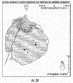
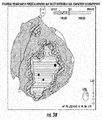
- Figure 3A shows an epicardial voltage map and Figure 3B shows PDM.
- the three black circles in Figures 3A and 3B are marked as abnormally prolonged potentials, e.g., potentials above 200msec.
- Figure 4 shows epicardial PDM of left ventricle non-compaction cardiomyopathy.
- typical ventricular fragmented and prolonged potentials are shown with an initial component characterized by normal (>1.5 mV) amplitude.
- the EGMs of interest e.g., those having abnormally prolonged potentials (shown as black circles), can be identified by MAP 1-2 or MAP 3-4 in Figure 4 .
- Figure 6 shows typical fragmented and prolonged mesodiastolic potentials identified during atrial tachycardia; note that one may set the color bar threshold according to the case.
- the EGMs shown in Figure 6 can be identified by MAP 1-2 or MAP 3-4.
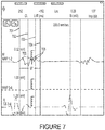
- Figure 7 is an EGM which shows a mesodiastolic potential.
- LAT WOI cannot be modified depending on fragmentation of potentials during tachycardia, setting two different WOI can be useful.
- Figure 7 shows vertical lines 701, 702, 703, 704 that border example WOIs. Accordingly, one WOI can exist between lines 701 and 702 and a second WOI can exist between lines 703 and 704.
- peaks 705 of the EGM are annotated.
- the potential can be measured using the CARTO®3 CFAE module by manually annotating the duration outside the LAT WOI. In the present system, automated annotation can be performed.
- FIG. 8 is a flow diagram of an example method in an embodiment of the invention.
- the EGM of Figure 7 may be used to illustrate the embodiment shown in Figure 8 .
- the example method is performed as follows:
- step S801 define Window Of Interest (WOI) which is the interval in the EGM and/or ECG which is normally used to calculate the voltage amplitude, [peak to peak mV] and the signal duration.
- WOI Window Of Interest
- the WOI can be set according to the arrhythmia.
- the WOI for atrial flutter can be from -70ms to 230ms if the cycle length is 250ms.
- LAT WOI and PDM WOI as discussed above.
- step S802 calculate at least two previous heart beats based on cycle length and reference annotation, and assign WOI for both heart beats.
- each electroanatomical acquired point e.g., point EGM
- Map Type such as PDM, LAT, Bipolar Voltage etc.
- a window equal to 2500ms of ECG and EGM is recorded.
- the reference annotation for a heartbeat lays at 2000ms
- the first WOI [-50ms, 350ms] goes from 2000ms - 50ms (e.g., 1950ms) to 2000ms + 350ms (e.g., 2350ms).
- the heart beat cycle length is 800ms, there is more than one heart beat in the 2500ms.
- the previous heart beat reference lays at 1200ms (2000ms - 800ms [e.g., 1200ms]) and the WOI will be from 1200ms -50ms (e.g., 1150ms) to 1200ms + 350ms (e.g., 1550ms).
- the abovementioned time intervals have been used by way of example and should not be considered as limiting.
- step S803 for each WOI of each heartbeat, the Potential Duration is calculated as shown in steps S804-S814, as follows.
- step S804 calculate the heartbeat peaks based on a predetermined threshold in WOI and create a list of peaks in WOI.
- the threshold for defining the peaks is +/-0.05mV.
- the EGM signal values are measured in mV, and, in one example, a peak with mV value greater than 0.05mV is marked.
- the peak threshold may be set by the physician. Typically the threshold is in accordance with the arrhythmia.
- step S805 Potential Duration Start is defined by checking from the beginning of WOI, as shown in steps S806-S808 as follows.
- step S806 determine whether two consecutive peaks have the same sign and the absolute value of both are less than 2*Min.
- step S809 Potential Duration End is defined, checking from the ending of WOI, as shown in steps S810-S814 as follows.
- step S810 determine whether two consecutive peaks distance is greater than 120ms.
- step S812 determine whether two consecutive peaks have the same sign and both peaks absolute values are less than 2*Min Threshold or whether the time between two consecutive peaks is less than 25ms.
- another filter may be taken into account for the automatic software. Stability and reproducibility of the duration of the potential can be crucial.
- the system can verify, in presence of a double or late potential, that the late activity is also present in all the beats included in the 2500ms recording window.
- step S815 calculate Potential Duration Value as the difference between Potential Duration Start and Potential Duration End in ms.
- step S816 set the selected point potential duration value as the heart beat which has the minimum standard deviation of the positions on each heart beat WOI.
- any EGM showing a duration ⁇ 200ms is considered abnormal, and thus represents the target for catheter ablation.
- Three different concentric areas are identified according to the degree of prolongation by setting different cut-off intervals.
- Atypical Atrial Flutter a duration of ⁇ 70ms can be marked as target for ablation.
- Ischemic VT a duration of ⁇ 170ms can targeted for ablation.
- cardiomyopathies a duration of ⁇ 200ms can be marked for ablation.
- the different cut-offs depend upon each patient condition and the type of arrhythmia treated. They can be used to guide the ablation procedure, but they are not to be considered as limiting.
- Figure 9 is an illustration of an example medical system 900 that may be used to generate and display information 52 (e.g., PDM and other maps and anatomical models of a portion of a patient and signal information).
- Tools such as tool 22, can be any tool used for diagnostic or therapeutic treatment, such as for example, a catheter having a plurality of electrodes for mapping electrical potentials in a heart 26 of a patient 28.
- tools may be used, mutatis mutandis, for other therapeutic and/or diagnostic purposes of different portions of anatomy, such as in the heart, lungs or other body organs, such as the ear, nose, and throat (ENT).
- Tools may include, for example, probes, catheters, cutting tools and suction devices.
- An operator 30 may insert the tool 22 into a portion of patient anatomy, such as the vascular system of the patient 28 so that a tip 56 of the tool 22 enters a chamber of the heart 26.
- the control console 24 may use magnetic position sensing to determine 3-D position coordinates of the tool (e.g., coordinates of the tip 56) inside the heart 26.
- a driver circuit 34 in the control console 24 may drive, via connector, 44, field generators 36 to generate magnetic fields within the anatomy of the patient 28.
- the field generators 36 include one or more emitter coils (not shown in Figure 9 ), placed at known positions external to the patient 28, which are configured to generate magnetic fields in a predefined working volume that contains a portion of interest of the patient anatomy. Each of the emitting coils may be driven by a different frequency to emit a constant magnetic field. For example, in the example medical system 900 shown in Figure 9 , one or more emitter coils can be placed below the torso of the patient 28 and each configured to generate magnetic fields in a predefined working volume that contains the heart 26 of the patient.
- a magnetic field location sensor 38 is disposed at the tip 56 of tool 22.
- the magnetic field location sensor 38 generates electrical signals, based on the amplitude and phase of the magnetic fields, indicating the 3-D position coordinates of the tool (e.g., position coordinates of the tip 56).
- the electrical signals may be communicated to the control console 24 to determine the position coordinates of the tool.
- the electrical signals may be communicated to the control console 24 via wire 45.
- the electrical signals may be wirelessly communicated to the control console 24, for example, via a wireless communication interface (not shown) at the tool 22 that may communicate with input/output (I/O) interface 42 in the control console 24.
- a wireless communication interface not shown
- I/O input/output
- U.S. Pat. No. 6,266,551 whose disclosure is incorporated herein by reference, describes, inter alia, a wireless catheter, which is not physically connected to signal processing and/or computing apparatus and is incorporated herein by reference. Rather, a transmitter/receiver is attached to the proximal end of the catheter. The transmitter/receiver communicates with a signal processing and/or computer apparatus using wireless communication methods, such as IR, RF, Bluetooth, or acoustic transmissions.
- the wireless digital interface and the I/O interface 42 may operate in accordance with any suitable wireless communication standard that is known in the art, such as for example, IR, RF, Bluetooth, one of the IEEE 802.11 family of standards (e.g., Wi-Fi), or the HiperLAN standard.
- any suitable wireless communication standard such as for example, IR, RF, Bluetooth, one of the IEEE 802.11 family of standards (e.g., Wi-Fi), or the HiperLAN standard.
- Figure 9 shows a single magnetic field location sensor 38 disposed at the tip 56 of tool 22, tools may include one or more magnetic field location sensors each disposed at any tool portion.
- the magnetic field location sensor 38 may include one or more miniature coils (not shown).
- a magnetic field location sensor may include multiple miniature coils oriented along different axes.
- the magnetic field location sensor may comprise either another type of magnetic sensor or position transducers of other types, such as impedance-based or ultrasonic location sensors.
- the signal processor 40 is configured to process the signals to determine the position coordinates of the tool 22, including both location and orientation coordinates.
- the method of position sensing described hereinabove is implemented in the CARTOTM mapping system produced by Biosense Webster Inc., of Diamond Bar, Calif., and is described in detail in the patents and the patent applications cited herein.
- the tool 22 may also include a force sensor 54 contained within the tip 56.
- the force sensor 54 may measure a force applied by the tool 22 (e.g., the tip 56 of the tool) to the endocardial tissue of the heart 26 and generate a signal that is sent to the control console 24.
- the force sensor 54 may include a magnetic field transmitter and a receiver connected by a spring in the tip 56, and may generate an indication of the force based on measuring a deflection of the spring. Further details of this sort of probe and force sensor are described in U.S. Patent Application Publications 2009/0093806 and 2009/0138007 , whose disclosures are incorporated herein by reference.
- the tip 56 may include another type of force sensor that may use, for example, fiber optics or impedance measurements.
- the tool 22 may also include an electrode 48 coupled to the tip 56 and configured to function as an impedance-based position transducer. Additionally or alternatively, the electrode 48 may be configured to measure a certain physiological property, for example the local surface electrical potential (e.g., of cardiac tissue) at one or more locations. The electrode 48 may be configured to apply RF energy to ablate endocardial tissue in the heart 26.
- an electrode 48 coupled to the tip 56 and configured to function as an impedance-based position transducer. Additionally or alternatively, the electrode 48 may be configured to measure a certain physiological property, for example the local surface electrical potential (e.g., of cardiac tissue) at one or more locations. The electrode 48 may be configured to apply RF energy to ablate endocardial tissue in the heart 26.
- a certain physiological property for example the local surface electrical potential (e.g., of cardiac tissue) at one or more locations.
- the electrode 48 may be configured to apply RF energy to ablate endocardial tissue in the heart 26.
- the example medical system 900 may be configured to measure the position of the tool 22 using magnetic-based sensors
- other position tracking techniques may be used (e.g., impedance-based sensors).
- Magnetic position tracking techniques are described, for example, in U.S. Pat. Nos. 5,391,199 , 5,443,489 , 6,788,967 , 6,690,963 , 5,558,091 , 6,172,499 6,177,792 , the disclosures of which are incorporated herein by reference.
- Impedance-based position tracking techniques are described, for example, in U.S. Pat. Nos. 5,983,126 , 6,456,828 and 5,944,022 , the disclosures of which are incorporated herein by reference.
- the I/O interface 42 may enable the control console 24 to interact with the tool 22, the body surface electrodes 46 and any other sensors (not shown). Based on the electrical impulses received from the body surface electrodes 46 and the electrical signals received from the tool 22 via the I/O interface 42 and other components of medical system 900, the signal processor 40 may determine the location of the tool in a 3-D space and generate the display information 52, which may be shown on a display 50.
- the signal processor 40 may be included in a general-purpose computer, with a suitable front end and interface circuits for receiving signals from the tool 22 and controlling the other components of the control console 24.
- the signal processor 40 may be programmed, using software, to perform the functions that are described herein.
- the software may be downloaded to the control console 24 in electronic form, over a network, for example, or it may be provided on non-transitory tangible media, such as optical, magnetic or electronic memory media.
- some or all of the functions of the signal processor 40 may be performed by dedicated or programmable digital hardware components.
- the control console 24 is connected, via cable 44, to body surface electrodes 46, each of which are attached to patient 28 using patches (e.g., indicated in Figure 9 as circles around the electrodes 46) that adhere to the skin of the patient.
- Body surface electrodes 46 may include one or more wireless sensor nodes integrated on a flexible substrate.
- the one or more wireless sensor nodes may include a wireless transmit/receive unit (WTRU) enabling local digital signal processing, a radio link, and a miniaturized rechargeable battery.
- WTRU wireless transmit/receive unit
- body surface electrodes 46 may also be positioned on the patient using articles worn by patient 28 which include the body surface electrodes 46 and may also include one or more position sensors (not shown) indicating the location of the worn article.
- body surface electrodes 46 can be embedded in a vest that is configured to be worn by the patient 28. During operation, the body surface electrodes 46 assist in providing a location of the tool (e.g., catheter) in 3-D space by detecting electrical impulses generated by the polarization and depolarization of cardiac tissue and transmitting information to the control console 24, via the cable 44.
- the body surface electrodes 46 can be equipped with magnetic location tracking and can help identify and track the respiration cycle of the patient 28.
- the body surface electrodes 46 may communicate with the control console 24 and one another via a wireless interface (not shown).
- the signal processor 40 may present the display information 52 and may store data representing the information 52 in a memory 58.
- the memory 58 may include any suitable volatile and/or non-volatile memory, such as random access memory or a hard disk drive.
- the operator 30 may be able to manipulate the display information 52 using one or more input devices 59.
- the medical system 900 may include a second operator that manipulates the control console 24 while the operator 30 manipulates the tool 22. It should be noted that the configuration shown in Figure 9 is exemplary. Any suitable configuration of the medical system 900 may be used and implemented.
- FIG 10 is a block diagram illustrating example components of a medical system 1000 in which features described herein can be implemented.
- the system 1000 includes catheter 1002, processing device 1004, display device 1006 and memory 1012.
- the processing device 1004, display device 1006 and memory 1012 are a part of computing device 1014.
- the display device 1006 may be separate from computing device 1014.
- Computing device 1014 may also include an I/O interface, such as I/O interface 42 shown in Figure 9 .
- Catheter 1002 includes a plurality of catheter electrodes 1008 for detecting the electrical activity of the heart over time.
- Catheter 1002 also includes sensor(s) 1016, which include, for example, sensors (e.g., a magnetic field location sensor) for providing location signals to indicate the location of the catheter 1002 in a 3-D space as well as sensors (e.g., position sensors, pressure or force sensors, temperature sensors, impedance sensors) for providing ablation parameter signals during the ablation of the heart tissue.
- the example system 1000 also includes one or more additional sensors 1010, separate from the catheter 1002, used to provide location signals indicating the location of the catheter 1002 in a 3D space.
- the system 1002 shown in example system 1000 also includes an RF generator 1018, which supplies high-frequency electrical energy, via catheter 1002, for ablating tissue at locations engaged by the catheter 1002. Accordingly, catheter 1002 may be used to acquire electrical activity for generating mapping of the heart as well ablating cardiac tissue. As described above, however, embodiments may include catheters used to acquire the electrical activity for generating mapping of the heart while not used to ablate cardiac tissue.
- Processing device 1004 may include one or more processors each configured to process the ECG signals, record ECG signals over time, filter ECG signals, fractionate ECG signals into signal components (e.g., slopes, waves, complexes) and generate and combine ECG signal information for displaying the plurality of electrical signals on display device 1006. Processing device 1004 may also generate and interpolate mapping information for displaying maps of the heart on display device 1006. Processing device 1004 may include one or more processors (e.g., signal processor 40) configured to process the location information acquired from sensors (e.g., additional sensor(s) 1010 and catheter sensor(s) 1016) to determine location and orientation coordinates.
- sensors e.g., additional sensor(s) 1010 and catheter sensor(s) 1016) to determine location and orientation coordinates.
- Processing device 1004 is also configured to drive display device 1006 to display dynamic maps (i.e., spatio-temporal maps) of the heart and the electrical activity of the heart using the mapping information and the ECG data.
- Display device 1006 may include one or more displays each configured to display maps of the heart representing spatio-temporal manifestations of the electrical activity of the heart over time and display the ECG signals acquired from the heart over time.
- the catheter electrodes 1008, catheter sensor(s) 1016 and additional sensor(s) 1010 may be in wired or wireless communication with processing device 1004.
- Display device 1006 may also be in wired or wireless communication with processing device 1004.
- FIG 11 is a work flow diagram showing a mapping procedure in cardiomyopathies.
- the procedure begins. This may include inserting a tool 22, such as a catheter, into a patient, and administering a drug, such as ajmaline that may be used to bring out typical findings of ST elevations in patients suspected of having Brugada syndrome.
- a tool 22 such as a catheter
- a drug such as ajmaline
- step S1102 endocardial bipolar-duration RV/LV mapping is performed.
- a signal processor e.g., computer 40, using the CFAE module of CARTO3 may be used.
- a 3D epicardial duration map is produced. In one embodiment, this map is displayed on display 50.
- the epicardial duration map may comprise one or more of a voltage map, an LAT and a PDM.
- abnormal long-duration bipolar electrograms may be defined as low-frequency (up to 100HZ) prolonged duration (>200ms) bipolar signals with delayed activity extending beyond the end of the QRS complex.
- step S1105 catheter ablation of delimited areas is performed, and in step S1106, an epicardial duration remap is created.
- catheter ablation may be performed during sinus rhythm using a stepwise strategy in a descending order of abnormal potential duration as displayed on the map and beginning from the longest potentials.
- ablation is performed using radiofrequency (RF), which may be applied by a dragging technique that does not significantly affect either voltage amplitude or local activation times, thus immediately "homogenizing" the entire abnormal area.
- RF radiofrequency
- processors include, by way of example, a general purpose processor, a special purpose processor, a conventional processor, a digital signal processor (DSP), a plurality of microprocessors, one or more microprocessors in association with a DSP core, a controller, a microcontroller, Application Specific Integrated Circuits (ASICs), Field Programmable Gate Arrays (FPGAs) circuits, any other type of integrated circuit (IC), and/or a state machine.
- DSP digital signal processor
- ASICs Application Specific Integrated Circuits
- FPGAs Field Programmable Gate Arrays
- Such processors can be manufactured by configuring a manufacturing process using the results of processed hardware description language (HDL) instructions and other intermediary data including netlists (such instructions capable of being stored on a computer readable media). The results of such processing can be maskworks that are then used in a semiconductor manufacturing process to manufacture a processor which implements features of the disclosure.
- HDL hardware description language
- non-transitory computer-readable storage mediums include a read only memory (ROM), a random access memory (RAM), a register, cache memory, semiconductor memory devices, magnetic media such as internal hard disks and removable disks, magneto-optical media, and optical media such as CD-ROM disks, and digital versatile disks (DVDs).
- ROM read only memory
- RAM random access memory
- register cache memory
- semiconductor memory devices magnetic media such as internal hard disks and removable disks, magneto-optical media, and optical media such as CD-ROM disks, and digital versatile disks (DVDs).
Landscapes
- Health & Medical Sciences (AREA)
- Life Sciences & Earth Sciences (AREA)
- Surgery (AREA)
- Engineering & Computer Science (AREA)
- Cardiology (AREA)
- Heart & Thoracic Surgery (AREA)
- Public Health (AREA)
- Biomedical Technology (AREA)
- General Health & Medical Sciences (AREA)
- Medical Informatics (AREA)
- Molecular Biology (AREA)
- Veterinary Medicine (AREA)
- Animal Behavior & Ethology (AREA)
- Physics & Mathematics (AREA)
- Pathology (AREA)
- Biophysics (AREA)
- Nuclear Medicine, Radiotherapy & Molecular Imaging (AREA)
- Physiology (AREA)
- Radiology & Medical Imaging (AREA)
- Robotics (AREA)
- Plasma & Fusion (AREA)
- Otolaryngology (AREA)
- Measurement And Recording Of Electrical Phenomena And Electrical Characteristics Of The Living Body (AREA)
- Surgical Instruments (AREA)
Applications Claiming Priority (2)
| Application Number | Priority Date | Filing Date | Title |
|---|---|---|---|
| US201762450381P | 2017-01-25 | 2017-01-25 | |
| US15/854,492 US10952793B2 (en) | 2017-01-25 | 2017-12-26 | Method and system for eliminating a broad range of cardiac conditions by analyzing intracardiac signals providing a detailed map and determining potential ablation points |
Publications (3)
| Publication Number | Publication Date |
|---|---|
| EP3354192A1 true EP3354192A1 (de) | 2018-08-01 |
| EP3354192C0 EP3354192C0 (de) | 2024-01-03 |
| EP3354192B1 EP3354192B1 (de) | 2024-01-03 |
Family
ID=61094224
Family Applications (1)
| Application Number | Title | Priority Date | Filing Date |
|---|---|---|---|
| EP18153252.4A Active EP3354192B1 (de) | 2017-01-25 | 2018-01-24 | System und computerprogrammprodukt zur verbesserung von ablationsverfahren |
Country Status (7)
| Country | Link |
|---|---|
| US (1) | US10952793B2 (de) |
| EP (1) | EP3354192B1 (de) |
| JP (1) | JP7109925B2 (de) |
| CN (1) | CN108338786A (de) |
| AU (1) | AU2018200519A1 (de) |
| CA (1) | CA2992869A1 (de) |
| IL (1) | IL256950B (de) |
Cited By (4)
| Publication number | Priority date | Publication date | Assignee | Title |
|---|---|---|---|---|
| WO2021173206A1 (en) * | 2020-02-27 | 2021-09-02 | St. Jude Medical, Cardiology Division, Inc. | Systems and methods for mapping local activation times |
| US12310737B2 (en) | 2020-09-30 | 2025-05-27 | Boston Scientific Scimed, Inc. | Interactive 2D scatter plot of EGM characteristic metrics |
| US12471828B2 (en) | 2020-09-30 | 2025-11-18 | Boston Scientific Scimed, Inc. | Electrophysiology system and method for determining local cycle length and local duty cycle |
| EP4670661A1 (de) * | 2024-06-29 | 2025-12-31 | Substrate HD | Computerimplementiertes herzchirurgieunterstützungsverfahren |
Families Citing this family (19)
| Publication number | Priority date | Publication date | Assignee | Title |
|---|---|---|---|---|
| US11389232B2 (en) | 2006-06-28 | 2022-07-19 | Kardium Inc. | Apparatus and method for intra-cardiac mapping and ablation |
| US9119633B2 (en) | 2006-06-28 | 2015-09-01 | Kardium Inc. | Apparatus and method for intra-cardiac mapping and ablation |
| US8906011B2 (en) | 2007-11-16 | 2014-12-09 | Kardium Inc. | Medical device for use in bodily lumens, for example an atrium |
| US10827977B2 (en) | 2012-05-21 | 2020-11-10 | Kardium Inc. | Systems and methods for activating transducers |
| US9017321B2 (en) | 2012-05-21 | 2015-04-28 | Kardium, Inc. | Systems and methods for activating transducers |
| US9198592B2 (en) | 2012-05-21 | 2015-12-01 | Kardium Inc. | Systems and methods for activating transducers |
| US11571160B2 (en) | 2013-01-16 | 2023-02-07 | University Of Vermont | Methods and systems for wavelength mapping cardiac fibrillation and optimizing ablation lesion placement |
| US10722184B2 (en) | 2014-11-17 | 2020-07-28 | Kardium Inc. | Systems and methods for selecting, activating, or selecting and activating transducers |
| US10368936B2 (en) | 2014-11-17 | 2019-08-06 | Kardium Inc. | Systems and methods for selecting, activating, or selecting and activating transducers |
| EP3886694B1 (de) * | 2018-11-30 | 2025-11-12 | University of Vermont | Systeme zur wellenlängenkartierung von herzflimmern und zur optimierung der platzierung von ablationsläsionen |
| US10905349B1 (en) * | 2019-07-16 | 2021-02-02 | Biosense Webster (Israel) Ltd. | Mapping atrial fibrillation using fragmentation index |
| US11844616B2 (en) * | 2019-08-13 | 2023-12-19 | Biosense Webster (Israel) Ltd. | Enhanced visualization of organ electrical activity |
| US20210169359A1 (en) * | 2019-12-06 | 2021-06-10 | Biosense Webster (Israel) Ltd. | Intra-cardiac pattern matching |
| US11537852B2 (en) * | 2020-02-13 | 2022-12-27 | International Business Machines Corporation | Evolving graph convolutional networks for dynamic graphs |
| US11160485B2 (en) * | 2020-04-01 | 2021-11-02 | Biosense Webster (Israel) Ltd. | Propagation map of a heart chamber with areas demonstrating fractionated electrograms |
| JP7758264B2 (ja) * | 2020-06-19 | 2025-10-22 | バイオセンス・ウエブスター・(イスラエル)・リミテッド | オートエンコーダを使用した心室遠距離場推定 |
| US20220008126A1 (en) * | 2020-07-07 | 2022-01-13 | Biosense Webster (Israel) Ltd. | Optimized ablation for persistent atrial fibrillation |
| US20220079491A1 (en) * | 2020-09-14 | 2022-03-17 | Biosense Webster (Israel) Ltd. | Local activation time analysis system |
| US11589795B2 (en) * | 2020-12-22 | 2023-02-28 | Biosense Webster (Israel) Ltd. | Annotation of late potentials comprising local abnormal ventricular activation (LAVA) signals |
Citations (14)
| Publication number | Priority date | Publication date | Assignee | Title |
|---|---|---|---|---|
| US5391199A (en) | 1993-07-20 | 1995-02-21 | Biosense, Inc. | Apparatus and method for treating cardiac arrhythmias |
| US5558091A (en) | 1993-10-06 | 1996-09-24 | Biosense, Inc. | Magnetic determination of position and orientation |
| US5944022A (en) | 1997-04-28 | 1999-08-31 | American Cardiac Ablation Co. Inc. | Catheter positioning system |
| US5983126A (en) | 1995-11-22 | 1999-11-09 | Medtronic, Inc. | Catheter location system and method |
| US6172499B1 (en) | 1999-10-29 | 2001-01-09 | Ascension Technology Corporation | Eddy current error-reduced AC magnetic position measurement system |
| US6177792B1 (en) | 1996-03-26 | 2001-01-23 | Bisense, Inc. | Mutual induction correction for radiator coils of an objects tracking system |
| US6266551B1 (en) | 1996-02-15 | 2001-07-24 | Biosense, Inc. | Catheter calibration and usage monitoring system |
| US6456828B1 (en) | 1997-02-12 | 2002-09-24 | Interdigital Technology Corporation | Base station using global channel power control |
| WO2003011112A2 (en) * | 2001-07-30 | 2003-02-13 | The Trustees Of Columbia University In The City Of New York | System and method for determining reentrant ventricular tachycardia isthmus location and shape for catheter ablation |
| US6690963B2 (en) | 1995-01-24 | 2004-02-10 | Biosense, Inc. | System for determining the location and orientation of an invasive medical instrument |
| WO2006066324A1 (en) * | 2004-12-21 | 2006-06-29 | Sydney West Area Health Service | Automated processing of electrophysiological data |
| US20090093806A1 (en) | 2007-10-08 | 2009-04-09 | Assaf Govari | Catheter with pressure sensing |
| US20090138007A1 (en) | 2007-10-08 | 2009-05-28 | Assaf Govari | High-sensitivity pressure-sensing probe |
| EP2901953A1 (de) * | 2014-01-29 | 2015-08-05 | Biosense Webster (Israel), Ltd. | Doppelt bipolare Konfiguration für Vorhofflimmernannotation |
Family Cites Families (18)
| Publication number | Priority date | Publication date | Assignee | Title |
|---|---|---|---|---|
| DE69315354T2 (de) | 1992-09-23 | 1998-03-19 | Endocardial Solutions Inc | Endokard-mapping system |
| DE19801240A1 (de) | 1998-01-12 | 1999-07-29 | Cybernetic Vision Ag | Verfahren und Vorrichtung zur Darstellung und Überwachung von Funktionsparametern eines physiologischen Systems |
| US6633773B1 (en) * | 2000-09-29 | 2003-10-14 | Biosene, Inc. | Area of interest reconstruction for surface of an organ using location data |
| US7123954B2 (en) | 2002-09-19 | 2006-10-17 | Sanjiv Mathur Narayan | Method for classifying and localizing heart arrhythmias |
| US7794454B2 (en) | 2003-07-11 | 2010-09-14 | Medtronic Cryocath Lp | Method and device for epicardial ablation |
| US7477936B2 (en) | 2003-12-19 | 2009-01-13 | Aalborg Universitet | System and a method for analyzing ECG curvature |
| EP1922005B1 (de) * | 2005-08-25 | 2011-12-21 | Koninklijke Philips Electronics N.V. | System zur elektrophysiologischen wiedergewinnung einer stütze zur fortführung von linien- und ring-ableitungen |
| US7774051B2 (en) * | 2006-05-17 | 2010-08-10 | St. Jude Medical, Atrial Fibrillation Division, Inc. | System and method for mapping electrophysiology information onto complex geometry |
| US8010186B1 (en) * | 2006-07-19 | 2011-08-30 | Pacesetter, Inc. | System and related methods for identifying a fibrillation driver |
| US8116859B2 (en) | 2007-10-24 | 2012-02-14 | Ela Medical S.A.S. | Electrocardiologic device for the assisted diagnosis of brugada syndrome or early repolarization syndrome |
| US9277956B2 (en) | 2011-11-09 | 2016-03-08 | Siemens Medical Solutions Usa, Inc. | System for automatic medical ablation control |
| WO2013123549A1 (en) | 2012-02-20 | 2013-08-29 | Adelaide Research & Innovation Pty Ltd | Method for identifying a cardiac region for ablation |
| EP2676604B1 (de) | 2012-06-19 | 2016-08-10 | Texas Instruments France | Echtzeit-QRS-Dauermessung in einem Elektrokardiogramm |
| US20140081262A1 (en) | 2012-09-20 | 2014-03-20 | Boston Scientific Scimed Inc. | Nearfield ultrasound echography mapping |
| CN105324067B (zh) * | 2013-05-06 | 2017-10-24 | 波士顿科学医学有限公司 | 实时或回放电生理数据可视化期间的最近的跳动特性的持续显示 |
| US9259165B2 (en) | 2014-02-26 | 2016-02-16 | Biosense Webster (Israel) Ltd. | Determination of reference annotation time from multi-channel electro-cardiogram signals |
| US10980439B2 (en) * | 2014-08-06 | 2021-04-20 | Biosense Webster (Israel) Ltd | Wavefront analysis based on ablation parameters |
| JP6514334B2 (ja) | 2015-01-28 | 2019-05-15 | セント・ジュード・メディカル,カーディオロジー・ディヴィジョン,インコーポレイテッド | 熱マッピング・カテーテル |
-
2017
- 2017-12-26 US US15/854,492 patent/US10952793B2/en active Active
-
2018
- 2018-01-16 IL IL256950A patent/IL256950B/en unknown
- 2018-01-23 AU AU2018200519A patent/AU2018200519A1/en not_active Abandoned
- 2018-01-24 EP EP18153252.4A patent/EP3354192B1/de active Active
- 2018-01-24 JP JP2018009433A patent/JP7109925B2/ja active Active
- 2018-01-24 CA CA2992869A patent/CA2992869A1/en not_active Abandoned
- 2018-01-25 CN CN201810075404.5A patent/CN108338786A/zh active Pending
Patent Citations (16)
| Publication number | Priority date | Publication date | Assignee | Title |
|---|---|---|---|---|
| US5443489A (en) | 1993-07-20 | 1995-08-22 | Biosense, Inc. | Apparatus and method for ablation |
| US5391199A (en) | 1993-07-20 | 1995-02-21 | Biosense, Inc. | Apparatus and method for treating cardiac arrhythmias |
| US5558091A (en) | 1993-10-06 | 1996-09-24 | Biosense, Inc. | Magnetic determination of position and orientation |
| US6690963B2 (en) | 1995-01-24 | 2004-02-10 | Biosense, Inc. | System for determining the location and orientation of an invasive medical instrument |
| US5983126A (en) | 1995-11-22 | 1999-11-09 | Medtronic, Inc. | Catheter location system and method |
| US6266551B1 (en) | 1996-02-15 | 2001-07-24 | Biosense, Inc. | Catheter calibration and usage monitoring system |
| US6177792B1 (en) | 1996-03-26 | 2001-01-23 | Bisense, Inc. | Mutual induction correction for radiator coils of an objects tracking system |
| US6456828B1 (en) | 1997-02-12 | 2002-09-24 | Interdigital Technology Corporation | Base station using global channel power control |
| US5944022A (en) | 1997-04-28 | 1999-08-31 | American Cardiac Ablation Co. Inc. | Catheter positioning system |
| US6788967B2 (en) | 1997-05-14 | 2004-09-07 | Biosense, Inc. | Medical diagnosis, treatment and imaging systems |
| US6172499B1 (en) | 1999-10-29 | 2001-01-09 | Ascension Technology Corporation | Eddy current error-reduced AC magnetic position measurement system |
| WO2003011112A2 (en) * | 2001-07-30 | 2003-02-13 | The Trustees Of Columbia University In The City Of New York | System and method for determining reentrant ventricular tachycardia isthmus location and shape for catheter ablation |
| WO2006066324A1 (en) * | 2004-12-21 | 2006-06-29 | Sydney West Area Health Service | Automated processing of electrophysiological data |
| US20090093806A1 (en) | 2007-10-08 | 2009-04-09 | Assaf Govari | Catheter with pressure sensing |
| US20090138007A1 (en) | 2007-10-08 | 2009-05-28 | Assaf Govari | High-sensitivity pressure-sensing probe |
| EP2901953A1 (de) * | 2014-01-29 | 2015-08-05 | Biosense Webster (Israel), Ltd. | Doppelt bipolare Konfiguration für Vorhofflimmernannotation |
Non-Patent Citations (1)
| Title |
|---|
| F. DEL CARPIO MUNOZ ET AL: "Teaching Points With 3-Dimensional Mapping of Cardiac Arrhythmias: Taking Points: Activation Mapping", CIRCULATION. ARRHYTHMIA AND ELECTROPHYSIOLOGY, vol. 4, no. 3, 1 June 2011 (2011-06-01), United States, pages e22 - e25, XP055350906, ISSN: 1941-3149, DOI: 10.1161/CIRCEP.110.960351 * |
Cited By (5)
| Publication number | Priority date | Publication date | Assignee | Title |
|---|---|---|---|---|
| WO2021173206A1 (en) * | 2020-02-27 | 2021-09-02 | St. Jude Medical, Cardiology Division, Inc. | Systems and methods for mapping local activation times |
| US12310737B2 (en) | 2020-09-30 | 2025-05-27 | Boston Scientific Scimed, Inc. | Interactive 2D scatter plot of EGM characteristic metrics |
| US12471828B2 (en) | 2020-09-30 | 2025-11-18 | Boston Scientific Scimed, Inc. | Electrophysiology system and method for determining local cycle length and local duty cycle |
| EP4670661A1 (de) * | 2024-06-29 | 2025-12-31 | Substrate HD | Computerimplementiertes herzchirurgieunterstützungsverfahren |
| WO2026003299A1 (en) * | 2024-06-29 | 2026-01-02 | Substrate Hd | Computer implemented heart surgery assistance method |
Also Published As
| Publication number | Publication date |
|---|---|
| JP7109925B2 (ja) | 2022-08-01 |
| US10952793B2 (en) | 2021-03-23 |
| EP3354192C0 (de) | 2024-01-03 |
| CA2992869A1 (en) | 2018-07-25 |
| JP2018149271A (ja) | 2018-09-27 |
| US20180206920A1 (en) | 2018-07-26 |
| IL256950B (en) | 2022-02-01 |
| IL256950A (en) | 2018-02-28 |
| EP3354192B1 (de) | 2024-01-03 |
| CN108338786A (zh) | 2018-07-31 |
| AU2018200519A1 (en) | 2018-08-09 |
Similar Documents
| Publication | Publication Date | Title |
|---|---|---|
| EP3354192B1 (de) | System und computerprogrammprodukt zur verbesserung von ablationsverfahren | |
| JP7622162B2 (ja) | 最早期のlatの自動表示 | |
| JP7473643B2 (ja) | アブレーション機器の追跡及び損傷線の生成のための方法、システム、及び装置 | |
| EP3482679A1 (de) | System und verfahren zur bereitstellung von auditiver führung in medizinischen systemen | |
| US11819281B2 (en) | Analyzing and mapping ECG signals and determining ablation points to eliminate Brugada syndrome | |
| US11844614B2 (en) | Analyzing and mapping ECG signals and determining ablation points to eliminate Brugada syndrome | |
| EP3320944A1 (de) | Multielektrodenkatheter zur verhinderung einer physiologischen fluidstromeinschränkung | |
| CA2992909A1 (en) | Analyzing and mapping ecg signals and determining ablation points to eliminate brugada syndrome | |
| EP3444822B1 (de) | System und verfahren zur verwaltung von ekg-daten für benutzerdefinierte karte | |
| US12458438B2 (en) | Cardiac vein ablation visualization system and catheter | |
| US11701050B2 (en) | Data reuse for filling in missing data points | |
| CN120436653A (zh) | 本地ecg注释可视化 | |
| AU2019200267A1 (en) | Analyzing and mapping ECG signals and determining ablation points to elimate Brugada syndrome |
Legal Events
| Date | Code | Title | Description |
|---|---|---|---|
| PUAI | Public reference made under article 153(3) epc to a published international application that has entered the european phase |
Free format text: ORIGINAL CODE: 0009012 |
|
| STAA | Information on the status of an ep patent application or granted ep patent |
Free format text: STATUS: THE APPLICATION HAS BEEN PUBLISHED |
|
| AK | Designated contracting states |
Kind code of ref document: A1 Designated state(s): AL AT BE BG CH CY CZ DE DK EE ES FI FR GB GR HR HU IE IS IT LI LT LU LV MC MK MT NL NO PL PT RO RS SE SI SK SM TR |
|
| AX | Request for extension of the european patent |
Extension state: BA ME |
|
| APBK | Appeal reference recorded |
Free format text: ORIGINAL CODE: EPIDOSNREFNE |
|
| APBN | Date of receipt of notice of appeal recorded |
Free format text: ORIGINAL CODE: EPIDOSNNOA2E |
|
| APBR | Date of receipt of statement of grounds of appeal recorded |
Free format text: ORIGINAL CODE: EPIDOSNNOA3E |
|
| APBV | Interlocutory revision of appeal recorded |
Free format text: ORIGINAL CODE: EPIDOSNIRAPE |
|
| RIN1 | Information on inventor provided before grant (corrected) |
Inventor name: TURGEMAN, AHARON Inventor name: PAPPONE, CARLO Inventor name: POZZI, PAOLI Inventor name: NATALIZIA, ANDREA |
|
| RAP1 | Party data changed (applicant data changed or rights of an application transferred) |
Owner name: PAPPONE, CARLO Owner name: BIOSENSE WEBSTER (ISRAEL) LTD. |
|
| STAA | Information on the status of an ep patent application or granted ep patent |
Free format text: STATUS: REQUEST FOR EXAMINATION WAS MADE |
|
| 17P | Request for examination filed |
Effective date: 20190201 |
|
| RBV | Designated contracting states (corrected) |
Designated state(s): AL AT BE BG CH CY CZ DE DK EE ES FI FR GB GR HR HU IE IS IT LI LT LU LV MC MK MT NL NO PL PT RO RS SE SI SK SM TR |
|
| STAA | Information on the status of an ep patent application or granted ep patent |
Free format text: STATUS: EXAMINATION IS IN PROGRESS |
|
| 17Q | First examination report despatched |
Effective date: 20200707 |
|
| GRAP | Despatch of communication of intention to grant a patent |
Free format text: ORIGINAL CODE: EPIDOSNIGR1 |
|
| STAA | Information on the status of an ep patent application or granted ep patent |
Free format text: STATUS: GRANT OF PATENT IS INTENDED |
|
| RIC1 | Information provided on ipc code assigned before grant |
Ipc: A61B 5/367 20210101ALI20230127BHEP Ipc: A61B 5/00 20060101AFI20230127BHEP |
|
| INTG | Intention to grant announced |
Effective date: 20230227 |
|
| GRAJ | Information related to disapproval of communication of intention to grant by the applicant or resumption of examination proceedings by the epo deleted |
Free format text: ORIGINAL CODE: EPIDOSDIGR1 |
|
| STAA | Information on the status of an ep patent application or granted ep patent |
Free format text: STATUS: EXAMINATION IS IN PROGRESS |
|
| INTC | Intention to grant announced (deleted) | ||
| GRAP | Despatch of communication of intention to grant a patent |
Free format text: ORIGINAL CODE: EPIDOSNIGR1 |
|
| STAA | Information on the status of an ep patent application or granted ep patent |
Free format text: STATUS: GRANT OF PATENT IS INTENDED |
|
| INTG | Intention to grant announced |
Effective date: 20230720 |
|
| GRAS | Grant fee paid |
Free format text: ORIGINAL CODE: EPIDOSNIGR3 |
|
| GRAA | (expected) grant |
Free format text: ORIGINAL CODE: 0009210 |
|
| STAA | Information on the status of an ep patent application or granted ep patent |
Free format text: STATUS: THE PATENT HAS BEEN GRANTED |
|
| AK | Designated contracting states |
Kind code of ref document: B1 Designated state(s): AL AT BE BG CH CY CZ DE DK EE ES FI FR GB GR HR HU IE IS IT LI LT LU LV MC MK MT NL NO PL PT RO RS SE SI SK SM TR |
|
| REG | Reference to a national code |
Ref country code: GB Ref legal event code: FG4D |
|
| REG | Reference to a national code |
Ref country code: DE Ref legal event code: R096 Ref document number: 602018063502 Country of ref document: DE |
|
| REG | Reference to a national code |
Ref country code: CH Ref legal event code: EP |
|
| REG | Reference to a national code |
Ref country code: IE Ref legal event code: FG4D |
|
| U01 | Request for unitary effect filed |
Effective date: 20240117 |
|
| U07 | Unitary effect registered |
Designated state(s): AT BE BG DE DK EE FI FR IT LT LU LV MT NL PT SE SI Effective date: 20240126 |
|
| U20 | Renewal fee for the european patent with unitary effect paid |
Year of fee payment: 7 Effective date: 20240131 |
|
| PG25 | Lapsed in a contracting state [announced via postgrant information from national office to epo] |
Ref country code: ES Free format text: LAPSE BECAUSE OF FAILURE TO SUBMIT A TRANSLATION OF THE DESCRIPTION OR TO PAY THE FEE WITHIN THE PRESCRIBED TIME-LIMIT Effective date: 20240103 |
|
| PG25 | Lapsed in a contracting state [announced via postgrant information from national office to epo] |
Ref country code: ES Free format text: LAPSE BECAUSE OF FAILURE TO SUBMIT A TRANSLATION OF THE DESCRIPTION OR TO PAY THE FEE WITHIN THE PRESCRIBED TIME-LIMIT Effective date: 20240103 |
|
| PG25 | Lapsed in a contracting state [announced via postgrant information from national office to epo] |
Ref country code: IS Free format text: LAPSE BECAUSE OF FAILURE TO SUBMIT A TRANSLATION OF THE DESCRIPTION OR TO PAY THE FEE WITHIN THE PRESCRIBED TIME-LIMIT Effective date: 20240503 |
|
| PGFP | Annual fee paid to national office [announced via postgrant information from national office to epo] |
Ref country code: IE Payment date: 20240430 Year of fee payment: 7 |
|
| PG25 | Lapsed in a contracting state [announced via postgrant information from national office to epo] |
Ref country code: GR Free format text: LAPSE BECAUSE OF FAILURE TO SUBMIT A TRANSLATION OF THE DESCRIPTION OR TO PAY THE FEE WITHIN THE PRESCRIBED TIME-LIMIT Effective date: 20240404 |
|
| PG25 | Lapsed in a contracting state [announced via postgrant information from national office to epo] |
Ref country code: RS Free format text: LAPSE BECAUSE OF FAILURE TO SUBMIT A TRANSLATION OF THE DESCRIPTION OR TO PAY THE FEE WITHIN THE PRESCRIBED TIME-LIMIT Effective date: 20240403 Ref country code: HR Free format text: LAPSE BECAUSE OF FAILURE TO SUBMIT A TRANSLATION OF THE DESCRIPTION OR TO PAY THE FEE WITHIN THE PRESCRIBED TIME-LIMIT Effective date: 20240103 |
|
| PG25 | Lapsed in a contracting state [announced via postgrant information from national office to epo] |
Ref country code: CZ Free format text: LAPSE BECAUSE OF FAILURE TO SUBMIT A TRANSLATION OF THE DESCRIPTION OR TO PAY THE FEE WITHIN THE PRESCRIBED TIME-LIMIT Effective date: 20240103 |
|
| PG25 | Lapsed in a contracting state [announced via postgrant information from national office to epo] |
Ref country code: RS Free format text: LAPSE BECAUSE OF FAILURE TO SUBMIT A TRANSLATION OF THE DESCRIPTION OR TO PAY THE FEE WITHIN THE PRESCRIBED TIME-LIMIT Effective date: 20240403 Ref country code: NO Free format text: LAPSE BECAUSE OF FAILURE TO SUBMIT A TRANSLATION OF THE DESCRIPTION OR TO PAY THE FEE WITHIN THE PRESCRIBED TIME-LIMIT Effective date: 20240403 Ref country code: IS Free format text: LAPSE BECAUSE OF FAILURE TO SUBMIT A TRANSLATION OF THE DESCRIPTION OR TO PAY THE FEE WITHIN THE PRESCRIBED TIME-LIMIT Effective date: 20240503 Ref country code: HR Free format text: LAPSE BECAUSE OF FAILURE TO SUBMIT A TRANSLATION OF THE DESCRIPTION OR TO PAY THE FEE WITHIN THE PRESCRIBED TIME-LIMIT Effective date: 20240103 Ref country code: GR Free format text: LAPSE BECAUSE OF FAILURE TO SUBMIT A TRANSLATION OF THE DESCRIPTION OR TO PAY THE FEE WITHIN THE PRESCRIBED TIME-LIMIT Effective date: 20240404 Ref country code: CZ Free format text: LAPSE BECAUSE OF FAILURE TO SUBMIT A TRANSLATION OF THE DESCRIPTION OR TO PAY THE FEE WITHIN THE PRESCRIBED TIME-LIMIT Effective date: 20240103 |
|
| PG25 | Lapsed in a contracting state [announced via postgrant information from national office to epo] |
Ref country code: PL Free format text: LAPSE BECAUSE OF FAILURE TO SUBMIT A TRANSLATION OF THE DESCRIPTION OR TO PAY THE FEE WITHIN THE PRESCRIBED TIME-LIMIT Effective date: 20240103 |
|
| PG25 | Lapsed in a contracting state [announced via postgrant information from national office to epo] |
Ref country code: PL Free format text: LAPSE BECAUSE OF FAILURE TO SUBMIT A TRANSLATION OF THE DESCRIPTION OR TO PAY THE FEE WITHIN THE PRESCRIBED TIME-LIMIT Effective date: 20240103 |
|
| REG | Reference to a national code |
Ref country code: CH Ref legal event code: PL |
|
| REG | Reference to a national code |
Ref country code: DE Ref legal event code: R097 Ref document number: 602018063502 Country of ref document: DE |
|
| PG25 | Lapsed in a contracting state [announced via postgrant information from national office to epo] |
Ref country code: SM Free format text: LAPSE BECAUSE OF FAILURE TO SUBMIT A TRANSLATION OF THE DESCRIPTION OR TO PAY THE FEE WITHIN THE PRESCRIBED TIME-LIMIT Effective date: 20240103 |
|
| PG25 | Lapsed in a contracting state [announced via postgrant information from national office to epo] |
Ref country code: CH Free format text: LAPSE BECAUSE OF NON-PAYMENT OF DUE FEES Effective date: 20240131 |
|
| PG25 | Lapsed in a contracting state [announced via postgrant information from national office to epo] |
Ref country code: SK Free format text: LAPSE BECAUSE OF FAILURE TO SUBMIT A TRANSLATION OF THE DESCRIPTION OR TO PAY THE FEE WITHIN THE PRESCRIBED TIME-LIMIT Effective date: 20240103 |
|
| PG25 | Lapsed in a contracting state [announced via postgrant information from national office to epo] |
Ref country code: SM Free format text: LAPSE BECAUSE OF FAILURE TO SUBMIT A TRANSLATION OF THE DESCRIPTION OR TO PAY THE FEE WITHIN THE PRESCRIBED TIME-LIMIT Effective date: 20240103 Ref country code: SK Free format text: LAPSE BECAUSE OF FAILURE TO SUBMIT A TRANSLATION OF THE DESCRIPTION OR TO PAY THE FEE WITHIN THE PRESCRIBED TIME-LIMIT Effective date: 20240103 Ref country code: RO Free format text: LAPSE BECAUSE OF FAILURE TO SUBMIT A TRANSLATION OF THE DESCRIPTION OR TO PAY THE FEE WITHIN THE PRESCRIBED TIME-LIMIT Effective date: 20240103 Ref country code: CH Free format text: LAPSE BECAUSE OF NON-PAYMENT OF DUE FEES Effective date: 20240131 |
|
| PLBE | No opposition filed within time limit |
Free format text: ORIGINAL CODE: 0009261 |
|
| STAA | Information on the status of an ep patent application or granted ep patent |
Free format text: STATUS: NO OPPOSITION FILED WITHIN TIME LIMIT |
|
| PG25 | Lapsed in a contracting state [announced via postgrant information from national office to epo] |
Ref country code: MC Free format text: LAPSE BECAUSE OF FAILURE TO SUBMIT A TRANSLATION OF THE DESCRIPTION OR TO PAY THE FEE WITHIN THE PRESCRIBED TIME-LIMIT Effective date: 20240103 |
|
| PG25 | Lapsed in a contracting state [announced via postgrant information from national office to epo] |
Ref country code: MC Free format text: LAPSE BECAUSE OF FAILURE TO SUBMIT A TRANSLATION OF THE DESCRIPTION OR TO PAY THE FEE WITHIN THE PRESCRIBED TIME-LIMIT Effective date: 20240103 |
|
| 26N | No opposition filed |
Effective date: 20241007 |
|
| U20 | Renewal fee for the european patent with unitary effect paid |
Year of fee payment: 8 Effective date: 20241205 |
|
| PG25 | Lapsed in a contracting state [announced via postgrant information from national office to epo] |
Ref country code: CY Free format text: LAPSE BECAUSE OF FAILURE TO SUBMIT A TRANSLATION OF THE DESCRIPTION OR TO PAY THE FEE WITHIN THE PRESCRIBED TIME-LIMIT; INVALID AB INITIO Effective date: 20180124 |
|
| PG25 | Lapsed in a contracting state [announced via postgrant information from national office to epo] |
Ref country code: HU Free format text: LAPSE BECAUSE OF FAILURE TO SUBMIT A TRANSLATION OF THE DESCRIPTION OR TO PAY THE FEE WITHIN THE PRESCRIBED TIME-LIMIT; INVALID AB INITIO Effective date: 20180124 |
|
| PG25 | Lapsed in a contracting state [announced via postgrant information from national office to epo] |
Ref country code: TR Free format text: LAPSE BECAUSE OF FAILURE TO SUBMIT A TRANSLATION OF THE DESCRIPTION OR TO PAY THE FEE WITHIN THE PRESCRIBED TIME-LIMIT Effective date: 20240103 |
|
| PGFP | Annual fee paid to national office [announced via postgrant information from national office to epo] |
Ref country code: GB Payment date: 20251204 Year of fee payment: 9 |
|
| U20 | Renewal fee for the european patent with unitary effect paid |
Year of fee payment: 9 Effective date: 20251205 |
|
| PG25 | Lapsed in a contracting state [announced via postgrant information from national office to epo] |
Ref country code: IE Free format text: LAPSE BECAUSE OF NON-PAYMENT OF DUE FEES Effective date: 20250124 |