EP3354334A1 - Agitateur pour une cuve mélangeuse - Google Patents
Agitateur pour une cuve mélangeuse Download PDFInfo
- Publication number
- EP3354334A1 EP3354334A1 EP18150945.6A EP18150945A EP3354334A1 EP 3354334 A1 EP3354334 A1 EP 3354334A1 EP 18150945 A EP18150945 A EP 18150945A EP 3354334 A1 EP3354334 A1 EP 3354334A1
- Authority
- EP
- European Patent Office
- Prior art keywords
- bearing
- stirring
- agitator
- rotary bearing
- rotary
- Prior art date
- Legal status (The legal status is an assumption and is not a legal conclusion. Google has not performed a legal analysis and makes no representation as to the accuracy of the status listed.)
- Granted
Links
Images

Classifications
-
- B—PERFORMING OPERATIONS; TRANSPORTING
- B01—PHYSICAL OR CHEMICAL PROCESSES OR APPARATUS IN GENERAL
- B01F—MIXING, e.g. DISSOLVING, EMULSIFYING OR DISPERSING
- B01F33/00—Other mixers; Mixing plants; Combinations of mixers
- B01F33/45—Magnetic mixers; Mixers with magnetically driven stirrers
- B01F33/453—Magnetic mixers; Mixers with magnetically driven stirrers using supported or suspended stirring elements
- B01F33/4531—Magnetic mixers; Mixers with magnetically driven stirrers using supported or suspended stirring elements using an axis supported in several points for mounting the stirring element
-
- B—PERFORMING OPERATIONS; TRANSPORTING
- B01—PHYSICAL OR CHEMICAL PROCESSES OR APPARATUS IN GENERAL
- B01F—MIXING, e.g. DISSOLVING, EMULSIFYING OR DISPERSING
- B01F33/00—Other mixers; Mixing plants; Combinations of mixers
- B01F33/45—Magnetic mixers; Mixers with magnetically driven stirrers
- B01F33/453—Magnetic mixers; Mixers with magnetically driven stirrers using supported or suspended stirring elements
- B01F33/4532—Magnetic mixers; Mixers with magnetically driven stirrers using supported or suspended stirring elements using a bearing, tube, opening or gap for internally supporting the stirring element
-
- B—PERFORMING OPERATIONS; TRANSPORTING
- B01—PHYSICAL OR CHEMICAL PROCESSES OR APPARATUS IN GENERAL
- B01F—MIXING, e.g. DISSOLVING, EMULSIFYING OR DISPERSING
- B01F27/00—Mixers with rotary stirring devices in fixed receptacles; Kneaders
- B01F27/05—Stirrers
- B01F27/11—Stirrers characterised by the configuration of the stirrers
- B01F27/19—Stirrers with two or more mixing elements mounted in sequence on the same axis
- B01F27/192—Stirrers with two or more mixing elements mounted in sequence on the same axis with dissimilar elements
-
- B—PERFORMING OPERATIONS; TRANSPORTING
- B01—PHYSICAL OR CHEMICAL PROCESSES OR APPARATUS IN GENERAL
- B01F—MIXING, e.g. DISSOLVING, EMULSIFYING OR DISPERSING
- B01F27/00—Mixers with rotary stirring devices in fixed receptacles; Kneaders
- B01F27/80—Mixers with rotary stirring devices in fixed receptacles; Kneaders with stirrers rotating about a substantially vertical axis
- B01F27/808—Mixers with rotary stirring devices in fixed receptacles; Kneaders with stirrers rotating about a substantially vertical axis with stirrers driven from the bottom of the receptacle
-
- B—PERFORMING OPERATIONS; TRANSPORTING
- B01—PHYSICAL OR CHEMICAL PROCESSES OR APPARATUS IN GENERAL
- B01F—MIXING, e.g. DISSOLVING, EMULSIFYING OR DISPERSING
- B01F27/00—Mixers with rotary stirring devices in fixed receptacles; Kneaders
- B01F27/80—Mixers with rotary stirring devices in fixed receptacles; Kneaders with stirrers rotating about a substantially vertical axis
- B01F27/90—Mixers with rotary stirring devices in fixed receptacles; Kneaders with stirrers rotating about a substantially vertical axis with paddles or arms
-
- B—PERFORMING OPERATIONS; TRANSPORTING
- B01—PHYSICAL OR CHEMICAL PROCESSES OR APPARATUS IN GENERAL
- B01F—MIXING, e.g. DISSOLVING, EMULSIFYING OR DISPERSING
- B01F33/00—Other mixers; Mixing plants; Combinations of mixers
- B01F33/45—Magnetic mixers; Mixers with magnetically driven stirrers
- B01F33/453—Magnetic mixers; Mixers with magnetically driven stirrers using supported or suspended stirring elements
- B01F33/4535—Magnetic mixers; Mixers with magnetically driven stirrers using supported or suspended stirring elements using a stud for supporting the stirring element
-
- B—PERFORMING OPERATIONS; TRANSPORTING
- B01—PHYSICAL OR CHEMICAL PROCESSES OR APPARATUS IN GENERAL
- B01F—MIXING, e.g. DISSOLVING, EMULSIFYING OR DISPERSING
- B01F33/00—Other mixers; Mixing plants; Combinations of mixers
- B01F33/86—Mixing heads comprising a driven stirrer
-
- B—PERFORMING OPERATIONS; TRANSPORTING
- B01—PHYSICAL OR CHEMICAL PROCESSES OR APPARATUS IN GENERAL
- B01F—MIXING, e.g. DISSOLVING, EMULSIFYING OR DISPERSING
- B01F35/00—Accessories for mixers; Auxiliary operations or auxiliary devices; Parts or details of general application
- B01F35/45—Closures or doors specially adapted for mixing receptacles; Operating mechanisms therefor
-
- F—MECHANICAL ENGINEERING; LIGHTING; HEATING; WEAPONS; BLASTING
- F16—ENGINEERING ELEMENTS AND UNITS; GENERAL MEASURES FOR PRODUCING AND MAINTAINING EFFECTIVE FUNCTIONING OF MACHINES OR INSTALLATIONS; THERMAL INSULATION IN GENERAL
- F16C—SHAFTS; FLEXIBLE SHAFTS; ELEMENTS OR CRANKSHAFT MECHANISMS; ROTARY BODIES OTHER THAN GEARING ELEMENTS; BEARINGS
- F16C17/00—Sliding-contact bearings for exclusively rotary movement
- F16C17/10—Sliding-contact bearings for exclusively rotary movement for both radial and axial load
-
- F—MECHANICAL ENGINEERING; LIGHTING; HEATING; WEAPONS; BLASTING
- F16—ENGINEERING ELEMENTS AND UNITS; GENERAL MEASURES FOR PRODUCING AND MAINTAINING EFFECTIVE FUNCTIONING OF MACHINES OR INSTALLATIONS; THERMAL INSULATION IN GENERAL
- F16C—SHAFTS; FLEXIBLE SHAFTS; ELEMENTS OR CRANKSHAFT MECHANISMS; ROTARY BODIES OTHER THAN GEARING ELEMENTS; BEARINGS
- F16C33/00—Parts of bearings; Special methods for making bearings or parts thereof
- F16C33/02—Parts of sliding-contact bearings
- F16C33/04—Brasses; Bushes; Linings
- F16C33/043—Sliding surface consisting mainly of ceramics, cermets or hard carbon, e.g. diamond like carbon [DLC]
-
- B—PERFORMING OPERATIONS; TRANSPORTING
- B01—PHYSICAL OR CHEMICAL PROCESSES OR APPARATUS IN GENERAL
- B01F—MIXING, e.g. DISSOLVING, EMULSIFYING OR DISPERSING
- B01F35/00—Accessories for mixers; Auxiliary operations or auxiliary devices; Parts or details of general application
- B01F35/30—Driving arrangements; Transmissions; Couplings; Brakes
- B01F2035/35—Use of other general mechanical engineering elements in mixing devices
- B01F2035/352—Bearings
Definitions
- the invention relates to an agitator for a stirred tank, which agitator comprises a stirring head, a drive unit, and a magnetic coupling, wherein the magnetic coupling with the drive unit connected drive magnets and the stirring head associated Rownkopfmagnete, wherein the stirring head agitator, and a bearing assembly, and the Agitator blades are connected to the Rlickkopfmagneten and the bearing assembly, wherein the bearing assembly rotatably supports the stirring head, and the bearing assembly comprises a first rotary bearing.
- Stirring agitators are used for example in the biopharmaceutical industry, the food industry, and in particular in the field of aseptic liquid production processes.
- Typical designs of such stirred tanks are gas-tight and closable, vessel-shaped containers made of metal or glass, which ensure easy cleaning and sterilization and thus multiple use.
- the mixing of a stirring medium received in the stirred container takes place within the stirred container by means of a stirring head, which has stirring blades and which, depending on the application and the design of the stirred container, is connected to a stirring shaft with stirring shaft blades arranged thereon.
- the drive unit is connected to the stirring head by means of a mechanical seal.
- a mechanical seal sealed agitators have the disadvantage that leaks can occur on the seal.
- EP 1 748 201 B1 discloses a stirrer having a magnetic coupling between the drive unit and agitator. This further comprises a rotary bearing in the form of a sliding bearing, which is lubricated by the stirring medium within the container.
- the present object is achieved in that the bearing arrangement comprises a second rotary bearing, which is arranged at a distance from the first rotary bearing in the stirring head.
- the embodiment of the agitator according to the invention provides a split bearing of the stirring head, whereby the advantages of a higher stability, load capacity and service life of the stirring head over the prior art are achieved. This allows in particular further modifications to the remaining components of the agitator, such as an increased power of the drive unit.
- the embodiment of the agitator according to the invention offers the advantage that the increased load capacity of the bearing arrangement reduces the probability of bearing fractures. These usually entail expensive maintenance and repair work and associated downtime. In addition, bearing fractures can lead to contamination of the stirring medium, whereby the stirring medium is no longer processable, and must be disposed of.
- the increased load capacity of the bearing assembly offers the particular advantage that longer stirrer shafts can be used, which lead to increased vibrations of the stirrer shaft, and thus a stronger load on the bearing assembly of the stirring head.
- the stirrer according to the invention in comparison to agitators of the prior art, can be used in larger stirred containers. Furthermore, stirring media can be processed thereby, which have a greater inhomogeneity compared to the prior art.
- stirring head can be achieved by the available higher drive power, whereby a stronger mixing of the stirring medium is ensured.
- larger impellers, as well as larger agitator blades can be used. This also allows larger volume stirred vessels to be used, or to handle agitating media of higher viscosity or greater inhomogeneity.
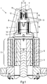
- FIG. 1 shows a preferred embodiment of a stirring head 1 of an agitator 2 according to the invention, which in FIG. 3 is completely shown, with a closed magnetic coupling 3.
- the agitator 2 comprises the stirring head 1, a drive unit 4, which in FIG. 3
- the magnetic coupling 3 includes drive magnets 5 and stirring magnet 6, wherein the Rlickkopfmagnete 6 are rigidly connected to the stirring head 1.
- the drive magnets 5 are in turn connected to the drive unit 4.
- the drive unit 4 sets the drive magnets 5, which are magnetically coupled to the Rlickkopfmagneten 6, in rotation.
- a rotational movement of the drive magnets 5 is transmitted to the Rloppykopfmagnete 6, and the stirring head 1 is rotated to mix a stirring medium.
- the stirring head 1 comprises stirring blades 7 and a bearing arrangement 8.
- the bearing arrangement 8 is constructed from a first rotation bearing 9 and a second rotation bearing 10, which are arranged at a distance from one another in the stirring head 1.
- the stirring vanes 7 establish a rigid connection of the stirring head magnets 6 with the first rotation bearing 9 and the second rotation bearing 10.
- the split construction of the bearing assembly 8 by means of the first rotary bearing 9 and the second rotary bearing 10 offers the advantage that loads received by the bearing assembly 8 are divided. This offers the advantage that in this way a higher stability, load capacity and service life of the bearing assembly 8 over the prior art is achieved.
- the first rotary bearing 9 is closer to the magnetic coupling 3 than the second rotary bearing 10th
- the stirring head 1 additionally allows the inclusion of an in FIG. 3 shown stirrer shaft 11 with arranged at this Rhackwellenhoffln 12 at the opposite end of the magnetic coupling 3 of the stirring head. 1
- the first rotary bearing 9 and the second rotary bearing 10 are designed in the preferred embodiment as a sliding bearing with sliding surfaces 13.
- the first rotary bearing 9 and the second rotary bearing 10 are hereby lubricated by the stirring medium, which is mixed by the agitator 2.
- This embodiment offers the advantage of a particularly simple and resistant construction of the stirring head 1, with a small number of moving parts. Furthermore, this structure facilitates disassembly of the stirring head 1 from the agitator 2.
- Particularly preferred is the design of the sliding surfaces 13 of ceramic materials, metallic materials, or polymer compounds such as PEEK, or any combination of these materials.
- the sliding surfaces 13 may additionally have a coating, such as a diamond coating. This offers the advantage of a particularly low wear.
- other forms of rotary bearings 9 and 10 such as ball bearings or roller bearings, can be used. Other forms of rotary bearings 9 and 10 will be apparent to those skilled in the art from this exemplary reference.
- first bearing gap 14 Between the sliding surfaces 13 of the first rotary bearing 9 is a first bearing gap 14, and between the sliding surfaces 13 of the second rotary bearing 10 there is a second bearing gap 15.
- These bearing gaps 14 and 15 have due to the construction of rotary bearings a circular cross section, which has a first bearing gap diameter 16 for the first rotary bearing 9 and a second bearing gap diameter 17 for the second rotary bearing 10 has.
- first rotary bearing 9 has a first width 18, and the second rotary bearing 10 has a second width 19, which represent the dimensions of the rotary bearings 9 and 10 normal to the bearing gap diameter 16 and 17.
- the first bearing gap diameter 16 differs from the second bearing gap diameter 17, and the first width 18 differs from the second width 19. This has the advantage that vibrations occurring on the stirring head 1 are absorbed by the second rotation bearing 10, and only steamed over the Rrindkopferiel 7 are delivered to the first rotary bearing 9. In addition, there is a load distribution within the camp order 8, which suppresses unwanted oscillation of the stirring head 1.
- the first width 18 and the first bearing gap diameter 16 larger than the second width 19 and the second bearing gap diameter 17. This ensures that at a load of the bearing assembly 8, the probability of bearing failure of the second rotation bearing 10 is higher than the probability This is advantageous because the second rotary bearing 10 has smaller dimensions than the first rotary bearing 9, and thus is cheaper to replace.
- FIG. 1 shown stirring head 1 allows, as already mentioned, the inclusion of in FIG. 3
- the above-mentioned ratios of the first width 18 and the second width 19, and the first bearing gap diameter 16 and the second bearing gap diameter 17 are particularly in the Use of long stirrer shafts 11 of advantage, at which stronger vibrations can occur to suppress unwanted oscillation of the stirring head 1.
- the first rotary bearing 9 is connected exclusively to the second rotary bearing 10 via the agitating blades 7. This offers the advantage of a particularly stable connection, at the same time low material usage and a damped vibration transmission between the rotary bearings 9 and 10.
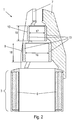
- FIG. 2 shows the stirring head 1 according to FIG. 1 , in a disassembled from the agitator 2 state.
- the magnetic coupling 3 was opened, wherein the drive magnets 5 were separated from the Rlickkopfmagneten 6. Furthermore, the sliding surfaces 13 of the first rotation bearing 9 and the second rotation bearing 10 were separated.
- FIG. 3 shows the agitator 2 according to the invention, installed in a stirred tank 20.
- the agitator 2 is installed on a container bottom of the stirred tank 20.
- the agitator 2 is installed on a container lid of the stirring container 20, which container lid can also be made detachable.
- the drive unit 4 is located outside of the stirred tank 20.
- the stirred tank 20 can be filled with the stirring medium, which can then be mixed by the rotational movement of the stirring head 1.
- the agitator 2 in FIG. 3 further comprises the stirring shaft 11, on which the stirring shaft wings 12 are arranged.
- the stirring shaft 11 is rigidly connected to the stirring head 1 and has the advantage that a homogeneous mixing of the stirring medium in the entire stirring container 20 is ensured by means of the stirring shaft blades 12.
- the inventive design of the agitator 2 offers the advantage of differently shaped stirring blades 7, and to apply stirrer shafts 11 with different lengths and Roughwellenhoffln 12.
- the agitator 2 according to the invention is made possible in a multiplicity of different forms of stirred containers 20 and, as in FIG FIG. 3 represented on the container bottom of the stirred tank 20 as well as on the container lid, in FIG. 3 not shown to install. This offers the advantage that the agitator 2 according to the invention can be used in a large number of different stirred containers 20.
Landscapes
- Chemical & Material Sciences (AREA)
- Chemical Kinetics & Catalysis (AREA)
- Engineering & Computer Science (AREA)
- General Engineering & Computer Science (AREA)
- Mechanical Engineering (AREA)
- Ceramic Engineering (AREA)
- Mixers With Rotating Receptacles And Mixers With Vibration Mechanisms (AREA)
- Accessories For Mixers (AREA)
- Mixers Of The Rotary Stirring Type (AREA)
- Food-Manufacturing Devices (AREA)
Applications Claiming Priority (1)
| Application Number | Priority Date | Filing Date | Title |
|---|---|---|---|
| ATA50053/2017A AT518668B1 (de) | 2017-01-25 | 2017-01-25 | Rührwerk für einen Rührbehälter |
Publications (2)
| Publication Number | Publication Date |
|---|---|
| EP3354334A1 true EP3354334A1 (fr) | 2018-08-01 |
| EP3354334B1 EP3354334B1 (fr) | 2021-06-09 |
Family
ID=60628627
Family Applications (1)
| Application Number | Title | Priority Date | Filing Date |
|---|---|---|---|
| EP18150945.6A Active EP3354334B1 (fr) | 2017-01-25 | 2018-01-10 | Agitateur pour une cuve mélangeuse |
Country Status (11)
| Country | Link |
|---|---|
| US (1) | US10682617B2 (fr) |
| EP (1) | EP3354334B1 (fr) |
| JP (1) | JP2018118243A (fr) |
| KR (1) | KR20180087856A (fr) |
| CN (1) | CN108339482A (fr) |
| AT (1) | AT518668B1 (fr) |
| CA (1) | CA2992188A1 (fr) |
| DK (1) | DK3354334T3 (fr) |
| HK (1) | HK1255607A1 (fr) |
| RU (1) | RU2018102605A (fr) |
| SG (1) | SG10201800425UA (fr) |
Families Citing this family (6)
| Publication number | Priority date | Publication date | Assignee | Title |
|---|---|---|---|---|
| AT518668B1 (de) * | 2017-01-25 | 2017-12-15 | Zeta Biopharma Gmbh | Rührwerk für einen Rührbehälter |
| US11065589B2 (en) * | 2018-12-10 | 2021-07-20 | Pall Corporation | Radially driven agitator |
| CN109647243A (zh) * | 2019-01-08 | 2019-04-19 | 浙江长城搅拌设备股份有限公司 | 密封管式搅拌轴支撑装置 |
| US11337438B2 (en) * | 2020-01-15 | 2022-05-24 | Coldsnap, Corp. | Rapidly cooling food and drinks |
| CN111701483A (zh) * | 2020-07-03 | 2020-09-25 | 付东梅 | 一种有机肥料混合装置 |
| CN117085547B (zh) * | 2023-10-18 | 2024-02-20 | 维达纸业(中国)有限公司 | 一种变频搅拌储浆罐 |
Citations (8)
| Publication number | Priority date | Publication date | Assignee | Title |
|---|---|---|---|---|
| JPS5439263A (en) * | 1977-09-02 | 1979-03-26 | Tsukishima Kikai Co | Sealless bottom drive type agitator |
| GB2185862A (en) * | 1985-12-11 | 1987-07-29 | Chem Plant Stainless Limited | Mixing vessel |
| GB2196800A (en) * | 1986-10-24 | 1988-05-05 | Christopher John Horseman | Electromagnetic mixer drive |
| DE20306404U1 (de) * | 2003-04-24 | 2003-06-26 | Mavag Verfahrenstechnik Ag Neu | Mehrrühreranordnung |
| EP1748201A2 (fr) * | 2005-07-29 | 2007-01-31 | Zeta AG Bio- und Verfahrenstechnik | Mélangeur magnétique |
| US20070053238A1 (en) * | 2005-09-07 | 2007-03-08 | Spx Corporation | Disposable sanitary mixing apparatus and method |
| EP2286907A1 (fr) * | 2009-08-20 | 2011-02-23 | Patrice Grayel | Dispositif pour réaliser l'agitation d'un milieu liquide |
| DE102015000704B3 (de) * | 2015-01-20 | 2016-01-21 | Sartorius Stedim Biotech Gmbh | Mischvorrichtung mit einem Rührelement, eine Antriebsvorrichtung zum Antreiben eines Rührelements in einer Mischvorrichtung, ein Mischvorrichtungssystem und ein Verfahren zum Antreiben eines Rührelements in einer Mischvorrichtung |
Family Cites Families (23)
| Publication number | Priority date | Publication date | Assignee | Title |
|---|---|---|---|---|
| US4209259A (en) * | 1978-11-01 | 1980-06-24 | Rains Robert L | Magnetic mixer |
| DE2945678A1 (de) * | 1979-11-12 | 1981-05-27 | Basf Ag, 6700 Ludwigshafen | Freitragender ruehrer zum durchmischen eines schuettgutbettes |
| US4993841A (en) * | 1987-02-05 | 1991-02-19 | Steridose Systems Ab | Magnetic impeller means for a mixing vessel |
| SE463750B (sv) * | 1989-05-26 | 1991-01-21 | Steridose Systems Ab | Omroerare foer aseptiska aendamaal, vilken aer vridbar i en foerutbestaemd rotationsriktning genom induktiva drivorgan inuti en tank |
| DE4232934C2 (de) * | 1992-10-01 | 1996-03-28 | Mavag Verfahrenstech Ag | Doppel-Impeller zum Rühren von sterilen Flüssigkeiten |
| DE4232936C2 (de) * | 1992-10-01 | 1996-03-28 | Mavag Verfahrenstech Ag | Impeller zum Rühren von sterilen Flüssigkeiten |
| DE4235498A1 (de) * | 1992-10-21 | 1994-04-28 | Herfeld Gmbh & Co Kg Dr | Mischvorrichtung |
| US5470152A (en) * | 1993-02-23 | 1995-11-28 | General Signal Corporation | Radially mounted magnetic coupling |
| US5779359A (en) * | 1996-12-05 | 1998-07-14 | General Signal Corporation | Mixer having exposed clean-in-place bearing assemblies |
| US5758965A (en) * | 1996-12-05 | 1998-06-02 | General Signal Corporation | Mixer system |
| FR2788995B1 (fr) * | 1999-01-28 | 2001-04-06 | Mixel | Agitateur a entrainement magnetique et procede du reglage du couple limite de transmission d'effort d'un tel agitateur |
| FR2779361B1 (fr) * | 1998-06-05 | 2000-07-28 | Mixel | Agitateur a entrainement magnetique |
| US7762716B2 (en) * | 2000-10-09 | 2010-07-27 | Levtech, Inc. | Mixing vessel with a fluid-agitating element supported by a roller bearing |
| US6854877B2 (en) * | 2002-10-16 | 2005-02-15 | Aseptic Controls Investment Co. | Mixer for aseptic liquids |
| JP2007522801A (ja) * | 2004-01-07 | 2007-08-16 | リーブテック,インコーポレイテッド | 一体のスパージャーとセンサー受け器を有する混合用袋 |
| US7396153B2 (en) * | 2005-04-05 | 2008-07-08 | Andersson Per-Olof K | Ultraclean magnetic mixer |
| US20070286015A1 (en) * | 2006-06-08 | 2007-12-13 | Spx Corporation | Magnetic mixer drive system and method |
| JP5480392B2 (ja) * | 2009-10-21 | 2014-04-23 | メテノヴァ ホールディング, エービー | 攪拌装置 |
| CN201676660U (zh) * | 2010-04-27 | 2010-12-22 | 成都英德生物工程有限公司 | 一种具有在线清洗灭菌功能的磁力驱动搅拌轴 |
| US9565970B2 (en) * | 2011-04-14 | 2017-02-14 | Electrodomesticos Taurus Sl | Cooking system including a cooking hob and a cooking vessel |
| US10519409B2 (en) * | 2014-12-31 | 2019-12-31 | Ge Healthcare Bio-Sciences Corp. | Shaft-mounted fluid transfer assembly for a disposable bioreactor |
| AT518668B1 (de) * | 2017-01-25 | 2017-12-15 | Zeta Biopharma Gmbh | Rührwerk für einen Rührbehälter |
| AT520184B1 (de) * | 2017-09-18 | 2019-02-15 | Zeta Biopharma Gmbh | Rührkopf mit Identifikationsvorrichtung |
-
2017
- 2017-01-25 AT ATA50053/2017A patent/AT518668B1/de active
-
2018
- 2018-01-10 EP EP18150945.6A patent/EP3354334B1/fr active Active
- 2018-01-10 DK DK18150945.6T patent/DK3354334T3/da active
- 2018-01-17 SG SG10201800425UA patent/SG10201800425UA/en unknown
- 2018-01-17 CA CA2992188A patent/CA2992188A1/fr not_active Abandoned
- 2018-01-22 US US15/876,721 patent/US10682617B2/en active Active
- 2018-01-23 JP JP2018009109A patent/JP2018118243A/ja active Pending
- 2018-01-23 CN CN201810062588.1A patent/CN108339482A/zh active Pending
- 2018-01-23 KR KR1020180008299A patent/KR20180087856A/ko not_active Withdrawn
- 2018-01-24 RU RU2018102605A patent/RU2018102605A/ru not_active Application Discontinuation
- 2018-11-19 HK HK18114737.9A patent/HK1255607A1/zh unknown
Patent Citations (8)
| Publication number | Priority date | Publication date | Assignee | Title |
|---|---|---|---|---|
| JPS5439263A (en) * | 1977-09-02 | 1979-03-26 | Tsukishima Kikai Co | Sealless bottom drive type agitator |
| GB2185862A (en) * | 1985-12-11 | 1987-07-29 | Chem Plant Stainless Limited | Mixing vessel |
| GB2196800A (en) * | 1986-10-24 | 1988-05-05 | Christopher John Horseman | Electromagnetic mixer drive |
| DE20306404U1 (de) * | 2003-04-24 | 2003-06-26 | Mavag Verfahrenstechnik Ag Neu | Mehrrühreranordnung |
| EP1748201A2 (fr) * | 2005-07-29 | 2007-01-31 | Zeta AG Bio- und Verfahrenstechnik | Mélangeur magnétique |
| US20070053238A1 (en) * | 2005-09-07 | 2007-03-08 | Spx Corporation | Disposable sanitary mixing apparatus and method |
| EP2286907A1 (fr) * | 2009-08-20 | 2011-02-23 | Patrice Grayel | Dispositif pour réaliser l'agitation d'un milieu liquide |
| DE102015000704B3 (de) * | 2015-01-20 | 2016-01-21 | Sartorius Stedim Biotech Gmbh | Mischvorrichtung mit einem Rührelement, eine Antriebsvorrichtung zum Antreiben eines Rührelements in einer Mischvorrichtung, ein Mischvorrichtungssystem und ein Verfahren zum Antreiben eines Rührelements in einer Mischvorrichtung |
Also Published As
| Publication number | Publication date |
|---|---|
| RU2018102605A (ru) | 2019-07-25 |
| JP2018118243A (ja) | 2018-08-02 |
| AT518668B1 (de) | 2017-12-15 |
| KR20180087856A (ko) | 2018-08-02 |
| CN108339482A (zh) | 2018-07-31 |
| AT518668A4 (de) | 2017-12-15 |
| EP3354334B1 (fr) | 2021-06-09 |
| DK3354334T3 (da) | 2021-08-23 |
| SG10201800425UA (en) | 2018-08-30 |
| US20180207593A1 (en) | 2018-07-26 |
| HK1255607A1 (zh) | 2019-08-23 |
| CA2992188A1 (fr) | 2018-07-25 |
| US10682617B2 (en) | 2020-06-16 |
Similar Documents
| Publication | Publication Date | Title |
|---|---|---|
| EP3354334B1 (fr) | Agitateur pour une cuve mélangeuse | |
| DE102008064815B3 (de) | Spindelmotor mit fluiddynamischem Lagersystem und feststehender WeIle | |
| EP0516921A1 (fr) | Agitateur de gazage | |
| EP1921322A2 (fr) | Module du palier pour une pompe à vide | |
| DE4014170A1 (de) | Moineau-pumpe mit endseitig verschlossenem rotierendem aussenteil und nichtrotierendem hohlem innnenteil | |
| EP3288674B1 (fr) | Système d'organe d'agitation | |
| EP4132694A1 (fr) | Procédé et dispositif à élément d'agitation pour mélanger des fluides et/ou des pâtes moyennement visqueux à très visqueux | |
| EP2539061B1 (fr) | Mélangeur | |
| EP1470856A1 (fr) | Agitateur pur mélanger, homogénéiser et disperser | |
| EP2872816B1 (fr) | Raccord de bras de support | |
| DE102009039120A1 (de) | Vakuumpumpe | |
| EP2179188B1 (fr) | Palier lisse et réacteur équipé de ce dernier | |
| CH719393A2 (de) | Labor-Mischkneter. | |
| DE20114076U1 (de) | Homogenisator, insbesondere für den Boden eines Misch- und Rührbehälters | |
| EP3091647A1 (fr) | Unité d'entraînement d'un agitateur et agitateur | |
| DE102017007557B4 (de) | Mischvorrichtung und Verfahren zum Betreiben einer Mischvorrichtung | |
| DE102015215308A1 (de) | Flüssigmetall-Gleitlager | |
| DE102011084053A1 (de) | Mischer mit Zerkleinerungs- und Dispergiervorrichtung | |
| EP3844392B1 (fr) | Ensemble de paliers pour une eolienne et eolienne | |
| WO2007012404A1 (fr) | Agitateur pour realiser une polycondensation de masse en fusion comprenant un rotor double et un palier de rotor interne au reacteur, lubrifie par produit | |
| DE10217515A1 (de) | Rührvorrichtung zum Auflösen von Schlieren in einer Glasschmelze | |
| DD253486A1 (de) | Rotationsviskosimeter zur bestimmung der viskositaet fliessfaehiger medien | |
| DE102005049373A1 (de) | Lagervorrichtung für ein Rührwerk | |
| DE10161180B4 (de) | Mischvorrichtung zum Mischen von mindestens zwei flüssigen Komponenten | |
| DE3810687A1 (de) | Wellendurchfuehrung |
Legal Events
| Date | Code | Title | Description |
|---|---|---|---|
| PUAI | Public reference made under article 153(3) epc to a published international application that has entered the european phase |
Free format text: ORIGINAL CODE: 0009012 |
|
| STAA | Information on the status of an ep patent application or granted ep patent |
Free format text: STATUS: THE APPLICATION HAS BEEN PUBLISHED |
|
| AK | Designated contracting states |
Kind code of ref document: A1 Designated state(s): AL AT BE BG CH CY CZ DE DK EE ES FI FR GB GR HR HU IE IS IT LI LT LU LV MC MK MT NL NO PL PT RO RS SE SI SK SM TR |
|
| AX | Request for extension of the european patent |
Extension state: BA ME |
|
| STAA | Information on the status of an ep patent application or granted ep patent |
Free format text: STATUS: REQUEST FOR EXAMINATION WAS MADE |
|
| 17P | Request for examination filed |
Effective date: 20180820 |
|
| RBV | Designated contracting states (corrected) |
Designated state(s): AL AT BE BG CH CY CZ DE DK EE ES FI FR GB GR HR HU IE IS IT LI LT LU LV MC MK MT NL NO PL PT RO RS SE SI SK SM TR |
|
| GRAP | Despatch of communication of intention to grant a patent |
Free format text: ORIGINAL CODE: EPIDOSNIGR1 |
|
| STAA | Information on the status of an ep patent application or granted ep patent |
Free format text: STATUS: GRANT OF PATENT IS INTENDED |
|
| INTG | Intention to grant announced |
Effective date: 20210128 |
|
| GRAS | Grant fee paid |
Free format text: ORIGINAL CODE: EPIDOSNIGR3 |
|
| GRAA | (expected) grant |
Free format text: ORIGINAL CODE: 0009210 |
|
| STAA | Information on the status of an ep patent application or granted ep patent |
Free format text: STATUS: THE PATENT HAS BEEN GRANTED |
|
| AK | Designated contracting states |
Kind code of ref document: B1 Designated state(s): AL AT BE BG CH CY CZ DE DK EE ES FI FR GB GR HR HU IE IS IT LI LT LU LV MC MK MT NL NO PL PT RO RS SE SI SK SM TR |
|
| REG | Reference to a national code |
Ref country code: GB Ref legal event code: FG4D Free format text: NOT ENGLISH |
|
| REG | Reference to a national code |
Ref country code: AT Ref legal event code: REF Ref document number: 1400002 Country of ref document: AT Kind code of ref document: T Effective date: 20210615 Ref country code: CH Ref legal event code: EP |
|
| REG | Reference to a national code |
Ref country code: DE Ref legal event code: R096 Ref document number: 502018005577 Country of ref document: DE |
|
| REG | Reference to a national code |
Ref country code: IE Ref legal event code: FG4D Free format text: LANGUAGE OF EP DOCUMENT: GERMAN |
|
| REG | Reference to a national code |
Ref country code: DK Ref legal event code: T3 Effective date: 20210820 |
|
| REG | Reference to a national code |
Ref country code: SE Ref legal event code: TRGR |
|
| REG | Reference to a national code |
Ref country code: NL Ref legal event code: FP |
|
| REG | Reference to a national code |
Ref country code: LT Ref legal event code: MG9D |
|
| PG25 | Lapsed in a contracting state [announced via postgrant information from national office to epo] |
Ref country code: BG Free format text: LAPSE BECAUSE OF FAILURE TO SUBMIT A TRANSLATION OF THE DESCRIPTION OR TO PAY THE FEE WITHIN THE PRESCRIBED TIME-LIMIT Effective date: 20210909 Ref country code: HR Free format text: LAPSE BECAUSE OF FAILURE TO SUBMIT A TRANSLATION OF THE DESCRIPTION OR TO PAY THE FEE WITHIN THE PRESCRIBED TIME-LIMIT Effective date: 20210609 Ref country code: LT Free format text: LAPSE BECAUSE OF FAILURE TO SUBMIT A TRANSLATION OF THE DESCRIPTION OR TO PAY THE FEE WITHIN THE PRESCRIBED TIME-LIMIT Effective date: 20210609 Ref country code: FI Free format text: LAPSE BECAUSE OF FAILURE TO SUBMIT A TRANSLATION OF THE DESCRIPTION OR TO PAY THE FEE WITHIN THE PRESCRIBED TIME-LIMIT Effective date: 20210609 |
|
| REG | Reference to a national code |
Ref country code: DE Ref legal event code: R079 Ref document number: 502018005577 Country of ref document: DE Free format text: PREVIOUS MAIN CLASS: B01F0013080000 Ipc: B01F0033450000 |
|
| PG25 | Lapsed in a contracting state [announced via postgrant information from national office to epo] |
Ref country code: GR Free format text: LAPSE BECAUSE OF FAILURE TO SUBMIT A TRANSLATION OF THE DESCRIPTION OR TO PAY THE FEE WITHIN THE PRESCRIBED TIME-LIMIT Effective date: 20210910 Ref country code: NO Free format text: LAPSE BECAUSE OF FAILURE TO SUBMIT A TRANSLATION OF THE DESCRIPTION OR TO PAY THE FEE WITHIN THE PRESCRIBED TIME-LIMIT Effective date: 20210909 Ref country code: LV Free format text: LAPSE BECAUSE OF FAILURE TO SUBMIT A TRANSLATION OF THE DESCRIPTION OR TO PAY THE FEE WITHIN THE PRESCRIBED TIME-LIMIT Effective date: 20210609 Ref country code: RS Free format text: LAPSE BECAUSE OF FAILURE TO SUBMIT A TRANSLATION OF THE DESCRIPTION OR TO PAY THE FEE WITHIN THE PRESCRIBED TIME-LIMIT Effective date: 20210609 |
|
| PG25 | Lapsed in a contracting state [announced via postgrant information from national office to epo] |
Ref country code: EE Free format text: LAPSE BECAUSE OF FAILURE TO SUBMIT A TRANSLATION OF THE DESCRIPTION OR TO PAY THE FEE WITHIN THE PRESCRIBED TIME-LIMIT Effective date: 20210609 Ref country code: ES Free format text: LAPSE BECAUSE OF FAILURE TO SUBMIT A TRANSLATION OF THE DESCRIPTION OR TO PAY THE FEE WITHIN THE PRESCRIBED TIME-LIMIT Effective date: 20210609 Ref country code: SK Free format text: LAPSE BECAUSE OF FAILURE TO SUBMIT A TRANSLATION OF THE DESCRIPTION OR TO PAY THE FEE WITHIN THE PRESCRIBED TIME-LIMIT Effective date: 20210609 Ref country code: SM Free format text: LAPSE BECAUSE OF FAILURE TO SUBMIT A TRANSLATION OF THE DESCRIPTION OR TO PAY THE FEE WITHIN THE PRESCRIBED TIME-LIMIT Effective date: 20210609 Ref country code: PT Free format text: LAPSE BECAUSE OF FAILURE TO SUBMIT A TRANSLATION OF THE DESCRIPTION OR TO PAY THE FEE WITHIN THE PRESCRIBED TIME-LIMIT Effective date: 20211011 Ref country code: RO Free format text: LAPSE BECAUSE OF FAILURE TO SUBMIT A TRANSLATION OF THE DESCRIPTION OR TO PAY THE FEE WITHIN THE PRESCRIBED TIME-LIMIT Effective date: 20210609 Ref country code: CZ Free format text: LAPSE BECAUSE OF FAILURE TO SUBMIT A TRANSLATION OF THE DESCRIPTION OR TO PAY THE FEE WITHIN THE PRESCRIBED TIME-LIMIT Effective date: 20210609 |
|
| PG25 | Lapsed in a contracting state [announced via postgrant information from national office to epo] |
Ref country code: PL Free format text: LAPSE BECAUSE OF FAILURE TO SUBMIT A TRANSLATION OF THE DESCRIPTION OR TO PAY THE FEE WITHIN THE PRESCRIBED TIME-LIMIT Effective date: 20210609 |
|
| REG | Reference to a national code |
Ref country code: DE Ref legal event code: R097 Ref document number: 502018005577 Country of ref document: DE |
|
| PLBE | No opposition filed within time limit |
Free format text: ORIGINAL CODE: 0009261 |
|
| STAA | Information on the status of an ep patent application or granted ep patent |
Free format text: STATUS: NO OPPOSITION FILED WITHIN TIME LIMIT |
|
| 26N | No opposition filed |
Effective date: 20220310 |
|
| PG25 | Lapsed in a contracting state [announced via postgrant information from national office to epo] |
Ref country code: AL Free format text: LAPSE BECAUSE OF FAILURE TO SUBMIT A TRANSLATION OF THE DESCRIPTION OR TO PAY THE FEE WITHIN THE PRESCRIBED TIME-LIMIT Effective date: 20210609 |
|
| PG25 | Lapsed in a contracting state [announced via postgrant information from national office to epo] |
Ref country code: IT Free format text: LAPSE BECAUSE OF FAILURE TO SUBMIT A TRANSLATION OF THE DESCRIPTION OR TO PAY THE FEE WITHIN THE PRESCRIBED TIME-LIMIT Effective date: 20210609 |
|
| PG25 | Lapsed in a contracting state [announced via postgrant information from national office to epo] |
Ref country code: MC Free format text: LAPSE BECAUSE OF FAILURE TO SUBMIT A TRANSLATION OF THE DESCRIPTION OR TO PAY THE FEE WITHIN THE PRESCRIBED TIME-LIMIT Effective date: 20210609 |
|
| PG25 | Lapsed in a contracting state [announced via postgrant information from national office to epo] |
Ref country code: LU Free format text: LAPSE BECAUSE OF NON-PAYMENT OF DUE FEES Effective date: 20220110 |
|
| REG | Reference to a national code |
Ref country code: AT Ref legal event code: MM01 Ref document number: 1400002 Country of ref document: AT Kind code of ref document: T Effective date: 20230110 |
|
| PG25 | Lapsed in a contracting state [announced via postgrant information from national office to epo] |
Ref country code: HU Free format text: LAPSE BECAUSE OF FAILURE TO SUBMIT A TRANSLATION OF THE DESCRIPTION OR TO PAY THE FEE WITHIN THE PRESCRIBED TIME-LIMIT; INVALID AB INITIO Effective date: 20180110 |
|
| PG25 | Lapsed in a contracting state [announced via postgrant information from national office to epo] |
Ref country code: AT Free format text: LAPSE BECAUSE OF NON-PAYMENT OF DUE FEES Effective date: 20230110 |
|
| PG25 | Lapsed in a contracting state [announced via postgrant information from national office to epo] |
Ref country code: MK Free format text: LAPSE BECAUSE OF FAILURE TO SUBMIT A TRANSLATION OF THE DESCRIPTION OR TO PAY THE FEE WITHIN THE PRESCRIBED TIME-LIMIT Effective date: 20210609 Ref country code: CY Free format text: LAPSE BECAUSE OF FAILURE TO SUBMIT A TRANSLATION OF THE DESCRIPTION OR TO PAY THE FEE WITHIN THE PRESCRIBED TIME-LIMIT Effective date: 20210609 Ref country code: AT Free format text: LAPSE BECAUSE OF NON-PAYMENT OF DUE FEES Effective date: 20230110 |
|
| PG25 | Lapsed in a contracting state [announced via postgrant information from national office to epo] |
Ref country code: TR Free format text: LAPSE BECAUSE OF FAILURE TO SUBMIT A TRANSLATION OF THE DESCRIPTION OR TO PAY THE FEE WITHIN THE PRESCRIBED TIME-LIMIT Effective date: 20210609 |
|
| PG25 | Lapsed in a contracting state [announced via postgrant information from national office to epo] |
Ref country code: MT Free format text: LAPSE BECAUSE OF FAILURE TO SUBMIT A TRANSLATION OF THE DESCRIPTION OR TO PAY THE FEE WITHIN THE PRESCRIBED TIME-LIMIT Effective date: 20210609 |
|
| REG | Reference to a national code |
Ref country code: CH Ref legal event code: U11 Free format text: ST27 STATUS EVENT CODE: U-0-0-U10-U11 (AS PROVIDED BY THE NATIONAL OFFICE) Effective date: 20260201 |
|
| PGFP | Annual fee paid to national office [announced via postgrant information from national office to epo] |
Ref country code: NL Payment date: 20260121 Year of fee payment: 9 |
|
| PGFP | Annual fee paid to national office [announced via postgrant information from national office to epo] |
Ref country code: SE Payment date: 20260121 Year of fee payment: 9 |
|
| PGFP | Annual fee paid to national office [announced via postgrant information from national office to epo] |
Ref country code: GB Payment date: 20260122 Year of fee payment: 9 |
|
| PGFP | Annual fee paid to national office [announced via postgrant information from national office to epo] |
Ref country code: DE Payment date: 20260120 Year of fee payment: 9 Ref country code: DK Payment date: 20260121 Year of fee payment: 9 Ref country code: IE Payment date: 20260121 Year of fee payment: 9 |
|
| PGFP | Annual fee paid to national office [announced via postgrant information from national office to epo] |
Ref country code: AT Payment date: 20260410 Year of fee payment: 5 |
|
| PGFP | Annual fee paid to national office [announced via postgrant information from national office to epo] |
Ref country code: BE Payment date: 20260121 Year of fee payment: 9 |
|
| PGFP | Annual fee paid to national office [announced via postgrant information from national office to epo] |
Ref country code: FR Payment date: 20260121 Year of fee payment: 9 |
|
| PGFP | Annual fee paid to national office [announced via postgrant information from national office to epo] |
Ref country code: CH Payment date: 20260201 Year of fee payment: 9 |