EP3354337B1 - Procédé de fabrication d'un granulé de mousse metallique, granulé de mousse metallique, remplissage de catalyseur et mélangeur statique - Google Patents
Procédé de fabrication d'un granulé de mousse metallique, granulé de mousse metallique, remplissage de catalyseur et mélangeur statique Download PDFInfo
- Publication number
- EP3354337B1 EP3354337B1 EP17154045.3A EP17154045A EP3354337B1 EP 3354337 B1 EP3354337 B1 EP 3354337B1 EP 17154045 A EP17154045 A EP 17154045A EP 3354337 B1 EP3354337 B1 EP 3354337B1
- Authority
- EP
- European Patent Office
- Prior art keywords
- pellet
- metal foam
- pellets
- accordance
- pores
- Prior art date
- Legal status (The legal status is an assumption and is not a legal conclusion. Google has not performed a legal analysis and makes no representation as to the accuracy of the status listed.)
- Active
Links
Images


Classifications
-
- B—PERFORMING OPERATIONS; TRANSPORTING
- B01—PHYSICAL OR CHEMICAL PROCESSES OR APPARATUS IN GENERAL
- B01J—CHEMICAL OR PHYSICAL PROCESSES, e.g. CATALYSIS OR COLLOID CHEMISTRY; THEIR RELEVANT APPARATUS
- B01J19/00—Chemical, physical or physico-chemical processes in general; Their relevant apparatus
- B01J19/24—Stationary reactors without moving elements inside
-
- B—PERFORMING OPERATIONS; TRANSPORTING
- B01—PHYSICAL OR CHEMICAL PROCESSES OR APPARATUS IN GENERAL
- B01J—CHEMICAL OR PHYSICAL PROCESSES, e.g. CATALYSIS OR COLLOID CHEMISTRY; THEIR RELEVANT APPARATUS
- B01J25/00—Catalysts of the Raney type
- B01J25/02—Raney nickel
-
- B—PERFORMING OPERATIONS; TRANSPORTING
- B01—PHYSICAL OR CHEMICAL PROCESSES OR APPARATUS IN GENERAL
- B01J—CHEMICAL OR PHYSICAL PROCESSES, e.g. CATALYSIS OR COLLOID CHEMISTRY; THEIR RELEVANT APPARATUS
- B01J37/00—Processes, in general, for preparing catalysts; Processes, in general, for activation of catalysts
- B01J37/0009—Use of binding agents; Moulding; Pressing; Powdering; Granulating; Addition of materials ameliorating the mechanical properties of the product catalyst
-
- B—PERFORMING OPERATIONS; TRANSPORTING
- B01—PHYSICAL OR CHEMICAL PROCESSES OR APPARATUS IN GENERAL
- B01J—CHEMICAL OR PHYSICAL PROCESSES, e.g. CATALYSIS OR COLLOID CHEMISTRY; THEIR RELEVANT APPARATUS
- B01J19/00—Chemical, physical or physico-chemical processes in general; Their relevant apparatus
- B01J19/30—Loose or shaped packing elements, e.g. Raschig rings or Berl saddles, for pouring into the apparatus for mass or heat transfer
-
- B—PERFORMING OPERATIONS; TRANSPORTING
- B01—PHYSICAL OR CHEMICAL PROCESSES OR APPARATUS IN GENERAL
- B01J—CHEMICAL OR PHYSICAL PROCESSES, e.g. CATALYSIS OR COLLOID CHEMISTRY; THEIR RELEVANT APPARATUS
- B01J23/00—Catalysts comprising metals or metal oxides or hydroxides, not provided for in group B01J21/00
- B01J23/70—Catalysts comprising metals or metal oxides or hydroxides, not provided for in group B01J21/00 of the iron group metals or copper
- B01J23/76—Catalysts comprising metals or metal oxides or hydroxides, not provided for in group B01J21/00 of the iron group metals or copper combined with metals, oxides or hydroxides provided for in groups B01J23/02 - B01J23/36
- B01J23/84—Catalysts comprising metals or metal oxides or hydroxides, not provided for in group B01J21/00 of the iron group metals or copper combined with metals, oxides or hydroxides provided for in groups B01J23/02 - B01J23/36 with arsenic, antimony, bismuth, vanadium, niobium, tantalum, polonium, chromium, molybdenum, tungsten, manganese, technetium or rhenium
- B01J23/85—Chromium, molybdenum or tungsten
- B01J23/86—Chromium
- B01J23/866—Nickel and chromium
-
- B—PERFORMING OPERATIONS; TRANSPORTING
- B01—PHYSICAL OR CHEMICAL PROCESSES OR APPARATUS IN GENERAL
- B01J—CHEMICAL OR PHYSICAL PROCESSES, e.g. CATALYSIS OR COLLOID CHEMISTRY; THEIR RELEVANT APPARATUS
- B01J35/00—Catalysts, in general, characterised by their form or physical properties
- B01J35/30—Catalysts, in general, characterised by their form or physical properties characterised by their physical properties
-
- B—PERFORMING OPERATIONS; TRANSPORTING
- B01—PHYSICAL OR CHEMICAL PROCESSES OR APPARATUS IN GENERAL
- B01J—CHEMICAL OR PHYSICAL PROCESSES, e.g. CATALYSIS OR COLLOID CHEMISTRY; THEIR RELEVANT APPARATUS
- B01J35/00—Catalysts, in general, characterised by their form or physical properties
- B01J35/40—Catalysts, in general, characterised by their form or physical properties characterised by dimensions, e.g. grain size
-
- B—PERFORMING OPERATIONS; TRANSPORTING
- B01—PHYSICAL OR CHEMICAL PROCESSES OR APPARATUS IN GENERAL
- B01J—CHEMICAL OR PHYSICAL PROCESSES, e.g. CATALYSIS OR COLLOID CHEMISTRY; THEIR RELEVANT APPARATUS
- B01J35/00—Catalysts, in general, characterised by their form or physical properties
- B01J35/50—Catalysts, in general, characterised by their form or physical properties characterised by their shape or configuration
-
- B—PERFORMING OPERATIONS; TRANSPORTING
- B01—PHYSICAL OR CHEMICAL PROCESSES OR APPARATUS IN GENERAL
- B01J—CHEMICAL OR PHYSICAL PROCESSES, e.g. CATALYSIS OR COLLOID CHEMISTRY; THEIR RELEVANT APPARATUS
- B01J35/00—Catalysts, in general, characterised by their form or physical properties
- B01J35/60—Catalysts, in general, characterised by their form or physical properties characterised by their surface properties or porosity
- B01J35/64—Pore diameter
- B01J35/657—Pore diameter larger than 1000 nm
-
- B—PERFORMING OPERATIONS; TRANSPORTING
- B01—PHYSICAL OR CHEMICAL PROCESSES OR APPARATUS IN GENERAL
- B01J—CHEMICAL OR PHYSICAL PROCESSES, e.g. CATALYSIS OR COLLOID CHEMISTRY; THEIR RELEVANT APPARATUS
- B01J35/00—Catalysts, in general, characterised by their form or physical properties
- B01J35/60—Catalysts, in general, characterised by their form or physical properties characterised by their surface properties or porosity
- B01J35/66—Pore distribution
- B01J35/67—Pore distribution monomodal
-
- B—PERFORMING OPERATIONS; TRANSPORTING
- B01—PHYSICAL OR CHEMICAL PROCESSES OR APPARATUS IN GENERAL
- B01J—CHEMICAL OR PHYSICAL PROCESSES, e.g. CATALYSIS OR COLLOID CHEMISTRY; THEIR RELEVANT APPARATUS
- B01J35/00—Catalysts, in general, characterised by their form or physical properties
- B01J35/60—Catalysts, in general, characterised by their form or physical properties characterised by their surface properties or porosity
- B01J35/66—Pore distribution
- B01J35/69—Pore distribution bimodal
-
- B—PERFORMING OPERATIONS; TRANSPORTING
- B01—PHYSICAL OR CHEMICAL PROCESSES OR APPARATUS IN GENERAL
- B01J—CHEMICAL OR PHYSICAL PROCESSES, e.g. CATALYSIS OR COLLOID CHEMISTRY; THEIR RELEVANT APPARATUS
- B01J35/00—Catalysts, in general, characterised by their form or physical properties
- B01J35/60—Catalysts, in general, characterised by their form or physical properties characterised by their surface properties or porosity
- B01J35/66—Pore distribution
- B01J35/695—Pore distribution polymodal
-
- B—PERFORMING OPERATIONS; TRANSPORTING
- B22—CASTING; POWDER METALLURGY
- B22F—WORKING METALLIC POWDER; MANUFACTURE OF ARTICLES FROM METALLIC POWDER; MAKING METALLIC POWDER; APPARATUS OR DEVICES SPECIALLY ADAPTED FOR METALLIC POWDER
- B22F3/00—Manufacture of workpieces or articles from metallic powder characterised by the manner of compacting or sintering; Apparatus specially adapted therefor ; Presses and furnaces
- B22F3/22—Manufacture of workpieces or articles from metallic powder characterised by the manner of compacting or sintering; Apparatus specially adapted therefor ; Presses and furnaces for producing castings from a slip
-
- C—CHEMISTRY; METALLURGY
- C22—METALLURGY; FERROUS OR NON-FERROUS ALLOYS; TREATMENT OF ALLOYS OR NON-FERROUS METALS
- C22C—ALLOYS
- C22C1/00—Making non-ferrous alloys
- C22C1/08—Alloys with open or closed pores
-
- B—PERFORMING OPERATIONS; TRANSPORTING
- B01—PHYSICAL OR CHEMICAL PROCESSES OR APPARATUS IN GENERAL
- B01J—CHEMICAL OR PHYSICAL PROCESSES, e.g. CATALYSIS OR COLLOID CHEMISTRY; THEIR RELEVANT APPARATUS
- B01J2219/00—Chemical, physical or physico-chemical processes in general; Their relevant apparatus
- B01J2219/30—Details relating to random packing elements
- B01J2219/302—Basic shape of the elements
- B01J2219/30203—Saddle
-
- B—PERFORMING OPERATIONS; TRANSPORTING
- B01—PHYSICAL OR CHEMICAL PROCESSES OR APPARATUS IN GENERAL
- B01J—CHEMICAL OR PHYSICAL PROCESSES, e.g. CATALYSIS OR COLLOID CHEMISTRY; THEIR RELEVANT APPARATUS
- B01J2219/00—Chemical, physical or physico-chemical processes in general; Their relevant apparatus
- B01J2219/30—Details relating to random packing elements
- B01J2219/302—Basic shape of the elements
- B01J2219/30215—Toroid or ring
-
- B—PERFORMING OPERATIONS; TRANSPORTING
- B01—PHYSICAL OR CHEMICAL PROCESSES OR APPARATUS IN GENERAL
- B01J—CHEMICAL OR PHYSICAL PROCESSES, e.g. CATALYSIS OR COLLOID CHEMISTRY; THEIR RELEVANT APPARATUS
- B01J2219/00—Chemical, physical or physico-chemical processes in general; Their relevant apparatus
- B01J2219/30—Details relating to random packing elements
- B01J2219/302—Basic shape of the elements
- B01J2219/30242—Star
-
- B—PERFORMING OPERATIONS; TRANSPORTING
- B01—PHYSICAL OR CHEMICAL PROCESSES OR APPARATUS IN GENERAL
- B01J—CHEMICAL OR PHYSICAL PROCESSES, e.g. CATALYSIS OR COLLOID CHEMISTRY; THEIR RELEVANT APPARATUS
- B01J2219/00—Chemical, physical or physico-chemical processes in general; Their relevant apparatus
- B01J2219/30—Details relating to random packing elements
- B01J2219/302—Basic shape of the elements
- B01J2219/30276—Sheet
- B01J2219/30284—Sheet twisted
-
- B—PERFORMING OPERATIONS; TRANSPORTING
- B01—PHYSICAL OR CHEMICAL PROCESSES OR APPARATUS IN GENERAL
- B01J—CHEMICAL OR PHYSICAL PROCESSES, e.g. CATALYSIS OR COLLOID CHEMISTRY; THEIR RELEVANT APPARATUS
- B01J2219/00—Chemical, physical or physico-chemical processes in general; Their relevant apparatus
- B01J2219/30—Details relating to random packing elements
- B01J2219/302—Basic shape of the elements
- B01J2219/30276—Sheet
- B01J2219/30292—Sheet rolled up
-
- B—PERFORMING OPERATIONS; TRANSPORTING
- B01—PHYSICAL OR CHEMICAL PROCESSES OR APPARATUS IN GENERAL
- B01J—CHEMICAL OR PHYSICAL PROCESSES, e.g. CATALYSIS OR COLLOID CHEMISTRY; THEIR RELEVANT APPARATUS
- B01J2219/00—Chemical, physical or physico-chemical processes in general; Their relevant apparatus
- B01J2219/30—Details relating to random packing elements
- B01J2219/302—Basic shape of the elements
- B01J2219/30296—Other shapes
-
- B—PERFORMING OPERATIONS; TRANSPORTING
- B01—PHYSICAL OR CHEMICAL PROCESSES OR APPARATUS IN GENERAL
- B01J—CHEMICAL OR PHYSICAL PROCESSES, e.g. CATALYSIS OR COLLOID CHEMISTRY; THEIR RELEVANT APPARATUS
- B01J2219/00—Chemical, physical or physico-chemical processes in general; Their relevant apparatus
- B01J2219/30—Details relating to random packing elements
- B01J2219/304—Composition or microstructure of the elements
- B01J2219/30408—Metal
-
- B—PERFORMING OPERATIONS; TRANSPORTING
- B01—PHYSICAL OR CHEMICAL PROCESSES OR APPARATUS IN GENERAL
- B01J—CHEMICAL OR PHYSICAL PROCESSES, e.g. CATALYSIS OR COLLOID CHEMISTRY; THEIR RELEVANT APPARATUS
- B01J2219/00—Chemical, physical or physico-chemical processes in general; Their relevant apparatus
- B01J2219/30—Details relating to random packing elements
- B01J2219/304—Composition or microstructure of the elements
- B01J2219/30491—Foam like materials
-
- B—PERFORMING OPERATIONS; TRANSPORTING
- B01—PHYSICAL OR CHEMICAL PROCESSES OR APPARATUS IN GENERAL
- B01J—CHEMICAL OR PHYSICAL PROCESSES, e.g. CATALYSIS OR COLLOID CHEMISTRY; THEIR RELEVANT APPARATUS
- B01J35/00—Catalysts, in general, characterised by their form or physical properties
- B01J35/50—Catalysts, in general, characterised by their form or physical properties characterised by their shape or configuration
- B01J35/55—Cylinders or rings
Definitions
- the metal foam is preferably an open-cell metal foam. This enables fluids, such as, for example, gaseous reactants, to penetrate the entire pellet and take part in reactions within the pellet.
- the metal foam comprises a catalytically active material which can catalyze heterogeneous reactions and is particularly suitable for converting gaseous reactants.
- the metal foam preferably has pores with diameters that are distributed monomodally or multimodally, in particular bimodally.
- the pores are distributed multimodally and spatially arranged within the pellet in such a way that pores with larger diameters are present in a first region of the pellet than in a second region of the pellet spatially separated therefrom. Pores with different diameters can be used to influence the residence time of starting materials and products within a pellet.
- the formation of turbulence can also be influenced by pores, which differ in terms of their size, type or geometry, whereby the heat and material transport can be influenced.
- At least two layers of different metal foam material are provided.
- layers of metal foam materials which differ in terms of the orientation of the pores contained therein, which consist of different materials which differ in terms of their thicknesses and / or which have different gas permeabilities are also considered to be different.
- the at least two different layers differ in terms of their porosity, their pore diameter, their material compositions and / or their gas permeability.
- the fluid dynamic properties of the pellet can be adjusted in a targeted manner, and thus the heat and material transport as well as the pressure loss in a reactor, which has a catalyst bed with several such pellets, or influence in an absorption or distillation column with a static mixer from several such pellets.
- the two layers of metal foam material can be connected to one another by pressing and / or by soldering using a soldering foil.
- Pressing makes it possible to join two layers without using an additional material which could possibly interfere with the use of the resulting pellet as a catalyst filling and / or static mixer.
- the use of a soldering foil makes it possible to specifically insert a soldered connection into the pellets, with which, for example, the fluid dynamics within the pellet can be controlled.
- the porosity of the pellet is greater than or equal to 70%, particularly preferably greater than or equal to 80% and very particularly preferably greater than or equal to 85%. It is therefore a matter of pellets made of highly porous material.
- the porosity here denotes the quotient of the volume of the pores in a pellet to the total volume of the pellet. It has been found that a porosity of less than 70% has a negative effect on the mass transport and on the pressure loss when such a pellet is used in a catalyst bed.
- the porosity is determined by means of image analysis using a cross-section of the pellet. For this purpose, a cross-section of the pellet is made and a picture is taken.
- a static mixer constructed therefrom can also be optimally adapted to its particular application, for example in an absorption or distillation column, through a suitable design of the pellets.
- the pellet comprises at least one indentation on the outside, a groove on the outside and / or at least one winding and / or torsion of a layer of metal foam.
- This shape allows the fluid dynamics to be influenced in a manner suitable for the respective application and the heat and mass transfer properties of a reactor or column to be optimized.
- the metal foam particularly preferably comprises a nickel-iron-chromium-aluminum alloy and / or a nickel-chromium-aluminum alloy.
- the nickel-iron-chromium-aluminum alloy and / or the nickel-chromium-aluminum alloy can be doped with further elements.
- the metal foam very particularly preferably consists at least essentially of a nickel-iron-chromium-aluminum alloy and / or a nickel-chromium-aluminum alloy. This means that, apart from a possibly doped nickel-iron-chromium-aluminum alloy and / or a nickel-chromium-aluminum alloy, the metal foam only contains unavoidable impurities and / or residues of a soldering foil that may have been used during production.
- the catalyst filling according to the invention can be used, for example, in a heterogeneously catalyzed reaction.
- the reactants and products of the heterogeneously catalyzed reaction can be in gaseous and / or liquid form.
- the inventive catalyst filling can be used in the conversion of natural gas into longer-chain hydrocarbons, in the hydrogenation / dehydrogenation of hydrocarbons, in particular in steam reforming, in oxidation reactions, in particular in the partial oxidation of ethylene.
- the invention also further provides a static mixer, for example for an absorption or distillation column, with a large number of pellets of the type described above.
- the different pellets are evenly distributed in the catalyst filling or in the static mixer.
- the distribution of the different pellets has a gradient in the axial direction and / or a gradient in the radial direction.
- the axial direction denotes the direction from a reactor or column inlet to a reactor or column outlet and the radial direction denotes the direction transverse to the axial direction.
- the distribution of the different pellets in the axial direction and / or in the radial direction has discrete layers.
- a variation of the composition of the catalyst filling or of the static mixer in the radial direction allows the heat supply and removal properties to be specifically influenced into the interior of the reactor or the column and thus to optimize the reactor or the column accordingly.
- a change in the composition of the catalyst filling or the static mixer in the axial direction enables the fluid dynamics to be adapted to a composition of the reactant flow which changes in the axial direction.
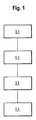
- Fig. 1 shows schematically the method steps of a method for producing pellets 10, as shown, for example, in FIG Figures 2 to 16c are shown.
- a first method step S1 a layer 12 or a stack of several stacked layers 12 of metal foam material 14 is provided, which is then comminuted in a second method step S2 into metal foam material pieces 18, which then in a third method step S3 into pellet-shaped metal foam blanks 16 be shaped.
- the metal foam blanks 16 are further processed into finished pellets 10.
- the pellets 10 obtained in this way have a high mechanical stability and can be, as follows described, use to produce a catalyst filling 20 of a reactor 22.
- a static mixer for example for an absorption or distillation column
- a static mixer also fulfills a catalyst function or, conversely, a catalyst filling 20 can act at the same time as a static mixer.
- pellet-shaped metal foam blanks 16 having a helical shape such as in the middle of FIG Fig. 7
- the pellet-shaped metal foam blanks 16 then become the pellet 10 made of metal foam 24.
- the bulges and indentations 38, 40 produced in these pellets 10 by folding can cause turbulence in a reactant flow and thus improve the heat transport properties of a corresponding catalyst bed compared to pellets 10 without indentations 38, 40.
- the centrally arranged passage reduces the pressure loss.
- the in Fig. 5 multilayer pellet 10 shown are seven indentations 40 and in the case of FIG Fig. 6
- the pellet 10 shown, twelve indentations 40 are formed, which were obtained by bending open individual layers 12 of metal foam material 14 and extend axially. These indentations 40 cause turbulence and thus improve the heat transport properties of a corresponding catalyst bed compared to a catalyst bed with pellets 10 without these indentations 40.
- the pellets 10 shown have a compact structure, so that with a random packing of a catalyst bed with such pellets 10, a high density can be achieved, which in turn is advantageous for the heat and mass transport properties and can cause a high degree of turbulence.
- the helical pellet 10 is very compact, which has an advantageous effect on the heat and mass transport properties.
- the mass transport properties such helical pellets 10 are improved due to the short transport routes.
- an axial passage is created in the inner region of the pellet 10, which passage can reduce the pressure loss of a corresponding catalyst bed.
- Random packing of a catalyst bed with helical pellets 10 leads to particularly strong turbulence.
- an ordered packing can also be realized.
- the helical pellets 10 can be stacked in order to create channels in the catalyst bed in a targeted manner in order to thereby design flow profiles in the catalyst bed.
- helical pellets 10 can also be produced.
- This in Fig. 8 The pellet 10 shown has been twisted into a spiral shape.
- a reactant stream 36 flowing along the pellet 10 can be set in rotation by the spiral shape of the pellet 10.
- the pellet 10 Due to the spiral shape, the pellet 10 has a relatively large amount of free volume, which reduces the pressure loss.
- targeted flow profiles can be generated. With a statistical packing, very turbulent flows can be achieved.
- pellets 10 with the in Figures 12 and 13 create the shapes shown.
- This in Fig. 12 The pellet 10 shown can be produced by winding a triangular metal foam material 14.
- the winding of a strip of metal foam material 14 can be used to produce a pellet 10 in the Fig. 13 almost rod-shaped shape shown, whereby by winding inside the in Fig. 13 Pellets shown an axial passage is created which is free of metal foam 24 and which reduces the pressure loss in a corresponding catalyst bed.
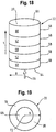
- the pellet 10 shown has the shape of an open hollow cylinder with an opening angle ⁇ of 180 ° and an axial opening 42 in a jacket wall 44. Other opening angles in the range from 1 ° to 359 ° are also possible. An opening angle ⁇ of 0 ° corresponds to a closed hollow cylinder.
- a pellet 10 in the form of an open hollow cylinder can be produced, for example, by rolling metal foam material 14.
- the opening 42 provided in the jacket wall 44 allows the reactant flow 36 to penetrate to the inner jacket surface 46 of the hollow cylindrical pellet 10.
- Pellet 10 shown guide the reactant stream 36 similar to a tube, whereby a very low pressure loss can be achieved.
- FIG Figures 16a, 16b and 16c Schematic cross-sections of pellets 10 with three or two different layers 12 are shown in FIG Figures 16a, 16b and 16c shown.
- the different layers 12 can be soldered with a soldering foil 30 or by pressing the layers 12 be connected to one another and have different pores 26.
- the pellet 10 of Figure 16a has in the middle layer 12 first pores 52 with larger diameters and second pores 54 with smaller diameters.
- the diameter of the first pores 52 can be in the range from 500 ⁇ m to 10,000 ⁇ m
- the diameter of the second pores 54 can be in the range from 10 ⁇ m to 3000 ⁇ m.
- Such a distribution of the pores 52, 54 can be used, for example, to influence the residence time of reactants in the pellet 10.
- the smaller pores 54 inside the in Figure 16b pellets shown increase the residence time of reactants.
- a pellet 10 made up of two different layers 12 Figure 16c
- Larger first pores 52 are provided in one layer 12 and smaller second pores 54 are provided in the other layer 12.
- the reactant stream 36 preferably enters and exits the pellet 10 from the side with the first pores 52.
- the residence time within the pellet 10 can be varied. Because smaller pores 54 are provided on one side of the pellet 10 than on the other side of the pellet, on the side with the smaller pores 54, part of the reactant flow 36 can be diverted when it hits the pellet 10, which in turn influences the fluid dynamics, whereby the heat and mass transport properties of a catalyst filling can be influenced.
- the pellet 10 shown has a closed outer surface 56. This means that no pores 20 lead into the interior of the pellet 10 on the closed outer surface 56, so that a reactant stream 36 flowing against the closed outer surface 56 cannot penetrate the pellet 10 and therefore ricochets off the outer surface 32. This can result in turbulence, so that the heat and material transport properties can also be influenced by partially or completely closing an outer surface 32 of a pellet 10.
- Pellet 10 shown, two opposite closed outer surfaces 56 are provided.
- a closed outer surface 56 can be produced, for example, by applying a soldering foil 30 to an outer surface 32 of a pellet 10 and then heating the soldering foil 30. It is also possible, in a metal foam material 14 with several layers 12, which are connected by means of soldering foils 30, to produce inner boundary surfaces in a pellet 10 which can be partially or completely closed. Partially or completely closed inner interfaces also influence a reactant flow 36 which has penetrated into the pellet. In this way, for example, the residence time of the reactants within the pellet 10 can be varied or turbulence can be generated in the reactant flow 36.
- a reactor 22 through which a reactant stream 36 flows is shown in a perspective view.
- a catalyst filling 20 is provided which comprises a multiplicity of pellets 10, namely pellets 10 which differ in terms of their size, shape, surface, density, porosity, orientation and / or their material, the individual pellets 10 in Figures 18 to 20 are not shown.
- the reactor 22 is divided in the axial direction L into a plurality of regions 58 which differ with regard to their catalyst filling 20.
- a first region 60 can contain a catalyst filling with pellets 10, which optimize the heat supply or removal properties of the reactor 20.
- the catalyst filling can comprise pellets 10, which are optimized, for example, with regard to the material transport properties, in order to convert the reactant flow 36 as completely as possible.
- the in Fig. 18 In the reactor shown in the figure, the first and second regions 60, 62 are arranged alternately along the axial direction L of the reactor 22 and thus form discrete layers with different compositions.
- the catalyst filling 20 changes gradually along the axial direction L of the reactor 22.
- a first type or mixture of pellets 10 is provided in the area of a Reactor inlet 64, in which the reactant stream 36 enters the reactor 22, a first type or mixture of pellets 10 is provided and a second type or mixture of pellets 10 is provided in a region of the reactor outlet 66.
- the first type or mixture of pellets 10 merges into the second type or mixture of pellets 10 along the axial direction L of the reactor.
- a different fluid dynamic environment can be provided at the reactor inlet 64 than at the reactor outlet 66.
- the distribution of different pellets 10 in the catalyst filling can take place in the radial direction R homogeneously, gradually or in discrete rings.
- FIG. 19 The cross-sectional view of a reactor shown in the figure shows that the catalyst filling 20 has a radially inner region 68 and a radially outer region 70.
- a different type or a different mixture of pellets 10 can be provided in the radially inner region 68 than in the radially outer region 70.
- the transition between the radially inner region 68 and the radially outer region 70 can take place abruptly so that the catalyst filling in discrete rings having radial direction R. Alternatively, there can also be a gradual transition between the inner area 68 and the outer area 70.
- Fig. 20 a partially transparent view of a reactor is shown, the catalyst filling 20 of which changes gradually in the axial direction L and abruptly in the radial direction R.
- the inner area 68 extends from the center point 72 of the reactor 22 to the reactor wall 74.
- the radius of the inner area 68 becomes continuously smaller, whereas the thickness of an outer area 70 increases so that the inner region 68 over the entire length of the reactor 22 has the shape of a cone.
- Table 1 lists five examples of pellets 10 according to the invention with cube or disk geometry, each made of a nickel-chromium-aluminum alloy (NiCrAl), and two comparative examples of ceramic pellets made of calcium aluminate.
- Figures 21a and 21b show the pressure drop properties for pellets 10 of Examples 1 to 5 and Comparative Examples 1 and 2.
- a measured pressure loss ⁇ p in bar is plotted against a set material flow rate m in kg / s.
- Figure 21a shows that there is an approximately linear relationship between the pressure loss ⁇ p and the set substance flow rate m.
- ⁇ m represents the difference between the highest and lowest set substance flow rates for an example or comparative example and ⁇ ( ⁇ p) the difference between the substance flow rates for these substance flows
- ⁇ ( ⁇ p) / ⁇ m indicate the gradients of straight lines which pass through the start and end points of the in Figure 21a
- the curves shown run and form a measure of the pressure loss per substance flow for the examples and comparative examples. The higher the value for ⁇ ( ⁇ p) / ⁇ m, the greater the pressure loss with increasing mass and material transport.
- the method according to the invention can produce pellets 10 with different effects on the pressure loss, i.e. the pellets 10 can be well adapted to the requirements of their planned area of application.
- a change in the pore diameter can be used in order to influence the pressure loss, as can be seen from Examples 1 and 2.
- the use of a pellet 10 with several layers 12 reduces the pressure loss and at the same time improves the material transport properties, as can be seen from Examples 3 and 4.
- both the pressure loss and the material transport can be optimized depending on the intended use of the pellets 10.
- the disk-shaped pellet 10 according to example 5 has the same good material transport properties as a pellet according to example 3, but with an increased pressure loss.
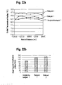
- Figure 22a shows three radial outlet temperature profiles.
- tubular reactors 22 with diameters of 3 inches (7.62 cm) after their packing with different pellets 10 with air preheated to 900 ° C as a fluid at a pressure of 5 bar and an empty pipe speed of 1 m / s, the Reactors 22 are each arranged in ovens heated to 1000 ° C.
- the temperature is measured at different radial positions. By plotting the measured outlet temperatures against the associated radial positions, the in Figure 22a outlet temperature profiles shown.
- Average heat transfer coefficients can be calculated from the outlet temperature profiles obtained, which in Figure 22b are shown. Links in Figure 22b the heat transfer coefficient of the reactor 22 packed with ceramic pellets is shown, which is significantly lower than the mean heat transfer coefficient which can be attributed to the pellets according to Examples 1 and 3. This shows that the pellets 10 according to the invention made of metal foam 24 can be used to optimize the heat transport of reactors.
Landscapes
- Chemical & Material Sciences (AREA)
- Organic Chemistry (AREA)
- Chemical Kinetics & Catalysis (AREA)
- Engineering & Computer Science (AREA)
- Materials Engineering (AREA)
- Physics & Mathematics (AREA)
- Thermal Sciences (AREA)
- Mechanical Engineering (AREA)
- Metallurgy (AREA)
- Manufacturing & Machinery (AREA)
- Catalysts (AREA)
- Nanotechnology (AREA)
Claims (14)
- Procédé de fabrication d'une pastille (10), destinée en particulier à un catalyseur et/ou à un mélangeur statique, comprenant les étapes:découper et/ou déformer au moins une couche (12) de matériau en mousse métallique (14) en une forme de pastille,caractérisé en ce quela pastille (10) présente un volume de 0,8 mm3 à 15 cm3, et la porosité de la pastille est supérieure ou égale à 70%, la porosité de la pastille étant déterminée par analyse d'image à partir d'une coupe métallographique de la pastille en prenant une image de la coupe métallographique et en mettant en relation les surfaces de l'image avec et sans matériau.
- Procédé la revendication 1,
caractérisé en ce que
le matériau en mousse métallique (14) est fritté. - Procédé selon la revendication 1 ou 2,
caractérisé en ce que
le matériau en mousse métallique (14) contient des pores (26) dont les diamètres sont répartis de manière monomodale ou multimodale, en particulier bimodale. - Procédé selon l'une au moins des revendications précédentes,
caractérisé en ce que
l'on fournit au moins deux couches (12) de matériaux en mousse métallique différents (14), qui sont en particulier reliées entre elles par pressage et/ou par brasage au moyen d'une feuille de brasage (30). - Procédé selon l'une au moins des revendications précédentes,
caractérisé en ce que
le matériau en mousse métallique (14) contient des pores (26) présentant un diamètre de 10 µm à 10 000 µm. - Pastille (10), susceptible d'être obtenue par un procédé selon l'une au moins des revendications 1 à 5,
comprenant au moins une couche (12) de mousse métallique (24). - Pastille (10) selon la revendication 6,
caractérisée par
au moins une échancrure (28) et/ou rainure (34) extérieure et/ou au moins un enroulement et/ou une torsion d'une couche (12) de mousse métallique (24). - Pastille (10) selon la revendication 6 ou 7,
caractérisée en ce que
au moins une surface extérieure (32) et/ou une interface intérieure de la pastille (10) est au moins partiellement fermée. - Pastille (10) selon l'une au moins des revendications 6 à 8,
caractérisée en ce que
la pastille (10) comprend au moins deux couches (12) de mousses métalliques différentes (24). - Pastille (10) selon l'une au moins des revendications 6 à 9,
caractérisée en ce que
la pastille (10) est constituée au moins sensiblement en mousse métallique (24). - Pastille (10) selon l'une au moins des revendications 6 à 10,
caractérisée en ce que
la mousse métallique (24) présente des pores (26) dont les diamètres sont répartis de manière monomodale ou multimodale, en particulier bimodale. - Pastille (10) selon l'une au moins des revendications 6 à 11,
caractérisée en ce que
la mousse métallique (24) présente des pores (26) d'un diamètre de 10 µm à 10 000 µm. - Garniture de catalyseur (20) comprenant une multitude de pastilles (10) selon l'une au moins des revendications 6 à 12.
- Mélangeur statique, par exemple pour une colonne d'absorption ou de distillation, comprenant une multitude de pastilles (10) selon l'une au moins des revendications 6 à 12.
Priority Applications (11)
| Application Number | Priority Date | Filing Date | Title |
|---|---|---|---|
| DK17154045.3T DK3354337T3 (da) | 2017-01-31 | 2017-01-31 | Fremgangsmåde til at fremstille en metalskumspellet, metalskumpellet, katalysatorfyld og statisk mixer |
| ES17154045T ES2875507T3 (es) | 2017-01-31 | 2017-01-31 | Procedimiento para producir una pastilla de espuma metálica, pastilla de espuma metálica, llenado de catalizador y mezclador estático |
| EP17154045.3A EP3354337B1 (fr) | 2017-01-31 | 2017-01-31 | Procédé de fabrication d'un granulé de mousse metallique, granulé de mousse metallique, remplissage de catalyseur et mélangeur statique |
| PCT/EP2018/052238 WO2018141729A1 (fr) | 2017-01-31 | 2018-01-30 | Procédé de production d'un grain, grain, charge de catalyseur et mélangeur statique |
| CN201880009383.5A CN110337327A (zh) | 2017-01-31 | 2018-01-30 | 生产颗粒的方法、颗粒、催化剂装料和静态混合器 |
| CA3051722A CA3051722C (fr) | 2017-01-31 | 2018-01-30 | Procede de production d'un grain, grain, charge de catalyseur et melangeur statique |
| US16/480,692 US11660582B2 (en) | 2017-01-31 | 2018-01-30 | Method for producing a pellet, pellet, catalyst charge, and static mixer |
| JP2019561360A JP7433049B2 (ja) | 2017-01-31 | 2018-01-30 | ペレットの作製方法ならびにペレット、触媒充填物およびスタティックミキサー |
| EP18703728.8A EP3562581A1 (fr) | 2017-01-31 | 2018-01-30 | Procédé de production d'un grain, grain, charge de catalyseur et mélangeur statique |
| KR1020197023346A KR102518921B1 (ko) | 2017-01-31 | 2018-01-30 | 펠릿 제조 방법, 펠릿, 촉매 충전물, 및 정적 혼합기 |
| RU2019125833A RU2747993C2 (ru) | 2017-01-31 | 2018-01-30 | Способ изготовления гранул, гранула, загрузка катализаторов |
Applications Claiming Priority (1)
| Application Number | Priority Date | Filing Date | Title |
|---|---|---|---|
| EP17154045.3A EP3354337B1 (fr) | 2017-01-31 | 2017-01-31 | Procédé de fabrication d'un granulé de mousse metallique, granulé de mousse metallique, remplissage de catalyseur et mélangeur statique |
Publications (2)
| Publication Number | Publication Date |
|---|---|
| EP3354337A1 EP3354337A1 (fr) | 2018-08-01 |
| EP3354337B1 true EP3354337B1 (fr) | 2021-04-14 |
Family
ID=58046477
Family Applications (2)
| Application Number | Title | Priority Date | Filing Date |
|---|---|---|---|
| EP17154045.3A Active EP3354337B1 (fr) | 2017-01-31 | 2017-01-31 | Procédé de fabrication d'un granulé de mousse metallique, granulé de mousse metallique, remplissage de catalyseur et mélangeur statique |
| EP18703728.8A Withdrawn EP3562581A1 (fr) | 2017-01-31 | 2018-01-30 | Procédé de production d'un grain, grain, charge de catalyseur et mélangeur statique |
Family Applications After (1)
| Application Number | Title | Priority Date | Filing Date |
|---|---|---|---|
| EP18703728.8A Withdrawn EP3562581A1 (fr) | 2017-01-31 | 2018-01-30 | Procédé de production d'un grain, grain, charge de catalyseur et mélangeur statique |
Country Status (10)
| Country | Link |
|---|---|
| US (1) | US11660582B2 (fr) |
| EP (2) | EP3354337B1 (fr) |
| JP (1) | JP7433049B2 (fr) |
| KR (1) | KR102518921B1 (fr) |
| CN (1) | CN110337327A (fr) |
| CA (1) | CA3051722C (fr) |
| DK (1) | DK3354337T3 (fr) |
| ES (1) | ES2875507T3 (fr) |
| RU (1) | RU2747993C2 (fr) |
| WO (1) | WO2018141729A1 (fr) |
Families Citing this family (4)
| Publication number | Priority date | Publication date | Assignee | Title |
|---|---|---|---|---|
| KR20210038540A (ko) * | 2019-09-25 | 2021-04-07 | 에보닉 오퍼레이션스 게엠베하 | 촉매 반응기 |
| EP4066142A1 (fr) * | 2019-11-26 | 2022-10-05 | Basf Se | Optimisation de géométrie de corps façonné et outils de fabrication |
| CN114102853A (zh) * | 2020-08-28 | 2022-03-01 | 中国科学院金属研究所 | 一种基于三维开孔泡沫陶瓷材料的静态混合装置及其应用 |
| US12064827B1 (en) * | 2021-06-13 | 2024-08-20 | Garvey Holding LLC | Methods, systems, and apparatus for joining metallic fabrics |
Family Cites Families (25)
| Publication number | Priority date | Publication date | Assignee | Title |
|---|---|---|---|---|
| SU533390A1 (ru) | 1974-08-08 | 1976-10-30 | Предприятие П/Я Р-6603 | Катализатор дл конверсии углеводородов |
| JPS62144750A (ja) * | 1985-12-20 | 1987-06-27 | Tanaka Kikinzoku Kogyo Kk | 白金族系酸化触媒の製法 |
| JPS6372738A (ja) * | 1986-09-17 | 1988-04-02 | Nippon Steel Chem Co Ltd | 発泡体の製造方法 |
| DE19533486A1 (de) * | 1995-09-12 | 1997-03-13 | Basf Ag | Monomodale und polymodale Katalysatorträger und Katalysatoren mit engen Porengrößenverteilungen und deren Herstellverfahren |
| JPH09202904A (ja) * | 1995-11-20 | 1997-08-05 | Mitsubishi Materials Corp | 多孔質焼結金属板の製造装置 |
| JP2000357519A (ja) * | 1999-06-15 | 2000-12-26 | Katayama Tokushu Kogyo Kk | 金属多孔体、該金属多孔体からなる電池用電極板、および該電極板を備えた電池 |
| RU2193948C2 (ru) | 1999-07-06 | 2002-12-10 | Лебедев Виктор Иванович | Способ получения пористого металла и изделий из него |
| DE10048219A1 (de) | 2000-02-10 | 2002-04-11 | Sued Chemie Ag | Katalysator für die Hydrierung von ungesättigten Kohlenwasserstoffen |
| WO2001062994A1 (fr) * | 2000-02-22 | 2001-08-30 | Qinetiq Limited | Procede de fabrication de ferro-titane et d'autres alliages metalliques par reduction electrolytique |
| RU2003125636A (ru) | 2001-01-16 | 2005-02-27 | Агс Тарон Инвестментс Инк. (Ca) Агс Тарон Инвестментс Инк. (Ca) | Способ получения металлической пены или металлокомпозитных объектов с улучшенными прочностными, термическими и звукопоглощающими совйствами |
| US7250151B2 (en) | 2002-08-15 | 2007-07-31 | Velocys | Methods of conducting simultaneous endothermic and exothermic reactions |
| KR20060123151A (ko) | 2003-10-15 | 2006-12-01 | 바스프 악티엔게젤샤프트 | 외부 마찰 표면이 둥근 촉매적 비활성 성형 보디를 갖는촉매성 벌크 재료 |
| JP4010416B2 (ja) | 2003-11-21 | 2007-11-21 | 一朗 阿部 | 流体の浄化装置 |
| DE102005010248B4 (de) * | 2005-02-28 | 2006-10-26 | Fraunhofer-Gesellschaft zur Förderung der angewandten Forschung e.V. | Verfahren zur Herstellung eines offenporigen Metallschaumkörpers, ein so hergestellter Metallschaumkörper sowie seine Verwendungen |
| EP2120698A2 (fr) | 2006-12-20 | 2009-11-25 | Philips Intellectual Property & Standards GmbH | Dispositif pour influencer et/ou détecter des particules magnétiques dans une région d'action et procédé de fabrication d'une bobine en forme de disque |
| DE102007008823A1 (de) * | 2007-02-22 | 2008-08-28 | Alantum Gmbh & Co. Kg | Katalysatorträgerkörper |
| JP5036625B2 (ja) * | 2008-05-21 | 2012-09-26 | 旭有機材工業株式会社 | スタティックミキサーエレメント並びにそれを用いたスタティックミキサー及びバルブ並びに流体混合装置 |
| JP2011031171A (ja) * | 2009-07-31 | 2011-02-17 | Hitachi-Ge Nuclear Energy Ltd | 触媒反応装置 |
| WO2011144417A1 (fr) * | 2010-05-20 | 2011-11-24 | Nv Bekaert Sa | Matériau 3d poreux comportant une face usinée |
| US8828219B2 (en) * | 2011-01-24 | 2014-09-09 | Saudi Arabian Oil Company | Hydrocracking process with feed/bottoms treatment |
| JP6047380B2 (ja) | 2012-03-26 | 2016-12-21 | 株式会社東芝 | 燃料電池用または電解用の貴金属触媒層、膜電極接合体および燃料電池または電解セル |
| EP2873521A4 (fr) * | 2012-07-24 | 2016-06-29 | Alantum | Procédé de fabrication d'un empilement de mousse métallique |
| ES2638091T3 (es) * | 2013-12-10 | 2017-10-18 | Alantum Europe Gmbh | Cuerpo de espuma metálica con tamaño de grano controlado en su superficie, proceso para su producción y su uso |
| DE102014011678A1 (de) | 2014-08-05 | 2016-02-11 | Bwf Tec Gmbh & Co. Kg | Filterkerzenelement mit Metallschaumverstärkung |
| KR101614139B1 (ko) | 2014-08-07 | 2016-04-20 | 주식회사 알란텀 | 금속폼 스택 및 이의 제조방법 |
-
2017
- 2017-01-31 EP EP17154045.3A patent/EP3354337B1/fr active Active
- 2017-01-31 ES ES17154045T patent/ES2875507T3/es active Active
- 2017-01-31 DK DK17154045.3T patent/DK3354337T3/da active
-
2018
- 2018-01-30 WO PCT/EP2018/052238 patent/WO2018141729A1/fr not_active Ceased
- 2018-01-30 RU RU2019125833A patent/RU2747993C2/ru active
- 2018-01-30 CA CA3051722A patent/CA3051722C/fr active Active
- 2018-01-30 US US16/480,692 patent/US11660582B2/en active Active
- 2018-01-30 EP EP18703728.8A patent/EP3562581A1/fr not_active Withdrawn
- 2018-01-30 JP JP2019561360A patent/JP7433049B2/ja active Active
- 2018-01-30 CN CN201880009383.5A patent/CN110337327A/zh active Pending
- 2018-01-30 KR KR1020197023346A patent/KR102518921B1/ko active Active
Non-Patent Citations (1)
| Title |
|---|
| None * |
Also Published As
| Publication number | Publication date |
|---|---|
| WO2018141729A1 (fr) | 2018-08-09 |
| JP7433049B2 (ja) | 2024-02-19 |
| CA3051722C (fr) | 2023-11-07 |
| CA3051722A1 (fr) | 2018-08-09 |
| EP3562581A1 (fr) | 2019-11-06 |
| RU2747993C2 (ru) | 2021-05-18 |
| US20190388867A1 (en) | 2019-12-26 |
| RU2019125833A3 (fr) | 2021-02-15 |
| RU2019125833A (ru) | 2021-02-15 |
| DK3354337T3 (da) | 2021-05-10 |
| KR20190114995A (ko) | 2019-10-10 |
| US11660582B2 (en) | 2023-05-30 |
| KR102518921B1 (ko) | 2023-04-06 |
| JP2020506053A (ja) | 2020-02-27 |
| CN110337327A (zh) | 2019-10-15 |
| ES2875507T3 (es) | 2021-11-10 |
| EP3354337A1 (fr) | 2018-08-01 |
Similar Documents
| Publication | Publication Date | Title |
|---|---|---|
| EP3354337B1 (fr) | Procédé de fabrication d'un granulé de mousse metallique, granulé de mousse metallique, remplissage de catalyseur et mélangeur statique | |
| EP0673473B1 (fr) | Convertisseur catalytique a deux ou plusieurs corps en nid-d'abeilles contenus dans une enveloppe tubulaire, et son procede de fabrication | |
| EP2794152B1 (fr) | Procédé de fabrication d'un composant compact et composant produit au moyen dudit procédé | |
| EP1874465B1 (fr) | Support de catalyseur et son utilisation pour le réformage à la vapeur des hydrocarbures | |
| EP3585509B1 (fr) | Échangeur de chaleur et réacteur | |
| EP3569311A1 (fr) | Matrice pourvue de pièces moulées métalliques destinée à l'extrusion de corps moulés | |
| EP1212163B1 (fr) | Procede de production d'un corps a nid d'abeilles fritte | |
| EP3802060B1 (fr) | Réacteur destiné à la mise en oeuvre d'une réaction d'équilibre chimique | |
| EP3018412A1 (fr) | Récupérateur et brûleur à récupération | |
| EP1027177B1 (fr) | Procede de fabrication de profiles creux en nickel-titane | |
| EP3297759B1 (fr) | Corps à plusieurs étages comportant une pluralité de canaux d'écoulement, préparation et utilisation | |
| DE102017213515B4 (de) | Wabenstruktur-Formwerkzeug | |
| DE3213413C2 (de) | Verwendung monolithischer Katalysatorträger | |
| EP2414066A1 (fr) | Dispositif de filtration et générateur de gaz comportant un dispositif de filtration | |
| DE3426240C2 (fr) | ||
| DE3726872C2 (fr) | ||
| EP0186130A2 (fr) | Procédé pour la fabrication d'éléments annulaires pour des structures cylindriques des tuyaux collecteurs d'échangeurs thermiques | |
| DE202009004082U1 (de) | Wabenkörper mit Metallschaum | |
| DE2743703C2 (fr) | ||
| DE102014105770A1 (de) | Verfahren zur Beeinflussung einer Fluidströmung | |
| WO2025002990A1 (fr) | Unité de membrane structurée, procédé de production et procédé de préparation | |
| DE102019113587A1 (de) | Verfahren und Vorrichtung zum Herstellen eines wabenförmigen, keramischen Körpers eines Katalysators oder Partikelfilters | |
| DE102009023969A1 (de) | Verfahren zum Herstellen eines Regenerators, insbesondere für eine Stirling-Kühleinrichtung, und Regenerator | |
| DE2052793A1 (de) | Turbinenschaufel | |
| CH463551A (de) | Teilweise poröser Bauteil und Verfahren zu seiner Herstellung |
Legal Events
| Date | Code | Title | Description |
|---|---|---|---|
| PUAI | Public reference made under article 153(3) epc to a published international application that has entered the european phase |
Free format text: ORIGINAL CODE: 0009012 |
|
| STAA | Information on the status of an ep patent application or granted ep patent |
Free format text: STATUS: THE APPLICATION HAS BEEN PUBLISHED |
|
| AK | Designated contracting states |
Kind code of ref document: A1 Designated state(s): AL AT BE BG CH CY CZ DE DK EE ES FI FR GB GR HR HU IE IS IT LI LT LU LV MC MK MT NL NO PL PT RO RS SE SI SK SM TR |
|
| AX | Request for extension of the european patent |
Extension state: BA ME |
|
| STAA | Information on the status of an ep patent application or granted ep patent |
Free format text: STATUS: REQUEST FOR EXAMINATION WAS MADE |
|
| 17P | Request for examination filed |
Effective date: 20190118 |
|
| RBV | Designated contracting states (corrected) |
Designated state(s): AL AT BE BG CH CY CZ DE DK EE ES FI FR GB GR HR HU IE IS IT LI LT LU LV MC MK MT NL NO PL PT RO RS SE SI SK SM TR |
|
| STAA | Information on the status of an ep patent application or granted ep patent |
Free format text: STATUS: EXAMINATION IS IN PROGRESS |
|
| 17Q | First examination report despatched |
Effective date: 20200416 |
|
| GRAP | Despatch of communication of intention to grant a patent |
Free format text: ORIGINAL CODE: EPIDOSNIGR1 |
|
| STAA | Information on the status of an ep patent application or granted ep patent |
Free format text: STATUS: GRANT OF PATENT IS INTENDED |
|
| INTG | Intention to grant announced |
Effective date: 20201218 |
|
| GRAS | Grant fee paid |
Free format text: ORIGINAL CODE: EPIDOSNIGR3 |
|
| GRAA | (expected) grant |
Free format text: ORIGINAL CODE: 0009210 |
|
| STAA | Information on the status of an ep patent application or granted ep patent |
Free format text: STATUS: THE PATENT HAS BEEN GRANTED |
|
| AK | Designated contracting states |
Kind code of ref document: B1 Designated state(s): AL AT BE BG CH CY CZ DE DK EE ES FI FR GB GR HR HU IE IS IT LI LT LU LV MC MK MT NL NO PL PT RO RS SE SI SK SM TR |
|
| REG | Reference to a national code |
Ref country code: GB Ref legal event code: FG4D Free format text: NOT ENGLISH |
|
| REG | Reference to a national code |
Ref country code: CH Ref legal event code: EP |
|
| REG | Reference to a national code |
Ref country code: DE Ref legal event code: R096 Ref document number: 502017010048 Country of ref document: DE |
|
| REG | Reference to a national code |
Ref country code: DK Ref legal event code: T3 Effective date: 20210504 |
|
| REG | Reference to a national code |
Ref country code: IE Ref legal event code: FG4D Free format text: LANGUAGE OF EP DOCUMENT: GERMAN |
|
| REG | Reference to a national code |
Ref country code: AT Ref legal event code: REF Ref document number: 1381822 Country of ref document: AT Kind code of ref document: T Effective date: 20210515 |
|
| REG | Reference to a national code |
Ref country code: SE Ref legal event code: TRGR |
|
| REG | Reference to a national code |
Ref country code: NO Ref legal event code: T2 Effective date: 20210414 |
|
| REG | Reference to a national code |
Ref country code: NL Ref legal event code: FP |
|
| REG | Reference to a national code |
Ref country code: LT Ref legal event code: MG9D |
|
| PG25 | Lapsed in a contracting state [announced via postgrant information from national office to epo] |
Ref country code: HR Free format text: LAPSE BECAUSE OF FAILURE TO SUBMIT A TRANSLATION OF THE DESCRIPTION OR TO PAY THE FEE WITHIN THE PRESCRIBED TIME-LIMIT Effective date: 20210414 Ref country code: BG Free format text: LAPSE BECAUSE OF FAILURE TO SUBMIT A TRANSLATION OF THE DESCRIPTION OR TO PAY THE FEE WITHIN THE PRESCRIBED TIME-LIMIT Effective date: 20210714 Ref country code: FI Free format text: LAPSE BECAUSE OF FAILURE TO SUBMIT A TRANSLATION OF THE DESCRIPTION OR TO PAY THE FEE WITHIN THE PRESCRIBED TIME-LIMIT Effective date: 20210414 Ref country code: LT Free format text: LAPSE BECAUSE OF FAILURE TO SUBMIT A TRANSLATION OF THE DESCRIPTION OR TO PAY THE FEE WITHIN THE PRESCRIBED TIME-LIMIT Effective date: 20210414 |
|
| REG | Reference to a national code |
Ref country code: ES Ref legal event code: FG2A Ref document number: 2875507 Country of ref document: ES Kind code of ref document: T3 Effective date: 20211110 |
|
| PG25 | Lapsed in a contracting state [announced via postgrant information from national office to epo] |
Ref country code: PL Free format text: LAPSE BECAUSE OF FAILURE TO SUBMIT A TRANSLATION OF THE DESCRIPTION OR TO PAY THE FEE WITHIN THE PRESCRIBED TIME-LIMIT Effective date: 20210414 Ref country code: PT Free format text: LAPSE BECAUSE OF FAILURE TO SUBMIT A TRANSLATION OF THE DESCRIPTION OR TO PAY THE FEE WITHIN THE PRESCRIBED TIME-LIMIT Effective date: 20210816 Ref country code: RS Free format text: LAPSE BECAUSE OF FAILURE TO SUBMIT A TRANSLATION OF THE DESCRIPTION OR TO PAY THE FEE WITHIN THE PRESCRIBED TIME-LIMIT Effective date: 20210414 Ref country code: LV Free format text: LAPSE BECAUSE OF FAILURE TO SUBMIT A TRANSLATION OF THE DESCRIPTION OR TO PAY THE FEE WITHIN THE PRESCRIBED TIME-LIMIT Effective date: 20210414 Ref country code: GR Free format text: LAPSE BECAUSE OF FAILURE TO SUBMIT A TRANSLATION OF THE DESCRIPTION OR TO PAY THE FEE WITHIN THE PRESCRIBED TIME-LIMIT Effective date: 20210715 Ref country code: IS Free format text: LAPSE BECAUSE OF FAILURE TO SUBMIT A TRANSLATION OF THE DESCRIPTION OR TO PAY THE FEE WITHIN THE PRESCRIBED TIME-LIMIT Effective date: 20210814 |
|
| REG | Reference to a national code |
Ref country code: DE Ref legal event code: R097 Ref document number: 502017010048 Country of ref document: DE |
|
| PG25 | Lapsed in a contracting state [announced via postgrant information from national office to epo] |
Ref country code: RO Free format text: LAPSE BECAUSE OF FAILURE TO SUBMIT A TRANSLATION OF THE DESCRIPTION OR TO PAY THE FEE WITHIN THE PRESCRIBED TIME-LIMIT Effective date: 20210414 Ref country code: EE Free format text: LAPSE BECAUSE OF FAILURE TO SUBMIT A TRANSLATION OF THE DESCRIPTION OR TO PAY THE FEE WITHIN THE PRESCRIBED TIME-LIMIT Effective date: 20210414 Ref country code: CZ Free format text: LAPSE BECAUSE OF FAILURE TO SUBMIT A TRANSLATION OF THE DESCRIPTION OR TO PAY THE FEE WITHIN THE PRESCRIBED TIME-LIMIT Effective date: 20210414 Ref country code: SM Free format text: LAPSE BECAUSE OF FAILURE TO SUBMIT A TRANSLATION OF THE DESCRIPTION OR TO PAY THE FEE WITHIN THE PRESCRIBED TIME-LIMIT Effective date: 20210414 Ref country code: SK Free format text: LAPSE BECAUSE OF FAILURE TO SUBMIT A TRANSLATION OF THE DESCRIPTION OR TO PAY THE FEE WITHIN THE PRESCRIBED TIME-LIMIT Effective date: 20210414 |
|
| PLBE | No opposition filed within time limit |
Free format text: ORIGINAL CODE: 0009261 |
|
| STAA | Information on the status of an ep patent application or granted ep patent |
Free format text: STATUS: NO OPPOSITION FILED WITHIN TIME LIMIT |
|
| 26N | No opposition filed |
Effective date: 20220117 |
|
| PG25 | Lapsed in a contracting state [announced via postgrant information from national office to epo] |
Ref country code: IS Free format text: LAPSE BECAUSE OF FAILURE TO SUBMIT A TRANSLATION OF THE DESCRIPTION OR TO PAY THE FEE WITHIN THE PRESCRIBED TIME-LIMIT Effective date: 20210814 Ref country code: AL Free format text: LAPSE BECAUSE OF FAILURE TO SUBMIT A TRANSLATION OF THE DESCRIPTION OR TO PAY THE FEE WITHIN THE PRESCRIBED TIME-LIMIT Effective date: 20210414 |
|
| PG25 | Lapsed in a contracting state [announced via postgrant information from national office to epo] |
Ref country code: MC Free format text: LAPSE BECAUSE OF FAILURE TO SUBMIT A TRANSLATION OF THE DESCRIPTION OR TO PAY THE FEE WITHIN THE PRESCRIBED TIME-LIMIT Effective date: 20210414 |
|
| REG | Reference to a national code |
Ref country code: CH Ref legal event code: PL |
|
| PG25 | Lapsed in a contracting state [announced via postgrant information from national office to epo] |
Ref country code: LU Free format text: LAPSE BECAUSE OF NON-PAYMENT OF DUE FEES Effective date: 20220131 |
|
| PG25 | Lapsed in a contracting state [announced via postgrant information from national office to epo] |
Ref country code: LI Free format text: LAPSE BECAUSE OF NON-PAYMENT OF DUE FEES Effective date: 20220131 Ref country code: CH Free format text: LAPSE BECAUSE OF NON-PAYMENT OF DUE FEES Effective date: 20220131 |
|
| PG25 | Lapsed in a contracting state [announced via postgrant information from national office to epo] |
Ref country code: IE Free format text: LAPSE BECAUSE OF NON-PAYMENT OF DUE FEES Effective date: 20220131 |
|
| P01 | Opt-out of the competence of the unified patent court (upc) registered |
Effective date: 20230601 |
|
| PG25 | Lapsed in a contracting state [announced via postgrant information from national office to epo] |
Ref country code: HU Free format text: LAPSE BECAUSE OF FAILURE TO SUBMIT A TRANSLATION OF THE DESCRIPTION OR TO PAY THE FEE WITHIN THE PRESCRIBED TIME-LIMIT; INVALID AB INITIO Effective date: 20170131 |
|
| PG25 | Lapsed in a contracting state [announced via postgrant information from national office to epo] |
Ref country code: MK Free format text: LAPSE BECAUSE OF FAILURE TO SUBMIT A TRANSLATION OF THE DESCRIPTION OR TO PAY THE FEE WITHIN THE PRESCRIBED TIME-LIMIT Effective date: 20210414 Ref country code: CY Free format text: LAPSE BECAUSE OF FAILURE TO SUBMIT A TRANSLATION OF THE DESCRIPTION OR TO PAY THE FEE WITHIN THE PRESCRIBED TIME-LIMIT Effective date: 20210414 |
|
| PG25 | Lapsed in a contracting state [announced via postgrant information from national office to epo] |
Ref country code: MT Free format text: LAPSE BECAUSE OF FAILURE TO SUBMIT A TRANSLATION OF THE DESCRIPTION OR TO PAY THE FEE WITHIN THE PRESCRIBED TIME-LIMIT Effective date: 20210414 |
|
| PG25 | Lapsed in a contracting state [announced via postgrant information from national office to epo] |
Ref country code: TR Free format text: LAPSE BECAUSE OF FAILURE TO SUBMIT A TRANSLATION OF THE DESCRIPTION OR TO PAY THE FEE WITHIN THE PRESCRIBED TIME-LIMIT Effective date: 20210414 |
|
| PGFP | Annual fee paid to national office [announced via postgrant information from national office to epo] |
Ref country code: NL Payment date: 20260121 Year of fee payment: 10 |
|
| PGFP | Annual fee paid to national office [announced via postgrant information from national office to epo] |
Ref country code: SE Payment date: 20260121 Year of fee payment: 10 |
|
| PGFP | Annual fee paid to national office [announced via postgrant information from national office to epo] |
Ref country code: GB Payment date: 20260123 Year of fee payment: 10 |
|
| PGFP | Annual fee paid to national office [announced via postgrant information from national office to epo] |
Ref country code: ES Payment date: 20260227 Year of fee payment: 10 |
|
| PGFP | Annual fee paid to national office [announced via postgrant information from national office to epo] |
Ref country code: DE Payment date: 20260328 Year of fee payment: 10 Ref country code: NO Payment date: 20260123 Year of fee payment: 10 Ref country code: DK Payment date: 20260126 Year of fee payment: 10 |
|
| PGFP | Annual fee paid to national office [announced via postgrant information from national office to epo] |
Ref country code: AT Payment date: 20260122 Year of fee payment: 10 |
|
| PGFP | Annual fee paid to national office [announced via postgrant information from national office to epo] |
Ref country code: IT Payment date: 20260126 Year of fee payment: 10 Ref country code: BE Payment date: 20260121 Year of fee payment: 10 |
|
| PGFP | Annual fee paid to national office [announced via postgrant information from national office to epo] |
Ref country code: FR Payment date: 20260123 Year of fee payment: 10 |