EP3354373A1 - Semi-solid die-casting machine and method - Google Patents
Semi-solid die-casting machine and method Download PDFInfo
- Publication number
- EP3354373A1 EP3354373A1 EP18153765.5A EP18153765A EP3354373A1 EP 3354373 A1 EP3354373 A1 EP 3354373A1 EP 18153765 A EP18153765 A EP 18153765A EP 3354373 A1 EP3354373 A1 EP 3354373A1
- Authority
- EP
- European Patent Office
- Prior art keywords
- semi
- filter
- molten metal
- solid state
- solid
- Prior art date
- Legal status (The legal status is an assumption and is not a legal conclusion. Google has not performed a legal analysis and makes no representation as to the accuracy of the status listed.)
- Withdrawn
Links
Images




Classifications
-
- B—PERFORMING OPERATIONS; TRANSPORTING
- B22—CASTING; POWDER METALLURGY
- B22D—CASTING OF METALS; CASTING OF OTHER SUBSTANCES BY THE SAME PROCESSES OR DEVICES
- B22D17/00—Pressure die casting or injection die casting, i.e. casting in which the metal is forced into a mould under high pressure
- B22D17/007—Semi-solid pressure die casting
-
- B—PERFORMING OPERATIONS; TRANSPORTING
- B22—CASTING; POWDER METALLURGY
- B22C—FOUNDRY MOULDING
- B22C9/00—Moulds or cores; Moulding processes
- B22C9/08—Features with respect to supply of molten metal, e.g. ingates, circular gates, skim gates
- B22C9/086—Filters
-
- B—PERFORMING OPERATIONS; TRANSPORTING
- B22—CASTING; POWDER METALLURGY
- B22D—CASTING OF METALS; CASTING OF OTHER SUBSTANCES BY THE SAME PROCESSES OR DEVICES
- B22D17/00—Pressure die casting or injection die casting, i.e. casting in which the metal is forced into a mould under high pressure
- B22D17/08—Cold chamber machines, i.e. with unheated press chamber into which molten metal is ladled
- B22D17/10—Cold chamber machines, i.e. with unheated press chamber into which molten metal is ladled with horizontal press motion
-
- B—PERFORMING OPERATIONS; TRANSPORTING
- B22—CASTING; POWDER METALLURGY
- B22D—CASTING OF METALS; CASTING OF OTHER SUBSTANCES BY THE SAME PROCESSES OR DEVICES
- B22D17/00—Pressure die casting or injection die casting, i.e. casting in which the metal is forced into a mould under high pressure
- B22D17/20—Accessories: Details
- B22D17/2015—Means for forcing the molten metal into the die
- B22D17/2023—Nozzles or shot sleeves
Definitions
- the present invention relates to a semi-solid die-casting machine and method.
- Some die-casting processes are essentially based on the immediate use of thixotropic material ("slurry on demand").
- these processes are essentially based on the idea of performing a rapid cooling of the metal bath to promote the increase of solidification nuclei and to simultaneously perform adequate mixing to apply however only in the first stages of solidification to promote dendritic multiplication in the phases where the dendrites are extremely thin and unstable given the high ratio between surface and volume and, above all, the thermal homogenisation of the semi-solid load in formation.
- This technique is generally capable of generating metallic material with a globular microstructure and allows its immediate use in known semi-solid forming processes.
- the purpose of the present invention is to provide a semi-solid die-casting machine and method that is easy and economical to make.
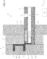
- reference numeral 1 globally denotes a semi-solid die-casting machine.
- the semi-solid die-casting machine 1 comprises a die casting mould 2, inside which a moulding chamber 3 is made.
- the semi-solid die-casting machine 1 further comprises an injection container 8 in which a chamber 9 is made suitable to contain the molten metal 25, a feeding channel 13 of the jet suitable to place the injection container 8 in communication with the moulding chamber 3, and an injection die 6 suitable to inject under pressure the molten metal 25, in the semi-solid state, contained in the injection container 8 into said moulding chamber 3 through said feeding channel 13.
- the moulding chamber 3 reproduces the negative of the shape of the piece to be made and is intended to receive the jet of molten metal in the semi-solid state for the subsequent completion of the solidification of said jet.
- the die-casting mould 2 may preferably be composed of a mobile die 4 and a fixed die 5.
- the mobile and fixed dies 4, 5 can be mechanically coupled to form/constitute the moulding chamber 3.
- the mobile die 4 can preferably be distanced, in a known manner, from the fixed die 5 to allow the piece to be extracted from the die-casting mould 2.
- the die-casting mould 2 can be supported by the injection press 6.
- the injection press 6 can be structured to feed under pressure the jet of molten metal in the semi-solid state inside the moulding chamber 3 through the feeding channel 13.
- the injection press 6 may include for example a support surface 7, to which a die of the mould 2 can be mechanically coupled/attached, preferably the fixed die 5.
- a support surface 7 to which a die of the mould 2 can be mechanically coupled/attached, preferably the fixed die 5.
- the press 6 shown schematically in Figure 1 is of the horizontal type and the support surface 7 is vertical, it is understood that the present invention may provide, alternatively, for the use of a vertical press 6 with a horizontal support surface 7.
- the injection press 6 may comprise a preferably cylindrical tubular injection container 8.
- the container 8 can be placed preferably through a corresponding cavity made in the support surface 7 and preferably, but not necessarily, through a corresponding cavity made through the fixed die 5 of the die-casting mould 2.
- a preferably cylindrical preparation chamber 9 may be made into which the molten metal is poured in the liquid state before injecting the molten metal in the semi-solid state into the moulding chamber 3 through the feeding channel 13.
- the preparation chamber 9 may be bounded by an injection piston 10 which is axially mounted along said preparation chamber 9 so as to vary the internal volume thereof.
- the feeding channel 13 of the jet is made in the mould 2 so as to place in fluidic communication the preparation chamber 9 with the moulding chamber 3.
- the feeding channel 13 of the jet is made in the mould 2 so as to present an inlet communicating with the preparation chamber 9 on the opposite side to the injection piston 10 and an outlet communicating with the moulding chamber 3.
- the feeding channel 13 may be made in the fixed die 5 of the mould 2 and may be communicating with the inlet mouth of the moulding chamber 3.
- the injection container 8 also has a feed opening 12, which is made through a wall, preferably upper, of the injection container 8 and in use is used to feed the molten metal in the liquid state into the preparation chamber 9.
- the die-casting machine 1 is also provided with at least one filter 11, which is arranged stably (rigidly) in the feeding channel 13 of the jet, and is structured in such a way as to: receive in input molten metal in the semi-solid state, causing a swirling mixing of the molten metal in the semi-solid state during the passage through the filter 11 of the molten metal in the semi-solid state, and to provide in output the molten metal in the mixed semi-solid state.
- the Applicant has found that the swirling mixing imparted by the filter 11 on the molten metal in the semi-solid state crossing the channel 13 determines the technical effect of advantageously producing a mechanical fluid stirring which in turn causes the formation of the thixotropic globular microstructure.
- the filter 11 is also structured so that the flow of molten metal in the semi-solid state in output from the filter 11 is itself an approximately laminar flow.
- the Applicant has found that the use of a filter capable of generating a laminar flow of metal in the semi-solid state conveniently makes it possible to reduce the formation of turbulence in the metal fed to the chamber 3, which would tend to incorporate oxides, causing deleterious effects on the integrity and the mechanical characteristics of the piece.
- the filter 11 is also structured in such a way as to filter, i.e. retain, during the crossing of the molten metal in the semi-solid state, impurities of predetermined dimensions contained in the metal itself.
- the Applicant has found that the placement of the filter 11 in the feeding channel 13 advantageously makes it possible to retain the oxides, films, inclusions and other impurities, which contribute to prejudicing the metal hygiene of the metal forming the piece 21.
- the filter 11 is also internally structured so as to determine on the flow of metal in the semi-solid state passing through it a refining of the metal beads.
- the filter 11 may consist of a thin perforated plate-shaped element, such as a net/mesh or perforated sheet, which is permanently placed inside the feeding channel 13 on a lying plane approximately transverse to the injection/forward direction of the metal in a semi-solid state into the channel 13 itself towards the chamber 3.
- a thin perforated plate-shaped element such as a net/mesh or perforated sheet
- the plate-shaped element or net/mesh is structured in such a way as to: receive in input the molten metal in the semi-solid state, causing a swirling mixing of the molten metal in the semi-solid state during the passage through the filter 11 of the molten metal in a semi-solid state, and to supply in output the molten metal in the mixed semi-solid state.
- the plate-shaped element or net/mesh can be made in a metal alloy characterized by a melting temperature of higher than about 650°C.
- the metal alloy of the perforated sheet or of the net/mesh forming the filter 11 may be aluminium and/or iron-based.
- the holes or openings through the filter 11 may have a diameter greater than about 1 mm and a density greater than or equal to about 50% of the area.
- the perforated sheet and the net/mesh may have a thickness determined along a direction orthogonal to said lying plane greater than or equal to about 1 mm.
- a filter 11 made of a perforated plate-shaped element or net/mesh in metal (metal grating flat filter”) ( Figure 7 ) in metal material, preferably an aluminium alloy, is particularly convenient since following the solidification of the metal in the chamber 3, the filter 11 remains completely embedded in the solidified biscuit of the piece 21, and can therefore be easily and fully recovered in a subsequent phase of recasting the biscuit, thereby reducing waste.
- This type of filter 11, in addition to being economical, is particularly effective in filtering the inclusions contained in the metal, exploiting the opportunity to superpose various ones until the result is achieved.
- the Applicant has also found it particularly convenient to use a second type of filter 11 called "cloth flat filter".
- This second type of filter 11 differs from that described above in that the filter 11 is composed of/made from fabrics in refractory material, suitably perforated.
- the refractory fabric of the filter 11 is structured in such a way as to: receive in input the molten metal in the semi-solid state, causing a swirling mixing of the molten metal in the semi-solid state during the passage through the filter 11 of the molten metal in a semi-solid state, and to supply in output the molten metal in the mixed semi-solid state.
- the refractory fabric of the filter 11 may be impregnated with one or more low-thermal capacity resins in such a way as to adequately increase the filtering efficiency.
- the low thermal capacity impregnating resins may include for example phenolic resins or similar resins.
- Figure 6 schematically shows a possible example of filter 11 belonging to the second type.
- the filters 11 belonging to the second type are conveniently suitable to be installed in the feeding channel 13 in a cascade configuration, in which a plurality of filters 11 are placed one after the other in the feeding channel 13 at a given distance from each other, to perform, on the one hand, the consecutive multiple filtering of the impurities present in the metal and on the other to facilitate the separation of the filling elements (biscuits) from the piece 21 obtained.
- This configuration makes it possible to conveniently simplify the separation of the casting branch from the piece.
- the Applicant has also found it particularly convenient to use a third type of filter 11 in which the filters 11 are volumetric ("volume filters").
- the volume filters are structured in such a way as to: receive in input the molten metal in the semi-solid state, causing a swirling mixing of the molten metal in the semi-solid state during the passage through the filter 11 of the molten metal in a semi-solid state, and to supply in output the molten metal in the mixed semi-solid state.
- These filters 11 are each provided with a body in ceramic material on which through holes are made defining inner channels suitable to be crossed in use by molten metal in the semi-solid state.
- a first category of volume filters that can be installed in the machine 1 may correspond to strainer core filters 11 ( Figure 8 ).
- the strainer core filter 11 is provided with a filtering body formed of a monolithic body, i.e. a monobloc, preferably of a parallelepiped or cylindrical or any other similar shape sized to be placed in the channel 13.
- the filter 11 is shaped so as to present the same cross-section as the channel 13 so that it can be housed internally.
- the through holes of the first strainer core category of volume filter 11 can be made in the monobloc of the filter 11 so as to form filtering channels adjacent to each other.
- the channels can be made in the monobloc so that the surface arrangement of the holes is substantially of the reticular or matrix type, i.e. in rows and columns. Each hole can be aligned or offset from adjacent holes.
- the through channels can also be made in the monobloc of the strainer core volume filter 11 so as to be substantially rectilinear, approximately parallel to each other.
- the through holes of the strainer core volume filter 11 can also be made in the monobloc of the filter 11 itself so as to be facing the channel 13 and each have a preferably approximately circular, elliptical or similar cross-section.
- the through holes of the strainer core volume filter 11 can also be made in the monobloc so as to have a diameter between about 4 and about 10 mm, and a depth along the relative axis between about 6 and about 20 mm.
- the strainer core volume filter 11 may conveniently be placed in the channel 13 at the inlet mouth of the chamber 3.
- a plurality of strainer core volume filters 11 may be stably arranged in cascade, suitably spaced apart from each other.
- each filter 11 may have holes with a smaller diameter than the diameter of the holes of another filter 11 placed immediately upstream and greater than the diameter of the holes of another filter 11 placed immediately downstream of said filter 11 along the crossing direction of the channel 13 by the jet of metal.
- strainer core volume filter 11 is particularly advantageous as it is economical, allows efficient filtering of impurities and has a high mechanical strength. It should be clarified that the strainer core volume filters 11 in addition to being able to retain impurities having a significant thickness (coarse impurities), are conveniently structured to (accelerate) improve the filling of the chamber 3 by making the flow of metal in the semi-solid state more laminar, and simultaneously preventing the formation of vortices in the space of the channel 13 between the outlet of said filter 11 and the chamber 3 so as to conveniently reduce the turbulence of the jet of metal injected into the mould 2.
- a second category of volume filters that can be installed in the machine 1 may correspond to pressed volume filters 11 ( Figure 9 ).
- the pressed volume filters 11 differ from the strainer core volume filter in that they are made using semi-dry ceramic mixtures pressed into moulds, at elevated pressures. Subsequently the pressed filter is placed in the oven and subjected to a cooking process, which, together with the mixture, determines the characteristics of thermal and mechanical resistance. The flow is determined by the size of the holes and by the density.
- the diameter of the channels/through holes of the pressed volume filter 11 can be between about 1 mm and about 3 mm.
- the thickness of the pressed volume filter 11 determined along the crossing direction of the filter 11 by the metal can conveniently be between about 10 mm and about 22 mm.
- the filtering area of the surface of the pressed volume filter 11 which in use is affected by the flow/jet of molten metal in the semi-solid state can be between about 45% and about 58% of the total surface area of the pressed volume filter 11, which in use comes into contact with the metal.
- the type of pressed semi-dry ceramic mixtures used for the filter 11 depends on the type of alloy/metal that passes through it. For example, semi-dry ceramic mixtures are used for aluminium, bronze, brass, and steels, based on the mixtures and the cooking.
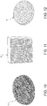
- a third category of volume filters that can be installed in the machine 1 may correspond to extruded volume filters 11 (an example of which is shown in Figure 11 .)
- the extruded volume filters 11 are structured in such a way as to: receive in input the molten metal in the semi-solid state, causing a swirling mixing of the molten metal in the semi-solid state during the passage through the filter 11 of the molten metal in a semi-solid state, and to supply in output the molten metal in the mixed semi-solid state.
- the extruded volume filters 11 have a structure substantially similar to that of the strainer core volume filters described above and differ from the latter in that they are produced using an extrusion process of ceramic materials with plastic behaviour using a mould.
- the extruded volume filters 11 have through channels/holes having an approximately rectangular cross-section.
- the Applicant has found that the use of the extruded volume filters 11 makes it possible to increase the filtering area and thus obtain a greater flow rate of the metal flowing through the cross-section, compared to the strainer core filters.
- the Applicant has found that the square or rectangular shape allows a higher flow of aluminium.
- the filtering area of the surface of the extruded volume filter 11, which in use is affected by the flow/jet of molten metal in the semi-solid state is about 65% of the total area of the filter surface 11 that comes into contact with the metal, for a lower thermal capacity. It should be specified that a greater density of the holes entails fewer thermal effects.
- the Applicant has also found that the square cross-section of the holes/channels increases the filtering capacity compared to holes with a circular cross-section.
- the ceramic foam filters 11 are structured in such a way as to: receive in input the molten metal in the semi-solid state, causing a swirling mixing of the molten metal in the semi-solid state during the passage through the filter 11 of the molten metal in a semi-solid state, and to supply in output the molten metal in the mixed semi-solid state.
- the ceramic foam filters 11 are made of ceramic material and comprise a substantially cellular structure formed of open cells. The cells are connected to each other so as to form in the filter body 11 a plurality of paths/channels through the filter.
- the paths/channels can be made in the filter 11 so that in use the flow of metal passing through the filter is diverted a series of times within the filter itself so that, on the one hand, swirling motions are generated inside the filter (random), and on the other the impurities are retained therein.
- the ceramic foam filter 11 is particularly convenient for performing deep filtrations i.e. particularly effective, since in use the flow of metal crossing the filter is subject to localized turbulence and sudden changes of direction that encourage the entrapment of metal impurities in the filter 11 itself. It is also appropriate to specify that the dimensions of the trapped inclusions are significantly lower than the internal size of the cells. In other words, in the loops of the path of semi-solid aluminium inside the filter 11, small impurities are deposited. In this regard, the Applicant has found that, in use, the trapped particles accumulate in the channels, forming therein bridges/obstructions that result in a progressive reduction in the flow rate of the filter.
- the filter must be sized according to the volume of metal that must pass through it, to the impurities that must be filtered before the filter itself is occluded.
- the flow rate of the metal flowing through the filter 11 depends on several variables, such as the amount of inclusions present in the metal alloy, the internal dimension of the holes/channels of the filter 11, the cohesion force existing between the particles of individual impurities or that present in the filter walls, which in turn depends on the material of the filter 11 itself.
- a thickness of the ceramic foam filter 11 transverse to the lying plane of the filter 11, particularly conveniently is between about 12 mm and about 50 mm.
- ceramic foam filters 11 is particularly advantageous since on the one hand it makes for high efficiency in the depth of metal filtration, and on the other is available in multiple shapes and sizes. Laboratory tests have shown that by varying the size and/or the shape of the ceramic foam filter 11 it is possible to achieve high mechanical strength, low apparent density, high melting temperature, high filtering efficiency, and high casting capacity.
- volumetric filters formed of a series of overlapping metal meshes ( Figure 10 ) or metal wire pad.
- the machine 1 may further comprise a cooling system to cool down the molten metal contained in the preparation chamber 9.
- the cooling system comprises a cooling device 19, which is placed near the preparation chamber 9 and is suitable to cool the molten metal in the liquid state contained in the preparation chamber 9 to ensure that the molten metal passes from the liquid state to the semi-solid state.
- the cooling device 19 may be placed/integrated/embedded inside the injection container 8.
- the cooling device 19 may have an annular shape and could therefore be arranged all around the preparation chamber 9.
- the semi-solid die-casting machine 1 may further comprise a control unit 20, which controls the operation of the semi-solid die-casting machine 1 itself. It is therefore understood that the operating steps implemented by the machine 1 are preferably controlled by the control unit 20.
- the semi-solid die-casting machine 1 may further comprise a heating device 22, which is suitable to heat the filter 11 preferably under the control of the control unit 20.
- the heating device 22 may be an electrical device, such as a thermo-resistance, which is placed near the feeding channel 13 in a position adjacent to the filter 11 and is suitable to be activated by the control unit 20 to heat the filter 11 itself.
- the heating device 22 may be embedded inside the injection container 8 at/next to the filter 11.
- the heating device 19 may have an annular shape and may therefore be arranged around the channel 13 so as to surround the filter 11.
- the metal used to make the mechanical part 21 may be an aluminium and silicon alloy, for example, the A356 or A357 alloy having a liquidus temperature of 617 °C.
- the semi-solid die-casting machine 1 is completely empty (i.e., free of molten metal) and the injection piston 10 is fully retracted to give the preparation chamber 9 the maximum size, while the filter 11 is stably placed in the feeding channel 13, preferably at the inlet mouth of the chamber 3.
- the molten metal 25 in the fully liquid state is fed inside the preparation chamber 9 through the feed opening 12.
- the molten metal 25 can be taken in the fully liquid state from a waiting furnace at about 650°C and may preferably, but not necessarily, be cast by means of a generic casting cup (not illustrated) inside the injection container 8 through the feed opening 12.
- the injection piston 10 may be moved at a controlled speed, preferably a low speed, and axially along the preparation chamber 9 to reduce the axial dimension of the preparation chamber 9 and thereby concentrate the molten metal 25 next to the feeding channel 13 in contact with the filter 11.
- the injection piston 10 may preferably advance at low speed to reduce the volume of the preparation chamber 9 until the molten metal 25 substantially occupies a predetermined useful space of the preparation chamber 9 and is in contact with the filter inlet surface 11.
- the machine 1 can activate the cooling device 19 to reduce the temperature of the metal 25 in a controlled manner until it reaches a predetermined temperature threshold of about 580°C.
- the achievement of the semi-solid state by the metal 25 may occur due to the cooling effect induced by the contact of the metal 25 with the walls of the preparation chamber 9 (i.e., with the walls of the injection container 8), suitably cooled by the cooling device 19 controlled by the control unit 20 based on one or more temperatures measured by respective temperature sensors (not shown) suitably arranged in the container 8.
- the machine 1 can also activate the heating device 22 to ensure that the filter temperature 11 is increased in a controlled manner until it reaches a predetermined temperature.
- the predetermined heating temperature of the filter 11 may be approximately equal to the predetermined temperature threshold of the metal. The Applicant has found that heating the filter 11 results in the technical effect of limiting the impact force of the incoming metal and preventing the breakage of the filter 11 itself.
- the injection piston 10 can be further axially moved along the preparation chamber 9 (as illustrated in Figure 4 ) to further reduce the axial dimension of the preparation chamber 9 and thereby push (inject) the metal 25 in the semi-solid state through the filter 11 contained in the feeding channel 13 of the jet, to ensure that the metal 25 in the semi-solid state in output from the filter 11 is injected into the moulding chamber 3.
- the molten metal in the semi-solid state at the temperature corresponding to the predetermined temperature threshold is pushed with a certain pressure into the channel 13 so as to cross the holes/channels of the filter 11, preferably continuously, i.e. without interruption.
- the technical effect of the filter 11 on the molten metal in the semi-solid state that passes through it, is to cause localized swirling movements.
- the effect of the channels/holes of the filter 11 on the flow of metal is to temporarily break down/divide the latter into a series of micro-flows (micro-jets) and to change the speed/flow rates and lines/directions of the micro-flows thereby causing a plurality of swirling movements inside the filter 11 itself.
- micro-flows micro-jets
- the metal is partially slowed and mixed internally by the filter 11 as described above, it is able to easily cross the holes/channels of the filter 11 despite its semi-solid state, if subjected to a certain pressure and a temperature corresponding to the aforementioned temperature threshold.
- the thrust and pressure of the molten metal in the semi-solid state in the channel 13 and through the filter 11 may conveniently be adjusted/controlled by the control unit 20 by controlling the displacement of the piston 10 in the chamber 9.
- the control unit 20 can control the piston 10 in the chamber 9 to adjust the speed of the metal 25 in the semi-solid state passing through the filter 11.
- Laboratory tests performed by the Applicant have shown that if the molten metal in the semi-solid state crosses the filter 11 with a speed of between 0.2 metres/second and 5 metres/second, on the one hand the mixing of the semi-solid metal in the filter 11 is conveniently achieved and on the other the semi-solid state of the metal in output from the filter 11 is conveniently maintained following its mixing.
- the control unit 20 is thus configured to control the displacement of the piston 10 based on an injection control parameter (stored) indicative of the crossing speed of the metal in the filter, wherein this parameter is fixed/stored so that in use, the metal 25 in the semi-solid state enters the filter 11 and leaves the same in the semi-solid state so as to then be injected into the moulding chamber 3.
- an injection control parameter stored indicative of the crossing speed of the metal in the filter
- the filter 11 receives in input the metal 25 in the semi-solid state, mixes it with swirling movements thanks to its internal structure and to the thrust which the metal 25 is subjected to during crossing, and provides in output the metal 25 in the semi-solid state. It is understood that the filter 11 is structured so that it does not cause a change to the state of the metal 25 that passes through but keeps it in the semi-solid state in output also.
- the die-casting mould 2 can be opened for example by moving the mobile die 4 to extract the finished mechanical part 21 (as shown in Figure 5 ).
- the above-described semi-solid die-casting machine 1 has numerous advantages.
- the semi-solid die-casting machine 1 described above is extremely economical to construct, since it simply requires the installation of a filter and of a heating device 22 of the filter 11.
- the above-described semi-solid die-casting machine 1 makes it possible to proceed directly with the injection of metal in the semi-solid state inside the die-casting mould without the need for any additional transfer since, as described, the metal in the semi-solid state is mixed/stirred/prepared in the channel of the mould itself.
- the known processes instead provide that the mixing phase is carried out in dedicated recipients or equipment and it is only at the end of this operation that the paste material can be poured into the injection container. Consequently, the fraction of solid may not exceed values to the order of 10-15% otherwise the high viscosity of the semi-solid might prevent the very casting operation.
Landscapes
- Engineering & Computer Science (AREA)
- Mechanical Engineering (AREA)
- Casting Support Devices, Ladles, And Melt Control Thereby (AREA)
- Jellies, Jams, And Syrups (AREA)
Applications Claiming Priority (1)
| Application Number | Priority Date | Filing Date | Title |
|---|---|---|---|
| IT102017000008841A IT201700008841A1 (it) | 2017-01-27 | 2017-01-27 | Macchina e metodo di pressocolata in semisolido |
Publications (1)
| Publication Number | Publication Date |
|---|---|
| EP3354373A1 true EP3354373A1 (en) | 2018-08-01 |
Family
ID=58779305
Family Applications (1)
| Application Number | Title | Priority Date | Filing Date |
|---|---|---|---|
| EP18153765.5A Withdrawn EP3354373A1 (en) | 2017-01-27 | 2018-01-26 | Semi-solid die-casting machine and method |
Country Status (2)
| Country | Link |
|---|---|
| EP (1) | EP3354373A1 (it) |
| IT (1) | IT201700008841A1 (it) |
Cited By (3)
| Publication number | Priority date | Publication date | Assignee | Title |
|---|---|---|---|---|
| CN109865813A (zh) * | 2019-04-26 | 2019-06-11 | 金雅豪精密金属科技(东莞)有限公司 | 热式半固态压铸机 |
| CN117161349A (zh) * | 2023-09-04 | 2023-12-05 | 深圳市宝田精工科技有限公司 | 一种汽车零部件压铸全方位冷却模具系统 |
| CN117463968A (zh) * | 2023-10-28 | 2024-01-30 | 厦门市佳嘉达机械有限公司 | 一种6xxx系铝合金压铸成型模具及压铸工艺 |
Families Citing this family (1)
| Publication number | Priority date | Publication date | Assignee | Title |
|---|---|---|---|---|
| CN117139590A (zh) * | 2023-08-13 | 2023-12-01 | 福建省金瑞高科有限公司 | 一种多功能半固态压铸机 |
Citations (6)
| Publication number | Priority date | Publication date | Assignee | Title |
|---|---|---|---|---|
| JPH0938758A (ja) * | 1995-07-28 | 1997-02-10 | Mazda Motor Corp | 金属の半溶融射出成形装置及びその方法 |
| US6564854B1 (en) | 1995-07-28 | 2003-05-20 | Mazda Motor Corporation | Parts formed by injection molding and manufacturing method thereof |
| DE10231888A1 (de) | 2002-07-12 | 2004-01-22 | Bühler Druckguss AG | Verfahren zur Herstellung von Druckgiesstellen und Giessform |
| US20040055726A1 (en) * | 2002-09-25 | 2004-03-25 | Chunpyo Hong | Die casting method and apparatus for rheocasting |
| US20050022384A1 (en) * | 2001-11-28 | 2005-02-03 | Benno Niedermann | Method for producing die-cast parts and a die casting device |
| EP2709781A1 (en) | 2011-05-20 | 2014-03-26 | Freni Brembo S.p.A. | System and method for injecting semisolid aluminum into a mould |
-
2017
- 2017-01-27 IT IT102017000008841A patent/IT201700008841A1/it unknown
-
2018
- 2018-01-26 EP EP18153765.5A patent/EP3354373A1/en not_active Withdrawn
Patent Citations (6)
| Publication number | Priority date | Publication date | Assignee | Title |
|---|---|---|---|---|
| JPH0938758A (ja) * | 1995-07-28 | 1997-02-10 | Mazda Motor Corp | 金属の半溶融射出成形装置及びその方法 |
| US6564854B1 (en) | 1995-07-28 | 2003-05-20 | Mazda Motor Corporation | Parts formed by injection molding and manufacturing method thereof |
| US20050022384A1 (en) * | 2001-11-28 | 2005-02-03 | Benno Niedermann | Method for producing die-cast parts and a die casting device |
| DE10231888A1 (de) | 2002-07-12 | 2004-01-22 | Bühler Druckguss AG | Verfahren zur Herstellung von Druckgiesstellen und Giessform |
| US20040055726A1 (en) * | 2002-09-25 | 2004-03-25 | Chunpyo Hong | Die casting method and apparatus for rheocasting |
| EP2709781A1 (en) | 2011-05-20 | 2014-03-26 | Freni Brembo S.p.A. | System and method for injecting semisolid aluminum into a mould |
Cited By (3)
| Publication number | Priority date | Publication date | Assignee | Title |
|---|---|---|---|---|
| CN109865813A (zh) * | 2019-04-26 | 2019-06-11 | 金雅豪精密金属科技(东莞)有限公司 | 热式半固态压铸机 |
| CN117161349A (zh) * | 2023-09-04 | 2023-12-05 | 深圳市宝田精工科技有限公司 | 一种汽车零部件压铸全方位冷却模具系统 |
| CN117463968A (zh) * | 2023-10-28 | 2024-01-30 | 厦门市佳嘉达机械有限公司 | 一种6xxx系铝合金压铸成型模具及压铸工艺 |
Also Published As
| Publication number | Publication date |
|---|---|
| IT201700008841A1 (it) | 2018-07-27 |
Similar Documents
| Publication | Publication Date | Title |
|---|---|---|
| EP3354373A1 (en) | Semi-solid die-casting machine and method | |
| US6637497B2 (en) | Automotive and aerospace materials in a continuous, pressurized mold filling and casting machine | |
| CN100389904C (zh) | 半固态模铸方法 | |
| US8327914B2 (en) | Feeding system for semi-solid metal injection | |
| JP5460854B2 (ja) | 鋳造のためのモールドおよびそれを用いる方法 | |
| KR100554093B1 (ko) | 반응고 성형장치 | |
| EP1320434B1 (en) | Aluminium pressure casting | |
| EP2112960B1 (en) | Metal molding system | |
| EP0590402B1 (en) | Process for producing rheocast ingots, particularly from which to produce high-mechanical-performance die castings. | |
| US4706730A (en) | Mixing and casting apparatus | |
| CN219025874U (zh) | 一种压铸装置 | |
| CN115300955B (zh) | 用于金属铸造的陶瓷过滤器的制造工艺 | |
| RU2806451C1 (ru) | Фильтр-стабилизатор потока металла в полости литейной формы | |
| AU2001281596C1 (en) | Aluminium pressure casting | |
| CN210589896U (zh) | 一种制备多孔陶瓷的热压铸设备 | |
| CN110076293A (zh) | 一种控制转向器壳体产生缩松及冲砂的浇注系统及其工艺方法 | |
| JP3096184U (ja) | 重力攪拌のダイカスト溶解炉 | |
| KR20130098585A (ko) | 금속슬러리 성형 금형 | |
| AU2001281596A1 (en) | Aluminium pressure casting | |
| CN113649541A (zh) | 一种新能源汽车电机壳体的多级变速压铸成型方法 | |
| WO2003018235A1 (en) | Metal flow system | |
| AU2002305487A1 (en) | Automotive and aerospace materials in a continuous, pressurized mold filling and casting machine | |
| JPH08103858A (ja) | 固液共存状態の金属の組織制御成形法 |
Legal Events
| Date | Code | Title | Description |
|---|---|---|---|
| PUAI | Public reference made under article 153(3) epc to a published international application that has entered the european phase |
Free format text: ORIGINAL CODE: 0009012 |
|
| STAA | Information on the status of an ep patent application or granted ep patent |
Free format text: STATUS: THE APPLICATION HAS BEEN PUBLISHED |
|
| AK | Designated contracting states |
Kind code of ref document: A1 Designated state(s): AL AT BE BG CH CY CZ DE DK EE ES FI FR GB GR HR HU IE IS IT LI LT LU LV MC MK MT NL NO PL PT RO RS SE SI SK SM TR |
|
| AX | Request for extension of the european patent |
Extension state: BA ME |
|
| STAA | Information on the status of an ep patent application or granted ep patent |
Free format text: STATUS: REQUEST FOR EXAMINATION WAS MADE |
|
| 17P | Request for examination filed |
Effective date: 20190129 |
|
| RBV | Designated contracting states (corrected) |
Designated state(s): AL AT BE BG CH CY CZ DE DK EE ES FI FR GB GR HR HU IE IS IT LI LT LU LV MC MK MT NL NO PL PT RO RS SE SI SK SM TR |
|
| STAA | Information on the status of an ep patent application or granted ep patent |
Free format text: STATUS: EXAMINATION IS IN PROGRESS |
|
| 17Q | First examination report despatched |
Effective date: 20190507 |
|
| GRAP | Despatch of communication of intention to grant a patent |
Free format text: ORIGINAL CODE: EPIDOSNIGR1 |
|
| STAA | Information on the status of an ep patent application or granted ep patent |
Free format text: STATUS: GRANT OF PATENT IS INTENDED |
|
| INTG | Intention to grant announced |
Effective date: 20221123 |
|
| STAA | Information on the status of an ep patent application or granted ep patent |
Free format text: STATUS: THE APPLICATION IS DEEMED TO BE WITHDRAWN |
|
| 18D | Application deemed to be withdrawn |
Effective date: 20230404 |