EP3354495A1 - Système de fourche d'articulation centrale pour un véhicule articulé - Google Patents
Système de fourche d'articulation centrale pour un véhicule articulé Download PDFInfo
- Publication number
- EP3354495A1 EP3354495A1 EP17153666.7A EP17153666A EP3354495A1 EP 3354495 A1 EP3354495 A1 EP 3354495A1 EP 17153666 A EP17153666 A EP 17153666A EP 3354495 A1 EP3354495 A1 EP 3354495A1
- Authority
- EP
- European Patent Office
- Prior art keywords
- pivot joint
- axis
- guide lever
- center
- carriage
- Prior art date
- Legal status (The legal status is an assumption and is not a legal conclusion. Google has not performed a legal analysis and makes no representation as to the accuracy of the status listed.)
- Granted
Links
Images

Classifications
-
- B—PERFORMING OPERATIONS; TRANSPORTING
- B60—VEHICLES IN GENERAL
- B60D—VEHICLE CONNECTIONS
- B60D5/00—Gangways for coupled vehicles, e.g. of concertina type
-
- B—PERFORMING OPERATIONS; TRANSPORTING
- B60—VEHICLES IN GENERAL
- B60D—VEHICLE CONNECTIONS
- B60D5/00—Gangways for coupled vehicles, e.g. of concertina type
- B60D5/006—Passages between articulated vehicles, e.g. bridges or rotating plates
-
- B—PERFORMING OPERATIONS; TRANSPORTING
- B62—LAND VEHICLES FOR TRAVELLING OTHERWISE THAN ON RAILS
- B62D—MOTOR VEHICLES; TRAILERS
- B62D47/00—Motor vehicles or trailers predominantly for carrying passengers
- B62D47/02—Motor vehicles or trailers predominantly for carrying passengers for large numbers of passengers, e.g. omnibus
- B62D47/025—Motor vehicles or trailers predominantly for carrying passengers for large numbers of passengers, e.g. omnibus articulated buses with interconnecting passageway, e.g. bellows
Definitions
- the invention relates to a middle bracket system for a vehicle joint, which is arranged between a first carriage and a second carriage of a multi-unit vehicle.
- the center bow system includes a center bow extending transversely and a wire harness extending between the first car and the second car.
- the center bow encloses a passage intended for passengers.
- the cable harness is located above the passageway.
- Such center-bow systems can be used, for example, in articulated buses or in other types of road-bound or rail-linked multi-unit vehicles.
- a transition of passengers between the cars is possible while driving.
- the transition between the cars is usually provided with a bellows surrounding the vehicle joint.
- the invention has for its object to provide a low-cost central bracket system in which the harness is reliably performed. Based on the cited prior art, the object is achieved with the features of claim 1. Advantageous embodiments are specified in the subclaims.
- the middle bow system comprises a guide lever, which is connected to the middle bow via a first pivot joint and which is connected to the wire harness via a second pivot joint.
- the pivot axis of the first pivot joint and the pivot axis of the second pivot joint intersect a vertical longitudinal plane.
- Cables in the context of the present invention serve to link technical functions of the car of the multi-unit vehicle with each other.
- the term cable encompasses all supply lines via which signals or forces are transmitted between the carriages.
- the term cable includes in particular electrical cables, fiber optic cables, hydraulic lines, air hoses for air conditioning and heating.
- a cable harness of a plurality of such cables extends across the gap between the two cars adjacent to the vehicle joint.
- the two cars may be a front and a rear of a two-link vehicle, such as a jointed bus. It is also possible that, starting from the vehicle joint, more than one carriage is arranged in one or both longitudinal directions.
- the longitudinal direction includes a right angle with the center bracket.
- a vertical longitudinal plane is a vertical plane that extends in the longitudinal direction.
- the movements that take place in the operation of the multi-unit vehicle between the first car and the second car are complex. They include turning, nodding, rolling and combinations thereof.
- the movements that make the wiring harness and the center bracket while in the space between the front end and the rear, are not always synchronous.
- the guide lever By means of the guide lever according to the invention, on the one hand, the required freedom of movement between the cable harness and the central bracket is made possible, while, on the other hand, those movements which are undesirable are prevented. Undesirable are, among other movements, strikes by the wiring harness on the center bracket. On the other hand, it is desired that in relation there is a limited amount of freedom of movement between the cable harness and the center bow on longitudinal movements.
- the center bracket By guiding the cable harness through the guide lever, the center bracket can move longitudinally to a limited extent without forcing the cable harness to move accordingly.
- the axis of the first pivot joint may include an angle of at least 45 °, preferably at least 70 ° with the vertical longitudinal plane.
- the pivot axis of the first pivot joint may extend parallel to the center bow and in the horizontal direction. This corresponds to an orientation in the transverse direction, so that the vertical longitudinal plane is cut at an angle of 90 °.
- the same can apply to the orientation of the axis of the second pivot joint (second pivot axis).
- the first pivot axis and the second pivot axis can be aligned parallel to each other.
- the pivoting movement of the guide lever can take place in the vertical longitudinal plane.
- the main direction of the guide lever may be aligned parallel to the vertical longitudinal plane.
- the middle bow system according to the invention can be set up such that the guide lever is rigid with respect to forces from other directions, that is to say against forces which are not converted into a pivoting movement of the guide lever.
- Rigid in this sense means that there are no movements other than the pivoting movement, by which the first pivot axis and the second pivot axis are displaced relative to each other. Not excluded are movements, which carry out the guide lever and the pivot axes together.
- the first pivot over which the guide lever is suspended on the center bracket, may be disposed above the second pivot joint.
- the cable harness then hangs on the guide lever, so that under the influence of gravity, a stable state of the two pivot joints is established.
- the distance between the first pivot axis and the second pivot axis may be between 10 cm and 30 cm, preferably between 15 cm and 25 cm.
- the distance of the pivot axes corresponds to the length of the guide lever.
- the second pivot joint may be attached to a support means of the cable harness.
- the support means may extend in a curved path along the harness.
- the curved path may be arranged in a horizontal plane.
- the support means may in particular comprise a leaf spring which extends parallel to the cable harness.
- a leaf spring an elongated member is referred to, which can be slightly elastically deformed transversely to its longitudinal direction in one direction and can be difficult to deform elastically in another direction.
- On the leaf spring bearing elements may be attached, with which the cables are held in a defined position relative to the leaf spring.
- the support elements may have openings for the cables, so that the cables can be supported over their entire circumference with the support element.
- a plurality of support elements in the same plane, in particular in the plane in which the curved path of the leaf spring extends. This may apply, in particular, to carrying elements arranged adjacent to the middle bow. Carrying elements further away from the central hoop may be mounted in a lower position.
- the guide lever may be struck centrally with respect to a transverse direction of the wire harness on the wire harness, so that the force exerted by the wire harness weight acts substantially in extension of the guide lever. As a result, the bearing forces in the pivot joints can be kept low.
- the second pivot axis In a normal state of the vehicle, in which the carriages of the multi-unit vehicle are just behind one another in a plane, the second pivot axis can be arranged vertically below the first pivot axis.
- the linear guide may define a straight or slightly curved path along which the guide lever can be moved relative to the respective element.
- the linear guide can extend in the transverse direction.
- the linear guide can be aligned horizontally.
- the linear guide may comprise a rod connected to the center bracket on which the guide lever is suspended.
- the axis of the first pivot joint may coincide with the axis of the rod.
- a receptacle can be formed on the guide lever, which extends on both sides of the rod.
- the receptacle may have a guide surface which rests on the crossbar and which slides on a pivoting movement of the first pivot joint on the surface of the rod.
- the rod can be oriented transversely.
- the rod can extend in a straight line in the horizontal direction.
- the rod can on its upper side in cross section have rounded contour, in particular, the rod may be circular in cross section.
- the linear guide may comprise a roller, so that the movement can take place with little effort.
- the roller can run on the rod on which the guide lever is suspended.
- the roller can be rotatably mounted in a receptacle of the guide lever.
- the surface of the roller can at the same time form a guide surface of the pivot joint, which slides in a pivoting movement of the guide lever relative to another surface of the linear guide.
- the linear guide is formed by the rod on which the guide lever is suspended.
- a roller arranged in the receptacle of the guide lever can roll on the rod in a movement corresponding to the linear guide. During a pivoting movement of the guide lever, the roller can perform a sliding movement about the axis of the rod.
- the center bow can be guided so that it always occupies a central position between the two adjacent cars.
- a central bracket storage of the invention for the cable harness can be used easily.
- the center bow can be held by means of a handlebar at a fixed distance or a fixed minimum distance to the first carriage or the second carriage.
- the handlebar may be hinged to the center bracket and allow rotation of the center bracket about a vertical axis. If the center bow by such Handlebar is held at a fixed distance to one of the car, pitching movements are compensated by a relative movement between the center bracket and the other car.
- a completely rigid arm can also be provided a connection which is rigid with respect to compressive forces, but which can be extended under tensile forces. If the articulated vehicle travels over a crest and the distance between the front and rear vehicles increases in the upper region because of this, the central stirrup can be removed from the vehicle to which the connection exists and thereby help to bridge the distance. The distance between the center bow and the front or rear end, which defines the handlebar in the normal state, then at the same time the minimum distance. On the other hand, the distance can be increased by traction.
- the invention also relates to a multi-unit vehicle in which such a central hoop system is arranged between a first car and a second car.
- the first car and the second car are hinged together via a vehicle joint.
- the multi-unit vehicle may be an articulated bus in which the center-bracket system is arranged between a front end and a rear end.
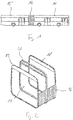
- An in Fig. 1 shown articulated bus comprises a front end 14 and a rear end 15.
- the front end 14 and the rear end 15 are connected via an in Fig. 1 not shown vehicle joint connected to each other so that passengers can change while driving through a passage 17 through between the front of the car 14 and the rear 15.
- a bellows 16 surrounds the vehicle articulation and the passage 17.
- the central hoop system according to the invention is arranged in the space between the front end 14 and the rear end 15 and in Fig. 1 hidden by the bellows 16.
- Fig. 2 shows the end frame 18 of the front end 14 and the end frame 19 of the rear carriage 15.
- the bellows 16 is in Fig. 2 only partially shown.
- a center bracket 20 is arranged, which gives the bellows 16 additional support.
- Fig. 3 extends a harness 21 between the end frame 18 and the end frame 19.
- the cables extend in the form of a uniform strand 21 through the gap between the end frame 18 and the end frame 19.
- the harness 21 takes in the space between the front end of the car 14 and the 15th a curved path that runs in the Substantially extends in a horizontal plane.
- the cable harness 21 is thus able to compensate for movements that perform the front of the car 14 and the rear carriage 15 relative to each other.
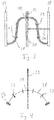
- the cable guide is shown without cable. Thereafter, the cable guide comprises a centrally located between the cables leaf spring 28 which extends parallel to the cable harness.
- the leaf spring 28 which is connected in a manner explained in more detail below with a crossbar 20 of the central bracket 20, supporting elements 23 are suspended.
- the support members 23 are according to Fig. 7 Apertures formed through which the cables of the cable harness 21 are passed. In the exemplary illustration according to Fig. 7 are each guided on both sides of the leaf spring 28 three cables. Of the total of six support members 23 which are suspended on the leaf spring 28, the middle four are arranged at the same height as the leaf spring 28. The two outer support members 23 hang slightly lower.
- the center bow 20 is according to Fig. 3 connected via a rigid handlebar 24 to the end frame 18. Both between the handlebar 24 and the end frame 18 and between the handlebar 24 and the center bracket 20, a hinge is formed, which allows pivotal movements about a vertical hinge axis. Thus, when the articulated bus travels around a curve and buckles in the lateral direction, the center bow 20 can understand the corresponding pivoting movement, so that it permanently assumes approximately a central position between the end frame 18 and the end frame 19. On the other hand, if the articulated bus drives over a knoll, so the corresponding pitching motion is compensated only between the center bracket 20 and the end frame 19. The distance between the end frame 18 and the middle bracket 20 remains constant due to the handlebar 24.
- center bow 20 is not in a middle position between end frame 18 and end frame 19.
- a rigid connection between center bow 20 would impose unnecessary longitudinal movement on wire harness 21.
- the center bow 20 can move in the longitudinal direction relative to the wire harness 21 so that the wire harness 21 is not forced to follow any longitudinal movement of the center bow 20.
- the cable guide according to the invention which makes this possible, will be explained below.
- the cable guide comprises a crossbar 22, which is arranged above an upper frame part of the central bracket 20.
- the crossbar 22 extends in the transverse direction parallel to the center bracket 20. Between the crossbar 22 and the upper frame part of the center bracket 20 remains a free space through which the cable harness 21 is guided.
- the cable harness 21 is suspended by a guide lever 25 on the crossbar 22.
- the guide lever 25 includes according to Fig. 6 a receptacle 26 in which a roller 27 is rotatably mounted.
- the receptacle 26 includes two legs which enclose the crossbar 22 between them. The also enclosed between the legs roller 27 runs on top of the crossbar 22nd
- the crossbar 22 is circular in cross section, so that the guide lever 25 is pivoted about the axis of the crossbar 22 can be.
- the roller 27 slides in such a pivoting movement in the circumferential direction on the surface of the crossbar 22nd
- the lower end of the guide lever 25 is connected to the leaf spring 28, which is arranged in the middle of the cable harness 21 and extends parallel to the cable strand 21.
- the support members 23 are suspended, in which the cables of the cable harness 21 are held.
- a pivot joint 29 is formed, whose axis is aligned parallel to the crossbar 22. If the guide lever 25 is pivoted about the crossbar 22, then the pivot joint 29 buckles. In a pivoting movement of the guide lever 25, the leaf spring 28 can thus maintain their orientation. The leaf spring 28 is only slightly lifted upwards, according to the circular path, which describes the guide lever 25 about the crossbar 22.
- a movement of the center bracket 20 relative to the wire harness 21 in the longitudinal direction is thus accommodated by a pivoting movement of the guide lever 25 about the cross bar 22.
- a movement of the center bracket 20 relative to the wire harness 21 in the transverse direction is taken by the roller 27 of the guide lever 25 along the Crossbar 22 is running.
- the cable guide is rigid.
- the cable harness 21 is held by the guide lever 25 at a defined distance from the central hoop 20 and in particular to the crossbar 22. It is thus ensured that the cable harness 21 can not strike on the central hoop 20.
- the orientation of the cable strand 21 in the longitudinal direction is kept substantially constant by the guide lever 25.
Landscapes
- Engineering & Computer Science (AREA)
- Mechanical Engineering (AREA)
- Chemical & Material Sciences (AREA)
- Combustion & Propulsion (AREA)
- Transportation (AREA)
- Electric Cable Arrangement Between Relatively Moving Parts (AREA)
- Toys (AREA)
Priority Applications (4)
| Application Number | Priority Date | Filing Date | Title |
|---|---|---|---|
| EP17153666.7A EP3354495B1 (fr) | 2017-01-30 | 2017-01-30 | Système de fourche d'articulation centrale pour un véhicule articulé |
| PL17153666T PL3354495T3 (pl) | 2017-01-30 | 2017-01-30 | System obręczy środkowej dla pojazdu wieloczłonowego |
| CA2991332A CA2991332C (fr) | 2017-01-30 | 2018-01-09 | Systeme de boucle centrale destine a un vehicule multi module |
| US15/883,122 US10576800B2 (en) | 2017-01-30 | 2018-01-30 | Middle hoop system for a multi-unit vehicle |
Applications Claiming Priority (1)
| Application Number | Priority Date | Filing Date | Title |
|---|---|---|---|
| EP17153666.7A EP3354495B1 (fr) | 2017-01-30 | 2017-01-30 | Système de fourche d'articulation centrale pour un véhicule articulé |
Publications (2)
| Publication Number | Publication Date |
|---|---|
| EP3354495A1 true EP3354495A1 (fr) | 2018-08-01 |
| EP3354495B1 EP3354495B1 (fr) | 2020-12-16 |
Family
ID=57944301
Family Applications (1)
| Application Number | Title | Priority Date | Filing Date |
|---|---|---|---|
| EP17153666.7A Active EP3354495B1 (fr) | 2017-01-30 | 2017-01-30 | Système de fourche d'articulation centrale pour un véhicule articulé |
Country Status (4)
| Country | Link |
|---|---|
| US (1) | US10576800B2 (fr) |
| EP (1) | EP3354495B1 (fr) |
| CA (1) | CA2991332C (fr) |
| PL (1) | PL3354495T3 (fr) |
Cited By (2)
| Publication number | Priority date | Publication date | Assignee | Title |
|---|---|---|---|---|
| EP3718795A1 (fr) | 2019-04-04 | 2020-10-07 | ATG Autotechnik GmbH | Guidage de câble pour un véhicule à plusieurs éléments |
| US12434778B2 (en) | 2021-08-03 | 2025-10-07 | P.E.I. Protezioni Elaborazioni Industriali S.R.L. | Device for supporting cables for articulated vehicles |
Families Citing this family (4)
| Publication number | Priority date | Publication date | Assignee | Title |
|---|---|---|---|---|
| EP3569426B1 (fr) * | 2018-05-17 | 2021-03-10 | Hübner GmbH & Co. KG | Système de guidage des conduites dans un véhicule, en particulier dans un véhicule pourvu de parties de véhicule raccordées mobiles les unes aux |
| IT202000001165A1 (it) * | 2020-01-22 | 2021-07-22 | P E I Protezioni Elaborazioni Ind S R L | Dispositivo di supporto cavi per veicoli articolati. |
| IT202100020984A1 (it) * | 2021-08-03 | 2023-02-03 | P E I Protezioni Elaborazioni Ind S R L | Dispositivo di supporto cavi flessibile per veicoli articolati. |
| CN115593452B (zh) * | 2022-10-25 | 2025-05-27 | 中车浦镇阿尔斯通运输系统有限公司 | 一种有轨车辆车厢间踏板组件结构 |
Citations (3)
| Publication number | Priority date | Publication date | Assignee | Title |
|---|---|---|---|---|
| EP0897337A1 (fr) | 1996-05-03 | 1999-02-24 | HÜBNER Gummi- und Kunststoff GmbH | Cadre central d'un soufflet, divise en deux moities, d'un element de raccordement |
| EP2384913A1 (fr) | 2010-05-05 | 2011-11-09 | ATG Autotechnik GmbH | Système de cintre moyen pour un véhicule articulé |
| DE102010011903A1 (de) * | 2010-03-18 | 2011-11-17 | Man Truck & Bus Ag | Halteeinrichtung für Leitungen an einem Gelenkfahrzeug, insbesondere an einem Gelenkbus |
Family Cites Families (6)
| Publication number | Priority date | Publication date | Assignee | Title |
|---|---|---|---|---|
| DE2854416C2 (de) * | 1978-12-16 | 1984-11-22 | M.A.N. Maschinenfabrik Augsburg-Nürnberg AG, 8000 München | Faltenbalgkupplung für einen Gelenkomnibus |
| US6076470A (en) * | 1996-05-03 | 2000-06-20 | Hubner Gummi-Und Kunststoff Gmbh | Central frame of a connecting corridor bellows subdivided in two halves |
| DE102005032218A1 (de) * | 2005-07-09 | 2007-01-11 | Hübner GmbH | Vorrichtung zum Abdecken der Spurfuge (Spurfugenabdeckung) zwischen dem Drehteller und dem Balg eines Übergangs zwischen zwei gelenkig miteinander verbundener Fahrzeugteile |
| EP2233327B1 (fr) * | 2009-03-26 | 2011-11-30 | ATG Autotechnik GmbH | Système de cintre moyen pour un véhicule articulé |
| EP2562014B1 (fr) * | 2011-08-24 | 2014-06-18 | Hübner GmbH & Co. KG | Soufflet d'un passage entre deux véhicules reliés de manière articulée d'un véhicule articulé |
| EP3208170A1 (fr) * | 2016-02-18 | 2017-08-23 | ATG Autotechnik GmbH | Systeme de cintre moyen pour un vehicule articule |
-
2017
- 2017-01-30 PL PL17153666T patent/PL3354495T3/pl unknown
- 2017-01-30 EP EP17153666.7A patent/EP3354495B1/fr active Active
-
2018
- 2018-01-09 CA CA2991332A patent/CA2991332C/fr active Active
- 2018-01-30 US US15/883,122 patent/US10576800B2/en active Active
Patent Citations (3)
| Publication number | Priority date | Publication date | Assignee | Title |
|---|---|---|---|---|
| EP0897337A1 (fr) | 1996-05-03 | 1999-02-24 | HÜBNER Gummi- und Kunststoff GmbH | Cadre central d'un soufflet, divise en deux moities, d'un element de raccordement |
| DE102010011903A1 (de) * | 2010-03-18 | 2011-11-17 | Man Truck & Bus Ag | Halteeinrichtung für Leitungen an einem Gelenkfahrzeug, insbesondere an einem Gelenkbus |
| EP2384913A1 (fr) | 2010-05-05 | 2011-11-09 | ATG Autotechnik GmbH | Système de cintre moyen pour un véhicule articulé |
Cited By (2)
| Publication number | Priority date | Publication date | Assignee | Title |
|---|---|---|---|---|
| EP3718795A1 (fr) | 2019-04-04 | 2020-10-07 | ATG Autotechnik GmbH | Guidage de câble pour un véhicule à plusieurs éléments |
| US12434778B2 (en) | 2021-08-03 | 2025-10-07 | P.E.I. Protezioni Elaborazioni Industriali S.R.L. | Device for supporting cables for articulated vehicles |
Also Published As
| Publication number | Publication date |
|---|---|
| US10576800B2 (en) | 2020-03-03 |
| CA2991332A1 (fr) | 2018-07-30 |
| EP3354495B1 (fr) | 2020-12-16 |
| CA2991332C (fr) | 2025-09-23 |
| PL3354495T3 (pl) | 2021-06-14 |
| US20180215219A1 (en) | 2018-08-02 |
Similar Documents
| Publication | Publication Date | Title |
|---|---|---|
| EP3354495B1 (fr) | Système de fourche d'articulation centrale pour un véhicule articulé | |
| EP3208171B1 (fr) | Système de cintre moyen pour un véhicule articulé | |
| EP2384913B1 (fr) | Système de cintre moyen pour un véhicule articulé | |
| EP2233327B1 (fr) | Système de cintre moyen pour un véhicule articulé | |
| DE3002672C2 (de) | Wagen für Schwebebahnen | |
| EP2700553B1 (fr) | Passage avec un pont et un soufflet circonférentiel en forme de tunnel entre deux véhicules reliés par une liaison articulée | |
| DE112009000493T5 (de) | Haltesystem | |
| DE102015214456A1 (de) | Kabinenlagerungsanordnung für ein Nutzfahrzeug | |
| EP3718795B1 (fr) | Guidage de câble pour un véhicule à plusieurs éléments | |
| DE102018118188A1 (de) | Rollwagen mit einstellbarer Kopfstütze | |
| DE102015106413B4 (de) | Scharnieranordnung | |
| EP0897337B1 (fr) | Cadre central d'un soufflet, divise en deux moities, d'un element de raccordement | |
| EP3569426B1 (fr) | Système de guidage des conduites dans un véhicule, en particulier dans un véhicule pourvu de parties de véhicule raccordées mobiles les unes aux | |
| DE19621913C1 (de) | Einrichtung zur Führung von Versorgungsleitungen | |
| DE3003996A1 (de) | Stabilisierungs-vorrichtung fuer wagen von schwebebahnen | |
| DE202023105506U1 (de) | Fahrzeugübergang | |
| EP2441636B1 (fr) | Installation destinée à déplacer des véhicules le long de deux voies de circulation | |
| EP2412600B1 (fr) | Articulation de toit pour un véhicule à plusieurs articulations | |
| EP3345804A1 (fr) | Articulation de toit pour un véhicule articulé | |
| DE102007027592A1 (de) | Fahrzeug mit gelenkig verbundenen Wagenkästen | |
| EP3046821A1 (fr) | Plateforme d'intercirculation avec zones de torsion | |
| EP2789521A1 (fr) | Caisse de voiture d'un véhicule sur rails | |
| EP0327882A3 (fr) | Installation de téléphérage | |
| DE112023001134T5 (de) | Kabelbaum-Verlegestruktur, Schwing-Schiebetür und Kabelbaum | |
| DE102012104812B4 (de) | Kraftfahrzeug mit einem feststehenden Überrollbügel |
Legal Events
| Date | Code | Title | Description |
|---|---|---|---|
| PUAI | Public reference made under article 153(3) epc to a published international application that has entered the european phase |
Free format text: ORIGINAL CODE: 0009012 |
|
| STAA | Information on the status of an ep patent application or granted ep patent |
Free format text: STATUS: THE APPLICATION HAS BEEN PUBLISHED |
|
| AK | Designated contracting states |
Kind code of ref document: A1 Designated state(s): AL AT BE BG CH CY CZ DE DK EE ES FI FR GB GR HR HU IE IS IT LI LT LU LV MC MK MT NL NO PL PT RO RS SE SI SK SM TR |
|
| AX | Request for extension of the european patent |
Extension state: BA ME |
|
| STAA | Information on the status of an ep patent application or granted ep patent |
Free format text: STATUS: REQUEST FOR EXAMINATION WAS MADE |
|
| 17P | Request for examination filed |
Effective date: 20190121 |
|
| RBV | Designated contracting states (corrected) |
Designated state(s): AL AT BE BG CH CY CZ DE DK EE ES FI FR GB GR HR HU IE IS IT LI LT LU LV MC MK MT NL NO PL PT RO RS SE SI SK SM TR |
|
| STAA | Information on the status of an ep patent application or granted ep patent |
Free format text: STATUS: EXAMINATION IS IN PROGRESS |
|
| 17Q | First examination report despatched |
Effective date: 20200415 |
|
| GRAP | Despatch of communication of intention to grant a patent |
Free format text: ORIGINAL CODE: EPIDOSNIGR1 |
|
| STAA | Information on the status of an ep patent application or granted ep patent |
Free format text: STATUS: GRANT OF PATENT IS INTENDED |
|
| INTG | Intention to grant announced |
Effective date: 20200806 |
|
| GRAS | Grant fee paid |
Free format text: ORIGINAL CODE: EPIDOSNIGR3 |
|
| GRAA | (expected) grant |
Free format text: ORIGINAL CODE: 0009210 |
|
| STAA | Information on the status of an ep patent application or granted ep patent |
Free format text: STATUS: THE PATENT HAS BEEN GRANTED |
|
| AK | Designated contracting states |
Kind code of ref document: B1 Designated state(s): AL AT BE BG CH CY CZ DE DK EE ES FI FR GB GR HR HU IE IS IT LI LT LU LV MC MK MT NL NO PL PT RO RS SE SI SK SM TR |
|
| REG | Reference to a national code |
Ref country code: GB Ref legal event code: FG4D Free format text: NOT ENGLISH |
|
| REG | Reference to a national code |
Ref country code: IE Ref legal event code: FG4D Free format text: LANGUAGE OF EP DOCUMENT: GERMAN |
|
| REG | Reference to a national code |
Ref country code: DE Ref legal event code: R096 Ref document number: 502017008659 Country of ref document: DE |
|
| REG | Reference to a national code |
Ref country code: AT Ref legal event code: REF Ref document number: 1345265 Country of ref document: AT Kind code of ref document: T Effective date: 20210115 Ref country code: CH Ref legal event code: NV Representative=s name: VALIPAT S.A. C/O BOVARD SA NEUCHATEL, CH |
|
| REG | Reference to a national code |
Ref country code: NL Ref legal event code: FP |
|
| PG25 | Lapsed in a contracting state [announced via postgrant information from national office to epo] |
Ref country code: RS Free format text: LAPSE BECAUSE OF FAILURE TO SUBMIT A TRANSLATION OF THE DESCRIPTION OR TO PAY THE FEE WITHIN THE PRESCRIBED TIME-LIMIT Effective date: 20201216 Ref country code: NO Free format text: LAPSE BECAUSE OF FAILURE TO SUBMIT A TRANSLATION OF THE DESCRIPTION OR TO PAY THE FEE WITHIN THE PRESCRIBED TIME-LIMIT Effective date: 20210316 Ref country code: FI Free format text: LAPSE BECAUSE OF FAILURE TO SUBMIT A TRANSLATION OF THE DESCRIPTION OR TO PAY THE FEE WITHIN THE PRESCRIBED TIME-LIMIT Effective date: 20201216 Ref country code: GR Free format text: LAPSE BECAUSE OF FAILURE TO SUBMIT A TRANSLATION OF THE DESCRIPTION OR TO PAY THE FEE WITHIN THE PRESCRIBED TIME-LIMIT Effective date: 20210317 |
|
| PG25 | Lapsed in a contracting state [announced via postgrant information from national office to epo] |
Ref country code: SE Free format text: LAPSE BECAUSE OF FAILURE TO SUBMIT A TRANSLATION OF THE DESCRIPTION OR TO PAY THE FEE WITHIN THE PRESCRIBED TIME-LIMIT Effective date: 20201216 Ref country code: BG Free format text: LAPSE BECAUSE OF FAILURE TO SUBMIT A TRANSLATION OF THE DESCRIPTION OR TO PAY THE FEE WITHIN THE PRESCRIBED TIME-LIMIT Effective date: 20210316 Ref country code: LV Free format text: LAPSE BECAUSE OF FAILURE TO SUBMIT A TRANSLATION OF THE DESCRIPTION OR TO PAY THE FEE WITHIN THE PRESCRIBED TIME-LIMIT Effective date: 20201216 |
|
| PG25 | Lapsed in a contracting state [announced via postgrant information from national office to epo] |
Ref country code: HR Free format text: LAPSE BECAUSE OF FAILURE TO SUBMIT A TRANSLATION OF THE DESCRIPTION OR TO PAY THE FEE WITHIN THE PRESCRIBED TIME-LIMIT Effective date: 20201216 |
|
| REG | Reference to a national code |
Ref country code: LT Ref legal event code: MG9D |
|
| PG25 | Lapsed in a contracting state [announced via postgrant information from national office to epo] |
Ref country code: SK Free format text: LAPSE BECAUSE OF FAILURE TO SUBMIT A TRANSLATION OF THE DESCRIPTION OR TO PAY THE FEE WITHIN THE PRESCRIBED TIME-LIMIT Effective date: 20201216 Ref country code: RO Free format text: LAPSE BECAUSE OF FAILURE TO SUBMIT A TRANSLATION OF THE DESCRIPTION OR TO PAY THE FEE WITHIN THE PRESCRIBED TIME-LIMIT Effective date: 20201216 Ref country code: PT Free format text: LAPSE BECAUSE OF FAILURE TO SUBMIT A TRANSLATION OF THE DESCRIPTION OR TO PAY THE FEE WITHIN THE PRESCRIBED TIME-LIMIT Effective date: 20210416 Ref country code: EE Free format text: LAPSE BECAUSE OF FAILURE TO SUBMIT A TRANSLATION OF THE DESCRIPTION OR TO PAY THE FEE WITHIN THE PRESCRIBED TIME-LIMIT Effective date: 20201216 Ref country code: SM Free format text: LAPSE BECAUSE OF FAILURE TO SUBMIT A TRANSLATION OF THE DESCRIPTION OR TO PAY THE FEE WITHIN THE PRESCRIBED TIME-LIMIT Effective date: 20201216 Ref country code: LT Free format text: LAPSE BECAUSE OF FAILURE TO SUBMIT A TRANSLATION OF THE DESCRIPTION OR TO PAY THE FEE WITHIN THE PRESCRIBED TIME-LIMIT Effective date: 20201216 |
|
| REG | Reference to a national code |
Ref country code: DE Ref legal event code: R097 Ref document number: 502017008659 Country of ref document: DE |
|
| PG25 | Lapsed in a contracting state [announced via postgrant information from national office to epo] |
Ref country code: LU Free format text: LAPSE BECAUSE OF NON-PAYMENT OF DUE FEES Effective date: 20210130 Ref country code: MC Free format text: LAPSE BECAUSE OF FAILURE TO SUBMIT A TRANSLATION OF THE DESCRIPTION OR TO PAY THE FEE WITHIN THE PRESCRIBED TIME-LIMIT Effective date: 20201216 Ref country code: IS Free format text: LAPSE BECAUSE OF FAILURE TO SUBMIT A TRANSLATION OF THE DESCRIPTION OR TO PAY THE FEE WITHIN THE PRESCRIBED TIME-LIMIT Effective date: 20210416 |
|
| PLBE | No opposition filed within time limit |
Free format text: ORIGINAL CODE: 0009261 |
|
| STAA | Information on the status of an ep patent application or granted ep patent |
Free format text: STATUS: NO OPPOSITION FILED WITHIN TIME LIMIT |
|
| PG25 | Lapsed in a contracting state [announced via postgrant information from national office to epo] |
Ref country code: AL Free format text: LAPSE BECAUSE OF FAILURE TO SUBMIT A TRANSLATION OF THE DESCRIPTION OR TO PAY THE FEE WITHIN THE PRESCRIBED TIME-LIMIT Effective date: 20201216 |
|
| 26N | No opposition filed |
Effective date: 20210917 |
|
| GBPC | Gb: european patent ceased through non-payment of renewal fee |
Effective date: 20210316 |
|
| PG25 | Lapsed in a contracting state [announced via postgrant information from national office to epo] |
Ref country code: DK Free format text: LAPSE BECAUSE OF FAILURE TO SUBMIT A TRANSLATION OF THE DESCRIPTION OR TO PAY THE FEE WITHIN THE PRESCRIBED TIME-LIMIT Effective date: 20201216 |
|
| PG25 | Lapsed in a contracting state [announced via postgrant information from national office to epo] |
Ref country code: GB Free format text: LAPSE BECAUSE OF NON-PAYMENT OF DUE FEES Effective date: 20210316 Ref country code: ES Free format text: LAPSE BECAUSE OF FAILURE TO SUBMIT A TRANSLATION OF THE DESCRIPTION OR TO PAY THE FEE WITHIN THE PRESCRIBED TIME-LIMIT Effective date: 20201216 |
|
| PG25 | Lapsed in a contracting state [announced via postgrant information from national office to epo] |
Ref country code: SI Free format text: LAPSE BECAUSE OF FAILURE TO SUBMIT A TRANSLATION OF THE DESCRIPTION OR TO PAY THE FEE WITHIN THE PRESCRIBED TIME-LIMIT Effective date: 20201216 |
|
| PG25 | Lapsed in a contracting state [announced via postgrant information from national office to epo] |
Ref country code: IS Free format text: LAPSE BECAUSE OF FAILURE TO SUBMIT A TRANSLATION OF THE DESCRIPTION OR TO PAY THE FEE WITHIN THE PRESCRIBED TIME-LIMIT Effective date: 20210416 |
|
| PG25 | Lapsed in a contracting state [announced via postgrant information from national office to epo] |
Ref country code: CY Free format text: LAPSE BECAUSE OF FAILURE TO SUBMIT A TRANSLATION OF THE DESCRIPTION OR TO PAY THE FEE WITHIN THE PRESCRIBED TIME-LIMIT Effective date: 20201216 |
|
| PG25 | Lapsed in a contracting state [announced via postgrant information from national office to epo] |
Ref country code: HU Free format text: LAPSE BECAUSE OF FAILURE TO SUBMIT A TRANSLATION OF THE DESCRIPTION OR TO PAY THE FEE WITHIN THE PRESCRIBED TIME-LIMIT; INVALID AB INITIO Effective date: 20170130 |
|
| P01 | Opt-out of the competence of the unified patent court (upc) registered |
Effective date: 20230911 |
|
| PG25 | Lapsed in a contracting state [announced via postgrant information from national office to epo] |
Ref country code: MK Free format text: LAPSE BECAUSE OF FAILURE TO SUBMIT A TRANSLATION OF THE DESCRIPTION OR TO PAY THE FEE WITHIN THE PRESCRIBED TIME-LIMIT Effective date: 20201216 |
|
| PG25 | Lapsed in a contracting state [announced via postgrant information from national office to epo] |
Ref country code: MT Free format text: LAPSE BECAUSE OF FAILURE TO SUBMIT A TRANSLATION OF THE DESCRIPTION OR TO PAY THE FEE WITHIN THE PRESCRIBED TIME-LIMIT Effective date: 20201216 |
|
| PGFP | Annual fee paid to national office [announced via postgrant information from national office to epo] |
Ref country code: PL Payment date: 20250120 Year of fee payment: 9 |
|
| REG | Reference to a national code |
Ref country code: CH Ref legal event code: U11 Free format text: ST27 STATUS EVENT CODE: U-0-0-U10-U11 (AS PROVIDED BY THE NATIONAL OFFICE) Effective date: 20260201 |
|
| PGFP | Annual fee paid to national office [announced via postgrant information from national office to epo] |
Ref country code: NL Payment date: 20260121 Year of fee payment: 10 |
|
| PGFP | Annual fee paid to national office [announced via postgrant information from national office to epo] |
Ref country code: DE Payment date: 20260120 Year of fee payment: 10 Ref country code: IE Payment date: 20260121 Year of fee payment: 10 |
|
| PGFP | Annual fee paid to national office [announced via postgrant information from national office to epo] |
Ref country code: AT Payment date: 20260119 Year of fee payment: 10 |
|
| PGFP | Annual fee paid to national office [announced via postgrant information from national office to epo] |
Ref country code: BE Payment date: 20260121 Year of fee payment: 10 Ref country code: IT Payment date: 20260130 Year of fee payment: 10 |
|
| PGFP | Annual fee paid to national office [announced via postgrant information from national office to epo] |
Ref country code: FR Payment date: 20260121 Year of fee payment: 10 |
|
| PGFP | Annual fee paid to national office [announced via postgrant information from national office to epo] |
Ref country code: TR Payment date: 20260127 Year of fee payment: 10 |
|
| PGFP | Annual fee paid to national office [announced via postgrant information from national office to epo] |
Ref country code: CZ Payment date: 20260116 Year of fee payment: 10 Ref country code: CH Payment date: 20260201 Year of fee payment: 10 |