EP3354801A1 - Vorrichtung zum befestigen von anbaugeräten an baggerauslegern - Google Patents
Vorrichtung zum befestigen von anbaugeräten an baggerauslegern Download PDFInfo
- Publication number
- EP3354801A1 EP3354801A1 EP18153110.4A EP18153110A EP3354801A1 EP 3354801 A1 EP3354801 A1 EP 3354801A1 EP 18153110 A EP18153110 A EP 18153110A EP 3354801 A1 EP3354801 A1 EP 3354801A1
- Authority
- EP
- European Patent Office
- Prior art keywords
- coupling
- hydraulic
- electrical
- quick
- mounting plate
- Prior art date
- Legal status (The legal status is an assumption and is not a legal conclusion. Google has not performed a legal analysis and makes no representation as to the accuracy of the status listed.)
- Granted
Links
Images



Classifications
-
- E—FIXED CONSTRUCTIONS
- E02—HYDRAULIC ENGINEERING; FOUNDATIONS; SOIL SHIFTING
- E02F—DREDGING; SOIL-SHIFTING
- E02F3/00—Dredgers; Soil-shifting machines
- E02F3/04—Dredgers; Soil-shifting machines mechanically-driven
- E02F3/28—Dredgers; Soil-shifting machines mechanically-driven with digging tools mounted on a dipper- or bucket-arm, i.e. there is either one arm or a pair of arms, e.g. dippers, buckets
- E02F3/36—Component parts
- E02F3/3604—Devices to connect tools to arms, booms or the like
- E02F3/3609—Devices to connect tools to arms, booms or the like of the quick acting type, e.g. controlled from the operator seat
- E02F3/3654—Devices to connect tools to arms, booms or the like of the quick acting type, e.g. controlled from the operator seat with energy coupler, e.g. coupler for hydraulic or electric lines, to provide energy to drive(s) mounted on the tool
-
- E—FIXED CONSTRUCTIONS
- E02—HYDRAULIC ENGINEERING; FOUNDATIONS; SOIL SHIFTING
- E02F—DREDGING; SOIL-SHIFTING
- E02F3/00—Dredgers; Soil-shifting machines
- E02F3/04—Dredgers; Soil-shifting machines mechanically-driven
- E02F3/28—Dredgers; Soil-shifting machines mechanically-driven with digging tools mounted on a dipper- or bucket-arm, i.e. there is either one arm or a pair of arms, e.g. dippers, buckets
- E02F3/36—Component parts
- E02F3/3604—Devices to connect tools to arms, booms or the like
- E02F3/3609—Devices to connect tools to arms, booms or the like of the quick acting type, e.g. controlled from the operator seat
- E02F3/3627—Devices to connect tools to arms, booms or the like of the quick acting type, e.g. controlled from the operator seat with a hook and a longitudinal locking element
-
- E—FIXED CONSTRUCTIONS
- E02—HYDRAULIC ENGINEERING; FOUNDATIONS; SOIL SHIFTING
- E02F—DREDGING; SOIL-SHIFTING
- E02F3/00—Dredgers; Soil-shifting machines
- E02F3/04—Dredgers; Soil-shifting machines mechanically-driven
- E02F3/28—Dredgers; Soil-shifting machines mechanically-driven with digging tools mounted on a dipper- or bucket-arm, i.e. there is either one arm or a pair of arms, e.g. dippers, buckets
- E02F3/36—Component parts
- E02F3/3604—Devices to connect tools to arms, booms or the like
- E02F3/3609—Devices to connect tools to arms, booms or the like of the quick acting type, e.g. controlled from the operator seat
- E02F3/3663—Devices to connect tools to arms, booms or the like of the quick acting type, e.g. controlled from the operator seat hydraulically-operated
Definitions
- the invention relates to a device for fastening an attachment to an excavator boom, comprising a quick-change device and a mounting plate having the features of the introductory part of claim 1.
- Such devices which allow the attachment and change of attachments at the free end of an excavator boom, are known. For example, this can be up AT 002 087 U1 . WO 98/46835 A1 . AT 413 117 B1 and AT 008 070 U1 to get expelled.
- an attachment is to be defined on the excavator boom, which itself has a hydraulic device, such as hydraulic hammers or slope spoons, it is necessary to connect the hydraulic lines leading to the hydraulic device on the attachment with the hydraulic lines coming from the excavator, after the attachment at the free end of the excavator boom has been fixed by means of the quick-change device and the mounting plate, so that the operation and the use of the attachment can be controlled from the cab of the excavator.
- a hydraulic device such as hydraulic hammers or slope spoons
- a device comprising a quick-change device and a mounting plate, in which when attaching an attachment at the free end of an excavator boom, the connection of the hydraulic equipment leading to the attachment is done automatically, is off AT 008 623 U2 or EP 1 840 276 A2 known.
- a device for connecting attachments with an excavator boom consisting of an attached to the excavator boom quick-change device and attached to the attachment mounting plate.
- the well-known Device has at least one coupling for connecting at least one hydraulic line coming from the excavator to a hydraulic line leading to a hydraulic drive motor (hydraulic cylinder) provided on the attachment.
- the at least one hydraulic clutch is actuated by a clutch cylinder after the locking cylinder has advanced the latch to its operative position.
- an electrical connection between the excavator and an attachment is required. This is the case, for example, when a spoiler is equipped with a leveling device to allow for predetermined inclinations, e.g. on slopes, via GPS control.
- an electrical device can also be provided in an attachment processors for activating electrical equipment, such as those in wood processors (forestry work).
- WO 2004/072387 A1 shows a coupling comprising a quick-change device and a mounting plate with sensors to indicate the proper coupling.
- the sensors include sensor elements on the quick-change device and sensor counterparts on the attachment plate.
- the position of the bars is detected by a detector, which is arranged on the yoke of the bolt, and a sensor on the mounting plate.
- WO 2004/072387 A1 indicates that the sensors can be "electrical" sensors.
- FR 2 676 765 A1 shows, inter alia, electrical couplings. Part of the couplings is fixed to the hook side of a quick-change device and the other parts are also fixedly attached to the mounting plate.
- WO 2010/062193 A1 shows and describes a hydraulic clutch. Part of the coupling is adjustable with the bolt. The other part is mounted on the mounting plate. References to an electrical coupling can be found in WO 2010/062193 A1 Not.
- AT 505 238 A1 shows a clutch, which may also be an electrical coupling.
- the coupling comprises two coupling parts, which are arranged facing each other. One part is permanently attached to the quick-change device and the other part to the mounting plate. The coupling should be closed when swiveling quick-change device and mounting plate in its coupled position.
- DE 601 02 71 T2 shows and describes an electrical coupling to a coupling device for connecting tools with an excavator boom.
- a hydraulic clutch is to be closed when connecting a quick-change device with a mounting plate by a part of the hydraulic clutch is moved.
- AT 513 587 A1 shows a coupling device comprising electrical and hydraulic coupling elements, which are provided on the one hand on a quick coupler and on the other hand on a mounting plate.
- the invention is based on the object EP 2 233 642 A1 known device such that not only a coupling of hydraulic lines, but also the coupling of at least one electrical line that leads from the excavator to the attachment, is possible.
- the parts of the electrical coupling are arranged on the side remote from the attachment side of the hydraulic coupling parts.
- a particularly favorable, spatial arrangement of the coupling parts of the at least one electrical coupling is given and reduces the risk of contamination of the electrical coupling.
- an additional, open towards the bolt receptacle recess for receiving the provided on the mounting plate coupling part of the electric coupling can be provided.
- This recess may be formed in a recess in the upper part of the bolt receptacle or it is the upper web of the bolt receptacle interrupted to make room for the provided on the mounting plate part of the electrical coupling.
- the device shown comprises a quick-change device 1, which at the free end of a (not shown) and a mounting plate 2, which is connected to an attachment 3, such as a hydraulic hammer (not shown), or a battering scoop.
- an attachment 3 such as a hydraulic hammer (not shown), or a battering scoop.
- a pressure medium cylinder preferably a hydraulic cylinder, provided and coupled with the bars 4.
- the piston rod 13 of the hydraulic cylinder extends, so that the connection between the coupling plugs 12, which are fixed to the block 10, and coupling sleeves 14, which are arranged on a block 15 mounted on the mounting plate 2 in the region of the bolt receptacle 5, and the hydraulic couplings are closed.
- the block 15 with the coupling sleeves 14 is arranged on the mounting plate 2. From the coupling plug 12 bearing block 10 guide pins can protrude, which engage in closed hydraulic coupling in guide holes in the coupling sleeves 14 bearing block 15.
- a protective element 30 in the form of a particularly elastic plate, cf. FIG. 2 can be attached to the mounting plate 2 on the block 15 instead of the coupling sleeves 14 and the socket 26. AT 10 695 U1 ) be provided to protect the provided on the quick-change device 1 coupling plug 12 and plug 20.
- an electrical connector 20 is provided on the block 10, which carries the coupling connector 12 for the hydraulic lines 11.
- a plurality of electrical contacts 21 are provided in the electrical connector 20, a plurality of electrical contacts 21 are provided.
- the electrical connector 20 disposed on the side facing away from the mounting plate 2 side of the coupling connector 12 for the hydraulic lines 11, that is from the mounting plate 2 is further away than the coupling connector 12th
- a recess 23 is provided in the bolt guide 9 at its side facing away from the mounting plate 2 edge, to make room for the part 33 of the block 10, which carries the electrical connector 20.
- a block 15 is provided in the designated there, intended for the engagement of the latch 4 opening 7, which carries the coupling sleeves 14 for connecting the hydraulic lines 13 and 16.
- the block 15 is mounted on a support 24 which is fixed to the mounting plate 2 with screws 25.
- a socket 26 is provided on the block 15. From the socket 26, an electrical line 27 goes out, which leads to an electrical device on the attachment 3.
- Fig. 1 shows, the opening 7 in the latch receptacle 5 is formed so that also for the electrical socket 26 in the part 29 of the block 15 which receives the socket 26, space is created, so that the block 15 is disposed in the opening 7 of the latch receptacle 5 can be.
- the 4 to 6 show a symmetrically shaped mounting plate 2, in which the recess 28 is formed for the part 29 of the block 15 which carries the electrical socket 26 as an interruption 32 of the remote from the attachment 3 web 31 of the bolt receptacle 5.
- asymmetric mounting plates 2 ( Fig. 1 and 2 ) and in particular symmetrically shaped mounting plates ( 4 to 6 ), which are used for attachments 3 without hydraulic device and without electrical device, instead of the coupling sleeves 14 and the electrical socket 26, a protective element 30 in the form of a (elastic) plate ( AT 10 695 U1 ).
- a protective element 30 in the form of a (elastic) plate ( AT 10 695 U1 ).
- the block 10 sets with its edge 18 sealingly, so that the hydraulic coupling plug 12 and the electrical connector 20, which are provided on the quick-change device 1, are protected and in particular can not pollute.
Landscapes
- Engineering & Computer Science (AREA)
- Mechanical Engineering (AREA)
- Mining & Mineral Resources (AREA)
- Civil Engineering (AREA)
- General Engineering & Computer Science (AREA)
- Structural Engineering (AREA)
- Operation Control Of Excavators (AREA)
- Shovels (AREA)
Abstract
Description
- Die Erfindung betrifft eine Vorrichtung zum Befestigen eines Anbaugerätes an einem Baggerausleger, umfassend eine Schnellwechselvorrichtung und eine Anbauplatte mit den Merkmalen des einleitenden Teils von Anspruch 1.
- Derartige Vorrichtungen, die das Befestigen und das Wechseln von Anbaugeräten am freien Ende eines Baggerauslegers erlauben, sind bekannt. Beispielsweise kann hierzu auf
AT 002 087 U1 WO 98/46835 A1 AT 413 117 B1 AT 008 070 U1 - Die bekannten Vorrichtungen haben sich gut bewährt, da sie ein rasches Befestigen von Anbaugeräten (Löffel, Hydraulikhämmer und Ähnliches) an Baggerauslegern erlauben und den sicheren Sitz des Anbaugerätes am Baggerausleger gewährleisten.
- Wenn am Baggerausleger ein Anbaugerät festzulegen ist, das selbst eine Hydraulikeinrichtung aufweist, wie beispielsweise Hydraulikhämmer oder Böschungslöffel, ist es erforderlich, die Hydraulikleitungen, die zu der Hydraulikeinrichtung am Anbaugerät führen, mit den vom Bagger kommenden Hydraulikleitungen zu verbinden, nachdem das Anbaugerät am freien Ende des Baggerauslegers mit Hilfe der Schnellwechselvorrichtung und der Anbauplatte befestigt worden ist, damit der Betrieb und das Benützen des Anbaugerätes vom Führerstand des Baggers aus gesteuert werden kann.
- Eine Vorrichtung umfassend eine Schnellwechselvorrichtung und eine Anbauplatte, bei der beim Befestigen eines Anbaugerätes am freien Ende eines Baggerauslegers das Verbinden der zum Anbaugerät führenden Hydraulikleitungen selbsttätig erfolgt, ist aus
AT 008 623 U2 EP 1 840 276 A2 bekannt. - Aus
EP 2 233 642 A1 ist eine Vorrichtung zum Verbinden von Anbaugeräten mit einem Baggerausleger bestehend aus einer am Baggerausleger befestigten Schnellwechselvorrichtung und einer am Anbaugerät befestigten Anbauplatte bekannt. Die bekannte Vorrichtung besitzt wenigstens eine Kupplung für das Verbinden von wenigstens einer vom Bagger kommenden Hydraulikleitung mit einer Hydraulikleitung, die zu einem am Anbaugerät vorgesehenen, hydraulischen Antriebsmotor (Hydraulikzylinder) führt. Die wenigstens eine Hydraulikkupplung wird durch einen Kupplungszylinder betätigt, nachdem der Verriegelungszylinder die Riegel in ihre Wirkstellung vorgeschoben hat. So ist beim Festlegen eines Anbaugerätes mit Hilfe der bekannten Vorrichtung an einem Baggerausleger gewährleistet, dass wenigstens ein in einem Anbaugerät vorgesehener Antriebsmotor (Hydraulikzylinder) mit Hydraulikmedium beaufschlagt werden kann. - In bestimmten Fällen ist auch eine elektrische Verbindung zwischen dem Bagger und einem Anbaugerät erforderlich. Das ist beispielsweise der Fall, wenn ein Böschungslöffel mit einer Nivelliereinrichtung ausgestattet ist, um vorgegebene Neigungen, z.B. an Böschungen, über GPS zu steuern.
- Als elektrische Einrichtung können in einem Anbaugerät auch Prozessoren zum Aktivieren elektrischer Geräte, wie solche in Holzprozessoren (Forstarbeit), vorgesehen sein.
-
WO 2004/072387 A1 zeigt eine Kupplung, umfassend eine Schnellwechselvorrichtung und eine Anbauplatte mit Sensoren, die das ordnungsgemäße Kuppeln anzeigen sollen. Die Sensoren umfassen Sensor-Elemente an der Schnellwechselvorrichtung und Sensor-Gegenstücke an der Anbauplatte. Die Stellung der Riegel wird von einem Detektor, der am Joch der Riegel angeordnet ist, und einen Sensor an der Anbauplatte erfasst.WO 2004/072387 A1 deutet an, dass die Sensoren "elektrische" Sensoren sein können. -
FR 2 676 765 A1 -
DE 196 39 217 A1 offenbart, dass an der Kupplungsstelle einer landwirtschaftlichen Maschine elektrische Kupplungen vorgesehen sind. Diese sind an den Teilen der Kupplung fest "installiert". -
WO 2010/062193 A1 zeigt und beschreibt eine Hydraulikkupplung. Ein Teil der Kupplung ist mit dem Riegel verstellbar. Der andere Teil ist an der Anbauplatte montiert. Hinweise auf eine elektrische Kupplung finden sich inWO 2010/062193 A1 nicht. -
AT 505 238 A1 -
DE 601 02 71 T2 zeigt und beschreibt eine elektrische Kupplung an einer Kupplungsvorrichtung zum Verbinden von Werkzeugen mit einem Baggerausleger. - Gemäß
EP 2 103 744 A1 soll eine Hydraulikkupplung beim Verbinden einer Schnellwechselvorrichtung mit einer Anbauplatte geschlossen werden, indem ein Teil der Hydraulikkupplung verschoben wird. -
AT 513 587 A1 - Der Erfindung liegt die Aufgabe zugrunde, die aus
EP 2 233 642 A1 bekannte Vorrichtung derart weiterzubilden, dass nicht nur ein Kuppeln von Hydraulikleitungen, sondern auch das Kuppeln wenigstens einer elektrischen Leitung, die vom Bagger zum Anbaugerät führt, möglich ist. - Gelöst wird diese Aufgabe mit einer Vorrichtung, welche die Merkmale von Anspruch 1 aufweist.
- Bevorzugte und vorteilhafte Ausgestaltungen der erfindungsgemäßen Vorrichtung sind Gegenstand der Unteransprüche.
- Da bei der erfindungsgemäßen Vorrichtung an dem in der Schnellwechselvorrichtung vorgesehenen, von einem Motor (Druckmittelzylinder) verschiebbaren Block (= Schubstück) nicht nur Kupplungsteile für wenigstens eine Hydraulikkupplung, sondern auch wenigstens ein Kupplungsteil für eine elektrische Kupplung vorgesehen sind und weiters im Bereich der Riegelaufnahme der Anbauplatte zusätzlich zu den Kupplungsteilen für die wenigstens eine Hydraulikkupplung auch wenigstens ein Kupplungsteil für eine elektrische Kupplung vorgesehen ist, wird beim Schließen der Hydraulikkupplung auch gleichzeitig eine elektrische Verbindung in der wenigstens einen elektrischen Leitung zwischen Bagger und Anbaugerät hergestellt.
- Bei einer Ausführungsform der erfindungsgemäßen Vorrichtung ist es von Vorteil, wenn die Teile der elektrischen Kupplung (Stecker und Steckbuchse) auf der vom Anbaugerät entfernt liegenden Seite der Hydraulikkupplungsteile angeordnet sind. So ist eine besonders günstige, räumliche Anordnung der Kupplungsteile der wenigstens einen elektrischen Kupplung gegeben und die Gefahr des Verschmutzens der elektrischen Kupplung verringert.
- In einer Ausführungsform der Erfindung ist vorgesehen, dass für die Kupplungsteile der elektrischen Kupplung in der an der Schnellwechselvorrichtung vorgesehenen Riegelführung eine zur Riegelführung hin offene Aussparung für den an der Schnellwechselvorrichtung vorgesehenen Kupplungsteil der elektrischen Kupplung vorgesehen ist.
- Sinngemäß kann in der Riegelaufnahme, insbesondere in dem gestuften Bereich derselben, eine zusätzliche, zur Riegelaufnahme hin offene Aussparung für die Aufnahme des an der Anbauplatte vorgesehenen Kupplungsteils der elektrischen Kupplung vorgesehen sein.
- Diese Aussparung kann in einer Ausnehmung im oberen Teil der Riegelaufnahme gebildet sein oder aber es ist der obere Steg der Riegelaufnahme unterbrochen, um Platz für den an der Anbauplatte vorgesehenen Teil der elektrischen Kupplung zu schaffen.
- Weitere Einzelheiten und Merkmale der Erfindung ergeben sich aus der nachstehenden Beschreibung bevorzugter Ausführungsbeispiele. Es zeigt:
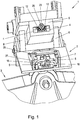
- Fig. 1
- in Schrägansicht eine erfindungsgemäße Vorrichtung an einem Böschungslöffel, wobei die Anbauplatte mit der Schnellwechselvorrichtung noch nicht vollständig verbunden ist,
- Fig. 2
- in einer anderen Ansicht die Anbauplatte und den Böschungslöffel von
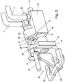
Fig. 1 , - Fig. 3
- in weitgehend schematisierter Schrägansicht einen Block mit den Kupplungsteilen für die elektrische und die hydraulische Kupplung und das an der Anbauplatte im Bereich der Riegelaufnahme anzubringende Gegenstück,
- Fig. 4
- eine symmetrisch ausgebildete Anbauplatte mit einem an der Anbauplatte vorgesehenen Schutzelement für die Teile der elektrischen und der hydraulischen Kupplung an der Schnellwechselvorrichtung,
- Fig. 5
- eine vergrößerte Einzelheit von
Fig. 4 und - Fig. 6
- eine weitere Einzelheit der Anbauplatte von
Fig. 4 ohne Schutzelement. - Eine in
Fig. 1 gezeigte Vorrichtung umfasst eine Schnellwechselvorrichtung 1, die am freien Ende eines (nicht gezeigten) Baggerauslegers oder dgl. angeordnet ist, und eine Anbauplatte 2, die mit einem Anbaugerät 3, z.B. einem Hydraulikhammer (nicht gezeigt), oder einem Böschungslöffel verbunden ist. Durch vor- und zurückschiebbare Riegel 4, die beispielsweise keilförmig ausgebildet und in eine entsprechend geformte Öffnung 7 in einer Riegelaufnahme 5 an der Anbauplatte 3 einschiebbar sind, sowie über an der Schnellwechselvorrichtung 1 vorgesehene (starre) Haken 6, die hinter eine Kupplungsstange 8 (Aufnahmebolzen) an der Anbauplatte 2 eingreifen, kann die Anbauplatte 2 an der Schnellwechselvorrichtung 1 festgelegt werden. - Zum Verstellen der Riegel 4, die beispielsweise in einem kastenartigen Aufnahmeraum der Schnellwechselvorrichtung 1 vorgesehen sind, ist als Verriegelungszylinder ein Druckmittelzylinder, vorzugsweise ein Hydraulikzylinder, vorgesehen und mit den Riegeln 4 gekuppelt. Durch Betätigen des Verriegelungszylinders werden die Riegel 4 durch eine Riegelführung 9 in ihre Wirkstellung, in der sie in die Öffnung 7 der Riegelaufnahme 5 an der Anbauplatte 2 des Anbaugerätes 3 eingreifen, verschoben und verbinden das Anbaugerät 3 sicher mit der Schnellwechselvorrichtung 1.
- Vom Bagger zu der Schnellwechselvorrichtung 1 führende Hydraulikleitungen 11 sind an einem Block 10 angeschlossen, an dem Kupplungsstecker 12 montiert sind. Der Block 10 ist an der Kolbenstange 13 eines an der Schnellwechselvorrichtung 1 montierten Hydraulikzylinders montiert. Dabei ist vorgesehen, dass zunächst der die Riegel 4 betätigende Verrieglungszylinder der Schnellwechselvorrichtung 1 mit Hydraulikmedium beaufschlagt wird, um die Riegel 4 auszufahren, sodass die Anbauplatte 2 des Arbeitsgerätes 3 mit der Schnellwechselvorrichtung 1 gekuppelt wird. Sobald beim Beaufschlagen des Verriegelungszylinders ein vorgegebener Druck, beispielsweise ein Druck von 120 bar, erreicht wird, wird über ein Druckfolgeventil der für das Verschieben des Blockes 10 vorgesehene Hydraulikzylinder mit Hydraulikmedium beaufschlagt. Die Kolbenstange 13 des Hydraulikzylinders fährt aus, sodass die Verbindung zwischen den Kupplungssteckern 12, die am Block 10 befestigt sind, und Kupplungsmuffen 14, die an einem an der Anbauplatte 2 im Bereich der Riegelaufnahme 5 montierten Block 15 angeordnet sind, hergestellt wird und die Hydraulikkupplungen geschlossen sind. Der Block 15 mit den Kupplungsmuffen 14 ist an der Anbauplatte 2 angeordnet. Von dem die Kupplungsstecker 12 tragenden Block 10 können Führungsstifte abstehen, die bei geschlossener Hydraulikkupplung in Führungslöcher in dem die Kupplungsmuffen 14 tragenden Block 15 eingreifen.
- Zu dem mit der Kolbenstange 13 des Hydraulikzylinders verbundenen Block 10 führen zwei Hydraulikleitungen 11. Von dem Block 15 an der Anbauplatte 2 führen zwei weitere Hydraulikleitungen 16 weg, über die im Anbaugerät 3, z. B. dem Böschungslöffel (
Fig. 1 und2 ), vorgesehene Hydraulikzylinder mit Hydraulikmedium beaufschlagt werden können. - Wenn die erfindungsgemäße Vorrichtung für Anbaugeräte 3 ohne eigene Hydraulikeinrichtung oder elektrische Einrichtung verwendet wird, kann an der Anbauplatte 2 an dem Block 15 an Stelle der Kupplungsmuffen 14 und Steckbuchse 26 ein Schutzelement 30 (in Form einer insbesondere elastischen Platte, vgl.
AT 10 695 U1 - Bei der erfindungsgemäßen Schnellwechselvorrichtung 1 ist an dem Block 10, der die Kupplungsstecker 12 für die Hydraulikleitungen 11 trägt, auch ein elektrischer Stecker 20 vorgesehen. In dem elektrischen Stecker 20 sind mehrere elektrische Kontakte 21 vorgesehen. Zu den elektrischen Kontakten 21 führt eine (mehrpolige) Leitung 22.
- Dabei ist vorgesehen, dass der elektrische Stecker 20 auf der von der Anbauplatte 2 abgekehrten Seite der Kupplungsstecker 12 für die Hydraulikleitungen 11 angeordnet, also von der Anbauplatte 2 weiter entfernt ist als die Kupplungsstecker 12.
- Hierzu ist in der Riegelführung 9 an ihrem von der Anbauplatte 2 abgekehrten Rand eine Ausnehmung 23 vorgesehen, um Platz für den Teil 33 des Blockes 10 zu schaffen, der den elektrischen Stecker 20 trägt.
- Im Bereich der Riegelaufnahme 5 an der Anbauplatte 2 ist in der dort vorgesehenen, für den Eingriff der Riegel 4 bestimmten Öffnung 7 ein Block 15 vorgesehen, der die Kupplungsmuffen 14 für das Verbinden der Hydraulikleitungen 13 und 16 trägt. Wie beispielsweise
Fig. 3 und auchFig. 1 zeigen, ist der Block 15 an einem Träger 24 angebracht, der an der Anbauplatte 2 mit Schrauben 25 befestigt ist. - Auf der vom Anbaugerät 3 abgekehrten Seite der Kupplungsmuffen 14 für die Hydraulikleitungen 16 ist an dem Block 15 eine Steckbuchse 26 vorgesehen. Von der Steckbuchse 26 geht eine elektrische Leitung 27 aus, die zu einer elektrischen Einrichtung am Anbaugerät 3 führt.
- Wie insbesondere
Fig. 1 zeigt, ist die Öffnung 7 in der Riegelaufnahme 5 so ausgebildet, dass auch für die elektrische Steckbuchse 26 im Teil 29 des Blockes 15, der die Steckbuchse 26 aufnimmt, Raum geschaffen wird, so dass der Block 15 in der Öffnung 7 der Riegelaufnahme 5 angeordnet sein kann. - Hierzu ist bei der in
Fig. 1 gezeigten Ausführungsform der von dem Anbaugerät 3 abgekehrte Rand der Öffnung 7 in der Riegelaufnahme 5 nicht nur gestuft ausgebildet, sondern es ist in dem gestuften Bereich noch eine Ausnehmung 28 vorgesehen, in die der Teil 29 des Blockes 15, der die elektrische Steckbuchse 26 trägt, aufgenommen ist. - Wenn der Block 10 mit den hydraulischen Kupplungssteckern 12 und dem elektrischen Stecker 20 so weit vorgeschoben ist, dass die Kupplungsstecker 12 in die Kupplungsmuffen 14 am Block 15 und der Stecker 20 in die Steckbuchse 26 am Block 15 eingreifen, liegt der Block 10 mit seinem vorstehenden Rand 18 an der ihm zugekehrten Fläche des Blocks 15 an. So sind die elektrischen und die hydraulischen Kupplungen vor Feuchtigkeit und Schmutz geschützt.
- Die
Fig. 4 bis 6 zeigen eine symmetrisch ausgebildete Anbauplatte 2, bei der die Ausnehmung 28 für den Teil 29 des Blockes 15, der die elektrische Steckbuchse 26 trägt, als Unterbrechung 32 des vom Anbaugerät 3 abgekehrten Steges 31 der Riegelaufnahme 5 ausgebildet ist. - Es ist in Betracht gezogen, an asymmetrischen Anbauplatten 2 (
Fig. 1 und2 ) und insbesondere an symmetrisch ausgebildeten Anbauplatten (Fig. 4 bis 6 ), die für Anbaugeräte 3 ohne hydraulische Einrichtung und ohne elektrische Einrichtung verwendet werden, an Stelle der Kupplungsmuffen 14 und der elektrischen Steckbuchse 26 ein Schutzelement 30 in Form einer (elastischen) Platte (AT 10 695 U1 - Zusammenfassend kann ein Ausführungsbeispiel der Erfindung wie folgt beschrieben werden:
- An einer Vorrichtung zum Verbinden eines Anbaugerätes 3 mit einem Baggerausleger sind wenigstens eine Hydraulikkupplung und wenigstens eine elektrische Kupplung vorgesehen. Die Teile der Kupplungen werden nach dem Ansetzen der Schnellwechselvorrichtung 1 an die am Arbeitsgerät 3 befestigte Anbauplatte 2 miteinander verbunden. Die Teile der Hydraulikkupplung und jene der elektrischen Kupplung sind einerseits im Bereich der Riegelführung 9 der Schnellwechselvorrichtung 1 und anderseits im Bereich der Riegelaufnahme 5 der Anbauplatte 2 angeordnet. Die Teile der elektrischen Kupplung sind an der Schnellwechselvorrichtung 1 auf der dem Baggerausleger zugewendeten Seite und an der Anbauplatte 2 auf der vom Anbaugerät 3 abgewandten Seite der Teile der Hydraulikkupplung angeordnet.
Claims (10)
- Vorrichtung zum Verbinden eines Arbeitsgerätes (3) mit einem Baggerausleger, umfassend eine Schnellwechselvorrichtung (1) und eine Anbauplatte (2), wobei wenigstens eine Hydraulikkupplung vorgesehen ist, mit der wenigstens eine vom Bagger kommende Hydraulikleitung (11) mit wenigstens einer Hydraulikleitung (16), die zu wenigstens einer Hydraulikeinrichtung im Anbaugerät(3) führt, verbindbar ist, wobei an der Schnellwechselvorrichtung (1) ein Teil, insbesondere der Kupplungsstecker (12) der Hydraulikkupplung, und an der Anbauplatte (3) ein weiterer Teil, insbesondere die Kupplungsmuffe (14) der Hydraulikkupplung, vorgesehen ist, dadurch gekennzeichnet, dass wenigstens eine elektrische Kupplung vorgesehen ist, mit der wenigstens eine vom Bagger kommende elektrische Leitung (22) mit wenigstens einer zu einer im Anbaugerät (3) vorgesehenen elektrischen Einrichtung führenden elektrischen Leitung (27) verbindbar ist.
- Vorrichtung nach Anspruch 1, dadurch gekennzeichnet, dass ein Teil der elektrischen Kupplung an einem in der Schnellwechselvorrichtung (1) verschiebbaren Block (10), der einen Teil der Hydraulikkupplung trägt, angeordnet ist.
- Vorrichtung nach Anspruch 2, dadurch gekennzeichnet, dass der Teil der elektrischen Kupplung im Bereich einer an der Schnellwechselvorrichtung (1) vorgesehenen Riegelführung (9) vor und zurück verschiebbar ist.
- Vorrichtung nach Anspruch 2 oder 3, dadurch gekennzeichnet, dass ein weiterer Teil der elektrischen Kupplung in einer Öffnung (7) in einer an der Anbauplatte (2) vorgesehenen Riegelaufnahme (5) angeordnet ist.
- Vorrichtung nach einem der Ansprüche 1 bis 4, dadurch gekennzeichnet, dass der an der Schnellwechselvorrichtung (1) vorgesehene Teil der elektrischen Kupplung auf der dem Baggerausleger zugekehren Seite der Teile der Hydraulikkupplung angeordnet ist.
- Vorrichtung nach einem der Ansprüche 1 bis 5, dadurch gekennzeichnet, dass der an der Anbauplatte (2) vorgesehene Teil der elektrischen Kupplung auf der von einem Anbaugerät (3) abgekehrten Seite der Teile der Hydraulikkupplung angeordnet ist.
- Vorrichtung nach einem der Ansprüche 1 bis 6, dadurch gekennzeichnet, dass in der Riegelführung (9) eine zum Inneren der Riegelführung hin offene Ausnehmung (23) für einen Teil der elektrischen Kupplung vorgesehen ist.
- Vorrichtung nach einem der Ansprüche 4 bis 7, dadurch gekennzeichnet, dass in dem vom Anbaugerät (3) entfernt liegenden Steg der Riegelaufnahme (5) eine zum Inneren der Riegelaufnahme (5) hin offene Ausnehmung (28) für einen Teil der elektrischen Kupplung vorgesehen ist.
- Vorrichtung nach Anspruch 8, dadurch gekennzeichnet, dass die Ausnehmung (28) durch eine Unterbrechung des Steges der Riegelaufnahme (5) gebildet ist.
- Vorrichtung nach einem der Ansprüche 1 bis 9, dadurch gekennzeichnet, dass zwei Hydraulikkupplungen und eine elektrische Kupplung vorgesehen sind und dass die elektrische Kupplung in einer mittig zwischen den Hydraulikkupplungen liegenden Ebene und zu den Hydraulikkupplungen versetzt angeordnet ist.
Priority Applications (4)
| Application Number | Priority Date | Filing Date | Title |
|---|---|---|---|
| RS20211490A RS62686B1 (sr) | 2017-01-26 | 2018-01-24 | Uređaj za pričvršćivanje montažnih uređaja za ručke bagera |
| PL18153110T PL3354801T3 (pl) | 2017-01-26 | 2018-01-24 | Przyrząd do mocowania sprzętów zawieszanych na wysięgnikach koparek |
| HRP20211897TT HRP20211897T1 (hr) | 2017-01-26 | 2018-01-24 | Uređaj za pričvršćivanje priključaka na krakove rovokopača |
| SI201830468T SI3354801T1 (sl) | 2017-01-26 | 2018-01-24 | Naprava za priklop priključkov na roke bagra |
Applications Claiming Priority (1)
| Application Number | Priority Date | Filing Date | Title |
|---|---|---|---|
| ATGM21/2017U AT15844U1 (de) | 2017-01-26 | 2017-01-26 | Vorrichtung zum Befestigen von Anbaugeräten an Baggerauslegern |
Publications (2)
| Publication Number | Publication Date |
|---|---|
| EP3354801A1 true EP3354801A1 (de) | 2018-08-01 |
| EP3354801B1 EP3354801B1 (de) | 2021-09-15 |
Family
ID=62873661
Family Applications (1)
| Application Number | Title | Priority Date | Filing Date |
|---|---|---|---|
| EP18153110.4A Active EP3354801B1 (de) | 2017-01-26 | 2018-01-24 | Vorrichtung zum befestigen von anbaugeräten an baggerauslegern |
Country Status (7)
| Country | Link |
|---|---|
| EP (1) | EP3354801B1 (de) |
| AT (1) | AT15844U1 (de) |
| HR (1) | HRP20211897T1 (de) |
| HU (1) | HUE057265T2 (de) |
| PL (1) | PL3354801T3 (de) |
| RS (1) | RS62686B1 (de) |
| SI (1) | SI3354801T1 (de) |
Cited By (3)
| Publication number | Priority date | Publication date | Assignee | Title |
|---|---|---|---|---|
| WO2020151876A1 (en) * | 2019-01-23 | 2020-07-30 | Rototilt Group Ab | A tool bracket and a tool implement comprising such a tool bracket |
| DE102019105486A1 (de) * | 2019-03-05 | 2020-09-10 | Oilquick Deutschland Gmbh | Schnellwechselsystem, Adapter und Schnellwechsler |
| CN115369938A (zh) * | 2022-09-22 | 2022-11-22 | 钱薛飞 | 一种快换式铲斗的液压挖掘机 |
Families Citing this family (1)
| Publication number | Priority date | Publication date | Assignee | Title |
|---|---|---|---|---|
| CN110636126A (zh) * | 2019-09-20 | 2019-12-31 | 徐州立方机电设备制造有限公司 | 一种基于5g网络的旋挖钻机远程控制系统 |
Citations (4)
| Publication number | Priority date | Publication date | Assignee | Title |
|---|---|---|---|---|
| FR2676765A1 (fr) * | 1991-05-22 | 1992-11-27 | Koehl Jean Marie | Dispositif d'accouplement mecanique, hydraulique et electrique de maniere instantanee, automatique, commandee a distance. |
| DE19639217A1 (de) * | 1995-09-29 | 1997-04-03 | Claas Ohg | Landwirtschaftliche Erntemaschine |
| WO2004072387A1 (en) * | 2003-02-17 | 2004-08-26 | Oilquick Ab | A system comprising an implement attachment means and an implement |
| AT11312U1 (de) * | 2009-03-23 | 2010-08-15 | Baumaschinentechnik Ges M B H | Schnellkupplung für baumaschinen |
-
2017
- 2017-01-26 AT ATGM21/2017U patent/AT15844U1/de not_active IP Right Cessation
-
2018
- 2018-01-24 HR HRP20211897TT patent/HRP20211897T1/hr unknown
- 2018-01-24 HU HUE18153110A patent/HUE057265T2/hu unknown
- 2018-01-24 PL PL18153110T patent/PL3354801T3/pl unknown
- 2018-01-24 RS RS20211490A patent/RS62686B1/sr unknown
- 2018-01-24 SI SI201830468T patent/SI3354801T1/sl unknown
- 2018-01-24 EP EP18153110.4A patent/EP3354801B1/de active Active
Patent Citations (4)
| Publication number | Priority date | Publication date | Assignee | Title |
|---|---|---|---|---|
| FR2676765A1 (fr) * | 1991-05-22 | 1992-11-27 | Koehl Jean Marie | Dispositif d'accouplement mecanique, hydraulique et electrique de maniere instantanee, automatique, commandee a distance. |
| DE19639217A1 (de) * | 1995-09-29 | 1997-04-03 | Claas Ohg | Landwirtschaftliche Erntemaschine |
| WO2004072387A1 (en) * | 2003-02-17 | 2004-08-26 | Oilquick Ab | A system comprising an implement attachment means and an implement |
| AT11312U1 (de) * | 2009-03-23 | 2010-08-15 | Baumaschinentechnik Ges M B H | Schnellkupplung für baumaschinen |
Cited By (3)
| Publication number | Priority date | Publication date | Assignee | Title |
|---|---|---|---|---|
| WO2020151876A1 (en) * | 2019-01-23 | 2020-07-30 | Rototilt Group Ab | A tool bracket and a tool implement comprising such a tool bracket |
| DE102019105486A1 (de) * | 2019-03-05 | 2020-09-10 | Oilquick Deutschland Gmbh | Schnellwechselsystem, Adapter und Schnellwechsler |
| CN115369938A (zh) * | 2022-09-22 | 2022-11-22 | 钱薛飞 | 一种快换式铲斗的液压挖掘机 |
Also Published As
| Publication number | Publication date |
|---|---|
| HUE057265T2 (hu) | 2022-04-28 |
| EP3354801B1 (de) | 2021-09-15 |
| PL3354801T3 (pl) | 2022-02-07 |
| HRP20211897T1 (hr) | 2022-03-04 |
| RS62686B1 (sr) | 2021-12-31 |
| AT15844U1 (de) | 2018-07-15 |
| SI3354801T1 (sl) | 2022-01-31 |
Similar Documents
| Publication | Publication Date | Title |
|---|---|---|
| DE3785339T2 (de) | Vorrichtung zum anschliessen eines arbeitsgeräts an einen bagger. | |
| DE69210405T2 (de) | Schnellkupplungsvorrichtung für hydraulikleitungen | |
| EP3354801B1 (de) | Vorrichtung zum befestigen von anbaugeräten an baggerauslegern | |
| DE69625440T2 (de) | Kupplungsanordnung für einen Bagger | |
| DE3021649A1 (de) | Schnellbefestigung fuer frontlader- arbeitsgeraete | |
| DE2500217B2 (de) | Vorrichtung zum Anschließen auswechselbarer unterschiedlicher Arbeitswerkzeuge eines Baggers o.dgl | |
| EP2233642B1 (de) | Schnellkupplung für Baumaschinen | |
| EP1840276B1 (de) | Schnellkupplung für Baumaschine | |
| EP2159333B1 (de) | Energieträgerkupplung, sowie Kupplung mit Energieträgerkupplung | |
| DE202019101747U1 (de) | Schnellwechsler für Baumaschinenwerkzeuge | |
| EP3730697A1 (de) | Adapter für ein schnellwechselsystem und schnellwechselsystem mit einem solchen adapter | |
| EP3507421A1 (de) | Verriegelungsbolzen mit medienkupplung | |
| EP1842970B1 (de) | Anbauplatte für Schnellwechselvorrichtung | |
| EP3502355A1 (de) | Adapter, schnellwechsler und schnellwechselsystem | |
| EP4502278B1 (de) | Schnellwechselsystem | |
| DE202017107700U1 (de) | Schnellwechsler, Adapter und Schnellwechselsystem | |
| EP3502356B1 (de) | Schnellwechsler, adapter und schnellwechselsystem | |
| DE19806057A1 (de) | Baumaschinenadapter | |
| AT8070U1 (de) | Schnellwechselvorrichtung für bagger | |
| DE102016014905B3 (de) | Werkzeugadapter mit einer Vorrichtung zur Verriegelungskontrolle einer Schnellwechselvorrichtung für Baugeräte | |
| DE102006049059A1 (de) | Hydraulischer Schnellwechsler | |
| DE4412373A1 (de) | Schnellwechselsystem zur Befestigung eines Baggerwerkzeugs an einem Bagger | |
| EP3862490B1 (de) | Mobile arbeitsmaschine mit einer werkzeughaltevorrichtung zum halten eines arbeitswerkzeugs | |
| AT514962B1 (de) | Vorrichtung zum Verbinden eines Arbeitsgerätes mit einer Zugmaschine | |
| EP4711525A1 (de) | Schnellwechselvorrichtung |
Legal Events
| Date | Code | Title | Description |
|---|---|---|---|
| REG | Reference to a national code |
Ref country code: HR Ref legal event code: TUEP Ref document number: P20211897 Country of ref document: HR |
|
| PUAI | Public reference made under article 153(3) epc to a published international application that has entered the european phase |
Free format text: ORIGINAL CODE: 0009012 |
|
| STAA | Information on the status of an ep patent application or granted ep patent |
Free format text: STATUS: THE APPLICATION HAS BEEN PUBLISHED |
|
| AK | Designated contracting states |
Kind code of ref document: A1 Designated state(s): AL AT BE BG CH CY CZ DE DK EE ES FI FR GB GR HR HU IE IS IT LI LT LU LV MC MK MT NL NO PL PT RO RS SE SI SK SM TR |
|
| AX | Request for extension of the european patent |
Extension state: BA ME |
|
| STAA | Information on the status of an ep patent application or granted ep patent |
Free format text: STATUS: REQUEST FOR EXAMINATION WAS MADE |
|
| 17P | Request for examination filed |
Effective date: 20180926 |
|
| RBV | Designated contracting states (corrected) |
Designated state(s): AL AT BE BG CH CY CZ DE DK EE ES FI FR GB GR HR HU IE IS IT LI LT LU LV MC MK MT NL NO PL PT RO RS SE SI SK SM TR |
|
| STAA | Information on the status of an ep patent application or granted ep patent |
Free format text: STATUS: EXAMINATION IS IN PROGRESS |
|
| 17Q | First examination report despatched |
Effective date: 20200803 |
|
| GRAP | Despatch of communication of intention to grant a patent |
Free format text: ORIGINAL CODE: EPIDOSNIGR1 |
|
| STAA | Information on the status of an ep patent application or granted ep patent |
Free format text: STATUS: GRANT OF PATENT IS INTENDED |
|
| INTG | Intention to grant announced |
Effective date: 20210608 |
|
| GRAS | Grant fee paid |
Free format text: ORIGINAL CODE: EPIDOSNIGR3 |
|
| GRAA | (expected) grant |
Free format text: ORIGINAL CODE: 0009210 |
|
| STAA | Information on the status of an ep patent application or granted ep patent |
Free format text: STATUS: THE PATENT HAS BEEN GRANTED |
|
| AK | Designated contracting states |
Kind code of ref document: B1 Designated state(s): AL AT BE BG CH CY CZ DE DK EE ES FI FR GB GR HR HU IE IS IT LI LT LU LV MC MK MT NL NO PL PT RO RS SE SI SK SM TR |
|
| REG | Reference to a national code |
Ref country code: CH Ref legal event code: EP |
|
| REG | Reference to a national code |
Ref country code: DE Ref legal event code: R096 Ref document number: 502018007045 Country of ref document: DE |
|
| RAP4 | Party data changed (patent owner data changed or rights of a patent transferred) |
Owner name: BAUMASCHINENTECHNIK GESELLSCHAFT M.B.H. |
|
| REG | Reference to a national code |
Ref country code: IE Ref legal event code: FG4D Free format text: LANGUAGE OF EP DOCUMENT: GERMAN |
|
| REG | Reference to a national code |
Ref country code: AT Ref legal event code: REF Ref document number: 1430623 Country of ref document: AT Kind code of ref document: T Effective date: 20211015 |
|
| REG | Reference to a national code |
Ref country code: LT Ref legal event code: MG9D |
|
| REG | Reference to a national code |
Ref country code: NL Ref legal event code: MP Effective date: 20210915 |
|
| PG25 | Lapsed in a contracting state [announced via postgrant information from national office to epo] |
Ref country code: SE Free format text: LAPSE BECAUSE OF FAILURE TO SUBMIT A TRANSLATION OF THE DESCRIPTION OR TO PAY THE FEE WITHIN THE PRESCRIBED TIME-LIMIT Effective date: 20210915 Ref country code: FI Free format text: LAPSE BECAUSE OF FAILURE TO SUBMIT A TRANSLATION OF THE DESCRIPTION OR TO PAY THE FEE WITHIN THE PRESCRIBED TIME-LIMIT Effective date: 20210915 Ref country code: NO Free format text: LAPSE BECAUSE OF FAILURE TO SUBMIT A TRANSLATION OF THE DESCRIPTION OR TO PAY THE FEE WITHIN THE PRESCRIBED TIME-LIMIT Effective date: 20211215 Ref country code: BG Free format text: LAPSE BECAUSE OF FAILURE TO SUBMIT A TRANSLATION OF THE DESCRIPTION OR TO PAY THE FEE WITHIN THE PRESCRIBED TIME-LIMIT Effective date: 20211215 Ref country code: LT Free format text: LAPSE BECAUSE OF FAILURE TO SUBMIT A TRANSLATION OF THE DESCRIPTION OR TO PAY THE FEE WITHIN THE PRESCRIBED TIME-LIMIT Effective date: 20210915 |
|
| REG | Reference to a national code |
Ref country code: HR Ref legal event code: ODRP Ref document number: P20211897 Country of ref document: HR Payment date: 20211203 Year of fee payment: 5 |
|
| PG25 | Lapsed in a contracting state [announced via postgrant information from national office to epo] |
Ref country code: LV Free format text: LAPSE BECAUSE OF FAILURE TO SUBMIT A TRANSLATION OF THE DESCRIPTION OR TO PAY THE FEE WITHIN THE PRESCRIBED TIME-LIMIT Effective date: 20210915 Ref country code: GR Free format text: LAPSE BECAUSE OF FAILURE TO SUBMIT A TRANSLATION OF THE DESCRIPTION OR TO PAY THE FEE WITHIN THE PRESCRIBED TIME-LIMIT Effective date: 20211216 |
|
| REG | Reference to a national code |
Ref country code: HR Ref legal event code: T1PR Ref document number: P20211897 Country of ref document: HR |
|
| REG | Reference to a national code |
Ref country code: HU Ref legal event code: AG4A Ref document number: E057265 Country of ref document: HU |
|
| PG25 | Lapsed in a contracting state [announced via postgrant information from national office to epo] |
Ref country code: IS Free format text: LAPSE BECAUSE OF FAILURE TO SUBMIT A TRANSLATION OF THE DESCRIPTION OR TO PAY THE FEE WITHIN THE PRESCRIBED TIME-LIMIT Effective date: 20220115 Ref country code: SM Free format text: LAPSE BECAUSE OF FAILURE TO SUBMIT A TRANSLATION OF THE DESCRIPTION OR TO PAY THE FEE WITHIN THE PRESCRIBED TIME-LIMIT Effective date: 20210915 Ref country code: SK Free format text: LAPSE BECAUSE OF FAILURE TO SUBMIT A TRANSLATION OF THE DESCRIPTION OR TO PAY THE FEE WITHIN THE PRESCRIBED TIME-LIMIT Effective date: 20210915 Ref country code: PT Free format text: LAPSE BECAUSE OF FAILURE TO SUBMIT A TRANSLATION OF THE DESCRIPTION OR TO PAY THE FEE WITHIN THE PRESCRIBED TIME-LIMIT Effective date: 20220117 Ref country code: NL Free format text: LAPSE BECAUSE OF FAILURE TO SUBMIT A TRANSLATION OF THE DESCRIPTION OR TO PAY THE FEE WITHIN THE PRESCRIBED TIME-LIMIT Effective date: 20210915 Ref country code: ES Free format text: LAPSE BECAUSE OF FAILURE TO SUBMIT A TRANSLATION OF THE DESCRIPTION OR TO PAY THE FEE WITHIN THE PRESCRIBED TIME-LIMIT Effective date: 20210915 Ref country code: EE Free format text: LAPSE BECAUSE OF FAILURE TO SUBMIT A TRANSLATION OF THE DESCRIPTION OR TO PAY THE FEE WITHIN THE PRESCRIBED TIME-LIMIT Effective date: 20210915 Ref country code: CZ Free format text: LAPSE BECAUSE OF FAILURE TO SUBMIT A TRANSLATION OF THE DESCRIPTION OR TO PAY THE FEE WITHIN THE PRESCRIBED TIME-LIMIT Effective date: 20210915 Ref country code: AL Free format text: LAPSE BECAUSE OF FAILURE TO SUBMIT A TRANSLATION OF THE DESCRIPTION OR TO PAY THE FEE WITHIN THE PRESCRIBED TIME-LIMIT Effective date: 20210915 |
|
| REG | Reference to a national code |
Ref country code: DE Ref legal event code: R097 Ref document number: 502018007045 Country of ref document: DE |
|
| PLBE | No opposition filed within time limit |
Free format text: ORIGINAL CODE: 0009261 |
|
| STAA | Information on the status of an ep patent application or granted ep patent |
Free format text: STATUS: NO OPPOSITION FILED WITHIN TIME LIMIT |
|
| PG25 | Lapsed in a contracting state [announced via postgrant information from national office to epo] |
Ref country code: DK Free format text: LAPSE BECAUSE OF FAILURE TO SUBMIT A TRANSLATION OF THE DESCRIPTION OR TO PAY THE FEE WITHIN THE PRESCRIBED TIME-LIMIT Effective date: 20210915 |
|
| 26N | No opposition filed |
Effective date: 20220616 |
|
| PG25 | Lapsed in a contracting state [announced via postgrant information from national office to epo] |
Ref country code: MC Free format text: LAPSE BECAUSE OF FAILURE TO SUBMIT A TRANSLATION OF THE DESCRIPTION OR TO PAY THE FEE WITHIN THE PRESCRIBED TIME-LIMIT Effective date: 20210915 |
|
| REG | Reference to a national code |
Ref country code: CH Ref legal event code: PL |
|
| GBPC | Gb: european patent ceased through non-payment of renewal fee |
Effective date: 20220124 |
|
| REG | Reference to a national code |
Ref country code: BE Ref legal event code: MM Effective date: 20220131 |
|
| PG25 | Lapsed in a contracting state [announced via postgrant information from national office to epo] |
Ref country code: LU Free format text: LAPSE BECAUSE OF NON-PAYMENT OF DUE FEES Effective date: 20220124 Ref country code: GB Free format text: LAPSE BECAUSE OF NON-PAYMENT OF DUE FEES Effective date: 20220124 |
|
| PG25 | Lapsed in a contracting state [announced via postgrant information from national office to epo] |
Ref country code: FR Free format text: LAPSE BECAUSE OF NON-PAYMENT OF DUE FEES Effective date: 20220131 Ref country code: BE Free format text: LAPSE BECAUSE OF NON-PAYMENT OF DUE FEES Effective date: 20220131 |
|
| PG25 | Lapsed in a contracting state [announced via postgrant information from national office to epo] |
Ref country code: LI Free format text: LAPSE BECAUSE OF NON-PAYMENT OF DUE FEES Effective date: 20220131 Ref country code: CH Free format text: LAPSE BECAUSE OF NON-PAYMENT OF DUE FEES Effective date: 20220131 |
|
| PG25 | Lapsed in a contracting state [announced via postgrant information from national office to epo] |
Ref country code: IT Free format text: LAPSE BECAUSE OF FAILURE TO SUBMIT A TRANSLATION OF THE DESCRIPTION OR TO PAY THE FEE WITHIN THE PRESCRIBED TIME-LIMIT Effective date: 20210915 Ref country code: IE Free format text: LAPSE BECAUSE OF NON-PAYMENT OF DUE FEES Effective date: 20220124 |
|
| REG | Reference to a national code |
Ref country code: HR Ref legal event code: ODRP Ref document number: P20211897 Country of ref document: HR Payment date: 20230113 Year of fee payment: 6 |
|
| PGFP | Annual fee paid to national office [announced via postgrant information from national office to epo] |
Ref country code: RO Payment date: 20230120 Year of fee payment: 6 |
|
| PGFP | Annual fee paid to national office [announced via postgrant information from national office to epo] |
Ref country code: RS Payment date: 20230113 Year of fee payment: 6 Ref country code: PL Payment date: 20230113 Year of fee payment: 6 Ref country code: HU Payment date: 20230119 Year of fee payment: 6 Ref country code: HR Payment date: 20230113 Year of fee payment: 6 |
|
| P01 | Opt-out of the competence of the unified patent court (upc) registered |
Effective date: 20230519 |
|
| PG25 | Lapsed in a contracting state [announced via postgrant information from national office to epo] |
Ref country code: MK Free format text: LAPSE BECAUSE OF FAILURE TO SUBMIT A TRANSLATION OF THE DESCRIPTION OR TO PAY THE FEE WITHIN THE PRESCRIBED TIME-LIMIT Effective date: 20210915 Ref country code: CY Free format text: LAPSE BECAUSE OF FAILURE TO SUBMIT A TRANSLATION OF THE DESCRIPTION OR TO PAY THE FEE WITHIN THE PRESCRIBED TIME-LIMIT Effective date: 20210915 |
|
| PG25 | Lapsed in a contracting state [announced via postgrant information from national office to epo] |
Ref country code: TR Free format text: LAPSE BECAUSE OF FAILURE TO SUBMIT A TRANSLATION OF THE DESCRIPTION OR TO PAY THE FEE WITHIN THE PRESCRIBED TIME-LIMIT Effective date: 20210915 |
|
| REG | Reference to a national code |
Ref country code: HR Ref legal event code: PBON Ref document number: P20211897 Country of ref document: HR Effective date: 20240124 |
|
| PG25 | Lapsed in a contracting state [announced via postgrant information from national office to epo] |
Ref country code: MT Free format text: LAPSE BECAUSE OF FAILURE TO SUBMIT A TRANSLATION OF THE DESCRIPTION OR TO PAY THE FEE WITHIN THE PRESCRIBED TIME-LIMIT Effective date: 20210915 |
|
| PG25 | Lapsed in a contracting state [announced via postgrant information from national office to epo] |
Ref country code: HR Free format text: LAPSE BECAUSE OF NON-PAYMENT OF DUE FEES Effective date: 20240124 |
|
| PG25 | Lapsed in a contracting state [announced via postgrant information from national office to epo] |
Ref country code: HU Free format text: LAPSE BECAUSE OF NON-PAYMENT OF DUE FEES Effective date: 20240125 |
|
| PG25 | Lapsed in a contracting state [announced via postgrant information from national office to epo] |
Ref country code: RO Free format text: LAPSE BECAUSE OF NON-PAYMENT OF DUE FEES Effective date: 20240124 Ref country code: HU Free format text: LAPSE BECAUSE OF NON-PAYMENT OF DUE FEES Effective date: 20240125 Ref country code: HR Free format text: LAPSE BECAUSE OF NON-PAYMENT OF DUE FEES Effective date: 20240124 Ref country code: RS Free format text: LAPSE BECAUSE OF NON-PAYMENT OF DUE FEES Effective date: 20240124 |
|
| PGFP | Annual fee paid to national office [announced via postgrant information from national office to epo] |
Ref country code: SI Payment date: 20241211 Year of fee payment: 8 |
|
| PG25 | Lapsed in a contracting state [announced via postgrant information from national office to epo] |
Ref country code: PL Free format text: LAPSE BECAUSE OF NON-PAYMENT OF DUE FEES Effective date: 20240124 |
|
| REG | Reference to a national code |
Ref country code: DE Ref legal event code: R082 Ref document number: 502018007045 Country of ref document: DE Representative=s name: SCHNEIDERS & BEHRENDT PARTMBB, RECHTS- UND PAT, DE |
|
| PGFP | Annual fee paid to national office [announced via postgrant information from national office to epo] |
Ref country code: DE Payment date: 20260115 Year of fee payment: 9 |
|
| PGFP | Annual fee paid to national office [announced via postgrant information from national office to epo] |
Ref country code: AT Payment date: 20260128 Year of fee payment: 9 |