EP3354883B1 - Sicherungsmutter eines sonnenrads für einen gasturbinenmotor - Google Patents
Sicherungsmutter eines sonnenrads für einen gasturbinenmotor Download PDFInfo
- Publication number
- EP3354883B1 EP3354883B1 EP17425011.8A EP17425011A EP3354883B1 EP 3354883 B1 EP3354883 B1 EP 3354883B1 EP 17425011 A EP17425011 A EP 17425011A EP 3354883 B1 EP3354883 B1 EP 3354883B1
- Authority
- EP
- European Patent Office
- Prior art keywords
- spacer
- sleeve
- nut
- shaft assembly
- defines
- Prior art date
- Legal status (The legal status is an assumption and is not a legal conclusion. Google has not performed a legal analysis and makes no representation as to the accuracy of the status listed.)
- Active
Links
Images



Classifications
-
- F—MECHANICAL ENGINEERING; LIGHTING; HEATING; WEAPONS; BLASTING
- F02—COMBUSTION ENGINES; HOT-GAS OR COMBUSTION-PRODUCT ENGINE PLANTS
- F02C—GAS-TURBINE PLANTS; AIR INTAKES FOR JET-PROPULSION PLANTS; CONTROLLING FUEL SUPPLY IN AIR-BREATHING JET-PROPULSION PLANTS
- F02C7/00—Features, components parts, details or accessories, not provided for in, or of interest apart form groups F02C1/00 - F02C6/00; Air intakes for jet-propulsion plants
- F02C7/32—Arrangement, mounting, or driving, of auxiliaries
-
- F—MECHANICAL ENGINEERING; LIGHTING; HEATING; WEAPONS; BLASTING
- F01—MACHINES OR ENGINES IN GENERAL; ENGINE PLANTS IN GENERAL; STEAM ENGINES
- F01D—NON-POSITIVE DISPLACEMENT MACHINES OR ENGINES, e.g. STEAM TURBINES
- F01D5/00—Blades; Blade-carrying members; Heating, heat-insulating, cooling or antivibration means on the blades or the members
- F01D5/02—Blade-carrying members, e.g. rotors
- F01D5/026—Shaft to shaft connections
-
- F—MECHANICAL ENGINEERING; LIGHTING; HEATING; WEAPONS; BLASTING
- F02—COMBUSTION ENGINES; HOT-GAS OR COMBUSTION-PRODUCT ENGINE PLANTS
- F02C—GAS-TURBINE PLANTS; AIR INTAKES FOR JET-PROPULSION PLANTS; CONTROLLING FUEL SUPPLY IN AIR-BREATHING JET-PROPULSION PLANTS
- F02C7/00—Features, components parts, details or accessories, not provided for in, or of interest apart form groups F02C1/00 - F02C6/00; Air intakes for jet-propulsion plants
- F02C7/36—Power transmission arrangements between the different shafts of the gas turbine plant, or between the gas-turbine plant and the power user
-
- F—MECHANICAL ENGINEERING; LIGHTING; HEATING; WEAPONS; BLASTING
- F16—ENGINEERING ELEMENTS AND UNITS; GENERAL MEASURES FOR PRODUCING AND MAINTAINING EFFECTIVE FUNCTIONING OF MACHINES OR INSTALLATIONS; THERMAL INSULATION IN GENERAL
- F16C—SHAFTS; FLEXIBLE SHAFTS; ELEMENTS OR CRANKSHAFT MECHANISMS; ROTARY BODIES OTHER THAN GEARING ELEMENTS; BEARINGS
- F16C33/00—Parts of bearings; Special methods for making bearings or parts thereof
- F16C33/30—Parts of ball or roller bearings
- F16C33/58—Raceways; Race rings
- F16C33/583—Details of specific parts of races
- F16C33/586—Details of specific parts of races outside the space between the races, e.g. end faces or bore of inner ring
-
- F—MECHANICAL ENGINEERING; LIGHTING; HEATING; WEAPONS; BLASTING
- F16—ENGINEERING ELEMENTS AND UNITS; GENERAL MEASURES FOR PRODUCING AND MAINTAINING EFFECTIVE FUNCTIONING OF MACHINES OR INSTALLATIONS; THERMAL INSULATION IN GENERAL
- F16C—SHAFTS; FLEXIBLE SHAFTS; ELEMENTS OR CRANKSHAFT MECHANISMS; ROTARY BODIES OTHER THAN GEARING ELEMENTS; BEARINGS
- F16C35/00—Rigid support of bearing units; Housings, e.g. caps, covers
- F16C35/04—Rigid support of bearing units; Housings, e.g. caps, covers in the case of ball or roller bearings
- F16C35/06—Mounting or dismounting of ball or roller bearings; Fixing them onto shaft or in housing
- F16C35/063—Fixing them on the shaft
-
- F—MECHANICAL ENGINEERING; LIGHTING; HEATING; WEAPONS; BLASTING
- F16—ENGINEERING ELEMENTS AND UNITS; GENERAL MEASURES FOR PRODUCING AND MAINTAINING EFFECTIVE FUNCTIONING OF MACHINES OR INSTALLATIONS; THERMAL INSULATION IN GENERAL
- F16D—COUPLINGS FOR TRANSMITTING ROTATION; CLUTCHES; BRAKES
- F16D1/00—Couplings for rigidly connecting two coaxial shafts or other movable machine elements
- F16D1/06—Couplings for rigidly connecting two coaxial shafts or other movable machine elements for attachment of a member on a shaft or on a shaft-end
-
- F—MECHANICAL ENGINEERING; LIGHTING; HEATING; WEAPONS; BLASTING
- F16—ENGINEERING ELEMENTS AND UNITS; GENERAL MEASURES FOR PRODUCING AND MAINTAINING EFFECTIVE FUNCTIONING OF MACHINES OR INSTALLATIONS; THERMAL INSULATION IN GENERAL
- F16D—COUPLINGS FOR TRANSMITTING ROTATION; CLUTCHES; BRAKES
- F16D1/00—Couplings for rigidly connecting two coaxial shafts or other movable machine elements
- F16D1/10—Quick-acting couplings in which the parts are connected by simply bringing them together axially
- F16D1/108—Quick-acting couplings in which the parts are connected by simply bringing them together axially having retaining means rotating with the coupling and acting by interengaging parts, i.e. positive coupling
- F16D1/116—Quick-acting couplings in which the parts are connected by simply bringing them together axially having retaining means rotating with the coupling and acting by interengaging parts, i.e. positive coupling the interengaging parts including a continuous or interrupted circumferential groove in the surface of one of the coupling parts
-
- F—MECHANICAL ENGINEERING; LIGHTING; HEATING; WEAPONS; BLASTING
- F05—INDEXING SCHEMES RELATING TO ENGINES OR PUMPS IN VARIOUS SUBCLASSES OF CLASSES F01-F04
- F05D—INDEXING SCHEME FOR ASPECTS RELATING TO NON-POSITIVE-DISPLACEMENT MACHINES OR ENGINES, GAS-TURBINES OR JET-PROPULSION PLANTS
- F05D2220/00—Application
- F05D2220/30—Application in turbines
- F05D2220/32—Application in turbines in gas turbines
-
- F—MECHANICAL ENGINEERING; LIGHTING; HEATING; WEAPONS; BLASTING
- F05—INDEXING SCHEMES RELATING TO ENGINES OR PUMPS IN VARIOUS SUBCLASSES OF CLASSES F01-F04
- F05D—INDEXING SCHEME FOR ASPECTS RELATING TO NON-POSITIVE-DISPLACEMENT MACHINES OR ENGINES, GAS-TURBINES OR JET-PROPULSION PLANTS
- F05D2230/00—Manufacture
- F05D2230/60—Assembly methods
-
- F—MECHANICAL ENGINEERING; LIGHTING; HEATING; WEAPONS; BLASTING
- F05—INDEXING SCHEMES RELATING TO ENGINES OR PUMPS IN VARIOUS SUBCLASSES OF CLASSES F01-F04
- F05D—INDEXING SCHEME FOR ASPECTS RELATING TO NON-POSITIVE-DISPLACEMENT MACHINES OR ENGINES, GAS-TURBINES OR JET-PROPULSION PLANTS
- F05D2240/00—Components
- F05D2240/60—Shafts
-
- F—MECHANICAL ENGINEERING; LIGHTING; HEATING; WEAPONS; BLASTING
- F05—INDEXING SCHEMES RELATING TO ENGINES OR PUMPS IN VARIOUS SUBCLASSES OF CLASSES F01-F04
- F05D—INDEXING SCHEME FOR ASPECTS RELATING TO NON-POSITIVE-DISPLACEMENT MACHINES OR ENGINES, GAS-TURBINES OR JET-PROPULSION PLANTS
- F05D2260/00—Function
- F05D2260/30—Retaining components in desired mutual position
-
- F—MECHANICAL ENGINEERING; LIGHTING; HEATING; WEAPONS; BLASTING
- F05—INDEXING SCHEMES RELATING TO ENGINES OR PUMPS IN VARIOUS SUBCLASSES OF CLASSES F01-F04
- F05D—INDEXING SCHEME FOR ASPECTS RELATING TO NON-POSITIVE-DISPLACEMENT MACHINES OR ENGINES, GAS-TURBINES OR JET-PROPULSION PLANTS
- F05D2260/00—Function
- F05D2260/30—Retaining components in desired mutual position
- F05D2260/31—Retaining bolts or nuts
-
- F—MECHANICAL ENGINEERING; LIGHTING; HEATING; WEAPONS; BLASTING
- F05—INDEXING SCHEMES RELATING TO ENGINES OR PUMPS IN VARIOUS SUBCLASSES OF CLASSES F01-F04
- F05D—INDEXING SCHEME FOR ASPECTS RELATING TO NON-POSITIVE-DISPLACEMENT MACHINES OR ENGINES, GAS-TURBINES OR JET-PROPULSION PLANTS
- F05D2260/00—Function
- F05D2260/40—Transmission of power
- F05D2260/403—Transmission of power through the shape of the drive components
- F05D2260/4031—Transmission of power through the shape of the drive components as in toothed gearing
- F05D2260/40311—Transmission of power through the shape of the drive components as in toothed gearing of the epicyclical, planetary or differential type
-
- F—MECHANICAL ENGINEERING; LIGHTING; HEATING; WEAPONS; BLASTING
- F16—ENGINEERING ELEMENTS AND UNITS; GENERAL MEASURES FOR PRODUCING AND MAINTAINING EFFECTIVE FUNCTIONING OF MACHINES OR INSTALLATIONS; THERMAL INSULATION IN GENERAL
- F16C—SHAFTS; FLEXIBLE SHAFTS; ELEMENTS OR CRANKSHAFT MECHANISMS; ROTARY BODIES OTHER THAN GEARING ELEMENTS; BEARINGS
- F16C19/00—Bearings with rolling contact, for exclusively rotary movement
- F16C19/22—Bearings with rolling contact, for exclusively rotary movement with bearing rollers essentially of the same size in one or more circular rows, e.g. needle bearings
- F16C19/24—Bearings with rolling contact, for exclusively rotary movement with bearing rollers essentially of the same size in one or more circular rows, e.g. needle bearings for radial load mainly
- F16C19/26—Bearings with rolling contact, for exclusively rotary movement with bearing rollers essentially of the same size in one or more circular rows, e.g. needle bearings for radial load mainly with a single row of rollers
-
- F—MECHANICAL ENGINEERING; LIGHTING; HEATING; WEAPONS; BLASTING
- F16—ENGINEERING ELEMENTS AND UNITS; GENERAL MEASURES FOR PRODUCING AND MAINTAINING EFFECTIVE FUNCTIONING OF MACHINES OR INSTALLATIONS; THERMAL INSULATION IN GENERAL
- F16C—SHAFTS; FLEXIBLE SHAFTS; ELEMENTS OR CRANKSHAFT MECHANISMS; ROTARY BODIES OTHER THAN GEARING ELEMENTS; BEARINGS
- F16C2360/00—Engines or pumps
- F16C2360/23—Gas turbine engines
-
- Y—GENERAL TAGGING OF NEW TECHNOLOGICAL DEVELOPMENTS; GENERAL TAGGING OF CROSS-SECTIONAL TECHNOLOGIES SPANNING OVER SEVERAL SECTIONS OF THE IPC; TECHNICAL SUBJECTS COVERED BY FORMER USPC CROSS-REFERENCE ART COLLECTIONS [XRACs] AND DIGESTS
- Y02—TECHNOLOGIES OR APPLICATIONS FOR MITIGATION OR ADAPTATION AGAINST CLIMATE CHANGE
- Y02T—CLIMATE CHANGE MITIGATION TECHNOLOGIES RELATED TO TRANSPORTATION
- Y02T50/00—Aeronautics or air transport
- Y02T50/60—Efficient propulsion technologies, e.g. for aircraft
Definitions
- the present subject matter is generally related to fan or propeller gearbox assemblies of turbine engines.
- Turbine engines generally include one or more rotatable shafts transferring power or torque within assemblies of the gas turbine engine.
- Such shafts may include one or more components to which energy is transferred, such as a gear or a bearing.
- gears or bearings on rotatable shafts excessive movement of the shaft in the forward or aft axial direction and/or radial direction may induce wear on the shaft, the one or more components connected to the shaft, or the one or more assemblies interfacing with the one or more components connected to the shaft.
- US 4 159 888 A discloses a gas turbine engine having variable geometry flow controllers therein for controlling mass flow.
- US 2005/013696 A1 discloses a device dedicated to securing a machine shaft on a bearing support.
- US 2008/120839 A1 discloses a turbofan engine assembly including a core gas turbine engine including a first fan assembly disposed upstream from the core gas turbine engine, a first gearbox coupled to the first fan assembly, and a second gearbox coupled to a booster compressor such that the booster compressor rotates in a rotational direction that is opposite to the rotational direction of the first fan assembly.
- the present disclosure is directed to a shaft assembly for a turbine engine according to claim 1.
- the sleeve defines a star gear of the gearbox or a bearing assembly.
- the coupling shaft, the spacer, the sleeve, and the nut are in adjacent arrangement along the radial direction.
- a portion of the sleeve abuts the first portion of the spacer in the axial direction.
- the spacer further defines a split along a circumference of the spacer.
- the spacer defines one or more sections collectively forming a circumference of the spacer.
- the spacer defines a first material, wherein the first material comprises an elastic material.
- the spacer defines a first material, the first material comprising a polymer matrix composite.
- the first material comprises a solid foamed synthetic polymer matrix.
- the solid foamed synthetic polymer matrix is a synthetic elastomer.
- the spacer defines a first material in which the first material comprises a plurality of fabric sheets, wherein each fabric sheet comprises a network of fibers.
- the shaft assembly further includes a lock washer disposed within a nut groove defined in the nut along the circumferential direction, in which the lock washer is disposed between the nut and the sleeve along the radial direction.
- Another aspect of the present disclosure is directed to a method of retaining a threaded sleeve onto a shaft assembly of a turbine engine according to claim 12.
- affixing the threaded nut onto the threaded sleeve includes applying a desired amount of torque to the threaded nut, sleeve, and/or first component.
- the turbine engine includes a fan or propeller assembly including a gearbox, an engine core including one or more rotors, and a shaft assembly.
- the shaft assembly includes a coupling shaft coupled at a first end to the engine core and coupled at a second end to the gearbox, in which the coupling shaft defines an annular surface extended along the axial direction, and wherein the surface defines a groove extended in a circumferential direction; a spacer defining a first portion extended inward in the radial direction and a second portion extended in the axial direction, in which the first portion is disposed in the groove of the coupling shaft; a sleeve defining a threaded portion including a plurality of threads defined outwardly in the radial direction, in which the threaded portion extends along the axial direction, and wherein the sleeve is disposed outward of the spacer in the radial direction; and a nut defining
- the spacer further defines a split along a circumference of the spacer.
- the spacer defines a first material, the first material comprising an elastic material.
- the spacer defines a first material, wherein the first material comprises a polymer matrix composite.
- the spacer defines a first material comprising a solid foamed synthetic polymer matrix.
- first”, “second”, and “third” may be used interchangeably to distinguish one component from another and are not intended to signify location or importance of the individual components.
- upstream and downstream refer to the relative direction with respect to fluid flow in a fluid pathway.
- upstream refers to the direction from which the fluid flows
- downstream refers to the direction to which the fluid flows.
- Systems and methods of turbine engine coupling shaft assembly arrangements are generally provided that may provide bi-directional axial retention and radial retention while minimizing assembly forces to the shaft and interfacing assemblies.
- the combination of a shaft, a spacer, a sleeve, and a nut provided herein may provide bi-directional axial retention. Additionally, the aforementioned combination may provide radial support while distributing forces along the spacer in contrast to the shaft.
- Various embodiments of the spacer are provided that may improve radial support and/or retention of the shaft assembly.
- FIGS. 1 and 2 are each schematic cross sectional views of an exemplary turbine engine 10 (herein referred to as "engine 10").
- the engine 10 is shown as a high bypass turbofan engine, incorporating an exemplary embodiment of a shaft assembly 95 according to an aspect of the present disclosure.
- the engine 10 is shown as a turboprop engine incorporating an exemplary embodiment of the shaft assembly 95 according to an aspect of the present disclosure.
- the present disclosure is also applicable to wind turbines and turbomachinery in general, including propfan, turbojet, and turboshaft gas turbine engines, including marine and industrial turbine engines and auxiliary power units. As shown in FIGS.
- the engine 10 has an axial centerline axis 12 that extends there through for reference purposes.
- the engine 10 defines an axial direction A, a radial direction R, and a forward end 99 and an aft end 98 along the axial direction A.
- the engine 10 may include an engine core 20 and a fan or propeller assembly 14.
- the engine core 20 may generally include, in serial flow arrangement, a compressor section 21, a combustion section 26, and a turbine section 31.
- the compressor section 21 may define one or more compressors, such as a high pressure compressor (HPC) 24 and a low pressure compressor (LPC) 22.
- the turbine section 31 may define one or more turbines, such as a high pressure turbine (HPT) 28 and a low pressure turbine (LPT) 30.
- the compressor section 21 may further include an intermediate pressure compressor (IPC).
- the turbine section 31 may further include an intermediate pressure turbine (IPT).
- the engine core 20 may generally be defined as one or more generators.
- Each of the compressors 22, 24 in the compressor section 21 and each of the turbines 28, 30 in the turbine section 31 may include one or more rotors 32.
- the rotors 32 include one or more shafts 35 of the engine 10 connecting the compressor section 21 to the turbine section 31.
- the rotors 32 generally define a disk 33 extended in the radial direction R and a plurality of airfoils 36 connected in circumferentially adjacent arrangement and extended outward in the radial direction R from the disk 33.
- the one or more rotors 32 may each be connected together.
- each rotor 32 of the turbine section 31 or the compressor section 21 may be connected by mechanical fasteners, such as bolts, nuts, screws, or rivets, or by a bonding process, such as welding, friction bonding, diffusion bonding, etc.
- one or more compressors of the compressor section 21 may be drivingly connected and rotatable with one or more turbines of the turbine section 31 by way of the one or more shafts 35.
- the fan or propeller assembly 14 generally includes a fan rotor 15.
- the fan rotor 15 includes a plurality of fan or propeller blades 42 that are coupled to and extend outwardly from the fan rotor 15 in the radial direction R. In the embodiments shown in FIGS. 1 and 2 , the fan rotor 15 may extend in the axial direction A toward the forward end 99 from a reduction or power gearbox 45.
- the fan or propeller assembly 14 further includes the shaft assembly 95 coupled to the gearbox 45 and extended toward the aft end 98 and coupled to the engine core 20.
- the gearbox 45 may include a gear train 50 including a star gear 52 and a plurality of planet gears 54.
- the plurality of planet gears 54 may each be fixed such that each planet gear 54 rotates on a fixed axis relative to the star gear 52.
- An annular gear 56 surrounds the plurality of planet gears 54 and rotates and transfers power and torque from the star gear 52 through the plurality of planet gears 54.
- the annular gear 56 may be coupled to or otherwise integral with the fan rotor 15.
- the star gear 52 may be attached to, or integral to, the shaft assembly 95.
- the gearbox 45 may further include additional planet gears disposed radially between the plurality of planet gears 54 and the star gear 52, or between the plurality of planet gears 54 and the annular gear 56.
- the shaft assembly 95 is connected to the engine core 20 to transmit torque and power through the star gear 52 to the gearbox 45 to the fan rotor 15.
- the fan rotor 15 may be connected to the surrounding annular gear 56 or the planet gears 54 to receive torque from the star gear 52 and transfer torque to drive the fan or propeller assembly 14.
- the gearbox 45 provides power and torque at an output speed to the fan rotor 15 more suitably adjusted for the fan or propeller assembly 14.
- the gearbox 45 may reduce fan rotor 15 speed relative to the engine core 20 by a factor greater than one.
- the shaft assembly 95 includes a coupling shaft 100, a spacer 150, a sleeve 200, and a nut 250.
- the coupling shaft 100 may define a first end 101 proximate to the engine core 20 and a second end 102 proximate to the gearbox 45.
- the coupling shaft 100 is connected at the first end 101 to the engine core 20, such as one or more rotors 32 of the engine core 20.
- the shaft assembly 95 is connected at the second end 102 to the gearbox 45, such as coupled, mated, or meshed with a spline interface of the gearbox 45.
- the spline interface is defined by the plurality of planet gears 54 of the gearbox 45.
- the coupling shaft 100 further defines an annular surface 103 extended along the axial direction A.
- the annular surface 103 defines a groove 104 extended in a circumferential direction C, such as along a shaft outer diameter 105 defined by the annular surface 103.
- the groove 104 is disposed toward the second end 102 of the coupling shaft 100 proximate to the gearbox 45.
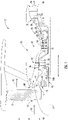
- FIG. 4 an axial cross sectional view of the shaft assembly 95 is generally provided.
- FIG. 5 a perspective view of the spacer 150 of the shaft assembly 95 is generally provided.
- the spacer 150 defines a first portion 151 extended inward in the radial direction R and a second portion 152 extended in the axial direction A.
- the first portion 151 is disposed in the groove 104 of the coupling shaft 100.
- the spacer 150 may further define one or more splits 155 along a circumference 156 of the spacer 150. In one embodiment, as shown in FIG.
- the spacer 150 defines one split 155 such that the spacer 150 may flex, bend, or otherwise translate outwardly along the radial direction R.
- the spacer 150 defines a plurality of splits 155 such that the spacer 150 may include a plurality of sections 157 joined together to collectively form the circumference 156 placed into the groove 104 of the coupling shaft 100.
- the sleeve 200 extends along the axial direction A adjacent to the coupling shaft 100.
- the sleeve 200 defines a threaded portion 202 including a plurality of sleeve threads 204 defined outwardly in the radial direction R.
- the threaded portion 202 extends along the axial direction A.
- the sleeve 200 is disposed outward of the spacer 150 in the radial direction R.
- the sleeve 200 defines the star gear 52 of the gearbox assembly 45.
- the nut 250 defines a plurality of nut threads 252 defined inwardly in the radial direction R such that the plurality of nut threads 252 may mate or thread into the plurality of sleeve threads 204.
- the plurality of threads 204, 252 may define a coarse thread or a fine thread.
- the nut 250 further defines a radial portion 254 extended inward in the radial direction R.
- the radial portion 254 is adjacent to at least a portion of the sleeve 200 and at least a portion of the spacer 150 in the axial direction A.
- the nut 250 may further define a nut groove 256 along the circumferential direction C, into which a lock washer 260 may be disposed between the nut 250 and the sleeve 200 in the radial direction R.
- the lock washer 260 may further aid retention of the nut 250 to the sleeve 200.
- the shaft assembly 95 may define the coupling shaft 100, the spacer 150, the sleeve 200, and the nut 250 in adjacent arrangement in the radial direction R.
- the shaft assembly 95 may further define the first portion 151 of the spacer 150 toward a first end 97 of the shaft assembly 95 (e.g. the forward end 99) and the radial portion 254 of the nut 250 toward a second end 96 of the shaft assembly 95 (e.g. the aft end 98).
- the aforementioned arrangements may altogether provide retention of the sleeve 200 along the axial direction A toward the forward end 99 and the aft end 98. For example, as shown in FIG.
- the aforementioned combination may enable the sleeve 200 to be retained with relatively large forces onto the spacer 150 while applying relatively small forces onto the coupling shaft 100.
- the spacer 150 may further define a surface 153 including a first material.
- the first material includes an elastic material.
- the elastic material may include metals or composites defining generally elastic properties.
- the first material may include a composite 154 applied onto or within the surface 153 of the spacer 150.
- the composite 154 is a polymer matrix composite.
- the composite 154 may be applied within 159 the surface 153 of the spacer 150.
- the composite 154 may be formed from a solid foamed synthetic polymer.
- the solid foamed synthetic polymer may include a synthetic elastomer, such as an elastomeric polyurethane.
- the solid foamed synthetic polymer may include an ethylene vinyl acetate and/or an olefin polymer.
- the composite 154 is formed from a plurality of fabric sheets formed from a plurality of fibers.
- the plurality of fibers may form a network of fibers (e.g., a woven network, a random or parallel nonwoven network, or another orientation).
- the composite 154 may be constructed from high strength and high modulus fibers, such as para-aramid synthetic fibers (e.g., KEVLAR fibers available from E.I. duPont de Nemours and Company), metal fibers, ceramic fibers, glass fibers, carbon fibers, boron fibers, p-phenylenetherephtalamide fibers, aromatic polyamide fibers, silicon carbide fibers, graphite fibers, nylon fibers, or mixtures thereof.
- suitable fibers includes ultra-high molecular weight polyethylene (e.g., SPECTRA fibers manufactured by Honeywell International Inc.).
- the sleeve 200 may further define a surface extended along the axial direction A onto which a bearing assembly 201 is applied.
- the shaft assembly 95 shown in FIG. 7 may be configured substantially similarly as those shown and described in regard to FIGS. 1-5 .
- the sleeve 200 and the bearing assembly 201 may be at least partially integrally formed such that the sleeve 200 and the bearing assembly 201 together install onto the coupling shaft 100.
- the bearing assembly 201 defines a roller bearing.
- a volume of air as indicated schematically by arrows 90 enters the engine 10.
- a portion of the air as indicated schematically by arrows 91 is directed or routed outside of the engine core 20 to provide propulsion.
- another portion of air as indicated schematically by arrows 92 is directed or routed through an associated inlet 80 into the compressor section 21.
- the air 92 is progressively compressed as it flows through the compressor section 21, such as through the LPC 22 and the HPC 24, toward the combustion section 26.
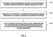
- affixing the threaded nut onto the threaded sleeve includes applying a desired amount of torque to the threaded nut, the threaded sleeve, and/or the spacer. In another embodiment, affixing the threaded nut may include applying an amount of torque limited by the spacer, the threaded sleeve, and/or the threaded nut.
Landscapes
- Engineering & Computer Science (AREA)
- General Engineering & Computer Science (AREA)
- Mechanical Engineering (AREA)
- Chemical & Material Sciences (AREA)
- Combustion & Propulsion (AREA)
- Turbine Rotor Nozzle Sealing (AREA)
- Structures Of Non-Positive Displacement Pumps (AREA)
- Shafts, Cranks, Connecting Bars, And Related Bearings (AREA)
Claims (13)
- Wellenanordnung (95) für ein Turbinentriebwerk (10), wobei das Turbinentriebwerk (10) eine axiale Richtung und eine radiale Richtung definiert, wobei das Turbinentriebwerk (10) eine Fan- oder Propelleranordnung (14) und einen Triebwerkskern (20) beinhaltet und ferner wobei die Fan- oder Propelleranordnung (14) ein Getriebe (45) beinhaltet, wobei die Wellenanordnung (95) Folgendes umfasst:eine Kopplungswelle (100), die konfiguriert ist, um an einem ersten Ende (97) mit dem Triebwerkskern (20) verbunden zu werden, und ferner konfiguriert ist, um an einem zweiten Ende (96) mit dem Getriebe (45) gekoppelt zu werden, wobei die Kopplungswelle (100) eine ringförmige Oberfläche (103) definiert, die sich entlang der axialen Richtung erstreckt, und wobei die Oberfläche eine Nut (104) definiert, die sich in einer Umfangsrichtung erstreckt;einen Abstandshalter (150), wobei der Abstandshalter (150) einen ersten Abschnitt (151), der sich in die radiale Richtung nach innen erstreckt, und einen zweiten Abschnitt (152) definiert, der sich in die axiale Richtung erstreckt, und wobei der erste Abschnitt (151) in der Nut (104) der Kopplungswelle (100) eingerichtet ist; wobei ein erster Abschnitt (151) des Abstandshalters (150) zu dem ersten Ende (97) der Wellenanordnung (95) hin definiert ist;eine Hülse (200), wobei die Hülse (200) einen Gewindeabschnitt (202) definiert, der mehrere Hülsengewinde (204) umfasst, die in der radialen Richtung nach außen definiert sind, wobei sich der Gewindeabschnitt (202) entlang der axialen Richtung erstreckt, und wobei die Hülse (200) nach außen von dem Abstandshalter (150) in der radialen Richtung eingerichtet ist; wobei ein Abschnitt (206) der Hülse (200) an den ersten Abschnitt (151) des Abstandshalters (150) in der axialen Richtung anstößt; undeine Mutter (250), wobei die Mutter (250) mehrere Muttergewinde (252) definiert, die in der radialen Richtung nach innen definiert sind, und wobei die mehreren Muttergewinde (252) der Mutter (250) konfiguriert sind, um mit den mehreren Hülsengewinden (204) der Hülse (200) zusammengepasst zu werden, und ferner wobei die Mutter (250) einen radialen Abschnitt (254) definiert, der sich in der radialen Richtung nach innen und zu dem zweiten Ende (96) der Wellenanordnung (95) hin erstreckt, und wobei der radiale Abschnitt (254) an wenigstens einen Abschnitt der Hülse (200) und wenigstens einen Abschnitt des Abstandshalters (150) in der axialen Richtung angrenzt, und wobei der radiale Abschnitt (254) an wenigstens einen Abschnitt des Abstandshalters (150) in der axialen Richtung in einem angeordneten Zustand anstößt;wobei die Kopplungswelle (100), der Abstandshalter (150), die Hülse (200) und die Mutter (250) entlang der radialen Richtung in einer angrenzenden Disposition sind.
- Wellenanordnung (95) nach Anspruch 1, wobei die Hülse (200) ein Sterngetriebe (52) für das Getriebe (45) definiert.
- Wellenanordnung (95) nach einem der Ansprüche 1 bis 2, wobei der Abstandshalter (150) ferner eine Teilung (155) entlang einem Umfang (156) des Abstandshalters (150) definiert.
- Wellenanordnung (95) nach einem der Ansprüche 1 bis 3, wobei der Abstandshalter (150) einen oder mehrere Bereiche (157) definiert, die gemeinsam einen Umfang (156) des Abstandshalters (150) ausbilden.
- Wellenanordnung (95) nach einem der Ansprüche 1 bis 4, wobei der Abstandshalter (150) ein erstes Material definiert, wobei das erste Material ein elastisches Material umfasst.
- Wellenanordnung (95) nach einem der Ansprüche 1 bis 5, wobei der Abstandshalter (150) ein erstes Material definiert, wobei das erste Material einen Polymermatrixverbundstoff (154) umfasst.
- Wellenanordnung (95) nach Anspruch 6, wobei das erste Material eine feste geschäumte synthetische Polymermatrix umfasst.
- Wellenanordnung (95) nach Anspruch 7, wobei die feste geschäumte synthetische Polymermatrix ein synthetisches Elastomer ist.
- Wellenanordnung (95) nach einem der Ansprüche 1 bis 8, wobei der Abstandshalter (150) ein erstes Material definiert und wobei das erste Material mehrere Gewebelagen umfasst, wobei jede Gewebelage ein Netzwerk von Fasern umfasst.
- Wellenanordnung (95) nach einem der Ansprüche 1 bis 9, die ferner Folgendes umfasst:
ein Federring (260), der innerhalb einer Mutternut (256) eingerichtet ist, die in der Mutter (250) entlang der Umfangsrichtung definiert ist, wobei der Federring (260) zwischen der Mutter (250) und der Hülse (200) entlang der radialen Richtung eingerichtet ist. - Wellenanordnung (95) nach einem der Ansprüche 1 oder 3 bis 10, wobei die Hülse (200) eine Lageranordnung (201) definiert.
- Verfahren zum Halten einer Gewindehülse (200) einer Wellenanordnung (95) für ein Turbinentriebwerk, wobei die Wellenanordnung (95) eine Wellenanordnung (95) nach Anspruch 1 ist, wobei das Verfahren Folgendes umfasst:Positionieren des Abstandshalters (150) in der Nut (104) der Welle derart, dass sich der axial erstreckte zweite Abschnitt (152) im Allgemeinen parallel zu der Welle erstreckt;Positionieren wenigstens eines Abschnitts der Gewindehülse (200) in der radial angrenzenden Disposition zu dem axial erstreckten zweiten Abschnitt (152) des Abstandshalters (150); undBefestigen der Gewindemutter (250) auf der Gewindehülse (200), wobei das Befestigen der Gewindemutter (250) auf die Gewindehülse (200) die Welle, den Abstandshalter (150), die Gewindehülse (200) und die Gewindemutter (250) in der radial angrenzenden Disposition positioniert.
- Verfahren nach Anspruch 12, wobei das Befestigen der Gewindemutter (250) auf der Gewindehülse (200) ein Aufbringen einer gewünschten Menge an Drehmoment auf die Gewindemutter (250) und/oder die Gewindehülse (200) beinhaltet.
Priority Applications (6)
| Application Number | Priority Date | Filing Date | Title |
|---|---|---|---|
| EP17425011.8A EP3354883B1 (de) | 2017-01-30 | 2017-01-30 | Sicherungsmutter eines sonnenrads für einen gasturbinenmotor |
| US16/482,024 US11199138B2 (en) | 2017-01-30 | 2018-01-24 | Locknut sun gear for gas turbine engine |
| PCT/EP2018/051737 WO2018138154A1 (en) | 2017-01-30 | 2018-01-24 | Locknut sun gear for gas turbine engine |
| CA3050324A CA3050324A1 (en) | 2017-01-30 | 2018-01-24 | Locknut sun gear for gas turbine engine |
| JP2019541147A JP2020506324A (ja) | 2017-01-30 | 2018-01-24 | ガスタービンエンジンのためのロックナット太陽歯車 |
| CN201880009001.9A CN110234858B (zh) | 2017-01-30 | 2018-01-24 | 用于燃气涡轮发动机的锁紧螺母太阳齿轮 |
Applications Claiming Priority (1)
| Application Number | Priority Date | Filing Date | Title |
|---|---|---|---|
| EP17425011.8A EP3354883B1 (de) | 2017-01-30 | 2017-01-30 | Sicherungsmutter eines sonnenrads für einen gasturbinenmotor |
Publications (2)
| Publication Number | Publication Date |
|---|---|
| EP3354883A1 EP3354883A1 (de) | 2018-08-01 |
| EP3354883B1 true EP3354883B1 (de) | 2022-04-20 |
Family
ID=58266540
Family Applications (1)
| Application Number | Title | Priority Date | Filing Date |
|---|---|---|---|
| EP17425011.8A Active EP3354883B1 (de) | 2017-01-30 | 2017-01-30 | Sicherungsmutter eines sonnenrads für einen gasturbinenmotor |
Country Status (6)
| Country | Link |
|---|---|
| US (1) | US11199138B2 (de) |
| EP (1) | EP3354883B1 (de) |
| JP (1) | JP2020506324A (de) |
| CN (1) | CN110234858B (de) |
| CA (1) | CA3050324A1 (de) |
| WO (1) | WO2018138154A1 (de) |
Cited By (1)
| Publication number | Priority date | Publication date | Assignee | Title |
|---|---|---|---|---|
| FR3140918A1 (fr) * | 2022-10-12 | 2024-04-19 | Safran Aircraft Engines | Roulement pour le guidage en rotation d’un arbre de turbomachine d’aeronef, presentant des moyens facilitant son extraction de l’arbre |
Families Citing this family (7)
| Publication number | Priority date | Publication date | Assignee | Title |
|---|---|---|---|---|
| US11078951B2 (en) | 2019-05-20 | 2021-08-03 | Hamilton Sundstrand Corporation | Locking assembly for rotatable components |
| EP3913250B1 (de) * | 2020-05-21 | 2023-06-28 | Hamilton Sundstrand Corporation | Generatorwellenanordnung |
| CN113513410B (zh) * | 2021-05-27 | 2022-06-07 | 中国航发南方工业有限公司 | 一种用于航空发动机的可调防松连接结构 |
| IT202100018935A1 (it) | 2021-07-16 | 2023-01-16 | Ge Avio Srl | Sistema smorzatore per un albero di un motore |
| US12018724B2 (en) * | 2022-02-23 | 2024-06-25 | Textron Innovations Inc. | Bearing-raceway systems and methods |
| CN115559817B (zh) * | 2022-12-01 | 2023-03-21 | 成都中科翼能科技有限公司 | 一种燃气轮机的液压起动装置的双支撑安装架结构 |
| CN119062445B (zh) * | 2024-11-01 | 2025-01-24 | 成都中科翼能科技有限公司 | 一种燃气轮机低压转子的自锁紧结构 |
Family Cites Families (9)
| Publication number | Priority date | Publication date | Assignee | Title |
|---|---|---|---|---|
| US4159888A (en) * | 1977-10-07 | 1979-07-03 | General Motors Corporation | Thrust balancing |
| US4456425A (en) * | 1980-11-20 | 1984-06-26 | General Electric Company | Modular inlet gearbox for a gas turbine engine |
| FR2857708B1 (fr) * | 2003-07-15 | 2005-09-23 | Snecma Moteurs | Dispositif perfectionne de fixation d'un arbre de moteur sur un support de palier |
| FR2896827B1 (fr) * | 2006-01-27 | 2008-04-25 | Snecma Sa | Assemblage a encombrement radial reduit entre un arbre de turbine et un tourillon d'arbre de compresseur de turbomachine |
| US7882693B2 (en) * | 2006-11-29 | 2011-02-08 | General Electric Company | Turbofan engine assembly and method of assembling same |
| WO2013141926A1 (en) * | 2011-12-30 | 2013-09-26 | United Technologies Corporation | Gas turbine engine oil buffering |
| RU2572744C1 (ru) * | 2014-10-14 | 2016-01-20 | Открытое акционерное общество "Авиадвигатель" | Двухконтурный газотурбинный двигатель |
| EP3176407B1 (de) | 2014-11-14 | 2019-05-15 | IHI Corporation | Triebwerk |
| DE102016013076A1 (de) * | 2016-11-04 | 2018-05-09 | Neumayer Tekfor Engineering Gmbh | Verbindungsanordnung zum Verbinden einer Welle mit einem Bauteil |
-
2017
- 2017-01-30 EP EP17425011.8A patent/EP3354883B1/de active Active
-
2018
- 2018-01-24 CA CA3050324A patent/CA3050324A1/en not_active Abandoned
- 2018-01-24 US US16/482,024 patent/US11199138B2/en active Active
- 2018-01-24 WO PCT/EP2018/051737 patent/WO2018138154A1/en not_active Ceased
- 2018-01-24 CN CN201880009001.9A patent/CN110234858B/zh active Active
- 2018-01-24 JP JP2019541147A patent/JP2020506324A/ja active Pending
Cited By (1)
| Publication number | Priority date | Publication date | Assignee | Title |
|---|---|---|---|---|
| FR3140918A1 (fr) * | 2022-10-12 | 2024-04-19 | Safran Aircraft Engines | Roulement pour le guidage en rotation d’un arbre de turbomachine d’aeronef, presentant des moyens facilitant son extraction de l’arbre |
Also Published As
| Publication number | Publication date |
|---|---|
| JP2020506324A (ja) | 2020-02-27 |
| CN110234858B (zh) | 2022-04-12 |
| CA3050324A1 (en) | 2018-08-02 |
| US20190390604A1 (en) | 2019-12-26 |
| CN110234858A (zh) | 2019-09-13 |
| EP3354883A1 (de) | 2018-08-01 |
| US11199138B2 (en) | 2021-12-14 |
| WO2018138154A1 (en) | 2018-08-02 |
Similar Documents
| Publication | Publication Date | Title |
|---|---|---|
| EP3354883B1 (de) | Sicherungsmutter eines sonnenrads für einen gasturbinenmotor | |
| US11898518B2 (en) | Aircraft and direct drive engine under wing installation | |
| US10914240B2 (en) | Gas turbine | |
| EP2565424B1 (de) | Drehmomentrahmen und asymmetrisches Gleitlager für ein Fangetriebesystem | |
| US11391326B2 (en) | Flexible coupling shaft for turbine engine | |
| EP3270009B1 (de) | Gasturbine mit getriebe | |
| EP3267075B1 (de) | Gasturbine mit getriebe | |
| EP3354882B1 (de) | Verfahren und system zur verbindung eines turbinenmotorgetriebes an einen motorkern | |
| US11982201B2 (en) | Damper system for an engine shaft | |
| US10654577B2 (en) | Rainbow flowpath low pressure turbine rotor assembly | |
| EP3546726B1 (de) | Turbofantriebwerkmontageverfahren | |
| US11131209B2 (en) | Gas turbine | |
| EP3587764A1 (de) | Gasturbine | |
| US20180237120A1 (en) | Aircraft with Under Wing Direct Drive Low Pressure Turbine | |
| US8967977B2 (en) | Locked spacer for a gas turbine engine shaft | |
| US12497908B2 (en) | Turbine engine including a fan assembly having a damper |
Legal Events
| Date | Code | Title | Description |
|---|---|---|---|
| PUAI | Public reference made under article 153(3) epc to a published international application that has entered the european phase |
Free format text: ORIGINAL CODE: 0009012 |
|
| STAA | Information on the status of an ep patent application or granted ep patent |
Free format text: STATUS: THE APPLICATION HAS BEEN PUBLISHED |
|
| AK | Designated contracting states |
Kind code of ref document: A1 Designated state(s): AL AT BE BG CH CY CZ DE DK EE ES FI FR GB GR HR HU IE IS IT LI LT LU LV MC MK MT NL NO PL PT RO RS SE SI SK SM TR |
|
| AX | Request for extension of the european patent |
Extension state: BA ME |
|
| STAA | Information on the status of an ep patent application or granted ep patent |
Free format text: STATUS: REQUEST FOR EXAMINATION WAS MADE |
|
| 17P | Request for examination filed |
Effective date: 20190201 |
|
| RBV | Designated contracting states (corrected) |
Designated state(s): AL AT BE BG CH CY CZ DE DK EE ES FI FR GB GR HR HU IE IS IT LI LT LU LV MC MK MT NL NO PL PT RO RS SE SI SK SM TR |
|
| STAA | Information on the status of an ep patent application or granted ep patent |
Free format text: STATUS: EXAMINATION IS IN PROGRESS |
|
| 17Q | First examination report despatched |
Effective date: 20190709 |
|
| GRAP | Despatch of communication of intention to grant a patent |
Free format text: ORIGINAL CODE: EPIDOSNIGR1 |
|
| STAA | Information on the status of an ep patent application or granted ep patent |
Free format text: STATUS: GRANT OF PATENT IS INTENDED |
|
| INTG | Intention to grant announced |
Effective date: 20211116 |
|
| RAP3 | Party data changed (applicant data changed or rights of an application transferred) |
Owner name: GE AVIO S.R.L. |
|
| GRAS | Grant fee paid |
Free format text: ORIGINAL CODE: EPIDOSNIGR3 |
|
| GRAA | (expected) grant |
Free format text: ORIGINAL CODE: 0009210 |
|
| STAA | Information on the status of an ep patent application or granted ep patent |
Free format text: STATUS: THE PATENT HAS BEEN GRANTED |
|
| AK | Designated contracting states |
Kind code of ref document: B1 Designated state(s): AL AT BE BG CH CY CZ DE DK EE ES FI FR GB GR HR HU IE IS IT LI LT LU LV MC MK MT NL NO PL PT RO RS SE SI SK SM TR |
|
| REG | Reference to a national code |
Ref country code: GB Ref legal event code: FG4D |
|
| REG | Reference to a national code |
Ref country code: CH Ref legal event code: EP |
|
| REG | Reference to a national code |
Ref country code: IE Ref legal event code: FG4D |
|
| REG | Reference to a national code |
Ref country code: DE Ref legal event code: R096 Ref document number: 602017056200 Country of ref document: DE |
|
| REG | Reference to a national code |
Ref country code: AT Ref legal event code: REF Ref document number: 1485319 Country of ref document: AT Kind code of ref document: T Effective date: 20220515 |
|
| REG | Reference to a national code |
Ref country code: LT Ref legal event code: MG9D |
|
| REG | Reference to a national code |
Ref country code: NL Ref legal event code: MP Effective date: 20220420 |
|
| REG | Reference to a national code |
Ref country code: AT Ref legal event code: MK05 Ref document number: 1485319 Country of ref document: AT Kind code of ref document: T Effective date: 20220420 |
|
| PG25 | Lapsed in a contracting state [announced via postgrant information from national office to epo] |
Ref country code: NL Free format text: LAPSE BECAUSE OF FAILURE TO SUBMIT A TRANSLATION OF THE DESCRIPTION OR TO PAY THE FEE WITHIN THE PRESCRIBED TIME-LIMIT Effective date: 20220420 |
|
| PG25 | Lapsed in a contracting state [announced via postgrant information from national office to epo] |
Ref country code: SE Free format text: LAPSE BECAUSE OF FAILURE TO SUBMIT A TRANSLATION OF THE DESCRIPTION OR TO PAY THE FEE WITHIN THE PRESCRIBED TIME-LIMIT Effective date: 20220420 Ref country code: PT Free format text: LAPSE BECAUSE OF FAILURE TO SUBMIT A TRANSLATION OF THE DESCRIPTION OR TO PAY THE FEE WITHIN THE PRESCRIBED TIME-LIMIT Effective date: 20220822 Ref country code: NO Free format text: LAPSE BECAUSE OF FAILURE TO SUBMIT A TRANSLATION OF THE DESCRIPTION OR TO PAY THE FEE WITHIN THE PRESCRIBED TIME-LIMIT Effective date: 20220720 Ref country code: LT Free format text: LAPSE BECAUSE OF FAILURE TO SUBMIT A TRANSLATION OF THE DESCRIPTION OR TO PAY THE FEE WITHIN THE PRESCRIBED TIME-LIMIT Effective date: 20220420 Ref country code: HR Free format text: LAPSE BECAUSE OF FAILURE TO SUBMIT A TRANSLATION OF THE DESCRIPTION OR TO PAY THE FEE WITHIN THE PRESCRIBED TIME-LIMIT Effective date: 20220420 Ref country code: GR Free format text: LAPSE BECAUSE OF FAILURE TO SUBMIT A TRANSLATION OF THE DESCRIPTION OR TO PAY THE FEE WITHIN THE PRESCRIBED TIME-LIMIT Effective date: 20220721 Ref country code: FI Free format text: LAPSE BECAUSE OF FAILURE TO SUBMIT A TRANSLATION OF THE DESCRIPTION OR TO PAY THE FEE WITHIN THE PRESCRIBED TIME-LIMIT Effective date: 20220420 Ref country code: ES Free format text: LAPSE BECAUSE OF FAILURE TO SUBMIT A TRANSLATION OF THE DESCRIPTION OR TO PAY THE FEE WITHIN THE PRESCRIBED TIME-LIMIT Effective date: 20220420 Ref country code: BG Free format text: LAPSE BECAUSE OF FAILURE TO SUBMIT A TRANSLATION OF THE DESCRIPTION OR TO PAY THE FEE WITHIN THE PRESCRIBED TIME-LIMIT Effective date: 20220720 Ref country code: AT Free format text: LAPSE BECAUSE OF FAILURE TO SUBMIT A TRANSLATION OF THE DESCRIPTION OR TO PAY THE FEE WITHIN THE PRESCRIBED TIME-LIMIT Effective date: 20220420 |
|
| PG25 | Lapsed in a contracting state [announced via postgrant information from national office to epo] |
Ref country code: RS Free format text: LAPSE BECAUSE OF FAILURE TO SUBMIT A TRANSLATION OF THE DESCRIPTION OR TO PAY THE FEE WITHIN THE PRESCRIBED TIME-LIMIT Effective date: 20220420 Ref country code: PL Free format text: LAPSE BECAUSE OF FAILURE TO SUBMIT A TRANSLATION OF THE DESCRIPTION OR TO PAY THE FEE WITHIN THE PRESCRIBED TIME-LIMIT Effective date: 20220420 Ref country code: LV Free format text: LAPSE BECAUSE OF FAILURE TO SUBMIT A TRANSLATION OF THE DESCRIPTION OR TO PAY THE FEE WITHIN THE PRESCRIBED TIME-LIMIT Effective date: 20220420 Ref country code: IS Free format text: LAPSE BECAUSE OF FAILURE TO SUBMIT A TRANSLATION OF THE DESCRIPTION OR TO PAY THE FEE WITHIN THE PRESCRIBED TIME-LIMIT Effective date: 20220820 |
|
| REG | Reference to a national code |
Ref country code: DE Ref legal event code: R097 Ref document number: 602017056200 Country of ref document: DE |
|
| PG25 | Lapsed in a contracting state [announced via postgrant information from national office to epo] |
Ref country code: SM Free format text: LAPSE BECAUSE OF FAILURE TO SUBMIT A TRANSLATION OF THE DESCRIPTION OR TO PAY THE FEE WITHIN THE PRESCRIBED TIME-LIMIT Effective date: 20220420 Ref country code: SK Free format text: LAPSE BECAUSE OF FAILURE TO SUBMIT A TRANSLATION OF THE DESCRIPTION OR TO PAY THE FEE WITHIN THE PRESCRIBED TIME-LIMIT Effective date: 20220420 Ref country code: RO Free format text: LAPSE BECAUSE OF FAILURE TO SUBMIT A TRANSLATION OF THE DESCRIPTION OR TO PAY THE FEE WITHIN THE PRESCRIBED TIME-LIMIT Effective date: 20220420 Ref country code: EE Free format text: LAPSE BECAUSE OF FAILURE TO SUBMIT A TRANSLATION OF THE DESCRIPTION OR TO PAY THE FEE WITHIN THE PRESCRIBED TIME-LIMIT Effective date: 20220420 Ref country code: DK Free format text: LAPSE BECAUSE OF FAILURE TO SUBMIT A TRANSLATION OF THE DESCRIPTION OR TO PAY THE FEE WITHIN THE PRESCRIBED TIME-LIMIT Effective date: 20220420 Ref country code: CZ Free format text: LAPSE BECAUSE OF FAILURE TO SUBMIT A TRANSLATION OF THE DESCRIPTION OR TO PAY THE FEE WITHIN THE PRESCRIBED TIME-LIMIT Effective date: 20220420 |
|
| PLBE | No opposition filed within time limit |
Free format text: ORIGINAL CODE: 0009261 |
|
| STAA | Information on the status of an ep patent application or granted ep patent |
Free format text: STATUS: NO OPPOSITION FILED WITHIN TIME LIMIT |
|
| 26N | No opposition filed |
Effective date: 20230123 |
|
| PG25 | Lapsed in a contracting state [announced via postgrant information from national office to epo] |
Ref country code: AL Free format text: LAPSE BECAUSE OF FAILURE TO SUBMIT A TRANSLATION OF THE DESCRIPTION OR TO PAY THE FEE WITHIN THE PRESCRIBED TIME-LIMIT Effective date: 20220420 |
|
| PG25 | Lapsed in a contracting state [announced via postgrant information from national office to epo] |
Ref country code: SI Free format text: LAPSE BECAUSE OF FAILURE TO SUBMIT A TRANSLATION OF THE DESCRIPTION OR TO PAY THE FEE WITHIN THE PRESCRIBED TIME-LIMIT Effective date: 20220420 |
|
| P01 | Opt-out of the competence of the unified patent court (upc) registered |
Effective date: 20230414 |
|
| REG | Reference to a national code |
Ref country code: CH Ref legal event code: PL |
|
| PG25 | Lapsed in a contracting state [announced via postgrant information from national office to epo] |
Ref country code: LU Free format text: LAPSE BECAUSE OF NON-PAYMENT OF DUE FEES Effective date: 20230130 |
|
| REG | Reference to a national code |
Ref country code: BE Ref legal event code: MM Effective date: 20230131 |
|
| PG25 | Lapsed in a contracting state [announced via postgrant information from national office to epo] |
Ref country code: LI Free format text: LAPSE BECAUSE OF NON-PAYMENT OF DUE FEES Effective date: 20230131 Ref country code: CH Free format text: LAPSE BECAUSE OF NON-PAYMENT OF DUE FEES Effective date: 20230131 |
|
| PG25 | Lapsed in a contracting state [announced via postgrant information from national office to epo] |
Ref country code: BE Free format text: LAPSE BECAUSE OF NON-PAYMENT OF DUE FEES Effective date: 20230131 |
|
| PG25 | Lapsed in a contracting state [announced via postgrant information from national office to epo] |
Ref country code: IT Free format text: LAPSE BECAUSE OF FAILURE TO SUBMIT A TRANSLATION OF THE DESCRIPTION OR TO PAY THE FEE WITHIN THE PRESCRIBED TIME-LIMIT Effective date: 20220420 Ref country code: IE Free format text: LAPSE BECAUSE OF NON-PAYMENT OF DUE FEES Effective date: 20230130 |
|
| PG25 | Lapsed in a contracting state [announced via postgrant information from national office to epo] |
Ref country code: MC Free format text: LAPSE BECAUSE OF FAILURE TO SUBMIT A TRANSLATION OF THE DESCRIPTION OR TO PAY THE FEE WITHIN THE PRESCRIBED TIME-LIMIT Effective date: 20220420 |
|
| PG25 | Lapsed in a contracting state [announced via postgrant information from national office to epo] |
Ref country code: MC Free format text: LAPSE BECAUSE OF FAILURE TO SUBMIT A TRANSLATION OF THE DESCRIPTION OR TO PAY THE FEE WITHIN THE PRESCRIBED TIME-LIMIT Effective date: 20220420 |
|
| PG25 | Lapsed in a contracting state [announced via postgrant information from national office to epo] |
Ref country code: BG Free format text: LAPSE BECAUSE OF FAILURE TO SUBMIT A TRANSLATION OF THE DESCRIPTION OR TO PAY THE FEE WITHIN THE PRESCRIBED TIME-LIMIT Effective date: 20220420 |
|
| PG25 | Lapsed in a contracting state [announced via postgrant information from national office to epo] |
Ref country code: BG Free format text: LAPSE BECAUSE OF FAILURE TO SUBMIT A TRANSLATION OF THE DESCRIPTION OR TO PAY THE FEE WITHIN THE PRESCRIBED TIME-LIMIT Effective date: 20220420 |
|
| PG25 | Lapsed in a contracting state [announced via postgrant information from national office to epo] |
Ref country code: CY Free format text: LAPSE BECAUSE OF FAILURE TO SUBMIT A TRANSLATION OF THE DESCRIPTION OR TO PAY THE FEE WITHIN THE PRESCRIBED TIME-LIMIT; INVALID AB INITIO Effective date: 20170130 |
|
| PG25 | Lapsed in a contracting state [announced via postgrant information from national office to epo] |
Ref country code: HU Free format text: LAPSE BECAUSE OF FAILURE TO SUBMIT A TRANSLATION OF THE DESCRIPTION OR TO PAY THE FEE WITHIN THE PRESCRIBED TIME-LIMIT; INVALID AB INITIO Effective date: 20170130 |
|
| PG25 | Lapsed in a contracting state [announced via postgrant information from national office to epo] |
Ref country code: TR Free format text: LAPSE BECAUSE OF FAILURE TO SUBMIT A TRANSLATION OF THE DESCRIPTION OR TO PAY THE FEE WITHIN THE PRESCRIBED TIME-LIMIT Effective date: 20220420 |
|
| PGFP | Annual fee paid to national office [announced via postgrant information from national office to epo] |
Ref country code: GB Payment date: 20251220 Year of fee payment: 10 |
|
| PGFP | Annual fee paid to national office [announced via postgrant information from national office to epo] |
Ref country code: FR Payment date: 20251217 Year of fee payment: 10 |
|
| PGFP | Annual fee paid to national office [announced via postgrant information from national office to epo] |
Ref country code: DE Payment date: 20251217 Year of fee payment: 10 |