EP3354917A2 - Accouplement denté du raccordement arbre-moyeu et procédé de fabrication d'un raccordement arbre-moyeu - Google Patents
Accouplement denté du raccordement arbre-moyeu et procédé de fabrication d'un raccordement arbre-moyeu Download PDFInfo
- Publication number
- EP3354917A2 EP3354917A2 EP17206533.6A EP17206533A EP3354917A2 EP 3354917 A2 EP3354917 A2 EP 3354917A2 EP 17206533 A EP17206533 A EP 17206533A EP 3354917 A2 EP3354917 A2 EP 3354917A2
- Authority
- EP
- European Patent Office
- Prior art keywords
- driver element
- radial
- tooth elements
- shaft
- connector
- Prior art date
- Legal status (The legal status is an assumption and is not a legal conclusion. Google has not performed a legal analysis and makes no representation as to the accuracy of the status listed.)
- Granted
Links
Images


Classifications
-
- F—MECHANICAL ENGINEERING; LIGHTING; HEATING; WEAPONS; BLASTING
- F16—ENGINEERING ELEMENTS AND UNITS; GENERAL MEASURES FOR PRODUCING AND MAINTAINING EFFECTIVE FUNCTIONING OF MACHINES OR INSTALLATIONS; THERMAL INSULATION IN GENERAL
- F16D—COUPLINGS FOR TRANSMITTING ROTATION; CLUTCHES; BRAKES
- F16D1/00—Couplings for rigidly connecting two coaxial shafts or other movable machine elements
- F16D1/06—Couplings for rigidly connecting two coaxial shafts or other movable machine elements for attachment of a member on a shaft or on a shaft-end
-
- B—PERFORMING OPERATIONS; TRANSPORTING
- B23—MACHINE TOOLS; METAL-WORKING NOT OTHERWISE PROVIDED FOR
- B23F—MAKING GEARS OR TOOTHED RACKS
- B23F17/00—Special methods or machines for making gear teeth, not covered by the preceding groups
- B23F17/006—Special methods or machines for making gear teeth, not covered by the preceding groups using different machines or machining operations
-
- B—PERFORMING OPERATIONS; TRANSPORTING
- B23—MACHINE TOOLS; METAL-WORKING NOT OTHERWISE PROVIDED FOR
- B23P—METAL-WORKING NOT OTHERWISE PROVIDED FOR; COMBINED OPERATIONS; UNIVERSAL MACHINE TOOLS
- B23P15/00—Making specific metal objects by operations not covered by a single other subclass or a group in this subclass
- B23P15/14—Making specific metal objects by operations not covered by a single other subclass or a group in this subclass gear parts, e.g. gear wheels
-
- F—MECHANICAL ENGINEERING; LIGHTING; HEATING; WEAPONS; BLASTING
- F16—ENGINEERING ELEMENTS AND UNITS; GENERAL MEASURES FOR PRODUCING AND MAINTAINING EFFECTIVE FUNCTIONING OF MACHINES OR INSTALLATIONS; THERMAL INSULATION IN GENERAL
- F16D—COUPLINGS FOR TRANSMITTING ROTATION; CLUTCHES; BRAKES
- F16D1/00—Couplings for rigidly connecting two coaxial shafts or other movable machine elements
- F16D1/10—Quick-acting couplings in which the parts are connected by simply bringing them together axially
- F16D1/104—Quick-acting couplings in which the parts are connected by simply bringing them together axially having retaining means rotating with the coupling and acting only by friction
-
- F—MECHANICAL ENGINEERING; LIGHTING; HEATING; WEAPONS; BLASTING
- F16—ENGINEERING ELEMENTS AND UNITS; GENERAL MEASURES FOR PRODUCING AND MAINTAINING EFFECTIVE FUNCTIONING OF MACHINES OR INSTALLATIONS; THERMAL INSULATION IN GENERAL
- F16D—COUPLINGS FOR TRANSMITTING ROTATION; CLUTCHES; BRAKES
- F16D1/00—Couplings for rigidly connecting two coaxial shafts or other movable machine elements
- F16D1/10—Quick-acting couplings in which the parts are connected by simply bringing them together axially
- F16D1/108—Quick-acting couplings in which the parts are connected by simply bringing them together axially having retaining means rotating with the coupling and acting by interengaging parts, i.e. positive coupling
-
- F—MECHANICAL ENGINEERING; LIGHTING; HEATING; WEAPONS; BLASTING
- F16—ENGINEERING ELEMENTS AND UNITS; GENERAL MEASURES FOR PRODUCING AND MAINTAINING EFFECTIVE FUNCTIONING OF MACHINES OR INSTALLATIONS; THERMAL INSULATION IN GENERAL
- F16D—COUPLINGS FOR TRANSMITTING ROTATION; CLUTCHES; BRAKES
- F16D27/00—Magnetically- or electrically- actuated clutches; Control or electric circuits therefor
-
- B—PERFORMING OPERATIONS; TRANSPORTING
- B23—MACHINE TOOLS; METAL-WORKING NOT OTHERWISE PROVIDED FOR
- B23F—MAKING GEARS OR TOOTHED RACKS
- B23F17/00—Special methods or machines for making gear teeth, not covered by the preceding groups
- B23F17/006—Special methods or machines for making gear teeth, not covered by the preceding groups using different machines or machining operations
- B23F17/008—Features relating to transfer of work gears between different work stations
-
- F—MECHANICAL ENGINEERING; LIGHTING; HEATING; WEAPONS; BLASTING
- F16—ENGINEERING ELEMENTS AND UNITS; GENERAL MEASURES FOR PRODUCING AND MAINTAINING EFFECTIVE FUNCTIONING OF MACHINES OR INSTALLATIONS; THERMAL INSULATION IN GENERAL
- F16D—COUPLINGS FOR TRANSMITTING ROTATION; CLUTCHES; BRAKES
- F16D1/00—Couplings for rigidly connecting two coaxial shafts or other movable machine elements
- F16D1/10—Quick-acting couplings in which the parts are connected by simply bringing them together axially
- F16D2001/103—Quick-acting couplings in which the parts are connected by simply bringing them together axially the torque is transmitted via splined connections
-
- F—MECHANICAL ENGINEERING; LIGHTING; HEATING; WEAPONS; BLASTING
- F16—ENGINEERING ELEMENTS AND UNITS; GENERAL MEASURES FOR PRODUCING AND MAINTAINING EFFECTIVE FUNCTIONING OF MACHINES OR INSTALLATIONS; THERMAL INSULATION IN GENERAL
- F16D—COUPLINGS FOR TRANSMITTING ROTATION; CLUTCHES; BRAKES
- F16D27/00—Magnetically- or electrically- actuated clutches; Control or electric circuits therefor
- F16D2027/001—Means for electric connection of the coils of the electromagnetic clutches
Definitions
- the present invention relates to a shaft-hub connector, comprising a first connection part, which a driver element axially displaceable but rotatably associated, wherein the driver element axial tooth elements to form a detachable spur gear teeth with a second connector part, as well as radial tooth elements to form a axially displaceable gearing with the a first coupling part and a toothed coupling and a method for producing a shaft-hub connector.
- Gear couplings have long been known in the art. They are particularly suitable for applications in which they are exposed to high torque and are better suited in such applications than friction clutches. Normally, the gear coupling is engaged at a standstill, or first synchronized with the shaft speed.
- Coupled toothed couplings provide largely torsionally rigid and positive connections. This is achieved by nested outer and inner gears, the prior art in particular uses the DIN 5480-toothing.
- a first connection part has a driver element, with respect to which the first connection part is mounted axially displaceably, but is held in a rotationally fixed manner in each displacement position.
- the entrainment element will abut in the rest position on the first connection part and move due to a triggering force away from this in engagement with a second connection part.
- This engagement is made via a spur gear, which engages only when the driver element has been moved to the second connector part. Even with a maximum engagement of these spur gearing, the gearing between the first connecting part and driving element is retained and the two shaft sections, which are connected via the first and the second connecting part with the toothed coupling, are engaged.
- Such a toothed coupling operates in the prior art with a driver element, which consists of a drive plate on which a toothed ring with internal teeth is mounted.
- a driver element which consists of a drive plate on which a toothed ring with internal teeth is mounted.
- DIN 5480-fitting internal teeth is introduced by collision, so that a one-piece production of the driver element is not possible.
- the assembly of the drive plate and the inner ring gear to an entrainment element is an additional step, on the other hand, the two parts must be made separately as workpieces and thus clamped separately in the lathe and after the basic machining again clamped on the hobbing machine and further processed.
- a corresponding workflow results in the first connection part, which also has to be produced in a processing step on the lathe and a subsequent hobbing operation.
- the invention has the object to provide a shaft-hub connector for producing a gear coupling, such a gear coupling and a manufacturing method for a shaft-hub connector, which avoids these additional costs and thus reducing the manufacturing costs and the production time of a toothed coupling according to the invention.
- a shaft-hub connector which comprises a shaft and a hub, in the present case in the form of a first connection part for connection to a shaft and a driver element as a hub.
- the shaft is assigned a toothed wheel which has radial counter tooth elements to the radial tooth elements of an internal gear rim of the driver element.
- the outer contour of the gear is in this case formed so that it can be fitted accurately into the inner contour of the inner ring gear of the driver element and thus brings ideal conditions for the power transmission.
- a circular arc toothing is realized, which is also known as Wildhaber-Novikov toothing.
- Such teeth are already known in front teeth, but in the present case, such a toothing should be used for the external toothing of the gear, with a radial alignment of the tooth elements use.
- the individual tooth elements have in this case in the axial direction straight edges and surfaces, so that the inner ring gear of the driver element relative to the gear of the shaft is mounted axially displaceable.
- a curing process can be omitted, because due to the low wear in circular arcs such a step is not necessary.
- Such a shaft-hub connector can then be used in a gear coupling as described above.
- the driver element on its side facing away from the first connector part side have a spur gear, with which it can engage in a corresponding spur toothing of a second connector part.
- coaxially arranged connection part up to an engagement in the spur toothing of a coupling process can be effected and thus a toothed coupling can be realized.
- the coupling takes place usually at a standstill of the clutch and shafts, after a rotary synchronization, or at slow speeds with relatively low rotational energy to prevent damage to the serrations on both sides.
- the driver element can be held in a rest position relative to the first connector part by experiencing a restoring force, for example, by pressing against the first connector part by means of a spring.
- a restoring force for example, by pressing against the first connector part by means of a spring.
- an electromagnetic force that can be generated by an electromagnet.
- an electromagnet can be installed in the second connection part or assigned to this and act on the driver element.
- the driver element must either be made entirely of a ferromagnetic material or comprise a ferromagnetic or permanent magnetic element which responds to the electromagnetic attraction. By the action of the electromagnet on such a ferromagnetic carrier element, this can be moved from the rest position to the engaged position, so that the coupling is switchable via the electromagnet.
- the inner ring gear of the driver element on two to seven, more preferably three, radial tooth elements.
- a manageable number of radial tooth elements in a sufficient size allows to easily edit the inner contour of the driver element with the milling tool.
- the radial tooth elements and thus also the corresponding radial counter-tooth elements are at least largely evenly distributed on the circumference of the internal ring gear, so that the force distribution in the driver element in turn is uniform and as few load peaks occur at individual points.
- the first connection part as well as the driver element are each manufactured on a lathe. Both parts can then be processed in the same clamping with the cutter, so that a re-clamping of the workpieces can be omitted. With a finger milling cutter, the contours can be worked out sufficiently fine. In addition to the clamping into the hobbing machine, this also eliminates the need to assemble the driver disk still required in the prior art with the separate internal ring gear and thus significantly reduce the manufacturing time.
- FIG. 1 shows a shaft-hub connector, as is known in the art.
- a first connection part 2 for connection to a shaft section has a toothed wheel 4, with which it engages in an internal gear ring 7 of a driver element 6.
- the gear 4 in this case forms radial counter-tooth elements 5 to the radial tooth elements 8 of the inner ring gear 7, which engage positively in one another.
- the state of the art here knows the DIN 5480 toothing shown here, which consists of a plurality of individual teeth, wherein the external toothing must be produced by hobbing and the internal toothing of the counterpart by impact.
- the internal gear rim 7 is completely penetrated by the impact tool, so that in a downstream working step, a driver disk 10 must be connected to the internal gear ring 7 to form a driver element 6.
- a part of the inner ring gear 7 is produced with a further inner diameter, in which the drive plate 10 can be inserted. This part is then penetrated by connecting pins 11, with the help of which in this additional step, the connection between the inner ring gear 7 and drive plate 10 is made.
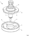
- FIG. 2 shows a solution according to the invention, which instead of the DIN 5480 toothing with a Circular teeth used by Wildhaber-Novikov.
- gearwheel 4 such a circular-arc toothing can still be added on the lathe or on a machining center by means of a milling tool, so that re-clamping and machining on the hobbing machine can be dispensed with.
- the driver element 6 the advantage is still considerably greater, since the inner contour can still be milled out as a depression here in a passage directly on the lathe or on a machining center.
- Drive plate and inner ring gear 7 are thus made uniform and integral in this solution, so that additional steps can be omitted.
- the driver element 6 further comprises on its underside a spur gear toothing of axial teeth 9, via which engagement in a counter-toothing of a second connector part can be produced.
- the driver element 6 is completely made of ferromagnetic material and the second connector part assigned an electromagnet, via which the driver element 6 is actuated, thus axially against the restoring force of a spring not shown here from the first connector part 2 away on the second also not shown here Connecting part is pulled to engage with the spur gear teeth.
- FIG. 3 shows another constructionally differently solved example with a toothed coupling, which has an outer diameter of 114 mm instead of in FIG. 2 shown variant with 80 mm. Corresponding elements are labeled the same.
- shaft-hub connector which has circular arc teeth instead of a spline made by hobbing which allows the use of a simpler, faster and cheaper manufacturing method for such shaft-hub connectors and tooth couplings made therewith.
Landscapes
- Engineering & Computer Science (AREA)
- General Engineering & Computer Science (AREA)
- Mechanical Engineering (AREA)
- Gears, Cams (AREA)
- Mechanical Operated Clutches (AREA)
- Gear Processing (AREA)
Applications Claiming Priority (1)
| Application Number | Priority Date | Filing Date | Title |
|---|---|---|---|
| DE102016124092.3A DE102016124092A1 (de) | 2016-12-12 | 2016-12-12 | Welle-Nabe-Verbinder, Zahnkupplung und Herstellungsverfahren für eine Welle-Nabe-Verbindung |
Publications (3)
| Publication Number | Publication Date |
|---|---|
| EP3354917A2 true EP3354917A2 (fr) | 2018-08-01 |
| EP3354917A3 EP3354917A3 (fr) | 2018-09-12 |
| EP3354917B1 EP3354917B1 (fr) | 2020-02-05 |
Family
ID=60654880
Family Applications (1)
| Application Number | Title | Priority Date | Filing Date |
|---|---|---|---|
| EP17206533.6A Active EP3354917B1 (fr) | 2016-12-12 | 2017-12-11 | Accouplement denté du raccordement arbre-moyeu et procédé de fabrication d'un raccordement arbre-moyeu |
Country Status (4)
| Country | Link |
|---|---|
| EP (1) | EP3354917B1 (fr) |
| CN (1) | CN108223596B (fr) |
| DE (1) | DE102016124092A1 (fr) |
| ES (1) | ES2773791T3 (fr) |
Families Citing this family (2)
| Publication number | Priority date | Publication date | Assignee | Title |
|---|---|---|---|---|
| US11834798B2 (en) | 2021-10-06 | 2023-12-05 | Caterpillar Paving Products Inc. | System for transferring torque from driveshafts to milling drums |
| CN115533466A (zh) * | 2022-11-10 | 2022-12-30 | 西马克工程(中国)有限公司 | 薄壁齿套的加工工艺 |
Family Cites Families (5)
| Publication number | Priority date | Publication date | Assignee | Title |
|---|---|---|---|---|
| US3584667A (en) * | 1966-09-19 | 1971-06-15 | Textron Inc | Coupling arrangement and tools for same |
| US4622840A (en) * | 1983-06-20 | 1986-11-18 | Neapco, Inc. | Method for drawing telescoping tubes for torque transmission |
| DE3635916C1 (de) * | 1986-10-22 | 1988-03-24 | Voith Gmbh J M | Verzahnung fuer eine Wellen-Nabenverbindung |
| DE102013217035A1 (de) * | 2013-08-27 | 2015-03-05 | Volkswagen Aktiengesellschaft | Verfahren zum Zentrieren eines Zentrierteils und Rotationsbauteils |
| TR201505304A2 (tr) * | 2015-04-30 | 2015-07-21 | Valeo Otomotiv Sanayi Ve Ticaret A S | Tahri̇k plakasina sahi̇p bi̇r güç aktarim düzeneği̇ |
-
2016
- 2016-12-12 DE DE102016124092.3A patent/DE102016124092A1/de not_active Ceased
-
2017
- 2017-12-11 ES ES17206533T patent/ES2773791T3/es active Active
- 2017-12-11 EP EP17206533.6A patent/EP3354917B1/fr active Active
- 2017-12-11 CN CN201711308852.7A patent/CN108223596B/zh active Active
Non-Patent Citations (1)
| Title |
|---|
| None |
Also Published As
| Publication number | Publication date |
|---|---|
| DE102016124092A1 (de) | 2018-06-14 |
| EP3354917B1 (fr) | 2020-02-05 |
| CN108223596A (zh) | 2018-06-29 |
| ES2773791T3 (es) | 2020-07-14 |
| CN108223596B (zh) | 2021-12-07 |
| EP3354917A3 (fr) | 2018-09-12 |
Similar Documents
| Publication | Publication Date | Title |
|---|---|---|
| EP0717212B1 (fr) | Synchronisateur de boíte de vitesse | |
| DE4240131C2 (de) | Verbindung zwischen Gelenkinnenteil und Antriebswelle | |
| EP2913561A1 (fr) | Système d'engrenage planétaire motorisé et procédé permettant de relier un moteur à un engrenage planétaire pour fabriquer un agencement moteur-engrenage planétaire | |
| DE10220372A1 (de) | Mehreckige Grenzfläche zwischen antreibenden und angetriebenen Komponenten | |
| WO2009059589A1 (fr) | Élément d'accouplement pour transmettre des couples de rotation, et unité d'entraînement munie de l'élément d'accouplement | |
| DE102019130423A1 (de) | Antriebsstrang | |
| EP3354917B1 (fr) | Accouplement denté du raccordement arbre-moyeu et procédé de fabrication d'un raccordement arbre-moyeu | |
| EP3620677A1 (fr) | Embrayage multidisque | |
| DE19915027A1 (de) | Getriebeteil und Verfahren zum Formen eines Getriebeteils | |
| DE102012202446A1 (de) | Getrieberad, insbesondere Sonnenrad für ein Differenzialgetriebe | |
| EP1945957B1 (fr) | Dispositif pour maintenir une liaison arbre-moyeu entre deux arbres | |
| EP3458741A1 (fr) | Dispositif de raccordement servant à raccorder une pluralité d'éléments d'une masse antivibratoire | |
| DE102011102288A1 (de) | Vorrichtung und Verfahren zur Herstellung eines Stirnrads mit einer Schrägverzahnung | |
| DE102011119574B4 (de) | Verfahren zum Herstellen eines Kupplungskörpers | |
| DE102010036277A1 (de) | Kupplungskörper für ein Gangrad eines Schaltgetriebes sowie Gangrad mit Kupplungskörper | |
| DE102015121705A1 (de) | Kupplungsanordnung, insbesondere zum optionalen Verbinden eines Luftverdichters mit einer Antriebseinrichtung | |
| DE102006023098B3 (de) | Mehrfach-Synchronisiereinheit für ein Schaltgetriebe | |
| DE102011100985A1 (de) | Antriebsverbindung | |
| EP2478244B1 (fr) | Manchon d'actionnement pour boîte de vitesses mécanique | |
| DE102015108991A1 (de) | Nabe, Schiebemuffe und Synchronisationsvorrichtung sowie Verfahren zur Herstellung einer Nabe und Verfahren zur Herstellung einer Schiebemuffe | |
| EP3869057B1 (fr) | Pignon, ainsi que procédé de fabrication d'un disque d'embrayage pour un pignon | |
| DE102014210631A1 (de) | Blechzylinder mit Mitnahmeprofil und Verfahren zur Herstellung | |
| EP1552175A1 (fr) | Joint de cardan de type rzeppa | |
| DE102022005001B4 (de) | Kraftempfangsbauteil und getriebebaugruppe | |
| DE102018126551B3 (de) | Stirnraddifferential und Verfahren zu dessen Herstellung |
Legal Events
| Date | Code | Title | Description |
|---|---|---|---|
| PUAI | Public reference made under article 153(3) epc to a published international application that has entered the european phase |
Free format text: ORIGINAL CODE: 0009012 |
|
| STAA | Information on the status of an ep patent application or granted ep patent |
Free format text: STATUS: THE APPLICATION HAS BEEN PUBLISHED |
|
| AK | Designated contracting states |
Kind code of ref document: A2 Designated state(s): AL AT BE BG CH CY CZ DE DK EE ES FI FR GB GR HR HU IE IS IT LI LT LU LV MC MK MT NL NO PL PT RO RS SE SI SK SM TR |
|
| AX | Request for extension of the european patent |
Extension state: BA ME |
|
| PUAL | Search report despatched |
Free format text: ORIGINAL CODE: 0009013 |
|
| AK | Designated contracting states |
Kind code of ref document: A3 Designated state(s): AL AT BE BG CH CY CZ DE DK EE ES FI FR GB GR HR HU IE IS IT LI LT LU LV MC MK MT NL NO PL PT RO RS SE SI SK SM TR |
|
| AX | Request for extension of the european patent |
Extension state: BA ME |
|
| RIC1 | Information provided on ipc code assigned before grant |
Ipc: F16D 1/06 20060101AFI20180806BHEP Ipc: F16D 27/00 20060101ALI20180806BHEP Ipc: B23F 17/00 20060101ALI20180806BHEP Ipc: F16D 1/108 20060101ALI20180806BHEP Ipc: F16D 1/10 20060101ALI20180806BHEP |
|
| STAA | Information on the status of an ep patent application or granted ep patent |
Free format text: STATUS: REQUEST FOR EXAMINATION WAS MADE |
|
| 17P | Request for examination filed |
Effective date: 20190312 |
|
| RBV | Designated contracting states (corrected) |
Designated state(s): AL AT BE BG CH CY CZ DE DK EE ES FI FR GB GR HR HU IE IS IT LI LT LU LV MC MK MT NL NO PL PT RO RS SE SI SK SM TR |
|
| GRAP | Despatch of communication of intention to grant a patent |
Free format text: ORIGINAL CODE: EPIDOSNIGR1 |
|
| STAA | Information on the status of an ep patent application or granted ep patent |
Free format text: STATUS: GRANT OF PATENT IS INTENDED |
|
| INTG | Intention to grant announced |
Effective date: 20190711 |
|
| RIC1 | Information provided on ipc code assigned before grant |
Ipc: B23F 17/00 20060101ALI20190628BHEP Ipc: F16D 1/104 20060101ALI20190628BHEP Ipc: F16D 1/06 20060101AFI20190628BHEP Ipc: F16D 1/10 20060101ALI20190628BHEP Ipc: F16D 27/00 20060101ALI20190628BHEP |
|
| GRAS | Grant fee paid |
Free format text: ORIGINAL CODE: EPIDOSNIGR3 |
|
| GRAA | (expected) grant |
Free format text: ORIGINAL CODE: 0009210 |
|
| STAA | Information on the status of an ep patent application or granted ep patent |
Free format text: STATUS: THE PATENT HAS BEEN GRANTED |
|
| AK | Designated contracting states |
Kind code of ref document: B1 Designated state(s): AL AT BE BG CH CY CZ DE DK EE ES FI FR GB GR HR HU IE IS IT LI LT LU LV MC MK MT NL NO PL PT RO RS SE SI SK SM TR |
|
| REG | Reference to a national code |
Ref country code: GB Ref legal event code: FG4D Free format text: NOT ENGLISH |
|
| REG | Reference to a national code |
Ref country code: AT Ref legal event code: REF Ref document number: 1230127 Country of ref document: AT Kind code of ref document: T Effective date: 20200215 |
|
| REG | Reference to a national code |
Ref country code: DE Ref legal event code: R096 Ref document number: 502017003694 Country of ref document: DE |
|
| REG | Reference to a national code |
Ref country code: IE Ref legal event code: FG4D Free format text: LANGUAGE OF EP DOCUMENT: GERMAN |
|
| REG | Reference to a national code |
Ref country code: CH Ref legal event code: EP |
|
| REG | Reference to a national code |
Ref country code: NL Ref legal event code: MP Effective date: 20200205 |
|
| REG | Reference to a national code |
Ref country code: ES Ref legal event code: FG2A Ref document number: 2773791 Country of ref document: ES Kind code of ref document: T3 Effective date: 20200714 |
|
| PG25 | Lapsed in a contracting state [announced via postgrant information from national office to epo] |
Ref country code: NO Free format text: LAPSE BECAUSE OF FAILURE TO SUBMIT A TRANSLATION OF THE DESCRIPTION OR TO PAY THE FEE WITHIN THE PRESCRIBED TIME-LIMIT Effective date: 20200505 Ref country code: PT Free format text: LAPSE BECAUSE OF FAILURE TO SUBMIT A TRANSLATION OF THE DESCRIPTION OR TO PAY THE FEE WITHIN THE PRESCRIBED TIME-LIMIT Effective date: 20200628 Ref country code: FI Free format text: LAPSE BECAUSE OF FAILURE TO SUBMIT A TRANSLATION OF THE DESCRIPTION OR TO PAY THE FEE WITHIN THE PRESCRIBED TIME-LIMIT Effective date: 20200205 Ref country code: RS Free format text: LAPSE BECAUSE OF FAILURE TO SUBMIT A TRANSLATION OF THE DESCRIPTION OR TO PAY THE FEE WITHIN THE PRESCRIBED TIME-LIMIT Effective date: 20200205 |
|
| REG | Reference to a national code |
Ref country code: LT Ref legal event code: MG4D |
|
| PG25 | Lapsed in a contracting state [announced via postgrant information from national office to epo] |
Ref country code: HR Free format text: LAPSE BECAUSE OF FAILURE TO SUBMIT A TRANSLATION OF THE DESCRIPTION OR TO PAY THE FEE WITHIN THE PRESCRIBED TIME-LIMIT Effective date: 20200205 Ref country code: IS Free format text: LAPSE BECAUSE OF FAILURE TO SUBMIT A TRANSLATION OF THE DESCRIPTION OR TO PAY THE FEE WITHIN THE PRESCRIBED TIME-LIMIT Effective date: 20200605 Ref country code: GR Free format text: LAPSE BECAUSE OF FAILURE TO SUBMIT A TRANSLATION OF THE DESCRIPTION OR TO PAY THE FEE WITHIN THE PRESCRIBED TIME-LIMIT Effective date: 20200506 Ref country code: BG Free format text: LAPSE BECAUSE OF FAILURE TO SUBMIT A TRANSLATION OF THE DESCRIPTION OR TO PAY THE FEE WITHIN THE PRESCRIBED TIME-LIMIT Effective date: 20200505 Ref country code: SE Free format text: LAPSE BECAUSE OF FAILURE TO SUBMIT A TRANSLATION OF THE DESCRIPTION OR TO PAY THE FEE WITHIN THE PRESCRIBED TIME-LIMIT Effective date: 20200205 Ref country code: LV Free format text: LAPSE BECAUSE OF FAILURE TO SUBMIT A TRANSLATION OF THE DESCRIPTION OR TO PAY THE FEE WITHIN THE PRESCRIBED TIME-LIMIT Effective date: 20200205 |
|
| PG25 | Lapsed in a contracting state [announced via postgrant information from national office to epo] |
Ref country code: NL Free format text: LAPSE BECAUSE OF FAILURE TO SUBMIT A TRANSLATION OF THE DESCRIPTION OR TO PAY THE FEE WITHIN THE PRESCRIBED TIME-LIMIT Effective date: 20200205 |
|
| PG25 | Lapsed in a contracting state [announced via postgrant information from national office to epo] |
Ref country code: RO Free format text: LAPSE BECAUSE OF FAILURE TO SUBMIT A TRANSLATION OF THE DESCRIPTION OR TO PAY THE FEE WITHIN THE PRESCRIBED TIME-LIMIT Effective date: 20200205 Ref country code: LT Free format text: LAPSE BECAUSE OF FAILURE TO SUBMIT A TRANSLATION OF THE DESCRIPTION OR TO PAY THE FEE WITHIN THE PRESCRIBED TIME-LIMIT Effective date: 20200205 Ref country code: CZ Free format text: LAPSE BECAUSE OF FAILURE TO SUBMIT A TRANSLATION OF THE DESCRIPTION OR TO PAY THE FEE WITHIN THE PRESCRIBED TIME-LIMIT Effective date: 20200205 Ref country code: SK Free format text: LAPSE BECAUSE OF FAILURE TO SUBMIT A TRANSLATION OF THE DESCRIPTION OR TO PAY THE FEE WITHIN THE PRESCRIBED TIME-LIMIT Effective date: 20200205 Ref country code: DK Free format text: LAPSE BECAUSE OF FAILURE TO SUBMIT A TRANSLATION OF THE DESCRIPTION OR TO PAY THE FEE WITHIN THE PRESCRIBED TIME-LIMIT Effective date: 20200205 Ref country code: EE Free format text: LAPSE BECAUSE OF FAILURE TO SUBMIT A TRANSLATION OF THE DESCRIPTION OR TO PAY THE FEE WITHIN THE PRESCRIBED TIME-LIMIT Effective date: 20200205 Ref country code: SM Free format text: LAPSE BECAUSE OF FAILURE TO SUBMIT A TRANSLATION OF THE DESCRIPTION OR TO PAY THE FEE WITHIN THE PRESCRIBED TIME-LIMIT Effective date: 20200205 |
|
| REG | Reference to a national code |
Ref country code: DE Ref legal event code: R097 Ref document number: 502017003694 Country of ref document: DE |
|
| PLBE | No opposition filed within time limit |
Free format text: ORIGINAL CODE: 0009261 |
|
| STAA | Information on the status of an ep patent application or granted ep patent |
Free format text: STATUS: NO OPPOSITION FILED WITHIN TIME LIMIT |
|
| 26N | No opposition filed |
Effective date: 20201106 |
|
| PG25 | Lapsed in a contracting state [announced via postgrant information from national office to epo] |
Ref country code: IT Free format text: LAPSE BECAUSE OF FAILURE TO SUBMIT A TRANSLATION OF THE DESCRIPTION OR TO PAY THE FEE WITHIN THE PRESCRIBED TIME-LIMIT Effective date: 20200205 |
|
| PG25 | Lapsed in a contracting state [announced via postgrant information from national office to epo] |
Ref country code: SI Free format text: LAPSE BECAUSE OF FAILURE TO SUBMIT A TRANSLATION OF THE DESCRIPTION OR TO PAY THE FEE WITHIN THE PRESCRIBED TIME-LIMIT Effective date: 20200205 Ref country code: PL Free format text: LAPSE BECAUSE OF FAILURE TO SUBMIT A TRANSLATION OF THE DESCRIPTION OR TO PAY THE FEE WITHIN THE PRESCRIBED TIME-LIMIT Effective date: 20200205 |
|
| REG | Reference to a national code |
Ref country code: CH Ref legal event code: PL |
|
| PG25 | Lapsed in a contracting state [announced via postgrant information from national office to epo] |
Ref country code: MC Free format text: LAPSE BECAUSE OF FAILURE TO SUBMIT A TRANSLATION OF THE DESCRIPTION OR TO PAY THE FEE WITHIN THE PRESCRIBED TIME-LIMIT Effective date: 20200205 |
|
| REG | Reference to a national code |
Ref country code: BE Ref legal event code: MM Effective date: 20201231 |
|
| PG25 | Lapsed in a contracting state [announced via postgrant information from national office to epo] |
Ref country code: IE Free format text: LAPSE BECAUSE OF NON-PAYMENT OF DUE FEES Effective date: 20201211 Ref country code: LU Free format text: LAPSE BECAUSE OF NON-PAYMENT OF DUE FEES Effective date: 20201211 |
|
| PG25 | Lapsed in a contracting state [announced via postgrant information from national office to epo] |
Ref country code: CH Free format text: LAPSE BECAUSE OF NON-PAYMENT OF DUE FEES Effective date: 20201231 Ref country code: LI Free format text: LAPSE BECAUSE OF NON-PAYMENT OF DUE FEES Effective date: 20201231 |
|
| PG25 | Lapsed in a contracting state [announced via postgrant information from national office to epo] |
Ref country code: TR Free format text: LAPSE BECAUSE OF FAILURE TO SUBMIT A TRANSLATION OF THE DESCRIPTION OR TO PAY THE FEE WITHIN THE PRESCRIBED TIME-LIMIT Effective date: 20200205 Ref country code: MT Free format text: LAPSE BECAUSE OF FAILURE TO SUBMIT A TRANSLATION OF THE DESCRIPTION OR TO PAY THE FEE WITHIN THE PRESCRIBED TIME-LIMIT Effective date: 20200205 Ref country code: CY Free format text: LAPSE BECAUSE OF FAILURE TO SUBMIT A TRANSLATION OF THE DESCRIPTION OR TO PAY THE FEE WITHIN THE PRESCRIBED TIME-LIMIT Effective date: 20200205 |
|
| PG25 | Lapsed in a contracting state [announced via postgrant information from national office to epo] |
Ref country code: MK Free format text: LAPSE BECAUSE OF FAILURE TO SUBMIT A TRANSLATION OF THE DESCRIPTION OR TO PAY THE FEE WITHIN THE PRESCRIBED TIME-LIMIT Effective date: 20200205 Ref country code: AL Free format text: LAPSE BECAUSE OF FAILURE TO SUBMIT A TRANSLATION OF THE DESCRIPTION OR TO PAY THE FEE WITHIN THE PRESCRIBED TIME-LIMIT Effective date: 20200205 |
|
| PG25 | Lapsed in a contracting state [announced via postgrant information from national office to epo] |
Ref country code: BE Free format text: LAPSE BECAUSE OF NON-PAYMENT OF DUE FEES Effective date: 20201231 |
|
| REG | Reference to a national code |
Ref country code: AT Ref legal event code: MM01 Ref document number: 1230127 Country of ref document: AT Kind code of ref document: T Effective date: 20221211 |
|
| PG25 | Lapsed in a contracting state [announced via postgrant information from national office to epo] |
Ref country code: AT Free format text: LAPSE BECAUSE OF NON-PAYMENT OF DUE FEES Effective date: 20221211 |
|
| PG25 | Lapsed in a contracting state [announced via postgrant information from national office to epo] |
Ref country code: AT Free format text: LAPSE BECAUSE OF NON-PAYMENT OF DUE FEES Effective date: 20221211 |
|
| REG | Reference to a national code |
Ref country code: DE Ref legal event code: R081 Ref document number: 502017003694 Country of ref document: DE Owner name: DORMAKABA DEUTSCHLAND GMBH, DE Free format text: FORMER OWNER: KABA GALLENSCHUETZ GMBH, 77815 BUEHL, DE |
|
| REG | Reference to a national code |
Ref country code: GB Ref legal event code: 732E Free format text: REGISTERED BETWEEN 20250911 AND 20250917 |
|
| PGFP | Annual fee paid to national office [announced via postgrant information from national office to epo] |
Ref country code: DE Payment date: 20251211 Year of fee payment: 9 |
|
| PGFP | Annual fee paid to national office [announced via postgrant information from national office to epo] |
Ref country code: GB Payment date: 20251219 Year of fee payment: 9 |
|
| PGFP | Annual fee paid to national office [announced via postgrant information from national office to epo] |
Ref country code: FR Payment date: 20251229 Year of fee payment: 9 |
|
| PGFP | Annual fee paid to national office [announced via postgrant information from national office to epo] |
Ref country code: ES Payment date: 20260130 Year of fee payment: 9 |
|
| PGFP | Annual fee paid to national office [announced via postgrant information from national office to epo] |
Ref country code: AT Payment date: 20260410 Year of fee payment: 5 |
|
| REG | Reference to a national code |
Ref country code: ES Ref legal event code: PC2A Owner name: DORMAKABA DEUTSCHLAND GMBH Effective date: 20260414 |