EP3354930A1 - Isolateurs à trois paramètres contenant des ensembles amortisseurs comprenant une membrane déroulante - Google Patents
Isolateurs à trois paramètres contenant des ensembles amortisseurs comprenant une membrane déroulante Download PDFInfo
- Publication number
- EP3354930A1 EP3354930A1 EP18152853.0A EP18152853A EP3354930A1 EP 3354930 A1 EP3354930 A1 EP 3354930A1 EP 18152853 A EP18152853 A EP 18152853A EP 3354930 A1 EP3354930 A1 EP 3354930A1
- Authority
- EP
- European Patent Office
- Prior art keywords
- rolling
- isolator
- seal
- piston
- parameter
- Prior art date
- Legal status (The legal status is an assumption and is not a legal conclusion. Google has not performed a legal analysis and makes no representation as to the accuracy of the status listed.)
- Granted
Links
Images


Classifications
-
- F—MECHANICAL ENGINEERING; LIGHTING; HEATING; WEAPONS; BLASTING
- F16—ENGINEERING ELEMENTS AND UNITS; GENERAL MEASURES FOR PRODUCING AND MAINTAINING EFFECTIVE FUNCTIONING OF MACHINES OR INSTALLATIONS; THERMAL INSULATION IN GENERAL
- F16F—SPRINGS; SHOCK-ABSORBERS; MEANS FOR DAMPING VIBRATION
- F16F15/00—Suppression of vibrations in systems; Means or arrangements for avoiding or reducing out-of-balance forces, e.g. due to motion
- F16F15/02—Suppression of vibrations of non-rotating, e.g. reciprocating systems; Suppression of vibrations of rotating systems by use of members not moving with the rotating systems
- F16F15/023—Suppression of vibrations of non-rotating, e.g. reciprocating systems; Suppression of vibrations of rotating systems by use of members not moving with the rotating systems using fluid means
-
- F—MECHANICAL ENGINEERING; LIGHTING; HEATING; WEAPONS; BLASTING
- F16—ENGINEERING ELEMENTS AND UNITS; GENERAL MEASURES FOR PRODUCING AND MAINTAINING EFFECTIVE FUNCTIONING OF MACHINES OR INSTALLATIONS; THERMAL INSULATION IN GENERAL
- F16F—SPRINGS; SHOCK-ABSORBERS; MEANS FOR DAMPING VIBRATION
- F16F15/00—Suppression of vibrations in systems; Means or arrangements for avoiding or reducing out-of-balance forces, e.g. due to motion
- F16F15/02—Suppression of vibrations of non-rotating, e.g. reciprocating systems; Suppression of vibrations of rotating systems by use of members not moving with the rotating systems
- F16F15/022—Suppression of vibrations of non-rotating, e.g. reciprocating systems; Suppression of vibrations of rotating systems by use of members not moving with the rotating systems using dampers and springs in combination
-
- B—PERFORMING OPERATIONS; TRANSPORTING
- B64—AIRCRAFT; AVIATION; COSMONAUTICS
- B64G—COSMONAUTICS; VEHICLES OR EQUIPMENT THEREFOR
- B64G1/00—Cosmonautic vehicles
- B64G1/22—Parts of, or equipment specially adapted for fitting in or to, cosmonautic vehicles
- B64G1/228—Damping of high-frequency vibration effects on spacecraft elements, e.g. by using acoustic vibration dampers
-
- B—PERFORMING OPERATIONS; TRANSPORTING
- B64—AIRCRAFT; AVIATION; COSMONAUTICS
- B64G—COSMONAUTICS; VEHICLES OR EQUIPMENT THEREFOR
- B64G1/00—Cosmonautic vehicles
- B64G1/22—Parts of, or equipment specially adapted for fitting in or to, cosmonautic vehicles
- B64G1/64—Systems for coupling or separating cosmonautic vehicles or parts thereof, e.g. docking arrangements
- B64G1/641—Interstage or payload connectors
- B64G1/6425—Interstage or payload connectors arrangements for damping vibrations
-
- B—PERFORMING OPERATIONS; TRANSPORTING
- B64—AIRCRAFT; AVIATION; COSMONAUTICS
- B64G—COSMONAUTICS; VEHICLES OR EQUIPMENT THEREFOR
- B64G1/00—Cosmonautic vehicles
- B64G1/22—Parts of, or equipment specially adapted for fitting in or to, cosmonautic vehicles
- B64G1/66—Arrangements or adaptations of apparatus or instruments, not otherwise provided for
-
- F—MECHANICAL ENGINEERING; LIGHTING; HEATING; WEAPONS; BLASTING
- F16—ENGINEERING ELEMENTS AND UNITS; GENERAL MEASURES FOR PRODUCING AND MAINTAINING EFFECTIVE FUNCTIONING OF MACHINES OR INSTALLATIONS; THERMAL INSULATION IN GENERAL
- F16F—SPRINGS; SHOCK-ABSORBERS; MEANS FOR DAMPING VIBRATION
- F16F13/00—Units comprising springs of the non-fluid type as well as vibration-dampers, shock-absorbers, or fluid springs
- F16F13/005—Units comprising springs of the non-fluid type as well as vibration-dampers, shock-absorbers, or fluid springs comprising both a wound spring and a damper, e.g. a friction damper
- F16F13/007—Units comprising springs of the non-fluid type as well as vibration-dampers, shock-absorbers, or fluid springs comprising both a wound spring and a damper, e.g. a friction damper the damper being a fluid damper
-
- F—MECHANICAL ENGINEERING; LIGHTING; HEATING; WEAPONS; BLASTING
- F16—ENGINEERING ELEMENTS AND UNITS; GENERAL MEASURES FOR PRODUCING AND MAINTAINING EFFECTIVE FUNCTIONING OF MACHINES OR INSTALLATIONS; THERMAL INSULATION IN GENERAL
- F16F—SPRINGS; SHOCK-ABSORBERS; MEANS FOR DAMPING VIBRATION
- F16F9/00—Springs, vibration-dampers, shock-absorbers, or similarly-constructed movement-dampers using a fluid or the equivalent as damping medium
- F16F9/10—Springs, vibration-dampers, shock-absorbers, or similarly-constructed movement-dampers using a fluid or the equivalent as damping medium using liquid only; using a fluid of which the nature is immaterial
- F16F9/14—Devices with one or more members, e.g. pistons, vanes, moving to and fro in chambers and using throttling effect
- F16F9/16—Devices with one or more members, e.g. pistons, vanes, moving to and fro in chambers and using throttling effect involving only straight-line movement of the effective parts
- F16F9/18—Devices with one or more members, e.g. pistons, vanes, moving to and fro in chambers and using throttling effect involving only straight-line movement of the effective parts with a closed cylinder and a piston separating two or more working spaces therein
- F16F9/20—Devices with one or more members, e.g. pistons, vanes, moving to and fro in chambers and using throttling effect involving only straight-line movement of the effective parts with a closed cylinder and a piston separating two or more working spaces therein with the piston-rod extending through both ends of the cylinder, e.g. constant-volume dampers
-
- F—MECHANICAL ENGINEERING; LIGHTING; HEATING; WEAPONS; BLASTING
- F16—ENGINEERING ELEMENTS AND UNITS; GENERAL MEASURES FOR PRODUCING AND MAINTAINING EFFECTIVE FUNCTIONING OF MACHINES OR INSTALLATIONS; THERMAL INSULATION IN GENERAL
- F16F—SPRINGS; SHOCK-ABSORBERS; MEANS FOR DAMPING VIBRATION
- F16F9/00—Springs, vibration-dampers, shock-absorbers, or similarly-constructed movement-dampers using a fluid or the equivalent as damping medium
- F16F9/32—Details
- F16F9/3207—Constructional features
- F16F9/3235—Constructional features of cylinders
- F16F9/3257—Constructional features of cylinders in twin-tube type devices
-
- F—MECHANICAL ENGINEERING; LIGHTING; HEATING; WEAPONS; BLASTING
- F16—ENGINEERING ELEMENTS AND UNITS; GENERAL MEASURES FOR PRODUCING AND MAINTAINING EFFECTIVE FUNCTIONING OF MACHINES OR INSTALLATIONS; THERMAL INSULATION IN GENERAL
- F16F—SPRINGS; SHOCK-ABSORBERS; MEANS FOR DAMPING VIBRATION
- F16F9/00—Springs, vibration-dampers, shock-absorbers, or similarly-constructed movement-dampers using a fluid or the equivalent as damping medium
- F16F9/32—Details
- F16F9/36—Special sealings, including sealings or guides for piston-rods
- F16F9/362—Combination of sealing and guide arrangements for piston rods
-
- B—PERFORMING OPERATIONS; TRANSPORTING
- B64—AIRCRAFT; AVIATION; COSMONAUTICS
- B64G—COSMONAUTICS; VEHICLES OR EQUIPMENT THEREFOR
- B64G1/00—Cosmonautic vehicles
- B64G1/22—Parts of, or equipment specially adapted for fitting in or to, cosmonautic vehicles
-
- B—PERFORMING OPERATIONS; TRANSPORTING
- B64—AIRCRAFT; AVIATION; COSMONAUTICS
- B64G—COSMONAUTICS; VEHICLES OR EQUIPMENT THEREFOR
- B64G1/00—Cosmonautic vehicles
- B64G1/22—Parts of, or equipment specially adapted for fitting in or to, cosmonautic vehicles
- B64G1/24—Guiding or controlling apparatus, e.g. for attitude control
- B64G1/28—Guiding or controlling apparatus, e.g. for attitude control using inertia or gyro effect
- B64G1/283—Guiding or controlling apparatus, e.g. for attitude control using inertia or gyro effect using reaction wheels
-
- B—PERFORMING OPERATIONS; TRANSPORTING
- B64—AIRCRAFT; AVIATION; COSMONAUTICS
- B64G—COSMONAUTICS; VEHICLES OR EQUIPMENT THEREFOR
- B64G1/00—Cosmonautic vehicles
- B64G1/22—Parts of, or equipment specially adapted for fitting in or to, cosmonautic vehicles
- B64G1/24—Guiding or controlling apparatus, e.g. for attitude control
- B64G1/28—Guiding or controlling apparatus, e.g. for attitude control using inertia or gyro effect
- B64G1/286—Guiding or controlling apparatus, e.g. for attitude control using inertia or gyro effect using control momentum gyroscopes (CMGs)
-
- F—MECHANICAL ENGINEERING; LIGHTING; HEATING; WEAPONS; BLASTING
- F16—ENGINEERING ELEMENTS AND UNITS; GENERAL MEASURES FOR PRODUCING AND MAINTAINING EFFECTIVE FUNCTIONING OF MACHINES OR INSTALLATIONS; THERMAL INSULATION IN GENERAL
- F16F—SPRINGS; SHOCK-ABSORBERS; MEANS FOR DAMPING VIBRATION
- F16F2222/00—Special physical effects, e.g. nature of damping effects
- F16F2222/12—Fluid damping
-
- F—MECHANICAL ENGINEERING; LIGHTING; HEATING; WEAPONS; BLASTING
- F16—ENGINEERING ELEMENTS AND UNITS; GENERAL MEASURES FOR PRODUCING AND MAINTAINING EFFECTIVE FUNCTIONING OF MACHINES OR INSTALLATIONS; THERMAL INSULATION IN GENERAL
- F16F—SPRINGS; SHOCK-ABSORBERS; MEANS FOR DAMPING VIBRATION
- F16F2232/00—Nature of movement
- F16F2232/08—Linear
-
- F—MECHANICAL ENGINEERING; LIGHTING; HEATING; WEAPONS; BLASTING
- F16—ENGINEERING ELEMENTS AND UNITS; GENERAL MEASURES FOR PRODUCING AND MAINTAINING EFFECTIVE FUNCTIONING OF MACHINES OR INSTALLATIONS; THERMAL INSULATION IN GENERAL
- F16F—SPRINGS; SHOCK-ABSORBERS; MEANS FOR DAMPING VIBRATION
- F16F2238/00—Type of springs or dampers
- F16F2238/02—Springs
- F16F2238/026—Springs wound- or coil-like
-
- F—MECHANICAL ENGINEERING; LIGHTING; HEATING; WEAPONS; BLASTING
- F16—ENGINEERING ELEMENTS AND UNITS; GENERAL MEASURES FOR PRODUCING AND MAINTAINING EFFECTIVE FUNCTIONING OF MACHINES OR INSTALLATIONS; THERMAL INSULATION IN GENERAL
- F16F—SPRINGS; SHOCK-ABSORBERS; MEANS FOR DAMPING VIBRATION
- F16F2238/00—Type of springs or dampers
- F16F2238/04—Damper
Definitions
- Embodiments of the present invention relates generally to isolators and, more particularly, to three parameter isolators containing rolling seal damper assemblies.
- Vibration isolation systems are employed in a wide variety of applications to minimize the transmission of disturbances forces between two bodies or structures. Satellite and other spacecraft, for example, are commonly equipped with vibration isolation systems to minimize the transmission of vibratory forces or jitter emitted from attitude adjustment devices (e.g., control moment gyroscopes or reaction wheel arrays) to other vibration-sensitive components (e.g., optical payloads) onboard the spacecraft.
- attitude adjustment devices e.g., control moment gyroscopes or reaction wheel arrays
- other vibration-sensitive components e.g., optical payloads
- the performance of such vibration isolation system may be determined by several factors including the manner in which the isolators are arranged and the vibration attenuation characteristics of each individual isolator.
- Vibration isolation systems employing three parameter isolators which behave mechanically as a primary spring in parallel with a series-coupled tuning spring and damper, provide superior attenuation of high frequency vibratory forces as compared to vibration isolation systems employing other types of passive isolators, such as viscoelastic isolators.
- An example of a three parameter isolator is the D-STRUT® isolator developed and commercially marketed by Honeywell, Inc., currently headquartered in Morristown, New Jersey.
- Such isolators are often passive, single Degree of Freedom (DOF), axially-damping devices well-suited for usage within multi-point mounting arrangements. While capable of providing high performance vibration attenuation, existing three parameter isolators remain limited in certain respects. For example, high manufacturing costs and lengthy lead times have hampered the widespread adoption of three parameter isolators in non-spaceborne applications.
- DOF Degree of Freedom
- Embodiments of three parameter isolators including rolling seal damper assemblies are provided.
- the three parameter isolator includes first and second isolator end portions, which are opposed along a working axis.
- a main spring and a tuning spring are mechanically coupled in parallel between the first and second isolator end portions.
- a rolling seal damper assembly is further mechanically coupled between the first and second isolator end portions in parallel with the main spring and in series with the tuning spring.
- the rolling seal damper assembly includes a first hydraulic chamber, a second hydraulic chamber fluidly coupled to the first hydraulic chamber, and first and second rolling diaphragm seals partially bounding or defining the first and second hydraulic chambers, respectively.
- the rolling seal damper assembly also contains a thermal compensator piston to which the first rolling diaphragm seal is sealingly attached.
- the three parameter isolator includes an outer isolator housing assembly, a main spring forming part of the outer isolator housing assembly, and a tuning spring in parallel with the main spring and contained within the outer isolator housing assembly.
- the three parameter isolator further includes a rolling seal damper assembly in parallel with the main spring, in series with the tuning spring, and further contained within the outer isolator housing assembly.
- the rolling seal damper assembly includes a first hydraulic chamber contained within the outer isolator housing assembly, and a first rolling diaphragm seal at least partially defining the first hydraulic chamber.
- the rolling seal damper assembly further may further include a second rolling diaphragm seal, and the first and second rolling diaphragm seals may be located on opposing sides of the damper piston as taken along a working axis of the three parameter isolator.
- the first and second rolling diaphragm seals may be substantially coaxial with the working axis.
- the three parameter isolator includes inner and outer load paths extending in parallel through at least a portion of the three parameter isolator.
- a main spring is positioned in the outer load path
- a tuning spring is positioned in the inner load path
- a rolling seal damper assembly is positioned in the inner load path.
- the rolling seal damper assembly includes: (i) a thermal compensator piston having an outer annular sidewall, (ii) static structure surrounding the thermal compensator piston and having an inner annular sidewall, (iii) a thermal compensator spring biasing the thermal compensator piston toward an extended position, and (iv) a rolling diaphragm seal extending between the thermal compensator piston and the static structure. The rolling diaphragm seal contacts the inner and outer annular sidewalls at least when the thermal compensator piston resides in the extended position.
- edge-welded metal bellows provide an enhanced stroke range-to-bellows length as compared to other types of metal bellows (e.g., deposited nickel bellows), which, in turn, allows favorable reductions in isolator size and weight.
- Edge-welded metal bellows are, however, costly to produce and usually require lengthy lead times due, at least part, to the manually-intensive nature of the edge welding process utilized to fabricate such bellows.
- dynamic seals such as sliding O-ring seals, can potentially be utilized in place of edge-welded bellows to bring about reductions in manufacturing costs, dynamic seals are often prone to leakage and may be incompatible with isolator designs requiring frictionless or near frictionless operation.
- the rolling seal damper assembly contains flexible rolling diaphragm seals, which seal hydraulic compartments or chambers included within the damper assembly.
- the rolling seal damper assembly may be placed in parallel and in series with a main spring and a tuning spring, respectively, further included in the three parameter isolator.
- the rolling seal damper assembly may also contain a Thermal Compensator (TC) including a TC piston, TC chamber, and a rolling diaphragm seal, which is sealing joined to the TC piston and which at least partially defines the TC chamber.
- TC Thermal Compensator
- the rolling seal damper assembly may further include a linear guide system, which confines off-axis movement of a damper piston structure to which at least one of the rolling diaphragm seals is sealingly attached.
- a linear guide system which confines off-axis movement of a damper piston structure to which at least one of the rolling diaphragm seals is sealingly attached.
- Still further benefits that may be provided by embodiments of the below-described three parameter isolator may include, but are not limited to, an extensive operative temperature range, robust vibration insensitivity, relatively broad stroke capabilities, high pressure capabilities, very low static spring rates, and long service lifespans.
- the below-described rolling seal damper assemblies allow disassembly (at the damper assembly level) as may facilitate more timely damper draining and re-filling with different fluid types of damper fluid during an initial tuning process.
- Embodiments of the three parameter isolator described herein can be utilized in various different types multipoint mounting arrangements. Usage of the below-described three parameters isolators is not restricted to any particular application or environment. It is noted, however, that embodiments of the three parameter isolators may be particularly well-suited for usage in terrestrial applications due, at least in part, to reductions in manufacturing cost. For example, embodiments of the three parameter isolator may be advantageously utilized within non-spaceborne vibration isolation systems, such as a Gas Turbine Engine (GTE) isolation system.
- GTE Gas Turbine Engine
- An exemplary embodiment of a single DOF (axially-damping), three parameter isolator including a rolling seal damper assemblies is described below in conjunction with FIGs. 3-5 .
- FIG. 1 is a schematic representation of a passive three parameter isolator 10, as illustrated in accordance with the teachings of prior art.
- Three parameter isolator 10 is mechanically coupled between an isolated object "IO" and a platform "P.”
- platform P is a satellite or other spacecraft, while isolated object IO is an optical bench or other vibration-sensitive payload carried by the spacecraft.
- platform P is an aircraft and isolated object IO is a GTE, such as an Auxiliary Power Unit (APU), which generates vibrations that are desirably attenuated prior to reaching the aircraft fuselage.
- APU Auxiliary Power Unit
- platform P can be a different type of vehicle or structure, while isolated object IO can assume various other forms. As modeled in FIG.
- three parameter isolator 10 includes the following mechanical elements or components: (i) a first spring component K A , which is mechanically coupled between isolated object IO and platform P; (ii) a second spring component K B , which is mechanically coupled between isolated object IO and platform P in parallel with first spring component K A ; and (iii) a damper C A , which is mechanically coupled between isolated object IO and platform P in parallel with the first spring component K A and in series with the second spring component K B .
- FIG. 2 is a transmissibility plot illustrating the damping characteristics of three parameter isolator 10 (curve 12) as compared to a two parameter isolator (curve 14) and an undamped device (curve 16).
- the undamped device (curve 16) provides a relatively high peak gain at a threshold frequency, which, in the illustrated example, is moderately less than 10 hertz.
- the two parameter device (curve 14) provides a significantly lower peak gain at the threshold frequency, but an undesirably gradual decrease in gain with increasing frequency after the threshold frequency has been surpassed (referred to as "roll-off').
- the roll-off of the two parameter device is approximately 20 decibel per decade ("dB/decade").
- the three parameter device provides a low peak gain substantially equivalent to that achieved by the two parameter device (curve 14) and further provides a relatively steep roll-off of about 40 dB/decade.
- the three parameter device thus provides a significantly lower transmissibility at higher frequencies, as quantified in FIG. 2 by the area 20 bounded by curves 12 and 14.
- further discussion of three parameter isolators can be found in U.S. Pat. No.
- Passive three parameter isolators such as isolator 10 schematically illustrated in FIG. 1
- Passive three parameter isolators can thus be tuned to provide superior damping characteristics (e.g., lower overall transmissibilities) as compared to undamped devices and two parameter devices over a given frequency range.
- the stiffness and damping characteristics of passive three parameter isolators are independently tunable. Consequently, when six or more isolators are arranged in a multi-point system, each three parameter isolator can be specifically tuned to provide optimal stiffness and damping in each degree of freedom to minimize vibration transmittance between a platform and an isolated object supported thereby.
- An exemplary embodiment of a single DOF (axially-damping), three parameter isolator including a rolling seal damper assemblies will now be described below in conjunction with FIGs. 3-6 .
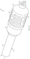
- FIGs. 3 and 4 are isometric and cross-sectional views, respectively, of an exemplary embodiment of a three parameter isolator 40 suitable for usage as one or all of three parameter isolators 16 shown in FIG. 1 .
- Exemplary three parameter isolator 40 includes a first isolator end portion 42 and a second, opposing end isolator portion 44.
- Isolator end portions 42, 44 are spaced along the longitudinal or working axis of isolator 40, which is represented in FIG. 3 by double-headed arrow 46 and corresponds to the X-axis identified in FIG. 4 by coordinate legend 48.
- Isolator end portions 42, 44 serve as opposing mechanical inputs/outputs of three parameter isolator 40.
- first isolator end portion 42 When isolator 40 is deployed within a vibration isolation system, first isolator end portion 42 can be mounted directly or indirectly to a platform (e.g., utilizing a mounting bracket), while first isolator end portion 44 of isolator 40 is attached directly or indirectly to the payload (e.g., first isolator end portion 44 may be bolted to or otherwise attached to a bench or palette supporting the payload).
- the orientation of three parameter isolator 40 may be inverted such that first isolator end portion 44 is mounted directly or indirectly to the platform, while first isolator end portion 42 is secured to the payload.
- Three parameter isolator 40 further includes an outer isolator casing or housing assembly 50, which can be assembled from any number of discrete components or pieces.
- outer isolator housing assembly 50 is assembled from a first casing or housing piece 52 and a second casing or housing piece 54.
- Housing pieces 52, 54 are fixedly coupled utilizing, for example, a plurality of bolts 56 ( FIG. 4 ) or other fasteners.
- Housing piece 52 includes a generally tubular main body, which terminates in an elongated stem portion 58.
- Stem portion 58 contains an elongated channel, which partially contains at a TC preload spring and serves as a guideway therefor, as described more fully below.
- housing piece 52 has a generally tubular form factor and includes an annular sidewall 60, which circumscribes a generally cylindrical cavity 62.
- housing pieces 50, 52 combine to form an internal chamber or cavity 62 within outer isolator housing assembly 50.
- outer isolator housing assembly 50 may include a different number of housing pieces, which are joined together in various permanent or non-permanent manners.
- the components of isolator housing assembly 50 can be machined or otherwise fabricated to include various other application-specific structural features (e.g., flexures, mounting interfaces, and the like), which are not described herein in the interests of concision.
- three parameter isolator 40 may include other components (e.g., check valves), which are not shown in FIGs. 3 and 4 for illustrative clarity.
- three parameter isolator 40 generally includes three mechanically active components or elements: (i) a primary or main spring 64, (ii) a secondary or “tuning" spring 66, and (iii) a rolling seal damper assembly 68.
- main spring 64 may be integrally formed in the annular body of tubular housing piece 56 by, for example, machining.
- main spring 64 may assume the form of a section of tubular housing piece 50 (in particular, a section of annular sidewall 60) from which material has been removed by laser cutting or a similar process to form a compressible resilient structure.
- main spring 64 may be a discrete or independent element, such as a coil spring disposed between opposing isolator end portions 42, 44. In either case, main spring 64 is considered to form part of outer isolator housing assembly 50 in embodiments wherein main spring 64 forms, in essence, a compressible wall of the housing assembly.
- Tuning spring 66 can also assume the form of a coil spring or another discrete, compressible structure, but is usefully implemented as a machined spring.
- tuning spring 66 can be a machined spring formed in the outer annular wall of a tubular spring piece 70 contained within outer isolator housing assembly 50 and, specifically, within the central cavity of tubular housing piece 54.
- a first end of tubular spring piece 70 may be affixed to an interior portion of housing piece 52 by, for example, a threaded attachment interface 72 ( FIG. 4 ).
- tubular spring piece 70 may be attached to a mating end portion of rolling seal damper assembly 68 utilizing, for example, an annular bonding or threaded attachment interface 74 ( FIG. 4 ).
- springs 64, 66 can be realized as another type of compressible resilient structure, such as a gas spring.
- Rolling seal damper assembly 68 includes a number of static components (that is, components that remain spatially fixed relative to outer isolator housing assembly 50 during operation of isolator 40), a number of translating components, multiple rolling diaphragm seals, and a number of hydraulic chambers, at least some of which are partially bound by the rolling diaphragm seals.
- rolling seal damper assembly 68 may further include a linear guide system, which confines linear movement of the damper piston to translation along working axis 46 ( FIG. 3 ).
- rolling seal damper assembly 68 may include a thermal compensator (TC) piston in embodiments wherein it is desirable to accommodate temperature-induced variations in damping fluid volume.
- TC thermal compensator
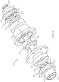
- rolling seal damper assembly 68 will vary among embodiments. Hoewver, by way of non-limiting example, additional description of rolling seal damper assembly 68 will now be provided in conjunction with FIGs. 3 and 4 , as well as the exploded view of damper assembly 68 shown in FIG. 5 .
- rolling seal damper assembly 68 includes the following static components: (i) a first diaphragm seal clamp 88, (ii) a first damper housing assembly piece 90, (iii) a second damper housing assembly piece 92, (iv) a second diaphragm seal clamp 94, (v) a first bushing 96, and (vi) a second bushing 98. Progressing from left to right in FIGs.
- the translating or movable components of damper assembly 68 include: (vii) a translating TC piston 100, (viii) a first translating seal plate 102, (ix) a translating piston structure 104, (x) a second translating seal plate 106, and (xi) a tuning spring connector piece 108.
- rolling seal damper assembly 68 also contains: (xii) a TC preload spring 110 ( FIG. 4 ), (xiii) a first rolling diaphragm seal 112, (xiv) and a second rolling diaphragm seal 114.
- rolling seal damper assembly 68 still further contains first, second, third, and fourth hydraulic chamber, as identified in FIG. 4 by reference numerals 116, 118, 120, and 122, respectively.
- Hydraulic chambers 116, 118, 120, 122 are fluidly interconnected and defined or bound by various different structural components of rolling seal damper assembly 68. With respect to hydraulic chamber 116, in particular, chamber 116 is predominately bound or defined by first rolling diaphragm seal 112, translating seal plate 102, and interior surfaces of damper housing assembly piece 90. To a lesser extent, hydraulic chamber 116 is defined by bushing 96 and a first end portion 124 of a piston shaft 124, 126 included in translating piston structure 104. Hydraulic chamber 118 is defined by damper housing assembly piece 90, bushing 96, damper housing assembly piece 92, and translating piston structure 104.
- first end portion 124 of a piston shaft 124, 126 defines hydraulic chamber 118 to a lesser extent, while a first face of damper piston 128 further included in translating piston structure 104 defines chamber 118 to a greater extent.
- hydraulic chamber 120 is defined by damper housing assembly piece 92, bushing 98, and second end portion 126 of a piston shaft 124, 126.
- hydraulic chamber 122 is defined by damper housing assembly piece 92, bushing 98, second end portion 126 of a piston shaft 124, 126, translating seal plate 106, and rolling diaphragm seal 114.
- Hydraulic chambers 116, 118, 120, 122 are internally pressurized in the illustrated example, but may be externally pressurized in further embodiments of three parameter isolator 40.
- Hydraulic chambers 118, 120 are located on opposing sides of and are fluidly partitioned, in substantial part, by damper piston 128.
- An annulus 130 ( FIG. 4 ) having a relatively narrow radial gap width is defined by the outer circumferential surface of damper piston 128 and a radially-adjacent inner circumferential surface of damper housing assembly piece 92.
- rolling seal damper assembly 68 is a rigid volume damper assembly in the illustrated example; the term "rigid volume damper assembly,” as appearing herein, indicating that the cumulative volume of the hydraulic chambers located on opposing sides of the damper piston (e.g., piston 128) remains constant as the piston strokes along the working axis.
- damper assembly 68 may not be rigid volume damper assembly and/or hydraulic fluid exchange between hydraulic chambers 118, 120 may be permitted through one or more restricted orifices other than an annulus. Substantially unrestricted damping fluid flow is also permitted from hydraulic chamber 118 to hydraulic chambers 116, 122 through a longitudinal flow channel 132 and a number of ports 134 provided in piston shaft 124, 126.
- Hydraulic chambers 116, 118, 120, 122 are fluid-tight and are filled with a damping fluid (not shown) prior to usage of three parameter isolator 40.
- Three parameter isolator 40 may initially be produced and distributed without damping fluid, which may then be introduced into hydraulic chambers 116, 118, 120, 122 through a fill port prior to isolator operation.
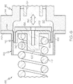
- FIG. 6 illustrates rolling diaphragm seal 112 and the surrounding structure of rolling seal damper assembly 68 in greater detail.
- rolling diaphragm seal 112 is a generally annular or ring-shaped sealing element including outer annular portion or outer peripheral flange 136, an inner annular portion or inner peripheral flange 138, and an intermediate flexible rolling section or "rolling convolute" 140.
- Outer peripheral flange 136 is captured between a flange 142 of diaphragm seal clamp 88 and a mating flange 144 of damper housing assembly piece 92, which may be joined utilized a plurality of non-illustrated fasteners.
- inner peripheral flange 148 is sealingly captured between the face of TC piston 100 and translating seal plate 102.
- Rolling convolute 140 flexes in a rolling motion to accommodate translation of TC piston 100 along working axis 46 (shown in FIG. 3 ), as indicated in FIG. 6 by double-headed arrow 150.
- TC piston 100 is movable between an extended position in which the volume of hydraulic chamber 116 is least (corresponding to the rightmost end of piston travel in FIGs. 4-6 ) and a retracted position in which the volume of hydraulic chamber 116 is greatest (corresponding to the leftmost end of piston travel).
- TC preload spring 110 is compressed between an internal wall 152 of outer housing piece 50 (identified in FIG.
- TC preload spring 110 thus urges movement of TC piston 100 (and therefore seal plate 102 and the inboard portions of seal 112) toward the extended position.
- TC piston 100, TC preload spring 110, and hydraulic chamber 116 (also referred to as a "TC chamber") form a thermal compensator, which pressurizes the hydraulic fluid contained within rolling seal damper assembly 68 (represented in FIG. 6 by dot stippling) and which provides an increased volumetric capacity (via the retraction of TC piston 100 and the rolling action of seal 112) to accommodate thermally-induced fluctuations in damping fluid volume.
- diaphragm seal clamp 88 includes an inner annular sidewall 156, while TC piston 100 includes an outer annular sidewall 158 circumscribed by inner annular sidewall 156.
- Annular sidewalls 156, 158 serve as guideways or supports, which guide movement of rolling convolute 140 as rolling diaphragm seal 112 flexes to accommodate translation of TC piston 100.
- Annular sidewalls 156, 158 also prevent the outward bulging of convolute 140 in radial directions due to the interior fluid pressure within hydraulic chamber 116.
- Rolling diaphragm seal 112 can be fabricated from any material or materials allowing seal 112 to roll or flex in conjunction with movement of TC piston 100, while sealing the sliding interface between diaphragm seal clamp 88 (and, more generally, the static structure of rolling seal damper assembly 68) and TC piston 100.
- rolling diaphragm seal 112 is fabricated from an elastic or non-elastic polymeric material, such as a nitrile rubber, which is reinforced with a fabric, such as a polyester backing.
- rolling diaphragm seal 112 may be fabricated from different materials and may have various other geometries (e.g., different flanged configurations) beyond that shown in FIGs. 4-6 .
- rolling diaphragm seal 114 is substantially identical to rolling diaphragm seal 112.
- rolling diaphragm seal 114 includes outer peripheral flange 160 (e.g., a first bolted flange), an inner peripheral flange 162 (e.g., a second bolted flange), and an intermediate rolling convolute 164, all of which are labeled in FIG. 5 .
- outer peripheral flange 160 is sealingly captured between a flange of diaphragm seal clamp 94 and the mating end of inner diameter housing assembly piece 92.
- Inner peripheral flange 162 is captured between tuning spring connector piece 108 and translating seal plate 106.
- Rolling convolute 164 contacts an outer annular sidewall 168 of diaphragm seal clamp 94 and an inner annular sidewall 170.
- sidewalls 168,170 guide the movement of rolling convolute 164 and prevent the undesired outward bulging of rolling diaphragm seal 114 when pressure loaded.
- rolling diaphragm seal 114 flexes to accommodate relative movement between tuning spring connector piece 108 (and the adjoining end of tubular spring piece 70) relative to the static structure of damper assembly 68 (and, specifically, relative to damper housing assembly piece 92 and diaphragm seal clamp 94).
- rolling diaphragm seals 112, 114 provide high integrity sealing of selected hydraulic chambers (i.e., hydraulic chambers 116, 122), while allowing low friction movement of TC piston 100 and damper piston structure 104 along working axis 46 ( FIG. 3 ).
- Rolling diaphragm seals 112, 114 in conjunction with the other components of damper assembly 68, can provide extended, low or zero leakage operation over prolonged service periods. Additionally, rolling diaphragm seals 112, 114 may accommodate relatively broad stroke capabilities, high pressure capabilities, very low static spring rates, and long service lifespans.
- rolling seal damper assembly 68 can be manually dissembled and reassembled on an as-needed basis to, for example, facilitate maintenance and to allow interchange of damping fluids. While providing a number of advantages relative to other types of sealing elements, rolling diaphragm seals 112,114 provide relatively little, if any lateral stiffness. Damper assembly 68 may therefore be further equipped with a lateral guide system, which guides movement of piston structure 104 during operation of isolator 40.
- three parameter isolator 40 may be further equipped with a linear guide system, which prevents or at least significantly deters undesired, off-axis movement of piston structure 104; that is, displacement and rotation of main spring 64 along the lateral axes (the Y- and Z-axes in coordinate legend 48) orthogonal to working axis 46 ( FIG. 3 ).
- the linear guide system may also likewise help guide the movement of main spring 64 by further restricting the motion of these components to axial movement along working axis 46 ( FIG. 3 ).
- the linear guide system is realized through two sliding interfaces.
- the first sliding interface is formed between end portion 124 of piston shaft 124, 126, and bushing 96.
- Bushing 96 and, more generally, the first sliding interface is located between rolling diaphragm seal 112 and a first face of damper piston 128, as taken along working axis 46 ( FIG. 3 ).
- the second sliding interface is formed between opposing end portion 126 of piston shaft 124, 126 and bushing 98.
- Bushing 98 and, more generally, the second sliding interface is thus located between rolling diaphragm seal a second, opposing face of damper piston 128 and rolling diaphragm seal 114, as taken along working axis 46 ( FIG. 3 ).
- the sliding interfaces forming the linear guide system are located on opposing sides of damper piston 128 and between rolling diaphragm seals 112, 114, as taken along working axis 46 ( FIG. 3 ).
- the sliding interfaces thus restrict linear movement of damper piston structure 104 and, therefore, damper piston 128 along axis perpendicular to working axis 46 ( FIG. 3 ).
- the sliding interfaces may also include keys and keyways or similar features to restrict rotation of piston structure 104 around working axis 46; however, this is not necessary.
- bushings 96, 98 are considered bearings (in particular, plane bearings), which circumscribe the opposing end portions of piston shaft 124, 126.
- bushings 96, 98 can be replaced by another type of bearing, such as rolling element bearings in the form of ball bearings or roller bearings.
- exemplary vibration isolator 40 is a three parameter device, which provides the desirable vibration attenuation characteristics described above; e.g., a relatively low peak transmissibility and superior attenuation of high frequency vibrations.
- K A is the axial stiffness of three parameter isolator 40, as a whole, which is predominately determined by the axial stiffness of main spring 64;
- K B is the volumetric stiffness of isolator 40, which is predominately determined by the axial stiffness of tuning spring 66;
- C A is determined by the damping characteristics of rolling seal damper assembly 68.
- main spring 64 (K A ) is coupled in parallel with tuning spring 66 (K B ) and rolling seal damper assembly 68 (C A ), which are coupled in series, as taken along a load transfer path extending through isolator 40.
- a first or outer vibration transmission path is provided through isolator 40 progressing from isolator end 42, through outer housing piece 50, through outer housing piece 54 including through main spring 64, and to isolator end portion 44.
- a second or inner vibration transmission path is further provided through isolator 40 progressing from isolator end 42, through outer housing piece 52, through damper assembly 68, through tuning spring connector piece 108, through tubular spring piece 70 and tuning spring 66, and to isolator end portion 44.
- the rolling seal damper assembly contains flexible rolling diaphragm seals, which seal hydraulic compartments or chambers included within the damper assembly.
- the rolling diaphragm seals may assume the form of, for example, substantially annular structures composed of a fiber-reinforced polymeric material and including rolling convolutes, which contact annular guide walls provided on selected components of the damper assembly.
- the rolling seal damper assembly may also contain a thermal compensator piston, which is sealingly attached to one of the rolling diagram seals; and/or a linear guide system, which confines off-axis movement of a damper piston structure to which at least one of the rolling diaphragm seals is sealingly attached.
- a thermal compensator piston which is sealingly attached to one of the rolling diagram seals
- a linear guide system which confines off-axis movement of a damper piston structure to which at least one of the rolling diaphragm seals is sealingly attached.
- embodiments of the three parameter isolator can be produced at lower manufacturing costs and with greater efficiency.
- embodiments of the three parameter isolator may provide reliable, substantially frictionless, high temperature range, low to zero leakage operation, while facilitating isolator disassembly.
Landscapes
- Engineering & Computer Science (AREA)
- General Engineering & Computer Science (AREA)
- Mechanical Engineering (AREA)
- Aviation & Aerospace Engineering (AREA)
- Physics & Mathematics (AREA)
- Acoustics & Sound (AREA)
- Remote Sensing (AREA)
- Vibration Prevention Devices (AREA)
- Fluid-Damping Devices (AREA)
Applications Claiming Priority (1)
| Application Number | Priority Date | Filing Date | Title |
|---|---|---|---|
| US15/412,525 US10066697B2 (en) | 2017-01-23 | 2017-01-23 | Three parameter isolators containing rolling seal damper assemblies |
Publications (2)
| Publication Number | Publication Date |
|---|---|
| EP3354930A1 true EP3354930A1 (fr) | 2018-08-01 |
| EP3354930B1 EP3354930B1 (fr) | 2019-06-19 |
Family
ID=61027467
Family Applications (1)
| Application Number | Title | Priority Date | Filing Date |
|---|---|---|---|
| EP18152853.0A Active EP3354930B1 (fr) | 2017-01-23 | 2018-01-22 | Isolateurs à trois paramètres contenant des ensembles amortisseurs comprenant une membrane déroulante |
Country Status (3)
| Country | Link |
|---|---|
| US (1) | US10066697B2 (fr) |
| EP (1) | EP3354930B1 (fr) |
| JP (1) | JP7027173B2 (fr) |
Cited By (1)
| Publication number | Priority date | Publication date | Assignee | Title |
|---|---|---|---|---|
| CN111120568A (zh) * | 2020-02-11 | 2020-05-08 | 焦彪彪 | 一种气液串联变阻尼减震器 |
Families Citing this family (3)
| Publication number | Priority date | Publication date | Assignee | Title |
|---|---|---|---|---|
| US12215752B1 (en) | 2019-07-30 | 2025-02-04 | Blue Canyon Technologies LLC | Vibration isolator with overload protection |
| CN114476145B (zh) * | 2022-01-18 | 2022-10-04 | 大连理工大学 | 短切碳纤维增强热塑性复合材料的卫星隔/减振支架 |
| DE102024208612A1 (de) * | 2024-09-10 | 2026-03-12 | Carl Zeiss Smt Gmbh | Optisches system, lithographieanlage, verfahren zur herstellung eines optischen systems, und verfahren zum auslegen eines schwingungsdämpfers eines optischen systems |
Citations (7)
| Publication number | Priority date | Publication date | Assignee | Title |
|---|---|---|---|---|
| US3266603A (en) * | 1965-02-24 | 1966-08-16 | Michael M Kamimoto | Extreme environment hermetically sealed damper |
| US5332070A (en) | 1993-04-21 | 1994-07-26 | Honeywell Inc. | Three parameter viscous damper and isolator |
| JP3237962B2 (ja) * | 1993-06-14 | 2001-12-10 | 不二精器株式会社 | ショックアブソーバ |
| US7182188B2 (en) | 2005-02-16 | 2007-02-27 | Honeywell International, Inc. | Isolator using externally pressurized sealing bellows |
| EP2801734A1 (fr) * | 2013-04-17 | 2014-11-12 | Honeywell International Inc. | Isolateurs comprenant des ensembles d'amortisseur présentant des anneaux variables et systèmes d'isolation de vaisseau spatial employant ceux-ci |
| EP2876327A2 (fr) * | 2013-11-26 | 2015-05-27 | Honeywell International Inc. | Isolateur avec élèment de flexion emboité et méthode pour le produire |
| EP3121480A2 (fr) * | 2015-07-23 | 2017-01-25 | Honeywell International Inc. | Isolateurs comprenant des systèmes de guidage linéaire pour ressort principal |
Family Cites Families (18)
| Publication number | Priority date | Publication date | Assignee | Title |
|---|---|---|---|---|
| US2720218A (en) | 1951-03-29 | 1955-10-11 | Johnson Service Co | Fluid pressure operated dampers of the dual type |
| DE1924293B2 (de) | 1969-05-13 | 1972-01-27 | Demag Ag, 4100 Duisburg | Saugkopf fuer feste koerper |
| US3730473A (en) | 1970-03-19 | 1973-05-01 | Barry Wright Co | Pneumatic self-positioning shock and vibration isolation stabilizing absorber |
| US4022448A (en) | 1975-12-05 | 1977-05-10 | Lehan James Reeder | Vehicle suspension unit and method of assembly thereof |
| US4655438A (en) | 1985-12-23 | 1987-04-07 | General Motors Corporation | Hydraulically damped dual sleeve air spring suspension |
| JPH04219536A (ja) | 1990-09-25 | 1992-08-10 | Bridgestone Corp | 振動減衰装置 |
| US5318156A (en) | 1992-12-15 | 1994-06-07 | Honeywell Inc. | Rigid volume viscous damper |
| JPH07119779A (ja) * | 1993-10-28 | 1995-05-09 | Bridgestone Corp | 振動減衰装置 |
| JPH0874915A (ja) * | 1994-09-02 | 1996-03-19 | Fujikura Rubber Ltd | 減衰装置 |
| DE50010763D1 (de) | 1999-08-24 | 2005-08-25 | Contitech Luftfedersyst Gmbh | Feder-dämpfersystem mit differenzrollbalg |
| US6848980B2 (en) | 2001-10-10 | 2005-02-01 | Applied Materials, Inc. | Vibration damping in a carrier head |
| DE102004059764C5 (de) * | 2004-12-11 | 2013-06-06 | Continental Teves Ag & Co. Ohg | Luftfeder- und Dämpfereinheit |
| DE102004059765A1 (de) * | 2004-12-11 | 2006-07-06 | Continental Aktiengesellschaft | Radführende Luftfeder- und Dämpfereinheit |
| US9068554B2 (en) | 2009-06-09 | 2015-06-30 | James W. Healy | Wave energy electrical power generation |
| JP5414642B2 (ja) | 2010-09-10 | 2014-02-12 | 三菱電機株式会社 | 振動絶縁装置 |
| US8899389B2 (en) | 2011-05-19 | 2014-12-02 | Honeywell International Inc. | Thermally-conductive vibration isolators and spacecraft isolation systems employing the same |
| US9416842B2 (en) | 2013-03-27 | 2016-08-16 | Honeywell International Inc. | Isolators having damper-external thermal compensators and spacecraft isolation systems employing the same |
| US9453552B2 (en) * | 2014-07-14 | 2016-09-27 | Honeywell International Inc. | Adaptive three parameter isolator assemblies including external magneto-rheological valves |
-
2017
- 2017-01-23 US US15/412,525 patent/US10066697B2/en active Active
-
2018
- 2018-01-12 JP JP2018003318A patent/JP7027173B2/ja active Active
- 2018-01-22 EP EP18152853.0A patent/EP3354930B1/fr active Active
Patent Citations (7)
| Publication number | Priority date | Publication date | Assignee | Title |
|---|---|---|---|---|
| US3266603A (en) * | 1965-02-24 | 1966-08-16 | Michael M Kamimoto | Extreme environment hermetically sealed damper |
| US5332070A (en) | 1993-04-21 | 1994-07-26 | Honeywell Inc. | Three parameter viscous damper and isolator |
| JP3237962B2 (ja) * | 1993-06-14 | 2001-12-10 | 不二精器株式会社 | ショックアブソーバ |
| US7182188B2 (en) | 2005-02-16 | 2007-02-27 | Honeywell International, Inc. | Isolator using externally pressurized sealing bellows |
| EP2801734A1 (fr) * | 2013-04-17 | 2014-11-12 | Honeywell International Inc. | Isolateurs comprenant des ensembles d'amortisseur présentant des anneaux variables et systèmes d'isolation de vaisseau spatial employant ceux-ci |
| EP2876327A2 (fr) * | 2013-11-26 | 2015-05-27 | Honeywell International Inc. | Isolateur avec élèment de flexion emboité et méthode pour le produire |
| EP3121480A2 (fr) * | 2015-07-23 | 2017-01-25 | Honeywell International Inc. | Isolateurs comprenant des systèmes de guidage linéaire pour ressort principal |
Cited By (1)
| Publication number | Priority date | Publication date | Assignee | Title |
|---|---|---|---|---|
| CN111120568A (zh) * | 2020-02-11 | 2020-05-08 | 焦彪彪 | 一种气液串联变阻尼减震器 |
Also Published As
| Publication number | Publication date |
|---|---|
| US10066697B2 (en) | 2018-09-04 |
| US20180209508A1 (en) | 2018-07-26 |
| EP3354930B1 (fr) | 2019-06-19 |
| JP2018119678A (ja) | 2018-08-02 |
| JP7027173B2 (ja) | 2022-03-01 |
Similar Documents
| Publication | Publication Date | Title |
|---|---|---|
| EP3354930B1 (fr) | Isolateurs à trois paramètres contenant des ensembles amortisseurs comprenant une membrane déroulante | |
| EP2518366B1 (fr) | Isolateurs multi-axes à trois paramètres | |
| EP1848899B1 (fr) | Isolateur ameliore utilisant des soufflets d'etancheite pressurises exterieurement | |
| US6431530B1 (en) | Vertical liquid inertia vibration isolator | |
| US9416842B2 (en) | Isolators having damper-external thermal compensators and spacecraft isolation systems employing the same | |
| US8888079B2 (en) | Apparatus for improved vibration isolation | |
| EP2607240A2 (fr) | Dispositifs d'isolation passive pour amortissement de fréquence basse de charges utiles de faible masse et systèmes d'isolation d'engin spatial employant celui-ci | |
| US9670983B2 (en) | Isolators including damper assemblies having variable annuli and spacecraft isolation systems employing the same | |
| US11787552B2 (en) | Engine mount system and elements for reduced force transmission and reduced static motion | |
| EP3121480B1 (fr) | Isolateurs comprenant des systèmes de guidage linéaire pour ressort principal | |
| EP1203898B1 (fr) | Arrangement fluidique et élastomérique avec compensateur de volume discret et seconde unité d'adaptation | |
| CA2606976C (fr) | Accumulateur a clapet antiretour precharge |
Legal Events
| Date | Code | Title | Description |
|---|---|---|---|
| PUAI | Public reference made under article 153(3) epc to a published international application that has entered the european phase |
Free format text: ORIGINAL CODE: 0009012 |
|
| STAA | Information on the status of an ep patent application or granted ep patent |
Free format text: STATUS: REQUEST FOR EXAMINATION WAS MADE |
|
| 17P | Request for examination filed |
Effective date: 20180122 |
|
| AK | Designated contracting states |
Kind code of ref document: A1 Designated state(s): AL AT BE BG CH CY CZ DE DK EE ES FI FR GB GR HR HU IE IS IT LI LT LU LV MC MK MT NL NO PL PT RO RS SE SI SK SM TR |
|
| AX | Request for extension of the european patent |
Extension state: BA ME |
|
| RIC1 | Information provided on ipc code assigned before grant |
Ipc: F16F 9/20 20060101ALI20181119BHEP Ipc: F16F 15/023 20060101AFI20181119BHEP Ipc: B64G 1/22 20060101ALI20181119BHEP |
|
| GRAP | Despatch of communication of intention to grant a patent |
Free format text: ORIGINAL CODE: EPIDOSNIGR1 |
|
| STAA | Information on the status of an ep patent application or granted ep patent |
Free format text: STATUS: GRANT OF PATENT IS INTENDED |
|
| INTG | Intention to grant announced |
Effective date: 20190102 |
|
| RIN1 | Information on inventor provided before grant (corrected) |
Inventor name: HINDLE, TIMOTHY Inventor name: JAKSICH, DYLAN Inventor name: BARBER, TIM DANIEL |
|
| GRAS | Grant fee paid |
Free format text: ORIGINAL CODE: EPIDOSNIGR3 |
|
| GRAA | (expected) grant |
Free format text: ORIGINAL CODE: 0009210 |
|
| STAA | Information on the status of an ep patent application or granted ep patent |
Free format text: STATUS: THE PATENT HAS BEEN GRANTED |
|
| AK | Designated contracting states |
Kind code of ref document: B1 Designated state(s): AL AT BE BG CH CY CZ DE DK EE ES FI FR GB GR HR HU IE IS IT LI LT LU LV MC MK MT NL NO PL PT RO RS SE SI SK SM TR |
|
| REG | Reference to a national code |
Ref country code: GB Ref legal event code: FG4D |
|
| REG | Reference to a national code |
Ref country code: CH Ref legal event code: EP |
|
| REG | Reference to a national code |
Ref country code: IE Ref legal event code: FG4D |
|
| REG | Reference to a national code |
Ref country code: AT Ref legal event code: REF Ref document number: 1145920 Country of ref document: AT Kind code of ref document: T Effective date: 20190715 |
|
| REG | Reference to a national code |
Ref country code: DE Ref legal event code: R096 Ref document number: 602018000143 Country of ref document: DE |
|
| REG | Reference to a national code |
Ref country code: NL Ref legal event code: MP Effective date: 20190619 |
|
| PG25 | Lapsed in a contracting state [announced via postgrant information from national office to epo] |
Ref country code: LT Free format text: LAPSE BECAUSE OF FAILURE TO SUBMIT A TRANSLATION OF THE DESCRIPTION OR TO PAY THE FEE WITHIN THE PRESCRIBED TIME-LIMIT Effective date: 20190619 Ref country code: HR Free format text: LAPSE BECAUSE OF FAILURE TO SUBMIT A TRANSLATION OF THE DESCRIPTION OR TO PAY THE FEE WITHIN THE PRESCRIBED TIME-LIMIT Effective date: 20190619 Ref country code: SE Free format text: LAPSE BECAUSE OF FAILURE TO SUBMIT A TRANSLATION OF THE DESCRIPTION OR TO PAY THE FEE WITHIN THE PRESCRIBED TIME-LIMIT Effective date: 20190619 Ref country code: NO Free format text: LAPSE BECAUSE OF FAILURE TO SUBMIT A TRANSLATION OF THE DESCRIPTION OR TO PAY THE FEE WITHIN THE PRESCRIBED TIME-LIMIT Effective date: 20190919 Ref country code: AL Free format text: LAPSE BECAUSE OF FAILURE TO SUBMIT A TRANSLATION OF THE DESCRIPTION OR TO PAY THE FEE WITHIN THE PRESCRIBED TIME-LIMIT Effective date: 20190619 Ref country code: FI Free format text: LAPSE BECAUSE OF FAILURE TO SUBMIT A TRANSLATION OF THE DESCRIPTION OR TO PAY THE FEE WITHIN THE PRESCRIBED TIME-LIMIT Effective date: 20190619 |
|
| REG | Reference to a national code |
Ref country code: LT Ref legal event code: MG4D |
|
| PG25 | Lapsed in a contracting state [announced via postgrant information from national office to epo] |
Ref country code: BG Free format text: LAPSE BECAUSE OF FAILURE TO SUBMIT A TRANSLATION OF THE DESCRIPTION OR TO PAY THE FEE WITHIN THE PRESCRIBED TIME-LIMIT Effective date: 20190919 Ref country code: LV Free format text: LAPSE BECAUSE OF FAILURE TO SUBMIT A TRANSLATION OF THE DESCRIPTION OR TO PAY THE FEE WITHIN THE PRESCRIBED TIME-LIMIT Effective date: 20190619 Ref country code: RS Free format text: LAPSE BECAUSE OF FAILURE TO SUBMIT A TRANSLATION OF THE DESCRIPTION OR TO PAY THE FEE WITHIN THE PRESCRIBED TIME-LIMIT Effective date: 20190619 Ref country code: GR Free format text: LAPSE BECAUSE OF FAILURE TO SUBMIT A TRANSLATION OF THE DESCRIPTION OR TO PAY THE FEE WITHIN THE PRESCRIBED TIME-LIMIT Effective date: 20190920 |
|
| REG | Reference to a national code |
Ref country code: AT Ref legal event code: MK05 Ref document number: 1145920 Country of ref document: AT Kind code of ref document: T Effective date: 20190619 |
|
| PG25 | Lapsed in a contracting state [announced via postgrant information from national office to epo] |
Ref country code: SK Free format text: LAPSE BECAUSE OF FAILURE TO SUBMIT A TRANSLATION OF THE DESCRIPTION OR TO PAY THE FEE WITHIN THE PRESCRIBED TIME-LIMIT Effective date: 20190619 Ref country code: RO Free format text: LAPSE BECAUSE OF FAILURE TO SUBMIT A TRANSLATION OF THE DESCRIPTION OR TO PAY THE FEE WITHIN THE PRESCRIBED TIME-LIMIT Effective date: 20190619 Ref country code: NL Free format text: LAPSE BECAUSE OF FAILURE TO SUBMIT A TRANSLATION OF THE DESCRIPTION OR TO PAY THE FEE WITHIN THE PRESCRIBED TIME-LIMIT Effective date: 20190619 Ref country code: CZ Free format text: LAPSE BECAUSE OF FAILURE TO SUBMIT A TRANSLATION OF THE DESCRIPTION OR TO PAY THE FEE WITHIN THE PRESCRIBED TIME-LIMIT Effective date: 20190619 Ref country code: AT Free format text: LAPSE BECAUSE OF FAILURE TO SUBMIT A TRANSLATION OF THE DESCRIPTION OR TO PAY THE FEE WITHIN THE PRESCRIBED TIME-LIMIT Effective date: 20190619 Ref country code: EE Free format text: LAPSE BECAUSE OF FAILURE TO SUBMIT A TRANSLATION OF THE DESCRIPTION OR TO PAY THE FEE WITHIN THE PRESCRIBED TIME-LIMIT Effective date: 20190619 Ref country code: PT Free format text: LAPSE BECAUSE OF FAILURE TO SUBMIT A TRANSLATION OF THE DESCRIPTION OR TO PAY THE FEE WITHIN THE PRESCRIBED TIME-LIMIT Effective date: 20191021 |
|
| PG25 | Lapsed in a contracting state [announced via postgrant information from national office to epo] |
Ref country code: SM Free format text: LAPSE BECAUSE OF FAILURE TO SUBMIT A TRANSLATION OF THE DESCRIPTION OR TO PAY THE FEE WITHIN THE PRESCRIBED TIME-LIMIT Effective date: 20190619 Ref country code: IS Free format text: LAPSE BECAUSE OF FAILURE TO SUBMIT A TRANSLATION OF THE DESCRIPTION OR TO PAY THE FEE WITHIN THE PRESCRIBED TIME-LIMIT Effective date: 20191019 Ref country code: IT Free format text: LAPSE BECAUSE OF FAILURE TO SUBMIT A TRANSLATION OF THE DESCRIPTION OR TO PAY THE FEE WITHIN THE PRESCRIBED TIME-LIMIT Effective date: 20190619 Ref country code: ES Free format text: LAPSE BECAUSE OF FAILURE TO SUBMIT A TRANSLATION OF THE DESCRIPTION OR TO PAY THE FEE WITHIN THE PRESCRIBED TIME-LIMIT Effective date: 20190619 |
|
| PG25 | Lapsed in a contracting state [announced via postgrant information from national office to epo] |
Ref country code: TR Free format text: LAPSE BECAUSE OF FAILURE TO SUBMIT A TRANSLATION OF THE DESCRIPTION OR TO PAY THE FEE WITHIN THE PRESCRIBED TIME-LIMIT Effective date: 20190619 |
|
| PG25 | Lapsed in a contracting state [announced via postgrant information from national office to epo] |
Ref country code: PL Free format text: LAPSE BECAUSE OF FAILURE TO SUBMIT A TRANSLATION OF THE DESCRIPTION OR TO PAY THE FEE WITHIN THE PRESCRIBED TIME-LIMIT Effective date: 20190619 Ref country code: DK Free format text: LAPSE BECAUSE OF FAILURE TO SUBMIT A TRANSLATION OF THE DESCRIPTION OR TO PAY THE FEE WITHIN THE PRESCRIBED TIME-LIMIT Effective date: 20190619 |
|
| PG25 | Lapsed in a contracting state [announced via postgrant information from national office to epo] |
Ref country code: IS Free format text: LAPSE BECAUSE OF FAILURE TO SUBMIT A TRANSLATION OF THE DESCRIPTION OR TO PAY THE FEE WITHIN THE PRESCRIBED TIME-LIMIT Effective date: 20200224 |
|
| REG | Reference to a national code |
Ref country code: DE Ref legal event code: R097 Ref document number: 602018000143 Country of ref document: DE |
|
| PLBE | No opposition filed within time limit |
Free format text: ORIGINAL CODE: 0009261 |
|
| STAA | Information on the status of an ep patent application or granted ep patent |
Free format text: STATUS: NO OPPOSITION FILED WITHIN TIME LIMIT |
|
| PG2D | Information on lapse in contracting state deleted |
Ref country code: IS |
|
| 26N | No opposition filed |
Effective date: 20200603 |
|
| PG25 | Lapsed in a contracting state [announced via postgrant information from national office to epo] |
Ref country code: SI Free format text: LAPSE BECAUSE OF FAILURE TO SUBMIT A TRANSLATION OF THE DESCRIPTION OR TO PAY THE FEE WITHIN THE PRESCRIBED TIME-LIMIT Effective date: 20190619 Ref country code: MC Free format text: LAPSE BECAUSE OF FAILURE TO SUBMIT A TRANSLATION OF THE DESCRIPTION OR TO PAY THE FEE WITHIN THE PRESCRIBED TIME-LIMIT Effective date: 20190619 |
|
| REG | Reference to a national code |
Ref country code: BE Ref legal event code: MM Effective date: 20200131 |
|
| PG25 | Lapsed in a contracting state [announced via postgrant information from national office to epo] |
Ref country code: LU Free format text: LAPSE BECAUSE OF NON-PAYMENT OF DUE FEES Effective date: 20200122 |
|
| PG25 | Lapsed in a contracting state [announced via postgrant information from national office to epo] |
Ref country code: BE Free format text: LAPSE BECAUSE OF NON-PAYMENT OF DUE FEES Effective date: 20200131 |
|
| PG25 | Lapsed in a contracting state [announced via postgrant information from national office to epo] |
Ref country code: IE Free format text: LAPSE BECAUSE OF NON-PAYMENT OF DUE FEES Effective date: 20200122 |
|
| REG | Reference to a national code |
Ref country code: CH Ref legal event code: PL |
|
| PG25 | Lapsed in a contracting state [announced via postgrant information from national office to epo] |
Ref country code: LI Free format text: LAPSE BECAUSE OF NON-PAYMENT OF DUE FEES Effective date: 20210131 Ref country code: CH Free format text: LAPSE BECAUSE OF NON-PAYMENT OF DUE FEES Effective date: 20210131 |
|
| PGFP | Annual fee paid to national office [announced via postgrant information from national office to epo] |
Ref country code: DE Payment date: 20220127 Year of fee payment: 5 |
|
| PG25 | Lapsed in a contracting state [announced via postgrant information from national office to epo] |
Ref country code: MT Free format text: LAPSE BECAUSE OF FAILURE TO SUBMIT A TRANSLATION OF THE DESCRIPTION OR TO PAY THE FEE WITHIN THE PRESCRIBED TIME-LIMIT Effective date: 20190619 Ref country code: CY Free format text: LAPSE BECAUSE OF FAILURE TO SUBMIT A TRANSLATION OF THE DESCRIPTION OR TO PAY THE FEE WITHIN THE PRESCRIBED TIME-LIMIT Effective date: 20190619 |
|
| PG25 | Lapsed in a contracting state [announced via postgrant information from national office to epo] |
Ref country code: MK Free format text: LAPSE BECAUSE OF FAILURE TO SUBMIT A TRANSLATION OF THE DESCRIPTION OR TO PAY THE FEE WITHIN THE PRESCRIBED TIME-LIMIT Effective date: 20190619 |
|
| GBPC | Gb: european patent ceased through non-payment of renewal fee |
Effective date: 20220122 |
|
| PG25 | Lapsed in a contracting state [announced via postgrant information from national office to epo] |
Ref country code: GB Free format text: LAPSE BECAUSE OF NON-PAYMENT OF DUE FEES Effective date: 20220122 |
|
| P01 | Opt-out of the competence of the unified patent court (upc) registered |
Effective date: 20230525 |
|
| REG | Reference to a national code |
Ref country code: DE Ref legal event code: R119 Ref document number: 602018000143 Country of ref document: DE |
|
| PG25 | Lapsed in a contracting state [announced via postgrant information from national office to epo] |
Ref country code: DE Free format text: LAPSE BECAUSE OF NON-PAYMENT OF DUE FEES Effective date: 20230801 |
|
| PGFP | Annual fee paid to national office [announced via postgrant information from national office to epo] |
Ref country code: FR Payment date: 20260127 Year of fee payment: 9 |