EP3354937A1 - Kart et ensemble d'entraînement pour kart - Google Patents
Kart et ensemble d'entraînement pour kart Download PDFInfo
- Publication number
- EP3354937A1 EP3354937A1 EP18154095.6A EP18154095A EP3354937A1 EP 3354937 A1 EP3354937 A1 EP 3354937A1 EP 18154095 A EP18154095 A EP 18154095A EP 3354937 A1 EP3354937 A1 EP 3354937A1
- Authority
- EP
- European Patent Office
- Prior art keywords
- housing
- panel
- assembly
- disposed
- assembly housing
- Prior art date
- Legal status (The legal status is an assumption and is not a legal conclusion. Google has not performed a legal analysis and makes no representation as to the accuracy of the status listed.)
- Granted
Links
Images






Classifications
-
- B—PERFORMING OPERATIONS; TRANSPORTING
- B60—VEHICLES IN GENERAL
- B60K—ARRANGEMENT OR MOUNTING OF PROPULSION UNITS OR OF TRANSMISSIONS IN VEHICLES; ARRANGEMENT OR MOUNTING OF PLURAL DIVERSE PRIME-MOVERS IN VEHICLES; AUXILIARY DRIVES FOR VEHICLES; INSTRUMENTATION OR DASHBOARDS FOR VEHICLES; ARRANGEMENTS IN CONNECTION WITH COOLING, AIR INTAKE, GAS EXHAUST OR FUEL SUPPLY OF PROPULSION UNITS IN VEHICLES
- B60K17/00—Arrangement or mounting of transmissions in vehicles
- B60K17/04—Arrangement or mounting of transmissions in vehicles characterised by arrangement, location or kind of gearing
-
- B—PERFORMING OPERATIONS; TRANSPORTING
- B60—VEHICLES IN GENERAL
- B60K—ARRANGEMENT OR MOUNTING OF PROPULSION UNITS OR OF TRANSMISSIONS IN VEHICLES; ARRANGEMENT OR MOUNTING OF PLURAL DIVERSE PRIME-MOVERS IN VEHICLES; AUXILIARY DRIVES FOR VEHICLES; INSTRUMENTATION OR DASHBOARDS FOR VEHICLES; ARRANGEMENTS IN CONNECTION WITH COOLING, AIR INTAKE, GAS EXHAUST OR FUEL SUPPLY OF PROPULSION UNITS IN VEHICLES
- B60K17/00—Arrangement or mounting of transmissions in vehicles
- B60K17/04—Arrangement or mounting of transmissions in vehicles characterised by arrangement, location or kind of gearing
- B60K17/06—Arrangement or mounting of transmissions in vehicles characterised by arrangement, location or kind of gearing of change-speed gearing
- B60K17/08—Arrangement or mounting of transmissions in vehicles characterised by arrangement, location or kind of gearing of change-speed gearing of mechanical type
-
- B—PERFORMING OPERATIONS; TRANSPORTING
- B60—VEHICLES IN GENERAL
- B60K—ARRANGEMENT OR MOUNTING OF PROPULSION UNITS OR OF TRANSMISSIONS IN VEHICLES; ARRANGEMENT OR MOUNTING OF PLURAL DIVERSE PRIME-MOVERS IN VEHICLES; AUXILIARY DRIVES FOR VEHICLES; INSTRUMENTATION OR DASHBOARDS FOR VEHICLES; ARRANGEMENTS IN CONNECTION WITH COOLING, AIR INTAKE, GAS EXHAUST OR FUEL SUPPLY OF PROPULSION UNITS IN VEHICLES
- B60K1/00—Arrangement or mounting of electrical propulsion units
-
- B—PERFORMING OPERATIONS; TRANSPORTING
- B60—VEHICLES IN GENERAL
- B60K—ARRANGEMENT OR MOUNTING OF PROPULSION UNITS OR OF TRANSMISSIONS IN VEHICLES; ARRANGEMENT OR MOUNTING OF PLURAL DIVERSE PRIME-MOVERS IN VEHICLES; AUXILIARY DRIVES FOR VEHICLES; INSTRUMENTATION OR DASHBOARDS FOR VEHICLES; ARRANGEMENTS IN CONNECTION WITH COOLING, AIR INTAKE, GAS EXHAUST OR FUEL SUPPLY OF PROPULSION UNITS IN VEHICLES
- B60K17/00—Arrangement or mounting of transmissions in vehicles
- B60K17/22—Arrangement or mounting of transmissions in vehicles characterised by arrangement, location, or type of main drive shafting, e.g. cardan shaft
-
- F—MECHANICAL ENGINEERING; LIGHTING; HEATING; WEAPONS; BLASTING
- F16—ENGINEERING ELEMENTS AND UNITS; GENERAL MEASURES FOR PRODUCING AND MAINTAINING EFFECTIVE FUNCTIONING OF MACHINES OR INSTALLATIONS; THERMAL INSULATION IN GENERAL
- F16H—GEARING
- F16H1/00—Toothed gearings for conveying rotary motion
- F16H1/02—Toothed gearings for conveying rotary motion without gears having orbital motion
- F16H1/20—Toothed gearings for conveying rotary motion without gears having orbital motion involving more than two intermeshing members
-
- F—MECHANICAL ENGINEERING; LIGHTING; HEATING; WEAPONS; BLASTING
- F16—ENGINEERING ELEMENTS AND UNITS; GENERAL MEASURES FOR PRODUCING AND MAINTAINING EFFECTIVE FUNCTIONING OF MACHINES OR INSTALLATIONS; THERMAL INSULATION IN GENERAL
- F16H—GEARING
- F16H57/00—General details of gearing
- F16H57/02—Gearboxes; Mounting gearing therein
-
- F—MECHANICAL ENGINEERING; LIGHTING; HEATING; WEAPONS; BLASTING
- F16—ENGINEERING ELEMENTS AND UNITS; GENERAL MEASURES FOR PRODUCING AND MAINTAINING EFFECTIVE FUNCTIONING OF MACHINES OR INSTALLATIONS; THERMAL INSULATION IN GENERAL
- F16H—GEARING
- F16H57/00—General details of gearing
- F16H57/02—Gearboxes; Mounting gearing therein
- F16H57/021—Shaft support structures, e.g. partition walls, bearing eyes, casing walls or covers with bearings
-
- F—MECHANICAL ENGINEERING; LIGHTING; HEATING; WEAPONS; BLASTING
- F16—ENGINEERING ELEMENTS AND UNITS; GENERAL MEASURES FOR PRODUCING AND MAINTAINING EFFECTIVE FUNCTIONING OF MACHINES OR INSTALLATIONS; THERMAL INSULATION IN GENERAL
- F16H—GEARING
- F16H57/00—General details of gearing
- F16H57/02—Gearboxes; Mounting gearing therein
- F16H57/023—Mounting or installation of gears or shafts in the gearboxes, e.g. methods or means for assembly
-
- F—MECHANICAL ENGINEERING; LIGHTING; HEATING; WEAPONS; BLASTING
- F16—ENGINEERING ELEMENTS AND UNITS; GENERAL MEASURES FOR PRODUCING AND MAINTAINING EFFECTIVE FUNCTIONING OF MACHINES OR INSTALLATIONS; THERMAL INSULATION IN GENERAL
- F16H—GEARING
- F16H57/00—General details of gearing
- F16H57/02—Gearboxes; Mounting gearing therein
- F16H57/031—Gearboxes; Mounting gearing therein characterised by covers or lids for gearboxes
-
- F—MECHANICAL ENGINEERING; LIGHTING; HEATING; WEAPONS; BLASTING
- F16—ENGINEERING ELEMENTS AND UNITS; GENERAL MEASURES FOR PRODUCING AND MAINTAINING EFFECTIVE FUNCTIONING OF MACHINES OR INSTALLATIONS; THERMAL INSULATION IN GENERAL
- F16H—GEARING
- F16H57/00—General details of gearing
- F16H57/04—Features relating to lubrication or cooling or heating
-
- F—MECHANICAL ENGINEERING; LIGHTING; HEATING; WEAPONS; BLASTING
- F16—ENGINEERING ELEMENTS AND UNITS; GENERAL MEASURES FOR PRODUCING AND MAINTAINING EFFECTIVE FUNCTIONING OF MACHINES OR INSTALLATIONS; THERMAL INSULATION IN GENERAL
- F16H—GEARING
- F16H57/00—General details of gearing
- F16H57/04—Features relating to lubrication or cooling or heating
- F16H57/045—Lubricant storage reservoirs, e.g. reservoirs in addition to a gear sump for collecting lubricant in the upper part of a gear case
- F16H57/0452—Oil pans
-
- F—MECHANICAL ENGINEERING; LIGHTING; HEATING; WEAPONS; BLASTING
- F16—ENGINEERING ELEMENTS AND UNITS; GENERAL MEASURES FOR PRODUCING AND MAINTAINING EFFECTIVE FUNCTIONING OF MACHINES OR INSTALLATIONS; THERMAL INSULATION IN GENERAL
- F16H—GEARING
- F16H57/00—General details of gearing
- F16H57/04—Features relating to lubrication or cooling or heating
- F16H57/0467—Elements of gearings to be lubricated, cooled or heated
- F16H57/0476—Electric machines and gearing, i.e. joint lubrication or cooling or heating thereof
-
- B—PERFORMING OPERATIONS; TRANSPORTING
- B60—VEHICLES IN GENERAL
- B60G—VEHICLE SUSPENSION ARRANGEMENTS
- B60G2300/00—Indexing codes relating to the type of vehicle
- B60G2300/26—Carts
-
- B—PERFORMING OPERATIONS; TRANSPORTING
- B60—VEHICLES IN GENERAL
- B60K—ARRANGEMENT OR MOUNTING OF PROPULSION UNITS OR OF TRANSMISSIONS IN VEHICLES; ARRANGEMENT OR MOUNTING OF PLURAL DIVERSE PRIME-MOVERS IN VEHICLES; AUXILIARY DRIVES FOR VEHICLES; INSTRUMENTATION OR DASHBOARDS FOR VEHICLES; ARRANGEMENTS IN CONNECTION WITH COOLING, AIR INTAKE, GAS EXHAUST OR FUEL SUPPLY OF PROPULSION UNITS IN VEHICLES
- B60K1/00—Arrangement or mounting of electrical propulsion units
- B60K2001/001—Arrangement or mounting of electrical propulsion units one motor mounted on a propulsion axle for rotating right and left wheels of this axle
-
- B—PERFORMING OPERATIONS; TRANSPORTING
- B60—VEHICLES IN GENERAL
- B60L—PROPULSION OF ELECTRICALLY-PROPELLED VEHICLES; SUPPLYING ELECTRIC POWER FOR AUXILIARY EQUIPMENT OF ELECTRICALLY-PROPELLED VEHICLES; ELECTRODYNAMIC BRAKE SYSTEMS FOR VEHICLES IN GENERAL; MAGNETIC SUSPENSION OR LEVITATION FOR VEHICLES; MONITORING OPERATING VARIABLES OF ELECTRICALLY-PROPELLED VEHICLES; ELECTRIC SAFETY DEVICES FOR ELECTRICALLY-PROPELLED VEHICLES
- B60L15/00—Methods, circuits, or devices for controlling the traction-motor speed of electrically-propelled vehicles
- B60L15/007—Physical arrangements or structures of drive train converters specially adapted for the propulsion motors of electric vehicles
-
- B—PERFORMING OPERATIONS; TRANSPORTING
- B60—VEHICLES IN GENERAL
- B60Y—INDEXING SCHEME RELATING TO ASPECTS CROSS-CUTTING VEHICLE TECHNOLOGY
- B60Y2200/00—Type of vehicle
- B60Y2200/10—Road Vehicles
- B60Y2200/11—Passenger cars; Automobiles
- B60Y2200/114—Racing vehicles, e.g. Formula one, Karts
-
- B—PERFORMING OPERATIONS; TRANSPORTING
- B62—LAND VEHICLES FOR TRAVELLING OTHERWISE THAN ON RAILS
- B62D—MOTOR VEHICLES; TRAILERS
- B62D21/00—Understructures, i.e. chassis frame on which a vehicle body may be mounted
- B62D21/18—Understructures, i.e. chassis frame on which a vehicle body may be mounted characterised by the vehicle type and not provided for in groups B62D21/02 - B62D21/17
- B62D21/183—Understructures, i.e. chassis frame on which a vehicle body may be mounted characterised by the vehicle type and not provided for in groups B62D21/02 - B62D21/17 specially adapted for sports vehicles, e.g. race, dune buggies, go-karts
-
- F—MECHANICAL ENGINEERING; LIGHTING; HEATING; WEAPONS; BLASTING
- F16—ENGINEERING ELEMENTS AND UNITS; GENERAL MEASURES FOR PRODUCING AND MAINTAINING EFFECTIVE FUNCTIONING OF MACHINES OR INSTALLATIONS; THERMAL INSULATION IN GENERAL
- F16H—GEARING
- F16H57/00—General details of gearing
- F16H57/02—Gearboxes; Mounting gearing therein
- F16H2057/02034—Gearboxes combined or connected with electric machines
-
- F—MECHANICAL ENGINEERING; LIGHTING; HEATING; WEAPONS; BLASTING
- F16—ENGINEERING ELEMENTS AND UNITS; GENERAL MEASURES FOR PRODUCING AND MAINTAINING EFFECTIVE FUNCTIONING OF MACHINES OR INSTALLATIONS; THERMAL INSULATION IN GENERAL
- F16H—GEARING
- F16H57/00—General details of gearing
- F16H57/02—Gearboxes; Mounting gearing therein
- F16H2057/02039—Gearboxes for particular applications
- F16H2057/02043—Gearboxes for particular applications for vehicle transmissions
-
- F—MECHANICAL ENGINEERING; LIGHTING; HEATING; WEAPONS; BLASTING
- F16—ENGINEERING ELEMENTS AND UNITS; GENERAL MEASURES FOR PRODUCING AND MAINTAINING EFFECTIVE FUNCTIONING OF MACHINES OR INSTALLATIONS; THERMAL INSULATION IN GENERAL
- F16H—GEARING
- F16H57/00—General details of gearing
- F16H57/02—Gearboxes; Mounting gearing therein
- F16H2057/02039—Gearboxes for particular applications
- F16H2057/02069—Gearboxes for particular applications for industrial applications
- F16H2057/02073—Reduction gearboxes for industry
Definitions
- the present technology relates generally to a drive assembly for a kart, and to a kart with a drive assembly with an electric motor.
- Karts are motor vehicles that are used for leisure and sporting activities.
- a chain is often used to transmit power from the engine to the rear-wheel drive shaft; this chain is routed around an engine pinion and a sprocket that is mounted on the rear-wheel drive shaft.
- Karts are often operated at high speeds, modern kart engines running at speeds of up to 21,000 rpm, which places extremely high stresses on the chain drive system. These can be linked to high rates of wear, a rapid loss of efficiency, short service life, and excessive noise. The outcome is that the chain, which is costly in and of itself, as well as the sprocket, have to be replaced at very short intervals.
- FR 2302000 A proposes a drive system for karts where the chain drive has been replaced by a direct-drive/spur gearing system in order to eliminate the problems referred to above.
- the solution is not without its own disadvantages, including for example, the fact that complete encapsulation of the transmission, in order to prevent the egress of lubricating oil and the ingress of dirt, is difficult due to the separation of the engine from the transmission.
- US 7,000,727 B2 also proposes drive systems with a direct-drive/spur gearing system in order to eliminate at least some of the problems described above at least in part, in part by providing a housing to encapsulate the engine and transmission.
- a user of the kart may wish to have more torque (higher gear ratio), or alternatively may desire a higher top speed (lower gear ratio).
- this solution has its own disadvantages, as the housing must still provide an opening in order to change the drive gear ratio of the spur gearing system.
- the arrangement of the gears substantially forward of the drive shaft and engine makes it difficult to change or replace gears while avoiding transmission oil leaking from the housing.
- a drive assembly for a kart comprising an electric motor including an output shaft; an assembly housing at least partially surrounding the electric motor, the assembly housing defining an aperture; an intermediate shaft rotatably disposed within the assembly housing; a driving gear removably disposed on the output shaft within the assembly housing; a reduction gear removably disposed on the intermediate shaft within the assembly housing, the reduction gear being driven by the driving gear; and a panel removably connected to the assembly housing for selectively covering the aperture, the driving gear and the reduction gear being removable from the motor and the assembly housing via the aperture when the panel is removed from the assembly housing, the panel, the driving gear, and the reduction gear being disposed above a maximum level of transmission oil contained within the assembly housing when the electric motor is not operating.
- the panel further comprises a first bearing housing for receiving an end of the intermediate shaft; and a second bearing housing for receiving an end of the output shaft, the first and second bearing housings being disposed on an interior side of the panel.
- the panel further comprises a first ball bearing disposed in the first bearing housing, the intermediate shaft being received in the first ball bearing when the panel is connected to the assembly housing; and a second ball bearing disposed in the second bearing housing, the output shaft being received in the second ball bearing when the panel is connected to the assembly housing.
- the drive assembly further comprises a rear wheel drive shaft operatively connected to the intermediate shaft; and wherein the rear wheel drive shaft rotates within and extends through the motor housing, and the panel, the driving gear, and the reduction gear are removable from the assembly housing without disconnecting or removing the rear wheel drive shaft from the assembly housing.
- the panel is disposed at least partially above the rear wheel drive shaft.
- a distance between the output shaft and the intermediate shaft is fixed.
- the drive assembly further comprises a power inverter operatively connected to the electric motor.
- a kart comprising a frame; a seat connected to the frame; a drive assembly connecting to the frame, the drive assembly comprising an electric motor including an output shaft, the electric motor being connected to the frame behind the seat; an assembly housing at least partially surrounding the electric motor, the assembly housing defining an aperture; an intermediate shaft rotatably disposed within the assembly housing; a driving gear disposed on the output shaft within the assembly housing; a reduction gear disposed on the intermediate shaft within the assembly housing, the reduction gear being driven by to the driving gear; and a panel removably connected to the assembly housing for selectively covering the aperture, the panel, the driving gear, and the reduction gear being disposed above a maximum level of transmission oil contained within the assembly housing when the motor is not operating; the driving gear and the reduction gear being removable from the motor and the assembly housing via the aperture when the panel is removed from the assembly housing; a rear wheel drive shaft operatively connected to the intermediate shaft; a rear axle operatively connected to the rear wheel drive shaft; a
- the panel further comprises a first bearing housing for receiving an end of the intermediate shaft; and a second bearing housing for receiving an end of the output shaft, the first and second bearing housings being disposed on an interior side of the panel.
- the panel further comprises a first ball bearing disposed in the first bearing housing, the intermediate shaft being received in the first ball bearing when the panel is connected to the assembly housing; and a second ball bearing disposed in the second bearing housing, the output shaft being received in the second ball bearing when the panel is connected to the assembly housing.
- the panel is disposed at least partially above the rear wheel drive shaft.
- a distance between the output shaft and the intermediate shaft is fixed.
- the kart further comprises a power inverter operatively connected to the electric motor.
- a method of changing transmission ratio for a kart powered by an electric motor comprising removing a panel from a housing at least partially surrounding the electric motor, the panel selectively covering an aperture defined by the housing, the aperture and the panel being disposed above a maximum level of transmission oil contained within the assembly housing when the motor is not operating, the panel being removable from the housing without removal of any one of a wheel of the kart and a shaft of the motor, the panel being removable without lifting the kart to prevent spilling of the transmission oil from within the assembly housing; releasing and removing a driving gear from an output shaft of the electric motor; releasing and removing a reduction gear from an intermediate shaft; connecting a replacement driving gear to the output shaft; connecting a replacement reduction gear to the intermediate shaft; and reconnecting the panel to the housing, a gear ratio of the driving gear to the reduction gear being different from a gear ratio of the replacement driving gear to the replacement reduction gear.
- Implementations of the present technology each have at least one of the above-mentioned object and/or aspects, but do not necessarily have all of them. It should be understood that some aspects of the present technology that have resulted from attempting to attain the above-mentioned object may not satisfy this object and/or may satisfy other objects not specifically recited herein.
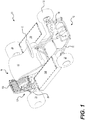
- FIGS 1 and 2 show the general construction of a vehicle 10, generally referred to as a kart 10. Some implementations of the kart 10 may be referred to as a go-kart. It should be understood that the kart 10 could have a construction other than the one described below.
- the kart 10 has a chassis 20 composed at least in part of a tubular structure, also known as a frame 20.
- the frame 20 is made from a plurality of hollow cylindrical steel members and steel brackets that are welded to each other. It is contemplated that at least some of the hollow cylindrical members could be replaced by other types of members such as solid cylindrical members, hollow tubes having a cross-section other than circular, and beams, for example. It is also contemplated that the members and brackets could be made of another type of metal, such as aluminum for example. It is also contemplated that at least some of the members and brackets could be made of a non-metallic material, such as composite materials or plastics for example.
- the members and brackets could be joined to each other by means other than welding, such as by fastening and bonding for example. It is also contemplated that two or more of the members and brackets described above could be cast or otherwise formed as a single component. It is also contemplated that the frame 20 could have more or less members and brackets than illustrated in Figures 1 and 2 , depending on the type of materials used, the required strength and rigidity of the frame 20 and the weight of the components attached to the frame 20 for example.
- a pair of front wheels 22 are rotatably connected to the frame 20.
- a steering wheel 30 is operatively connected to the front wheels 22 for steering the vehicle 10.
- a driver's seat 40 is connected to the frame 20 rearward of the steering wheel 30.
- the drive assembly 100 Disposed in a rear portion 14 of the frame 20, rearward of the driver seat 40, is a drive assembly 100 for driving the kart 10.
- the drive assembly 100 includes an electric motor 105 (see Figure 9 ).
- a rear-wheel drive shaft 86 extends through and is supported by the drive assembly 100.
- a pair of rear wheels 24 are connected to and driven by the rear-wheel drive shaft 86.
- the electric motor 105 is operatively connected to the rear-wheel drive shaft 86 to drive the rear wheels 24.
- the kart 10 could include a twin-engine drive system (with two drive assemblies 100 behind and to either side of the driver's seat 40). In such an implementation, two rear-wheel drive shafts 86 would be installed on both sides of the kart 10, in the two drive assemblies 100.
- Two battery packs 199 supply electric power to the electric motor 105.
- One battery pack 199 is connected to the frame 20 on each of the left and right of the driver's seat 40.
- Each battery 199 is electrically connected to a power inverter 190 by a battery management system (BMS) module (not shown).
- BMS battery management system
- Each BMS module is integrated in its corresponding battery 199. It is contemplated that the BMS modules could be separate from the battery 199.
- the power inverter 190 converts the direct current (DC) from the batteries 199 to alternating current (AC) and supplies the AC to the electric motor 105.
- DC direct current
- AC alternating current
- a brake 89 is disposed around the rear-wheel drive shaft 86 for braking the vehicle 10 (see Figure 2 ).
- the brake 89 is operatively connected to and activated by the brake pedal 46. It is contemplated that the vehicle 10 could have more than one brake 89.
- the drive assembly 100 includes an assembly housing 110 surrounding or partially surrounding components of the drive assembly 100.
- the electric motor 105 included in the drive assembly 100 is disposed within the housing 110.
- the electric motor 105 is an AC motor. More specifically, the electric motor 105 is a permanent magnet synchronous motor (PMSM). It is contemplated that other types of electric motors could be used.
- the housing 110 includes cooling fins 112 to aid in cooling the electric motor 105. It is contemplated that the housing 110 could include more or less cooling fins 112. It is also contemplated that the cooling fins 112 could be larger or smaller than those illustrated for the present implementation.
- the drive assembly 100 includes the power inverter 190 that is operatively connected to the motor 105. As illustrated in Figures 1 to 3 , the power inverter 190 is disposed outside the housing 110, and electrically connects to the motor 105 therethrough. It is contemplated that the housing 110 could additionally surround all or portions of the power inverter 190, depending on the implementation.
- the drive assembly 100 includes two connecting portions 102 extending downward from the housing 110 for securing the drive assembly 100 to the frame 20 of the kart 10.
- Each connecting portion 102 includes several recesses 104 for receiving portions of the frame 20.
- the kart 10 includes two other corresponding connecting portions (not shown) which bolt to the connecting portions 102 from an underside of the frame portion, in order to surround the frame portions and hold the drive assembly in place.
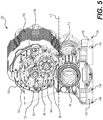
- an output shaft 130 also referred to as a drive shaft 130, extends partially through and out from the electric motor 105. Torque imparted by the motor 105 on the output shaft 130 is transmitted to the rear-wheel drive shaft 86 through a two-stage spur-type reduction gearing 125 (see Fig. 5 ).
- the two-stage gearing 125 is generally vertically arranged, although details on the exact vertical and horizontal positions of the gears of the gearing 125 will vary by implementation.
- An intermediate shaft 140 for supporting the two intermediate gears connecting the motor 105 to the rear-wheel drive shaft 86 in the two-stage gearing 125 is also included within the assembly housing 110.
- the intermediate shaft 140 is disposed below and forward of the output shaft 130. It is contemplated that the intermediate shaft 140 could be disposed directly below or below and rearward of the output shaft 130, depending on the implementation.
- the first stage of the gearing 125 includes a driving gear 132 and a reduction gear 142.
- the driving gear 132 is removably disposed on the output shaft 130.
- the output shaft 130 and the driving gear 132 have complementary splines to ensure that the shaft and gear 130, 132 rotate together, while also allowing the gear 132 to be slid off the shaft 130 when desired.
- Axial movement of the driving gear 132 along the output shaft 130 is prevented by a retaining ring 133 on a motor side of the gear 132, and a ball bearing 152 on an outward side (see Fig. 9 ). Both the output shaft 130 and the driving gear 132 are enclosed by the assembly housing 110.
- the reduction gear 142 is removably disposed on the intermediate shaft 140.
- the intermediate shaft 140 and the reduction gear 142 have complementary splines to ensure that the shaft and gear 140, 142 rotate together, while also allowing the gear 142 to be slid off the shaft 140 when desired.
- On a motor side of the reduction gear 142 axial movement of the reduction gear 142 along the intermediate shaft 140 is impeded by a retaining ring 155 axially fixed to the intermediate shaft 140.
- a ball bearing 156 on an outward side prevents axial movement outward of the reduction gear 142.
- Both the intermediate shaft 140 and the reduction gear 142 are disposed within the assembly housing 110.
- the second stage of the gearing 125 includes a transfer gear 144 and a drive shaft gear 88.
- the transfer gear 144 is disposed on the intermediate shaft 140, leftward from the reduction gear 142 (see Figure 8 ).
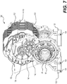
- the drive shaft gear 88 is disposed on the rear-wheel drive shaft 86, as can best be seen in Figure 7 , where a right side housing portion 114 of the assembly housing 100 has been removed. It should be noted that the portion 114 is removed to access components surrounding the rear-wheel drive shaft 86 and the drive shaft gear 88, but need not be removed to access the removable gears 132, 142.
- the transfer gear 144 drives the rear-wheel drive shaft 86 via the drive shaft gear 88.
- the transmission ratio can be changed be removing the gears 132, 142 and reconnecting replacement gears. It should be noted that only the first stage of the two-stage gearing 125 need be changed in order to change the transmission ratio. As such, there is no need to change the drive shaft gear 88, avoiding the need for removing one of the rear wheels 24 or other intervening elements of the kart 10 when modifying the transmission ratio.
- a lubricating oil bath (also called transmission oil) for the rear-wheel drive shaft 86 is included within the housing 110 to provide lubrication to components inside the housing 110, including the rear-wheel drive shaft 86.
- the assembly housing 110 is designed as a closed unit so as to prevent the egress of lubricating oil and the ingress of dirt.
- the lubricating oil settles within the housing 110 and has a maximum resting oil level 118 (see Figs. 3 and 5 ).
- portions of the lubrication oil may be jostled and splashed up into the assembly housing 110, above the maximum level 118.
- an aperture 115 is defined by the assembly housing 110 on the right side of the drive assembly 100.
- the drive assembly 100 further includes a removable panel 150 for selectively covering the aperture 115.
- the panel 150 creates a seal around the aperture 115 when fully connected to the housing 110, preventing transmission oil from getting out and contaminants from getting in through the aperture 115.
- the panel 150 is shown connected to the housing 110 and covering the aperture 115 in Figures 3 and 4 .
- the aperture can best be seen in Figure 5 , where the panel 150 has been removed. It is contemplated that the drive assembly 100 could be disposed in a mirror-image arrangement from the present implementation, the aperture 115 and the panel 150 being disposed on the left side.
- the two-stage gearing 125 is disposed in a generally vertical arrangement.
- the removable gears 132, 142 are disposed generally above the rear-wheel drive shaft 86, and above the maximum resting oil level 118.
- the aperture 115 to access the removable gears 132, 142, as well as the panel 150 covering it, are disposed above the maximum level 118 of the oil.
- the transmission ratio (also called the reduction ratio) of the drive assembly 100 can be changed while the kart 10 is in a normal operating orientation (i.e. with all four wheels 22, 24 still connected to the kart 10 and on level ground) and without generally having to take additional precautions to prevent transmission oil from spilling out of the drive assembly 100.
- One implementation of a method 200 for changing the transmission/reduction ratio will be described in more detail further below.
- the removable panel 150 includes the ball bearing 152 in a bearing housing 154 on its interior side for receiving a right end of the output shaft 130.
- the panel 150 also includes a ball bearing 156 in a bearing housing 158 on its interior side for receiving a right end of the intermediate shaft 140.
- the shafts 130, 140 are press fit into the panel 150 when the panel 150 is pushed into place over the aperture 115. It is contemplated that the panel 150 could include different mechanisms for rotatably holding the ends of the shafts 130, 140.
- the panel 150 includes two alignment pegs 162 for aligning the panel 150 with the aperture 115. It is contemplated that the panel 150 could include more or less alignment pegs 162.
- the panel 150 is connected to the housing 110 by six bolts 164. It is contemplated the panel 150 could connect to the housing 110 by more or less bolts 164. It is also contemplated that the panel 150 could be removably connected to the housing 110 using different means, including for example, different fasteners or hinges allowing the panel 150 to be pivoted open.
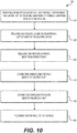
- a method 200 of changing the transmission ratio for the kart 10 will now be described with reference to Figure 10 .
- the method 200 should be performed when the motor 105 is not operating. It is contemplated that the method 200 could include further steps, including but not limited to steps to increase ease and/or safety of the method 200.
- the method 200 generally begins at step 210 with removing the panel 150 from the housing 110 to expose the aperture 115, as well as the gears 132, 142. This is achieved by removing the bolts 164.
- the aperture 115 and the panel 150 are disposed above the maximum resting level 118 of the transmission oil contained within the assembly housing 110 (when the motor 105 is not operating).
- the panel 150 is removable from the housing 110 without having to lift or tilt the kart 10 to prevent spilling of the lubricating oil from within the assembly housing 110. Because the panel 150 does not encircle the rear-wheel drive shaft 86, the panel is removable from the assembly housing 110 without removal of the rear wheel 24 of the kart 10, nor the shaft 86.
- the panel 150 is also removable from the assembly housing 110 without removal of the shafts 130, 140 because the shafts 130, 140 do not extend through the panel 150, and the shaft ends are simply press fitted into the ball bearings 152, 156 on the interior of the panel 150.
- the method 200 continues at step 220 with releasing and removing the driving gear 132 from the output shaft 130 of the electric motor 105.
- the method 200 continues with releasing and removing the reduction gear 142 from the intermediate shaft 140.
- the gears 132, 142 are removed from their respective shafts 130, 140 by sliding the gears 132, 142 off the shafts 130, 140, as the ball bearings 152, 154 no longer prevent axial movement of the gears 132, 142. It is contemplated that a different mechanism from connecting and releasing the gears 132, 142 to/from their respective shafts 130, 140 could be implemented.
- step 240 a replacement driving gear 135 is connected to the output shaft 130.
- step 250 the method 200 continues with connecting a replacement reduction gear 145 to the intermediate shaft 140.
- the replacement gears 135, 145 are illustrated in Figure 11 , where the replacement driving gear 135 has more teeth than the previous driving gear 132 and the replacement reduction gear 145 has less teeth than the previous reduction gear 142.
- the drive assembly 100 with a transmission gearing 126 with the replacement gears 135, 145 will have a higher top speed (but less torque) than the drive assembly 100 with the transmission gearing 125.
- a gear ratio of the driving gear 132 to the reduction gear 142 needs to be different from a gear ratio of the replacement driving gear 135 to the replacement reduction gear 145.
- the replacement driving gear 135 could be the reduction gear 142 and the replacement reduction gear 145 could be the driving gear 132 (depending on the ratio of the gears 132, 142).
- the reduction gear 142 is connected on the output shaft 130 and the driving gear 132 is connected on the intermediate shaft 140.
- steps 220, 230, 240, and 250 could be performed in a different order. It is contemplated, for example, the steps 220 and 230 could be performed in the reverse order. It is also contemplated that the step 220 and then the step 240 could be performed before either of the steps 230 and 250. Similarly, it is contemplated that the step 230 and then the step 250 could be performed before either of the steps 220 and 240.
- the method 200 generally terminates with the panel 150 being reconnected to the assembly housing 110 at step 260 as described above.
Landscapes
- Engineering & Computer Science (AREA)
- General Engineering & Computer Science (AREA)
- Mechanical Engineering (AREA)
- Chemical & Material Sciences (AREA)
- Combustion & Propulsion (AREA)
- Transportation (AREA)
- General Details Of Gearings (AREA)
Applications Claiming Priority (1)
| Application Number | Priority Date | Filing Date | Title |
|---|---|---|---|
| US201762452422P | 2017-01-31 | 2017-01-31 |
Publications (2)
| Publication Number | Publication Date |
|---|---|
| EP3354937A1 true EP3354937A1 (fr) | 2018-08-01 |
| EP3354937B1 EP3354937B1 (fr) | 2022-03-09 |
Family
ID=61094296
Family Applications (1)
| Application Number | Title | Priority Date | Filing Date |
|---|---|---|---|
| EP18154095.6A Active EP3354937B1 (fr) | 2017-01-31 | 2018-01-30 | Kart et ensemble d'entraînement pour kart |
Country Status (2)
| Country | Link |
|---|---|
| US (2) | US10703198B2 (fr) |
| EP (1) | EP3354937B1 (fr) |
Cited By (1)
| Publication number | Priority date | Publication date | Assignee | Title |
|---|---|---|---|---|
| EP4362288A1 (fr) * | 2022-10-28 | 2024-05-01 | BRP-Rotax GmbH & Co. KG | Système de refroidissement d'unité d'entraînement de véhicule électrique |
Families Citing this family (8)
| Publication number | Priority date | Publication date | Assignee | Title |
|---|---|---|---|---|
| US10710635B2 (en) * | 2017-12-18 | 2020-07-14 | Honda Motor Co., Ltd. | Autonomous all-terrain vehicle frame structure |
| US10309517B1 (en) * | 2018-02-20 | 2019-06-04 | Ford Global Technologies, Llc | Transmission pump drive assembly |
| USD865004S1 (en) * | 2018-07-30 | 2019-10-29 | Harley-Davidson Motor Company Group, LLC | Traction motor case |
| USD895486S1 (en) | 2018-07-30 | 2020-09-08 | Harley-Davidson Motor Company Group, LLC | Motorcycle |
| USD903530S1 (en) * | 2019-04-15 | 2020-12-01 | Monolith Inc. | Racing kart |
| US11898630B2 (en) * | 2019-11-14 | 2024-02-13 | Aisin Corporation | Vehicle drive apparatus |
| EP4049871B1 (fr) * | 2019-12-26 | 2024-08-14 | Aisin Corporation | Appareil de commande de véhicule |
| EP4292846A1 (fr) * | 2021-02-09 | 2023-12-20 | Honda Motor Co., Ltd. | Véhicule roulant |
Citations (5)
| Publication number | Priority date | Publication date | Assignee | Title |
|---|---|---|---|---|
| FR2302000A7 (fr) | 1975-02-24 | 1976-09-17 | Hetschel Wilhelm | Voiture automobile de sport, du genre dit kart |
| US4283968A (en) * | 1979-06-25 | 1981-08-18 | Eaton Corporation | Housing assembly for electric vehicle transaxle |
| US7000727B2 (en) | 2000-05-19 | 2006-02-21 | Brp-Rotax Gmbh & Co. Kg | Direct drive assembly and go-kart containing same |
| DE102011084031A1 (de) * | 2011-10-05 | 2013-04-11 | Schaeffler Technologies AG & Co. KG | Elektromotorische Getriebevorrichtung mit Ölsumpfbereich |
| US20140033862A1 (en) * | 2012-08-06 | 2014-02-06 | Chris Tryens | Motor Housing With Integrated Gears |
Family Cites Families (13)
| Publication number | Priority date | Publication date | Assignee | Title |
|---|---|---|---|---|
| US3533484A (en) | 1968-05-16 | 1970-10-13 | Garfield A Wood Jr | Electric power unit |
| US4042055A (en) * | 1975-12-18 | 1977-08-16 | Ward Eugene T | Battery powered vehicle and drive system |
| US5685384A (en) * | 1995-02-03 | 1997-11-11 | Kobilan; Errol D. | Driving system providing a racing experience |
| US6170596B1 (en) * | 1998-10-23 | 2001-01-09 | Challenge Karts U.S.A., Inc. | Racing go-cart vehicle |
| US6717281B1 (en) * | 2000-10-26 | 2004-04-06 | Dennis Brandon | Electric generator and motor drive system |
| US20130025950A1 (en) | 2011-01-26 | 2013-01-31 | Dennis Brandon | Electric cart |
| US9182031B2 (en) * | 2012-12-28 | 2015-11-10 | Kawasaki Jukogyo Kabushiki Kaisha | V-belt type continuously variable transmission |
| ES2453017B1 (es) | 2013-11-17 | 2014-11-07 | Jordi Gasol Angusto | Un kart |
| US9605745B1 (en) * | 2014-02-24 | 2017-03-28 | Andre Kevin Burns | Removable protective cover for motorcyle and all-terrain vehicle engines |
| GB201421435D0 (en) * | 2014-12-02 | 2015-01-14 | Scott Warren | Motorised karts |
| EP3325845B1 (fr) * | 2015-07-20 | 2021-08-04 | National Machine Group | Actionneur électromécanique entraîné par un moteur |
| WO2017114423A1 (fr) * | 2015-12-31 | 2017-07-06 | Byd Company Limited | Ensemble d'essieu moteur électrique et véhicule ayant l'ensemble d'essieu moteur électrique |
| JP6477627B2 (ja) * | 2016-08-12 | 2019-03-06 | トヨタ自動車株式会社 | ハイブリッド車両の潤滑装置 |
-
2018
- 2018-01-29 US US15/881,912 patent/US10703198B2/en active Active
- 2018-01-30 EP EP18154095.6A patent/EP3354937B1/fr active Active
-
2020
- 2020-07-06 US US16/921,376 patent/US20210155092A1/en not_active Abandoned
Patent Citations (5)
| Publication number | Priority date | Publication date | Assignee | Title |
|---|---|---|---|---|
| FR2302000A7 (fr) | 1975-02-24 | 1976-09-17 | Hetschel Wilhelm | Voiture automobile de sport, du genre dit kart |
| US4283968A (en) * | 1979-06-25 | 1981-08-18 | Eaton Corporation | Housing assembly for electric vehicle transaxle |
| US7000727B2 (en) | 2000-05-19 | 2006-02-21 | Brp-Rotax Gmbh & Co. Kg | Direct drive assembly and go-kart containing same |
| DE102011084031A1 (de) * | 2011-10-05 | 2013-04-11 | Schaeffler Technologies AG & Co. KG | Elektromotorische Getriebevorrichtung mit Ölsumpfbereich |
| US20140033862A1 (en) * | 2012-08-06 | 2014-02-06 | Chris Tryens | Motor Housing With Integrated Gears |
Cited By (1)
| Publication number | Priority date | Publication date | Assignee | Title |
|---|---|---|---|---|
| EP4362288A1 (fr) * | 2022-10-28 | 2024-05-01 | BRP-Rotax GmbH & Co. KG | Système de refroidissement d'unité d'entraînement de véhicule électrique |
Also Published As
| Publication number | Publication date |
|---|---|
| EP3354937B1 (fr) | 2022-03-09 |
| US20210155092A1 (en) | 2021-05-27 |
| US20180215255A1 (en) | 2018-08-02 |
| US10703198B2 (en) | 2020-07-07 |
Similar Documents
| Publication | Publication Date | Title |
|---|---|---|
| EP3354937B1 (fr) | Kart et ensemble d'entraînement pour kart | |
| EP2799321B1 (fr) | Véhicule électrique du type à selle | |
| CN111936333B (zh) | 用于框架轨道车辆的车桥组件 | |
| KR101562700B1 (ko) | 전동 삼륜 차량 | |
| US8096910B2 (en) | Travel assembly for dump truck | |
| JP5241652B2 (ja) | ダンプトラックの走行装置 | |
| US8544579B2 (en) | Axle assembly for electric drive machine | |
| US20130065724A1 (en) | Travel drive device for dump truck | |
| EP1690725A2 (fr) | Entraînement électrique de roue à double réduction | |
| US8960362B2 (en) | Lubrication arrangement for a drive axle of a haul vehicle | |
| CN108136891B (zh) | 轮内电动机驱动装置 | |
| US8714656B2 (en) | Travel drive device for dump truck | |
| US8366578B2 (en) | Apparatus and method for lubricating a gear | |
| US8128524B2 (en) | Sheath assembly for a planetary gear | |
| US20160031310A1 (en) | Drivetrain for a ground vehicle | |
| JP2007002919A (ja) | ダンプトラックの走行駆動装置 | |
| WO2025089324A1 (fr) | Véhicule de travail | |
| WO2025089323A1 (fr) | Véhicule de travail | |
| EP4296543A1 (fr) | Ensemble essieu doté d'un déflecteur de lubrifiant | |
| US12589644B2 (en) | Drive axle system having an electric motor | |
| EP4034407B1 (fr) | Agencement de roue de véhicule | |
| JP2000136868A (ja) | トランスファケースの構造 | |
| JP6757630B2 (ja) | インホイールモータ駆動装置 | |
| US20250237295A1 (en) | Transmission arrangement and drive train with such a transmission arrangement |
Legal Events
| Date | Code | Title | Description |
|---|---|---|---|
| PUAI | Public reference made under article 153(3) epc to a published international application that has entered the european phase |
Free format text: ORIGINAL CODE: 0009012 |
|
| STAA | Information on the status of an ep patent application or granted ep patent |
Free format text: STATUS: THE APPLICATION HAS BEEN PUBLISHED |
|
| AK | Designated contracting states |
Kind code of ref document: A1 Designated state(s): AL AT BE BG CH CY CZ DE DK EE ES FI FR GB GR HR HU IE IS IT LI LT LU LV MC MK MT NL NO PL PT RO RS SE SI SK SM TR |
|
| AX | Request for extension of the european patent |
Extension state: BA ME |
|
| STAA | Information on the status of an ep patent application or granted ep patent |
Free format text: STATUS: REQUEST FOR EXAMINATION WAS MADE |
|
| 17P | Request for examination filed |
Effective date: 20190131 |
|
| RBV | Designated contracting states (corrected) |
Designated state(s): AL AT BE BG CH CY CZ DE DK EE ES FI FR GB GR HR HU IE IS IT LI LT LU LV MC MK MT NL NO PL PT RO RS SE SI SK SM TR |
|
| GRAP | Despatch of communication of intention to grant a patent |
Free format text: ORIGINAL CODE: EPIDOSNIGR1 |
|
| STAA | Information on the status of an ep patent application or granted ep patent |
Free format text: STATUS: GRANT OF PATENT IS INTENDED |
|
| INTG | Intention to grant announced |
Effective date: 20200605 |
|
| GRAJ | Information related to disapproval of communication of intention to grant by the applicant or resumption of examination proceedings by the epo deleted |
Free format text: ORIGINAL CODE: EPIDOSDIGR1 |
|
| STAA | Information on the status of an ep patent application or granted ep patent |
Free format text: STATUS: REQUEST FOR EXAMINATION WAS MADE |
|
| INTC | Intention to grant announced (deleted) | ||
| GRAS | Grant fee paid |
Free format text: ORIGINAL CODE: EPIDOSNIGR3 |
|
| STAA | Information on the status of an ep patent application or granted ep patent |
Free format text: STATUS: GRANT OF PATENT IS INTENDED |
|
| GRAP | Despatch of communication of intention to grant a patent |
Free format text: ORIGINAL CODE: EPIDOSNIGR1 |
|
| GRAJ | Information related to disapproval of communication of intention to grant by the applicant or resumption of examination proceedings by the epo deleted |
Free format text: ORIGINAL CODE: EPIDOSDIGR1 |
|
| GRAL | Information related to payment of fee for publishing/printing deleted |
Free format text: ORIGINAL CODE: EPIDOSDIGR3 |
|
| GRAS | Grant fee paid |
Free format text: ORIGINAL CODE: EPIDOSNIGR3 |
|
| GRAP | Despatch of communication of intention to grant a patent |
Free format text: ORIGINAL CODE: EPIDOSNIGR1 |
|
| GRAJ | Information related to disapproval of communication of intention to grant by the applicant or resumption of examination proceedings by the epo deleted |
Free format text: ORIGINAL CODE: EPIDOSDIGR1 |
|
| STAA | Information on the status of an ep patent application or granted ep patent |
Free format text: STATUS: REQUEST FOR EXAMINATION WAS MADE |
|
| INTG | Intention to grant announced |
Effective date: 20210312 |
|
| INTG | Intention to grant announced |
Effective date: 20210325 |
|
| GRAS | Grant fee paid |
Free format text: ORIGINAL CODE: EPIDOSNIGR3 |
|
| STAA | Information on the status of an ep patent application or granted ep patent |
Free format text: STATUS: GRANT OF PATENT IS INTENDED |
|
| INTC | Intention to grant announced (deleted) | ||
| GRAP | Despatch of communication of intention to grant a patent |
Free format text: ORIGINAL CODE: EPIDOSNIGR1 |
|
| INTG | Intention to grant announced |
Effective date: 20210512 |
|
| GRAJ | Information related to disapproval of communication of intention to grant by the applicant or resumption of examination proceedings by the epo deleted |
Free format text: ORIGINAL CODE: EPIDOSDIGR1 |
|
| GRAL | Information related to payment of fee for publishing/printing deleted |
Free format text: ORIGINAL CODE: EPIDOSDIGR3 |
|
| STAA | Information on the status of an ep patent application or granted ep patent |
Free format text: STATUS: REQUEST FOR EXAMINATION WAS MADE |
|
| INTC | Intention to grant announced (deleted) | ||
| GRAP | Despatch of communication of intention to grant a patent |
Free format text: ORIGINAL CODE: EPIDOSNIGR1 |
|
| STAA | Information on the status of an ep patent application or granted ep patent |
Free format text: STATUS: GRANT OF PATENT IS INTENDED |
|
| INTG | Intention to grant announced |
Effective date: 20211028 |
|
| RIN1 | Information on inventor provided before grant (corrected) |
Inventor name: STOPPONI, EMILIO Inventor name: TIRONZELLI, GIULIANO Inventor name: GRUBER, STEFAN Inventor name: KUSEL, HEINZ Inventor name: KRONSTEINER, DOMINIK |
|
| GRAA | (expected) grant |
Free format text: ORIGINAL CODE: 0009210 |
|
| STAA | Information on the status of an ep patent application or granted ep patent |
Free format text: STATUS: THE PATENT HAS BEEN GRANTED |
|
| AK | Designated contracting states |
Kind code of ref document: B1 Designated state(s): AL AT BE BG CH CY CZ DE DK EE ES FI FR GB GR HR HU IE IS IT LI LT LU LV MC MK MT NL NO PL PT RO RS SE SI SK SM TR |
|
| REG | Reference to a national code |
Ref country code: CH Ref legal event code: EP Ref country code: AT Ref legal event code: REF Ref document number: 1474409 Country of ref document: AT Kind code of ref document: T Effective date: 20220315 |
|
| REG | Reference to a national code |
Ref country code: DE Ref legal event code: R096 Ref document number: 602018031836 Country of ref document: DE |
|
| REG | Reference to a national code |
Ref country code: IE Ref legal event code: FG4D |
|
| REG | Reference to a national code |
Ref country code: LT Ref legal event code: MG9D |
|
| REG | Reference to a national code |
Ref country code: NL Ref legal event code: MP Effective date: 20220309 |
|
| PG25 | Lapsed in a contracting state [announced via postgrant information from national office to epo] |
Ref country code: SE Free format text: LAPSE BECAUSE OF FAILURE TO SUBMIT A TRANSLATION OF THE DESCRIPTION OR TO PAY THE FEE WITHIN THE PRESCRIBED TIME-LIMIT Effective date: 20220309 Ref country code: RS Free format text: LAPSE BECAUSE OF FAILURE TO SUBMIT A TRANSLATION OF THE DESCRIPTION OR TO PAY THE FEE WITHIN THE PRESCRIBED TIME-LIMIT Effective date: 20220309 Ref country code: NO Free format text: LAPSE BECAUSE OF FAILURE TO SUBMIT A TRANSLATION OF THE DESCRIPTION OR TO PAY THE FEE WITHIN THE PRESCRIBED TIME-LIMIT Effective date: 20220609 Ref country code: LT Free format text: LAPSE BECAUSE OF FAILURE TO SUBMIT A TRANSLATION OF THE DESCRIPTION OR TO PAY THE FEE WITHIN THE PRESCRIBED TIME-LIMIT Effective date: 20220309 Ref country code: HR Free format text: LAPSE BECAUSE OF FAILURE TO SUBMIT A TRANSLATION OF THE DESCRIPTION OR TO PAY THE FEE WITHIN THE PRESCRIBED TIME-LIMIT Effective date: 20220309 Ref country code: BG Free format text: LAPSE BECAUSE OF FAILURE TO SUBMIT A TRANSLATION OF THE DESCRIPTION OR TO PAY THE FEE WITHIN THE PRESCRIBED TIME-LIMIT Effective date: 20220609 |
|
| PG25 | Lapsed in a contracting state [announced via postgrant information from national office to epo] |
Ref country code: LV Free format text: LAPSE BECAUSE OF FAILURE TO SUBMIT A TRANSLATION OF THE DESCRIPTION OR TO PAY THE FEE WITHIN THE PRESCRIBED TIME-LIMIT Effective date: 20220309 Ref country code: GR Free format text: LAPSE BECAUSE OF FAILURE TO SUBMIT A TRANSLATION OF THE DESCRIPTION OR TO PAY THE FEE WITHIN THE PRESCRIBED TIME-LIMIT Effective date: 20220610 Ref country code: FI Free format text: LAPSE BECAUSE OF FAILURE TO SUBMIT A TRANSLATION OF THE DESCRIPTION OR TO PAY THE FEE WITHIN THE PRESCRIBED TIME-LIMIT Effective date: 20220309 |
|
| PG25 | Lapsed in a contracting state [announced via postgrant information from national office to epo] |
Ref country code: NL Free format text: LAPSE BECAUSE OF FAILURE TO SUBMIT A TRANSLATION OF THE DESCRIPTION OR TO PAY THE FEE WITHIN THE PRESCRIBED TIME-LIMIT Effective date: 20220309 |
|
| PG25 | Lapsed in a contracting state [announced via postgrant information from national office to epo] |
Ref country code: SM Free format text: LAPSE BECAUSE OF FAILURE TO SUBMIT A TRANSLATION OF THE DESCRIPTION OR TO PAY THE FEE WITHIN THE PRESCRIBED TIME-LIMIT Effective date: 20220309 Ref country code: SK Free format text: LAPSE BECAUSE OF FAILURE TO SUBMIT A TRANSLATION OF THE DESCRIPTION OR TO PAY THE FEE WITHIN THE PRESCRIBED TIME-LIMIT Effective date: 20220309 Ref country code: RO Free format text: LAPSE BECAUSE OF FAILURE TO SUBMIT A TRANSLATION OF THE DESCRIPTION OR TO PAY THE FEE WITHIN THE PRESCRIBED TIME-LIMIT Effective date: 20220309 Ref country code: PT Free format text: LAPSE BECAUSE OF FAILURE TO SUBMIT A TRANSLATION OF THE DESCRIPTION OR TO PAY THE FEE WITHIN THE PRESCRIBED TIME-LIMIT Effective date: 20220711 Ref country code: ES Free format text: LAPSE BECAUSE OF FAILURE TO SUBMIT A TRANSLATION OF THE DESCRIPTION OR TO PAY THE FEE WITHIN THE PRESCRIBED TIME-LIMIT Effective date: 20220309 Ref country code: EE Free format text: LAPSE BECAUSE OF FAILURE TO SUBMIT A TRANSLATION OF THE DESCRIPTION OR TO PAY THE FEE WITHIN THE PRESCRIBED TIME-LIMIT Effective date: 20220309 Ref country code: CZ Free format text: LAPSE BECAUSE OF FAILURE TO SUBMIT A TRANSLATION OF THE DESCRIPTION OR TO PAY THE FEE WITHIN THE PRESCRIBED TIME-LIMIT Effective date: 20220309 |
|
| PG25 | Lapsed in a contracting state [announced via postgrant information from national office to epo] |
Ref country code: PL Free format text: LAPSE BECAUSE OF FAILURE TO SUBMIT A TRANSLATION OF THE DESCRIPTION OR TO PAY THE FEE WITHIN THE PRESCRIBED TIME-LIMIT Effective date: 20220309 Ref country code: IS Free format text: LAPSE BECAUSE OF FAILURE TO SUBMIT A TRANSLATION OF THE DESCRIPTION OR TO PAY THE FEE WITHIN THE PRESCRIBED TIME-LIMIT Effective date: 20220709 Ref country code: AL Free format text: LAPSE BECAUSE OF FAILURE TO SUBMIT A TRANSLATION OF THE DESCRIPTION OR TO PAY THE FEE WITHIN THE PRESCRIBED TIME-LIMIT Effective date: 20220309 |
|
| REG | Reference to a national code |
Ref country code: DE Ref legal event code: R097 Ref document number: 602018031836 Country of ref document: DE |
|
| PLBE | No opposition filed within time limit |
Free format text: ORIGINAL CODE: 0009261 |
|
| STAA | Information on the status of an ep patent application or granted ep patent |
Free format text: STATUS: NO OPPOSITION FILED WITHIN TIME LIMIT |
|
| PG25 | Lapsed in a contracting state [announced via postgrant information from national office to epo] |
Ref country code: DK Free format text: LAPSE BECAUSE OF FAILURE TO SUBMIT A TRANSLATION OF THE DESCRIPTION OR TO PAY THE FEE WITHIN THE PRESCRIBED TIME-LIMIT Effective date: 20220309 |
|
| 26N | No opposition filed |
Effective date: 20221212 |
|
| PG25 | Lapsed in a contracting state [announced via postgrant information from national office to epo] |
Ref country code: SI Free format text: LAPSE BECAUSE OF FAILURE TO SUBMIT A TRANSLATION OF THE DESCRIPTION OR TO PAY THE FEE WITHIN THE PRESCRIBED TIME-LIMIT Effective date: 20220309 |
|
| REG | Reference to a national code |
Ref country code: AT Ref legal event code: UEP Ref document number: 1474409 Country of ref document: AT Kind code of ref document: T Effective date: 20220309 |
|
| REG | Reference to a national code |
Ref country code: CH Ref legal event code: PL |
|
| GBPC | Gb: european patent ceased through non-payment of renewal fee |
Effective date: 20230130 |
|
| PG25 | Lapsed in a contracting state [announced via postgrant information from national office to epo] |
Ref country code: LU Free format text: LAPSE BECAUSE OF NON-PAYMENT OF DUE FEES Effective date: 20230130 |
|
| REG | Reference to a national code |
Ref country code: BE Ref legal event code: MM Effective date: 20230131 |
|
| PG25 | Lapsed in a contracting state [announced via postgrant information from national office to epo] |
Ref country code: LI Free format text: LAPSE BECAUSE OF NON-PAYMENT OF DUE FEES Effective date: 20230131 Ref country code: GB Free format text: LAPSE BECAUSE OF NON-PAYMENT OF DUE FEES Effective date: 20230130 Ref country code: CH Free format text: LAPSE BECAUSE OF NON-PAYMENT OF DUE FEES Effective date: 20230131 |
|
| PG25 | Lapsed in a contracting state [announced via postgrant information from national office to epo] |
Ref country code: BE Free format text: LAPSE BECAUSE OF NON-PAYMENT OF DUE FEES Effective date: 20230131 |
|
| PG25 | Lapsed in a contracting state [announced via postgrant information from national office to epo] |
Ref country code: IE Free format text: LAPSE BECAUSE OF NON-PAYMENT OF DUE FEES Effective date: 20230130 |
|
| PG25 | Lapsed in a contracting state [announced via postgrant information from national office to epo] |
Ref country code: MC Free format text: LAPSE BECAUSE OF FAILURE TO SUBMIT A TRANSLATION OF THE DESCRIPTION OR TO PAY THE FEE WITHIN THE PRESCRIBED TIME-LIMIT Effective date: 20220309 |
|
| PG25 | Lapsed in a contracting state [announced via postgrant information from national office to epo] |
Ref country code: MC Free format text: LAPSE BECAUSE OF FAILURE TO SUBMIT A TRANSLATION OF THE DESCRIPTION OR TO PAY THE FEE WITHIN THE PRESCRIBED TIME-LIMIT Effective date: 20220309 |
|
| PG25 | Lapsed in a contracting state [announced via postgrant information from national office to epo] |
Ref country code: CY Free format text: LAPSE BECAUSE OF FAILURE TO SUBMIT A TRANSLATION OF THE DESCRIPTION OR TO PAY THE FEE WITHIN THE PRESCRIBED TIME-LIMIT; INVALID AB INITIO Effective date: 20180130 |
|
| PG25 | Lapsed in a contracting state [announced via postgrant information from national office to epo] |
Ref country code: HU Free format text: LAPSE BECAUSE OF FAILURE TO SUBMIT A TRANSLATION OF THE DESCRIPTION OR TO PAY THE FEE WITHIN THE PRESCRIBED TIME-LIMIT; INVALID AB INITIO Effective date: 20180130 |
|
| PG25 | Lapsed in a contracting state [announced via postgrant information from national office to epo] |
Ref country code: TR Free format text: LAPSE BECAUSE OF FAILURE TO SUBMIT A TRANSLATION OF THE DESCRIPTION OR TO PAY THE FEE WITHIN THE PRESCRIBED TIME-LIMIT Effective date: 20220309 |
|
| PGFP | Annual fee paid to national office [announced via postgrant information from national office to epo] |
Ref country code: DE Payment date: 20260127 Year of fee payment: 9 |
|
| PGFP | Annual fee paid to national office [announced via postgrant information from national office to epo] |
Ref country code: AT Payment date: 20260119 Year of fee payment: 9 |
|
| PGFP | Annual fee paid to national office [announced via postgrant information from national office to epo] |
Ref country code: IT Payment date: 20260123 Year of fee payment: 9 |
|
| PGFP | Annual fee paid to national office [announced via postgrant information from national office to epo] |
Ref country code: FR Payment date: 20260126 Year of fee payment: 9 |