EP3354939B1 - Planetengetriebesystem und gasturbinenmotor mit einem planetengetriebesystem - Google Patents
Planetengetriebesystem und gasturbinenmotor mit einem planetengetriebesystem Download PDFInfo
- Publication number
- EP3354939B1 EP3354939B1 EP17153747.5A EP17153747A EP3354939B1 EP 3354939 B1 EP3354939 B1 EP 3354939B1 EP 17153747 A EP17153747 A EP 17153747A EP 3354939 B1 EP3354939 B1 EP 3354939B1
- Authority
- EP
- European Patent Office
- Prior art keywords
- planetary gear
- gear system
- extension elements
- pins
- base structure
- Prior art date
- Legal status (The legal status is an assumption and is not a legal conclusion. Google has not performed a legal analysis and makes no representation as to the accuracy of the status listed.)
- Active
Links
Images



Classifications
-
- F—MECHANICAL ENGINEERING; LIGHTING; HEATING; WEAPONS; BLASTING
- F16—ENGINEERING ELEMENTS AND UNITS; GENERAL MEASURES FOR PRODUCING AND MAINTAINING EFFECTIVE FUNCTIONING OF MACHINES OR INSTALLATIONS; THERMAL INSULATION IN GENERAL
- F16H—GEARING
- F16H57/00—General details of gearing
- F16H57/08—General details of gearing of gearings with members having orbital motion
- F16H57/082—Planet carriers
-
- F—MECHANICAL ENGINEERING; LIGHTING; HEATING; WEAPONS; BLASTING
- F02—COMBUSTION ENGINES; HOT-GAS OR COMBUSTION-PRODUCT ENGINE PLANTS
- F02C—GAS-TURBINE PLANTS; AIR INTAKES FOR JET-PROPULSION PLANTS; CONTROLLING FUEL SUPPLY IN AIR-BREATHING JET-PROPULSION PLANTS
- F02C7/00—Features, components parts, details or accessories, not provided for in, or of interest apart form groups F02C1/00 - F02C6/00; Air intakes for jet-propulsion plants
- F02C7/36—Power transmission arrangements between the different shafts of the gas turbine plant, or between the gas-turbine plant and the power user
-
- F—MECHANICAL ENGINEERING; LIGHTING; HEATING; WEAPONS; BLASTING
- F05—INDEXING SCHEMES RELATING TO ENGINES OR PUMPS IN VARIOUS SUBCLASSES OF CLASSES F01-F04
- F05D—INDEXING SCHEME FOR ASPECTS RELATING TO NON-POSITIVE-DISPLACEMENT MACHINES OR ENGINES, GAS-TURBINES OR JET-PROPULSION PLANTS
- F05D2260/00—Function
- F05D2260/40—Transmission of power
- F05D2260/403—Transmission of power through the shape of the drive components
- F05D2260/4031—Transmission of power through the shape of the drive components as in toothed gearing
- F05D2260/40311—Transmission of power through the shape of the drive components as in toothed gearing of the epicyclical, planetary or differential type
-
- Y—GENERAL TAGGING OF NEW TECHNOLOGICAL DEVELOPMENTS; GENERAL TAGGING OF CROSS-SECTIONAL TECHNOLOGIES SPANNING OVER SEVERAL SECTIONS OF THE IPC; TECHNICAL SUBJECTS COVERED BY FORMER USPC CROSS-REFERENCE ART COLLECTIONS [XRACs] AND DIGESTS
- Y02—TECHNOLOGIES OR APPLICATIONS FOR MITIGATION OR ADAPTATION AGAINST CLIMATE CHANGE
- Y02T—CLIMATE CHANGE MITIGATION TECHNOLOGIES RELATED TO TRANSPORTATION
- Y02T50/00—Aeronautics or air transport
- Y02T50/60—Efficient propulsion technologies, e.g. for aircraft
Definitions
- the invention relates to a planetary gear system with the features of claim 1 and a gas turbine engine with a planetary gear system with the features of claim 12.
- Planetary gear systems are e.g. used in geared turbofan engines for aircrafts.
- the purpose of the planetary gear system in this exemplary application is the reduction of the rotational speed from a driving turbine to a propulsive fan stage. In this and other applications considerable mechanical loads are acting on the planetary gear system resulting in displacements of the planetary gears.
- One such system with two parallel rows of planetary gears is known from US 2016 / 0177841 A1 .
- the planet carrier supports a plurality of short pinions and long pinions and includes a first supporting wall supporting one ends of the short pinions and the long pinions, second support walls supporting the other ends of the short pinions, third supporting walls supporting the other ends of the long pinions, first connecting walls connecting the first supporting wall and the second supporting walls, pairs of second connecting walls facing each other, arranged on both sides of each long pinion in the rotational direction of the carrier, and connecting the second supporting walls and the third supporting walls, and the third connecting walls connecting each pair of second connecting walls to each other on at least one of the radial inner side and the radial outer side of each long pinion.
- the engine comprises a plurality of planetary gears coupled to a carrier device.
- the planetary gear system has front planetary gears mounted on pins in a front row and aft planetary gears mounted on pins in an aft row, the two rows being parallel to each other in the axial direction of the planetary gear system.
- the carrier device comprises a ring-like base structure around a rotational axis of the carrier device, which generally is the rotational axis of the gas turbine engine.
- the pins for the planetary gears are coupled to the carrier device through first and second extension elements for the positioning of the pins relative to the base structure.
- the second extension elements axially extending the respective pins further away from the base structure than the pins positioned by the first extension elements, so that the aft planetary gears are positioned in the aft row axially further away from the base structure than the front planetary gears in the front row.
- the first extension elements, in particular arms as part of the first extension elements form first inclination angles ⁇ A which are smaller than second inclination angles ⁇ B formed by the second extension elements, in particular arms as parts of the second extension elements, wherein the inclination angles are measured between the plane of the base structure and a projection of the extension elements through the centers of the pins in radial directions.
- the different inclination angles allow an efficient positioning of the pins in the two parallel rows.
- the base structure comprises extension elements radially extending inwards from the base structure.
- extension elements are part of a support structure with a wave-like shape, the axial low points of the support structure relative to the base structure position the pins in the front row and the axial high points of the support structure relative to the base structure position the pins in the aft row.
- the wave-like shape is an efficient way to create pin positions in two parallel planes.
- extension elements and hence the pins can be positioned symmetrically around the rotational axis of the planetary gear system.
- the pins are separated by an equal angle, in particular by 45°.
- the extension elements can in some embodiments comprise linear arms and / or arc-shape arms extending radially inwards from the base structure. Using arms instead of solid blocks allows a lighter design of the support structure.
- the first extension elements can have section moduli W A which are lower than the section moduli W B of the second extension elements.
- the ratio W B /W A can be in the range from 4 to 12, more particular in the range from 6 to 10, and more particular 8. This means that the parts of the support structure which are designed to be further away from the base structure have a stiffer design to account for higher mechanical loads.
- planetary gear system can comprise between three and six front planetary gears and between three and six aft planetary gears.
- extension elements and / or the support structure are formed in one piece with the base structure.
- the support structure has a band-like shape and the base structure has a flat, ring-like shape, the thickness of the support structure having in particular the same magnitude as the thickness of the base structure.
- a gas turbine engine is generally indicated at 10, having a principal and rotational axis 11.
- the engine 10 comprises, in axial flow series, an air intake 12, a propulsive fan 13 (Here with a single stage. Other embodiments might have more than one stage,), a planetary gear system 100 (i.e. a gearbox), an intermediate pressure compressor 15, a high-pressure compressor 16, combustion equipment 17, a high-pressure turbine 18, an intermediate-pressure turbine 19 and an exhaust nozzle 20.
- a fan casing 21 generally surrounds the engine 10 and defines the intake 12.
- the gas turbine engine 10 works in the conventional manner so that air entering the intake 12 is accelerated by the propulsive fan 13 to produce two air flows: a first air flow into the intermediate pressure compressor 15 and a second air flow which passes through a bypass duct 22 to provide propulsive thrust.
- the intermediate pressure compressor 15 compresses the air flow directed into it before delivering that air to the high pressure compressor 16 where further compression takes place.
- the compressed air exhausted from the high-pressure compressor 16 is directed into the combustion equipment 17 where it is mixed with fuel and the mixture combusted.
- the resultant hot combustion products then expand through, and thereby drive the high pressure turbine 18 and intermediate pressure turbine 19 before being exhausted through the nozzle 20 to provide additional propulsive thrust.
- An intermediate pressure shaft also drives the propulsive fan 13 via the planetary gear system 100.
- the planetary gear system 100 is a reduction gearbox in that it gears down the rate of rotation of the propulsive fan 13 by comparison with the intermediate pressure compressor 15 and intermediate pressure turbine 19.
- the planetary gear system100 in this embodiment is an epicyclic planetary gear system having a rotating ring gear 32, rotating and orbiting planet gears 31 supported by a planet carrier driven by a rotating sun gear 30.
- the planet gears 31 (see Fig. 2 , 3 , 4 ) are fixed relative to the sun gear 30.
- the shaft driving the gear system 100 transmits torque to the sun gear 30.
- the centres of the planetary gears 31 are fixed, they rotate around themselves.
- the rotating ring gear 32 provides torque to the output side of the gear system 100.
- Fig. 1 has a specific shaft arrangement which is understood not to be limiting.
- the embodiments described in the following can also work with a 2- or 3-shaft arrangement.
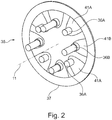
- Fig. 2 shows a perspective view of a first embodiment of a carrier device 35 for planetary gears 31 (not shown here) in a planetary gear system 100 with the rotational axis 11.
- the carrier device 35 comprises a base structure 37 in the form of a flat ring around the rotational axis 11.
- the pins are collinearly oriented in an axial direction.
- the pins 36A, 36B are coupled to a base structure 37 of the carrier device 35 through extension elements 41A, 41B for the positioning of the pins 36A, 36B relative to the base structure 37.
- the extension elements 41A, 41B extend radially inwards from the base structure 37.
- the planetary gears 31 are positioned in two axially parallel rows A, B of four planetary gears 31 each: the front planetary gears 31 in the front row A, the aft planetary gears 31 in the aft row B.
- the second extension elements 41B axially extend the respective pins 36B in this embodiment further away from the base structure 37 than the pins 36A positioned by the first extension elements 41A. Therefore, the aft planetary gears 31 are positioned in the aft row B axially further away from the base structure 37 than the front planetary gears 31 in the front row A.
- the relatively long pins 36B for the aft planetary gears 31 have wider base to position the aft planetary gears 31 in the aft row B.
- the shorter pins 36A position the front gears 31 in the front row A.
- FIG. 3A, 3B, and 3C schematic views of a base design of a carrier device 35 for a planetary gear system 100 are shown, wherein the gear system 100 also comprises two parallel rows A, B of planetary gears 31 (not shown here).
- the views in Fig. 3A, 3B, and 3C are shown to indicate the geometric relationships of the rows A, B for the planetary gears 31.
- Each row A, B comprises four planetary gears 31 in a star formation around the rotational axis 11.
- the planetary gears 31 are mounted on pins 36A, 36B which are coupled to the carrier device 35. All pins 36A, 36B extend in a collinear, axial direction away from a base structure 37 of the carrier device 35. Both rows A, B in this embodiment are axially on the same side the base structure 37.
- the pins 36B of the aft row B extend axially further away from the base structure 37 than the pins 36A of the first row A. Therefore, the two sets of four planetary gears 31 will operate in two separate, parallel rows A, B.
- the forces F can be considerable, i.e. in the order of 100 - 300 kN on each pin, so that an even distribution of the forces F, and hence an even distribution of torque over the two rows A, B is important.
- FIG. 4A, 4B, 4C, and 4D different views of second embodiment of a carrier device 35 for two rows of planetary gears 31 are shown.
- the planetary gears 31 themselves are not shown in these figures for the sake of simplicity.
- Fig. 4A, 4B, 4C, and 4D are mainly intended to show the structural features of the carrier device 35 from different angles as indicated by the coordinate systems shown for each of the figures.
- Fig. 4A shows a top view of the carrier device 35 which corresponds to the view shown in Fig. 3C , i.e. the eight pins 36A, 36B in both parallel rows A, B are visible.
- Fig. 4B shows a bottom view of the carrier device 35, so that the pins 36A, 36B are not visible.
- Fig. 4C shows a side view of the carrier device 35 so that the parallel rows A, B are visible, corresponding to the view shown in Fig. 3A . In this view it is best seen, that the pins 36A, 36B extend axially away in the same direction from the base structure 37.
- Fig. 4D shows a perspective view of the embodiment of the carrier device 35.
- the embodiment comprises the base structure 37 in a form of a flat metal ring coupled with extension elements 41A, 41B for the pins 36A, 36B extending radially inwards and axially outwards.
- the extension element 41A, 41B are part of a support structure 40 with a wave-like shape.
- the low points of the support structure 40 measured axially relative to the base structure 37 position the pins 36A in the front row A.
- the high points of the support structure 40 measured axially relative to the base structure 37 position the pins 36B in the aft row B.
- the support structure 40 comprises eight extension elements 41A, B pointing radially inwards (best seen in Fig. 4A ) and axially away in x-direction (best seen in Fig. 4C ) from the ring-like base structure 37. There is one extension element 41A, 41B for each pin 36A, 36B.
- the extension elements 41A, 41B are part of a wave-shaped support structure 40.
- the extension elements 41A, 41B are formed from wave segments of the support structure 40 having roughly a triangular shape, i.e. the extension elements 41 have two arms 43 linking the apex to the ring-like base structure 37.
- the two arms 43 of the extension element 41A, 41B form in this embodiment an arc extending radially inwards and axially outwards.
- the apex of the arc (with the pins 36A, 36B) and the two connection points of the arms 43 with the base structure 37 form triangles. This is an example in which the extension elements 41A, 41B and the support structure 40 are both manufactured in one piece with the base structure 37.
- the base of the triangles are at the ring-like base structure 37, the apex of the triangle is radially and axially pointing away from the base structure 37.
- the base lines of the extension elements 41A, 41B are symmetrically positioned around the rotational axis 11 of the base structure 37, i.e. the base lines of the triangles are equal. Since the support structure 40 is formed here as a band-like structure formed together with the base structure 37, the extension elements 41A, 41B comprise holes 42 (here each shaped roughly elliptically) which reduces the weight of the carrier device 35.
- the support structure 40 forms a three-dimensional band-like and wave-like structure within the flat, ring-like base structure 37, the eight axial apexes of the wave being the location of the pins 36A, 36B.
- the wave form extends circumferentially around the inner circumference of the base structure 37 as e.g. seen in Fig. 4A and it extends axially away from the base structure 37 as e.g. seen in Fig. 4C or 4D .
- the essentially triangular extension elements 41A, B (abstracted from the wave segments) have sides with different inclination angles ⁇ A , ⁇ B .
- FIG. 5A, 5B, 5C and 5D show identical top views of the embodiment of Fig. 4 , the view in Fig. 5C being rotated by 45° from the view on Fig. 5A.
- Fig. 5B and 5D show respective side views of Fig. 5C and Fig. 5A , the direction of view indicated by an arrow in Fig. 5A and 5C .
- the support structure 40 with the extension elements 41A, 41B is represented as a simplified structure of the embodiment shown in Fig. 4A, 4B, 4C and 4D highlighting the essentially triangular shape of the wave segments, i.e. the extension elements 41A, 41B.
- the different heights h A , h B of the extension elements 41A, 41B above the base structure are due to the different inclination angles ⁇ A , ⁇ B .
- the inclination angles ⁇ A , ⁇ B are measured between the plane of the base structure 37 and a projection of the extension elements 41A, 41B through the centers of the pins 36A, 36B in radial directions on the plane of the drawings Fig 5B and 5D .
- the extension elements 41A of the front row A have smaller inclination angle ⁇ A (see Fig. 5D ) than the inclination angle ⁇ B of the extension elements 41B of the aft row B (see Fig. 5B ).
- pins 36A, 36B can be located in parallel rows A, B.
- all eight pins 36A, 36B are spaced 45° apart.
- the four pins 36A in the front row A, and the four pins 36B in the aft row B are spaced 90° apart. All eight pins 36A, 36B are positioned on a circle within the ring-like base structure 37.
- This band-like and wave-like support structure 40 allows a stiff and light-weight design of the carrier device 35.
- the support structure 40 is not band- or wave-like as described above but comprises extension elements 41A, 41B comprise more linear, sticklike elements.
- FIG. 6A and 6B Such a third embodiment is shown in Fig. 6A and 6B .
- the essentially triangular shape of the extension elements 41A, 41B can be better seen as in the band- and wave-like support structure 37 in the embodiment described above.
- the extension elements 41A, 41B in the third embodiment comprise two linear arms 43 each.
- the inclination angles ⁇ A of the extension elements 41A of the front row A are smaller than the inclination angles ⁇ B of the extension elements 41B of the aft row B.
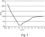
- one aspect of the invention is to minimize the tangential displacement angle ⁇ (see e. g. Fig. 3C of the pins 36A, 36B, in particular the relative tangential displacement between pins 36A, 36B in different the rows A, B.
- the tangential displacement angle ⁇ depends inter alia on the section modulus W A , W B of the support structure 40 for the pins 36A, 36B.
- the section moduli W A for the extension elements 41A for the pins 36A in the front row A are smaller than the section moduli W B for the extension elements 41B of the pins 36B in the aft row B.
- Ratios of W B /W A in the range of 4 to 12, in particular in the range between 6 and 10 can be used.
- the percentwise variation of the tangential displacement is shown in Fig. 7 in dependence of the ratio of the inclination angles ( ⁇ B / ⁇ A ).
Landscapes
- Engineering & Computer Science (AREA)
- General Engineering & Computer Science (AREA)
- Mechanical Engineering (AREA)
- Chemical & Material Sciences (AREA)
- Combustion & Propulsion (AREA)
- Retarders (AREA)
Claims (12)
- Planetengetriebesystem (100) für einen Gasturbinenmotor (10), insbesondere ein Flugzeugstrahltriebwerk, mit mehreren Planetengetrieben (31), die mit einer Trägervorrichtung (35) gekoppelt sind, wobei vordere Planetengetriebe (31) auf Stiften (36A) in einer vorderen Reihe (A) montiert sind und hintere Planetengetriebe (31) auf Stiften (36B) in einer hinteren Reihe (B) montiert sind, wobei die zwei Reihen (A, B) in Axialrichtung des Planetengetriebesystems (100) parallel zueinander sind,
dadurch gekennzeichnet, dass
die Trägervorrichtung (35) eine ringartige Basisstruktur (37) um eine Drehachse (11) der Trägervorrichtung (35) aufweist,
die Stifte (36A, 36B) durch erste Verlängerungselemente (41A) und zweite Verlängerungselemente (41B) zur Positionierung der Stifte (36A, 36B) in Bezug zur Basisstruktur (37) mit der Trägervorrichtung (35) gekoppelt sind,
die zweiten Verlängerungselemente (41B) die jeweiligen Stifte (36B) von der Basisstruktur (37) weiter weg verlängern als die von den ersten Verlängerungselementen (41A) positionierten Stifte (36A), sodass die hinteren Planetengetriebe (31) in der hinteren Reihe (B) axial von der Basisstruktur (37) weiter weg positioniert sind als die vorderen Planetengetriebe (31) in der vorderen Reihe (A), und
die ersten Verlängerungselemente (41A), insbesondere Arme (43), als Teil der ersten Verlängerungselemente (41A) erste Neigungswinkel (αA) ausbilden, die kleiner als zweite Neigungswinkel (αB) sind, die von den zweiten Verlängerungselementen (41B), insbesondere Armen (43), als Teil der zweiten Verlängerungselemente (41B) ausgebildet sind, wobei die Neigungswinkel (αA, αB) zwischen der Ebene der Basisstruktur (37) und einem Vorsprung der Verlängerungselemente (41A, 41B) durch die Mittelpunkte der Stifte (36A, 36B) in Radialrichtung gemessen werden. - Planetengetriebesystem (100) nach Anspruch 1, wobei sich die Verlängerungselemente (41A, 41B) von der Basisstruktur (37) radial nach innen erstrecken.
- Planetengetriebesystem (100) nach Anspruch 1 oder 2, wobei die Verlängerungselemente (41A, 41B) Teil einer wellenförmigen Tragstruktur (40) sind,
die axialen Tiefpunkte der Tragstruktur (40) in Bezug zur Basisstruktur (37) zum Positionieren der Stifte (36A) in der vorderen Reihe (A) und
die axialen Höhepunkte der Tragstruktur (40) in Bezug zur Basisstruktur (37) zum Positionieren der Stifte (36B) in der hinteren Reihe (B). - Planetengetriebesystem (100) nach mindestens einem der vorstehenden Ansprüche, wobei die Verlängerungselemente (41A, 41B) und somit die Stifte (36A, 36B) symmetrisch um die Drehachse (11) des Planetengetriebesystems (100) positioniert sind.
- Planetengetriebesystem (100) nach mindestens einem der vorstehenden Ansprüche, wobei die Stifte (36A, 36B) durch einen gleichen Winkel, insbesondere 45°, getrennt sind.
- Planetengetriebesystem (100) nach mindestens einem der vorstehenden Ansprüche, wobei das Verhältnis der Neigungswinkel αB/αA αB/αA = 1,25 beträgt.
- Planetengetriebesystem (100) nach mindestens einem der vorstehenden Ansprüche, wobei die Verlängerungselemente (41A, 41B) gerade Arme und/oder bogenförmige Arme umfassen, die sich von der Basisstruktur (37) nach innen erstrecken.
- Planetengetriebesystem (100) nach mindestens einem der vorstehenden Ansprüche, wobei die ersten Verlängerungselemente (41A) Schnittmoduln (WA) aufweisen, die kleiner als die Schnittmoduln (WB) der zweiten Verlängerungselemente (41B) sind, insbesondere mit einem Verhältnis WB/WA im Bereich von 4 bis 12, insbesondere im Bereich von 6 bis 10, insbesondere von 8.
- Planetengetriebesystem (100) nach mindestens einem der vorstehenden Ansprüche, zwischen drei und sechs vordere Planetengetriebe und zwischen drei und sechs hintere Planetengetriebe umfassend.
- Planetengetriebesystem (100) nach mindestens einem der vorstehenden Ansprüche, wobei die Verlängerungselemente (41A, 41B) und/oder die Tragstruktur (40) mit der Basisstruktur (37) einstückig ausgebildet sind.
- Planetengetriebesystem (100) nach mindestens einem der vorstehenden Ansprüche, wobei die Tragstruktur (40) bandförmig ist und die Basisstruktur (37) eine flache Ringform aufweist, wobei die Stärke der Tragstruktur (40) insbesondere dieselbe Größe wie die Stärke der Basisstruktur (37) aufweist.
- Gasturbinenmotor (10) mit einem Planetengetriebesystem (100) nach mindestens einem der vorstehenden Ansprüche.
Priority Applications (2)
| Application Number | Priority Date | Filing Date | Title |
|---|---|---|---|
| EP17153747.5A EP3354939B1 (de) | 2017-01-30 | 2017-01-30 | Planetengetriebesystem und gasturbinenmotor mit einem planetengetriebesystem |
| US15/880,301 US10422421B2 (en) | 2017-01-30 | 2018-01-25 | Planetary gear system and gas turbine engine with a planetary gear system |
Applications Claiming Priority (1)
| Application Number | Priority Date | Filing Date | Title |
|---|---|---|---|
| EP17153747.5A EP3354939B1 (de) | 2017-01-30 | 2017-01-30 | Planetengetriebesystem und gasturbinenmotor mit einem planetengetriebesystem |
Publications (2)
| Publication Number | Publication Date |
|---|---|
| EP3354939A1 EP3354939A1 (de) | 2018-08-01 |
| EP3354939B1 true EP3354939B1 (de) | 2020-03-04 |
Family
ID=57944310
Family Applications (1)
| Application Number | Title | Priority Date | Filing Date |
|---|---|---|---|
| EP17153747.5A Active EP3354939B1 (de) | 2017-01-30 | 2017-01-30 | Planetengetriebesystem und gasturbinenmotor mit einem planetengetriebesystem |
Country Status (2)
| Country | Link |
|---|---|
| US (1) | US10422421B2 (de) |
| EP (1) | EP3354939B1 (de) |
Families Citing this family (2)
| Publication number | Priority date | Publication date | Assignee | Title |
|---|---|---|---|---|
| DE102021202882A1 (de) | 2021-03-24 | 2022-09-29 | Zf Friedrichshafen Ag | Planetengetriebe |
| DE102021205296B4 (de) | 2021-05-25 | 2023-02-02 | Zf Friedrichshafen Ag | Planetengetriebe |
Family Cites Families (8)
| Publication number | Priority date | Publication date | Assignee | Title |
|---|---|---|---|---|
| DE19835257C2 (de) | 1998-08-04 | 2002-06-13 | Baumeister & Ostler Gmbh Co | Fensterrollo mit versenkbaren Führungselementen |
| JP4423716B2 (ja) | 1999-10-08 | 2010-03-03 | アイシン・エィ・ダブリュ株式会社 | プラネタリキャリア |
| ATE332457T1 (de) * | 2003-01-27 | 2006-07-15 | Timken Co | Planetengetriebesysteme |
| DE10324362A1 (de) * | 2003-05-27 | 2004-12-16 | A. Friedr. Flender Ag | Getriebe für den Antrieb eines Drehrohres |
| US7654929B2 (en) * | 2007-02-02 | 2010-02-02 | Ford Global Technologies, Llc | Assembly including a planetary pinion carrier and one-way clutch |
| US8517672B2 (en) * | 2010-02-23 | 2013-08-27 | General Electric Company | Epicyclic gearbox |
| JP6119575B2 (ja) * | 2013-11-25 | 2017-04-26 | アイシン・エィ・ダブリュ株式会社 | プラネタリキャリヤ |
| EP3034850B1 (de) | 2014-12-18 | 2019-12-04 | United Technologies Corporation | Planetengetriebesystem für turbomaschinen |
-
2017
- 2017-01-30 EP EP17153747.5A patent/EP3354939B1/de active Active
-
2018
- 2018-01-25 US US15/880,301 patent/US10422421B2/en active Active
Non-Patent Citations (1)
| Title |
|---|
| None * |
Also Published As
| Publication number | Publication date |
|---|---|
| US10422421B2 (en) | 2019-09-24 |
| EP3354939A1 (de) | 2018-08-01 |
| US20180216724A1 (en) | 2018-08-02 |
Similar Documents
| Publication | Publication Date | Title |
|---|---|---|
| EP3372808B1 (de) | Getriebeturbofan | |
| EP2949882B1 (de) | Getriebearchitektur für den bläserantrieb mittels einer kleinvolumigen und mit hochgeschwindigkeit laufender turbine | |
| EP2360391B1 (de) | Epizyklisches Getriebe | |
| EP3587773B1 (de) | Gasturbine | |
| US11022044B1 (en) | Geared gas turbine engine | |
| EP2925982B1 (de) | Gasturbinenmotor mit verzahnter architektur und verbessertem schmier- und fehlausrichtungstolerantem wälzlagersystem | |
| US8905887B2 (en) | Unison ring gear assembly | |
| US11313441B2 (en) | Planetary gearbox and method for assembling a planetary gearbox | |
| US20200157971A1 (en) | Structural assembly for a gas turbine engine | |
| EP3244018B1 (de) | Verzahnter verstellring zur betätigung von mehrstufigen variablen leit-schaufeln | |
| US10260619B2 (en) | Carrier structure for an epicyclic gear drive, epicyclic gear drive and turbo engine with an epicyclic gear drive | |
| US20220260020A1 (en) | Structural assembly for a gas turbine engine | |
| EP3354940B1 (de) | Planetengetriebesystem und gasturbinenmotor mit einem planetengetriebesystem | |
| US10422421B2 (en) | Planetary gear system and gas turbine engine with a planetary gear system | |
| EP3587768A1 (de) | Gasturbine | |
| US11668372B2 (en) | Planet-carrier for an epicyclic gearing | |
| US12297779B2 (en) | Geared gas turbine engine | |
| US11187158B2 (en) | Gearing arrangement and method for manufacturing the gearing arrangement | |
| US11698006B2 (en) | Structural assembly for a gas turbine engine | |
| EP4663978A1 (de) | Verbundzahnrad | |
| Sato et al. | Design, Analysis, and Tests of Differential Planetary Gear System for Open Rotor Power Gearbox | |
| CN112610684A (zh) | 用于周转齿轮系统壳体组件的轴承弹簧 | |
| CN112610338A (zh) | 用于周转齿轮系统外罩组件的静态弯曲接头 |
Legal Events
| Date | Code | Title | Description |
|---|---|---|---|
| PUAI | Public reference made under article 153(3) epc to a published international application that has entered the european phase |
Free format text: ORIGINAL CODE: 0009012 |
|
| STAA | Information on the status of an ep patent application or granted ep patent |
Free format text: STATUS: REQUEST FOR EXAMINATION WAS MADE |
|
| 17P | Request for examination filed |
Effective date: 20180208 |
|
| AK | Designated contracting states |
Kind code of ref document: A1 Designated state(s): AL AT BE BG CH CY CZ DE DK EE ES FI FR GB GR HR HU IE IS IT LI LT LU LV MC MK MT NL NO PL PT RO RS SE SI SK SM TR |
|
| AX | Request for extension of the european patent |
Extension state: BA ME |
|
| STAA | Information on the status of an ep patent application or granted ep patent |
Free format text: STATUS: EXAMINATION IS IN PROGRESS |
|
| 17Q | First examination report despatched |
Effective date: 20180817 |
|
| GRAP | Despatch of communication of intention to grant a patent |
Free format text: ORIGINAL CODE: EPIDOSNIGR1 |
|
| STAA | Information on the status of an ep patent application or granted ep patent |
Free format text: STATUS: GRANT OF PATENT IS INTENDED |
|
| INTG | Intention to grant announced |
Effective date: 20190821 |
|
| RIN1 | Information on inventor provided before grant (corrected) |
Inventor name: SCOGNAMIGLIO, DOMENICO |
|
| GRAS | Grant fee paid |
Free format text: ORIGINAL CODE: EPIDOSNIGR3 |
|
| GRAJ | Information related to disapproval of communication of intention to grant by the applicant or resumption of examination proceedings by the epo deleted |
Free format text: ORIGINAL CODE: EPIDOSDIGR1 |
|
| GRAL | Information related to payment of fee for publishing/printing deleted |
Free format text: ORIGINAL CODE: EPIDOSDIGR3 |
|
| STAA | Information on the status of an ep patent application or granted ep patent |
Free format text: STATUS: EXAMINATION IS IN PROGRESS |
|
| GRAR | Information related to intention to grant a patent recorded |
Free format text: ORIGINAL CODE: EPIDOSNIGR71 |
|
| STAA | Information on the status of an ep patent application or granted ep patent |
Free format text: STATUS: GRANT OF PATENT IS INTENDED |
|
| GRAA | (expected) grant |
Free format text: ORIGINAL CODE: 0009210 |
|
| STAA | Information on the status of an ep patent application or granted ep patent |
Free format text: STATUS: THE PATENT HAS BEEN GRANTED |
|
| INTC | Intention to grant announced (deleted) | ||
| INTG | Intention to grant announced |
Effective date: 20200110 |
|
| AK | Designated contracting states |
Kind code of ref document: B1 Designated state(s): AL AT BE BG CH CY CZ DE DK EE ES FI FR GB GR HR HU IE IS IT LI LT LU LV MC MK MT NL NO PL PT RO RS SE SI SK SM TR |
|
| REG | Reference to a national code |
Ref country code: GB Ref legal event code: FG4D |
|
| REG | Reference to a national code |
Ref country code: CH Ref legal event code: EP |
|
| REG | Reference to a national code |
Ref country code: AT Ref legal event code: REF Ref document number: 1240747 Country of ref document: AT Kind code of ref document: T Effective date: 20200315 |
|
| REG | Reference to a national code |
Ref country code: DE Ref legal event code: R096 Ref document number: 602017012435 Country of ref document: DE |
|
| REG | Reference to a national code |
Ref country code: IE Ref legal event code: FG4D |
|
| PG25 | Lapsed in a contracting state [announced via postgrant information from national office to epo] |
Ref country code: NO Free format text: LAPSE BECAUSE OF FAILURE TO SUBMIT A TRANSLATION OF THE DESCRIPTION OR TO PAY THE FEE WITHIN THE PRESCRIBED TIME-LIMIT Effective date: 20200604 Ref country code: RS Free format text: LAPSE BECAUSE OF FAILURE TO SUBMIT A TRANSLATION OF THE DESCRIPTION OR TO PAY THE FEE WITHIN THE PRESCRIBED TIME-LIMIT Effective date: 20200304 Ref country code: FI Free format text: LAPSE BECAUSE OF FAILURE TO SUBMIT A TRANSLATION OF THE DESCRIPTION OR TO PAY THE FEE WITHIN THE PRESCRIBED TIME-LIMIT Effective date: 20200304 |
|
| REG | Reference to a national code |
Ref country code: NL Ref legal event code: MP Effective date: 20200304 |
|
| PG25 | Lapsed in a contracting state [announced via postgrant information from national office to epo] |
Ref country code: LV Free format text: LAPSE BECAUSE OF FAILURE TO SUBMIT A TRANSLATION OF THE DESCRIPTION OR TO PAY THE FEE WITHIN THE PRESCRIBED TIME-LIMIT Effective date: 20200304 Ref country code: HR Free format text: LAPSE BECAUSE OF FAILURE TO SUBMIT A TRANSLATION OF THE DESCRIPTION OR TO PAY THE FEE WITHIN THE PRESCRIBED TIME-LIMIT Effective date: 20200304 Ref country code: SE Free format text: LAPSE BECAUSE OF FAILURE TO SUBMIT A TRANSLATION OF THE DESCRIPTION OR TO PAY THE FEE WITHIN THE PRESCRIBED TIME-LIMIT Effective date: 20200304 Ref country code: BG Free format text: LAPSE BECAUSE OF FAILURE TO SUBMIT A TRANSLATION OF THE DESCRIPTION OR TO PAY THE FEE WITHIN THE PRESCRIBED TIME-LIMIT Effective date: 20200604 Ref country code: GR Free format text: LAPSE BECAUSE OF FAILURE TO SUBMIT A TRANSLATION OF THE DESCRIPTION OR TO PAY THE FEE WITHIN THE PRESCRIBED TIME-LIMIT Effective date: 20200605 |
|
| REG | Reference to a national code |
Ref country code: LT Ref legal event code: MG4D |
|
| PG25 | Lapsed in a contracting state [announced via postgrant information from national office to epo] |
Ref country code: NL Free format text: LAPSE BECAUSE OF FAILURE TO SUBMIT A TRANSLATION OF THE DESCRIPTION OR TO PAY THE FEE WITHIN THE PRESCRIBED TIME-LIMIT Effective date: 20200304 |
|
| PG25 | Lapsed in a contracting state [announced via postgrant information from national office to epo] |
Ref country code: PT Free format text: LAPSE BECAUSE OF FAILURE TO SUBMIT A TRANSLATION OF THE DESCRIPTION OR TO PAY THE FEE WITHIN THE PRESCRIBED TIME-LIMIT Effective date: 20200729 Ref country code: SK Free format text: LAPSE BECAUSE OF FAILURE TO SUBMIT A TRANSLATION OF THE DESCRIPTION OR TO PAY THE FEE WITHIN THE PRESCRIBED TIME-LIMIT Effective date: 20200304 Ref country code: LT Free format text: LAPSE BECAUSE OF FAILURE TO SUBMIT A TRANSLATION OF THE DESCRIPTION OR TO PAY THE FEE WITHIN THE PRESCRIBED TIME-LIMIT Effective date: 20200304 Ref country code: EE Free format text: LAPSE BECAUSE OF FAILURE TO SUBMIT A TRANSLATION OF THE DESCRIPTION OR TO PAY THE FEE WITHIN THE PRESCRIBED TIME-LIMIT Effective date: 20200304 Ref country code: SM Free format text: LAPSE BECAUSE OF FAILURE TO SUBMIT A TRANSLATION OF THE DESCRIPTION OR TO PAY THE FEE WITHIN THE PRESCRIBED TIME-LIMIT Effective date: 20200304 Ref country code: ES Free format text: LAPSE BECAUSE OF FAILURE TO SUBMIT A TRANSLATION OF THE DESCRIPTION OR TO PAY THE FEE WITHIN THE PRESCRIBED TIME-LIMIT Effective date: 20200304 Ref country code: RO Free format text: LAPSE BECAUSE OF FAILURE TO SUBMIT A TRANSLATION OF THE DESCRIPTION OR TO PAY THE FEE WITHIN THE PRESCRIBED TIME-LIMIT Effective date: 20200304 Ref country code: IS Free format text: LAPSE BECAUSE OF FAILURE TO SUBMIT A TRANSLATION OF THE DESCRIPTION OR TO PAY THE FEE WITHIN THE PRESCRIBED TIME-LIMIT Effective date: 20200704 Ref country code: CZ Free format text: LAPSE BECAUSE OF FAILURE TO SUBMIT A TRANSLATION OF THE DESCRIPTION OR TO PAY THE FEE WITHIN THE PRESCRIBED TIME-LIMIT Effective date: 20200304 |
|
| REG | Reference to a national code |
Ref country code: AT Ref legal event code: MK05 Ref document number: 1240747 Country of ref document: AT Kind code of ref document: T Effective date: 20200304 |
|
| REG | Reference to a national code |
Ref country code: DE Ref legal event code: R097 Ref document number: 602017012435 Country of ref document: DE |
|
| PLBE | No opposition filed within time limit |
Free format text: ORIGINAL CODE: 0009261 |
|
| STAA | Information on the status of an ep patent application or granted ep patent |
Free format text: STATUS: NO OPPOSITION FILED WITHIN TIME LIMIT |
|
| PG25 | Lapsed in a contracting state [announced via postgrant information from national office to epo] |
Ref country code: AT Free format text: LAPSE BECAUSE OF FAILURE TO SUBMIT A TRANSLATION OF THE DESCRIPTION OR TO PAY THE FEE WITHIN THE PRESCRIBED TIME-LIMIT Effective date: 20200304 Ref country code: DK Free format text: LAPSE BECAUSE OF FAILURE TO SUBMIT A TRANSLATION OF THE DESCRIPTION OR TO PAY THE FEE WITHIN THE PRESCRIBED TIME-LIMIT Effective date: 20200304 Ref country code: IT Free format text: LAPSE BECAUSE OF FAILURE TO SUBMIT A TRANSLATION OF THE DESCRIPTION OR TO PAY THE FEE WITHIN THE PRESCRIBED TIME-LIMIT Effective date: 20200304 |
|
| 26N | No opposition filed |
Effective date: 20201207 |
|
| PG25 | Lapsed in a contracting state [announced via postgrant information from national office to epo] |
Ref country code: SI Free format text: LAPSE BECAUSE OF FAILURE TO SUBMIT A TRANSLATION OF THE DESCRIPTION OR TO PAY THE FEE WITHIN THE PRESCRIBED TIME-LIMIT Effective date: 20200304 Ref country code: PL Free format text: LAPSE BECAUSE OF FAILURE TO SUBMIT A TRANSLATION OF THE DESCRIPTION OR TO PAY THE FEE WITHIN THE PRESCRIBED TIME-LIMIT Effective date: 20200304 |
|
| PGFP | Annual fee paid to national office [announced via postgrant information from national office to epo] |
Ref country code: GB Payment date: 20210128 Year of fee payment: 5 |
|
| PG25 | Lapsed in a contracting state [announced via postgrant information from national office to epo] |
Ref country code: MC Free format text: LAPSE BECAUSE OF FAILURE TO SUBMIT A TRANSLATION OF THE DESCRIPTION OR TO PAY THE FEE WITHIN THE PRESCRIBED TIME-LIMIT Effective date: 20200304 |
|
| REG | Reference to a national code |
Ref country code: CH Ref legal event code: PL |
|
| PG25 | Lapsed in a contracting state [announced via postgrant information from national office to epo] |
Ref country code: LU Free format text: LAPSE BECAUSE OF NON-PAYMENT OF DUE FEES Effective date: 20210130 |
|
| REG | Reference to a national code |
Ref country code: BE Ref legal event code: MM Effective date: 20210131 |
|
| PG25 | Lapsed in a contracting state [announced via postgrant information from national office to epo] |
Ref country code: CH Free format text: LAPSE BECAUSE OF NON-PAYMENT OF DUE FEES Effective date: 20210131 Ref country code: LI Free format text: LAPSE BECAUSE OF NON-PAYMENT OF DUE FEES Effective date: 20210131 |
|
| PG25 | Lapsed in a contracting state [announced via postgrant information from national office to epo] |
Ref country code: IE Free format text: LAPSE BECAUSE OF NON-PAYMENT OF DUE FEES Effective date: 20210130 |
|
| PG25 | Lapsed in a contracting state [announced via postgrant information from national office to epo] |
Ref country code: BE Free format text: LAPSE BECAUSE OF NON-PAYMENT OF DUE FEES Effective date: 20210131 |
|
| GBPC | Gb: european patent ceased through non-payment of renewal fee |
Effective date: 20220130 |
|
| PG25 | Lapsed in a contracting state [announced via postgrant information from national office to epo] |
Ref country code: GB Free format text: LAPSE BECAUSE OF NON-PAYMENT OF DUE FEES Effective date: 20220130 |
|
| PG25 | Lapsed in a contracting state [announced via postgrant information from national office to epo] |
Ref country code: CY Free format text: LAPSE BECAUSE OF FAILURE TO SUBMIT A TRANSLATION OF THE DESCRIPTION OR TO PAY THE FEE WITHIN THE PRESCRIBED TIME-LIMIT Effective date: 20200304 |
|
| P01 | Opt-out of the competence of the unified patent court (upc) registered |
Effective date: 20230528 |
|
| PG25 | Lapsed in a contracting state [announced via postgrant information from national office to epo] |
Ref country code: HU Free format text: LAPSE BECAUSE OF FAILURE TO SUBMIT A TRANSLATION OF THE DESCRIPTION OR TO PAY THE FEE WITHIN THE PRESCRIBED TIME-LIMIT; INVALID AB INITIO Effective date: 20170130 |
|
| PG25 | Lapsed in a contracting state [announced via postgrant information from national office to epo] |
Ref country code: MK Free format text: LAPSE BECAUSE OF FAILURE TO SUBMIT A TRANSLATION OF THE DESCRIPTION OR TO PAY THE FEE WITHIN THE PRESCRIBED TIME-LIMIT Effective date: 20200304 |
|
| PG25 | Lapsed in a contracting state [announced via postgrant information from national office to epo] |
Ref country code: MT Free format text: LAPSE BECAUSE OF FAILURE TO SUBMIT A TRANSLATION OF THE DESCRIPTION OR TO PAY THE FEE WITHIN THE PRESCRIBED TIME-LIMIT Effective date: 20200304 |
|
| PG25 | Lapsed in a contracting state [announced via postgrant information from national office to epo] |
Ref country code: TR Free format text: LAPSE BECAUSE OF FAILURE TO SUBMIT A TRANSLATION OF THE DESCRIPTION OR TO PAY THE FEE WITHIN THE PRESCRIBED TIME-LIMIT Effective date: 20200304 |
|
| PGFP | Annual fee paid to national office [announced via postgrant information from national office to epo] |
Ref country code: DE Payment date: 20260127 Year of fee payment: 10 |
|
| PGFP | Annual fee paid to national office [announced via postgrant information from national office to epo] |
Ref country code: FR Payment date: 20260126 Year of fee payment: 10 |