EP3354945A1 - Zweiteilige ringverschlussanordnung mit konstanter geschwindigkeit - Google Patents
Zweiteilige ringverschlussanordnung mit konstanter geschwindigkeit Download PDFInfo
- Publication number
- EP3354945A1 EP3354945A1 EP18151059.5A EP18151059A EP3354945A1 EP 3354945 A1 EP3354945 A1 EP 3354945A1 EP 18151059 A EP18151059 A EP 18151059A EP 3354945 A1 EP3354945 A1 EP 3354945A1
- Authority
- EP
- European Patent Office
- Prior art keywords
- carbon ring
- face
- seal assembly
- axially
- disposed
- Prior art date
- Legal status (The legal status is an assumption and is not a legal conclusion. Google has not performed a legal analysis and makes no representation as to the accuracy of the status listed.)
- Granted
Links
Images



Classifications
-
- F—MECHANICAL ENGINEERING; LIGHTING; HEATING; WEAPONS; BLASTING
- F01—MACHINES OR ENGINES IN GENERAL; ENGINE PLANTS IN GENERAL; STEAM ENGINES
- F01D—NON-POSITIVE DISPLACEMENT MACHINES OR ENGINES, e.g. STEAM TURBINES
- F01D11/00—Preventing or minimising internal leakage of working-fluid, e.g. between stages
- F01D11/003—Preventing or minimising internal leakage of working-fluid, e.g. between stages by packing rings; Mechanical seals
-
- F—MECHANICAL ENGINEERING; LIGHTING; HEATING; WEAPONS; BLASTING
- F16—ENGINEERING ELEMENTS AND UNITS; GENERAL MEASURES FOR PRODUCING AND MAINTAINING EFFECTIVE FUNCTIONING OF MACHINES OR INSTALLATIONS; THERMAL INSULATION IN GENERAL
- F16J—PISTONS; CYLINDERS; SEALINGS
- F16J15/00—Sealings
- F16J15/16—Sealings between relatively-moving surfaces
-
- F—MECHANICAL ENGINEERING; LIGHTING; HEATING; WEAPONS; BLASTING
- F16—ENGINEERING ELEMENTS AND UNITS; GENERAL MEASURES FOR PRODUCING AND MAINTAINING EFFECTIVE FUNCTIONING OF MACHINES OR INSTALLATIONS; THERMAL INSULATION IN GENERAL
- F16J—PISTONS; CYLINDERS; SEALINGS
- F16J15/00—Sealings
- F16J15/16—Sealings between relatively-moving surfaces
- F16J15/26—Sealings between relatively-moving surfaces with stuffing-boxes for rigid sealing rings
- F16J15/30—Sealings between relatively-moving surfaces with stuffing-boxes for rigid sealing rings with sealing rings made of carbon
-
- F—MECHANICAL ENGINEERING; LIGHTING; HEATING; WEAPONS; BLASTING
- F16—ENGINEERING ELEMENTS AND UNITS; GENERAL MEASURES FOR PRODUCING AND MAINTAINING EFFECTIVE FUNCTIONING OF MACHINES OR INSTALLATIONS; THERMAL INSULATION IN GENERAL
- F16J—PISTONS; CYLINDERS; SEALINGS
- F16J15/00—Sealings
- F16J15/44—Free-space packings
- F16J15/441—Free-space packings with floating ring
-
- F—MECHANICAL ENGINEERING; LIGHTING; HEATING; WEAPONS; BLASTING
- F05—INDEXING SCHEMES RELATING TO ENGINES OR PUMPS IN VARIOUS SUBCLASSES OF CLASSES F01-F04
- F05D—INDEXING SCHEME FOR ASPECTS RELATING TO NON-POSITIVE-DISPLACEMENT MACHINES OR ENGINES, GAS-TURBINES OR JET-PROPULSION PLANTS
- F05D2220/00—Application
- F05D2220/30—Application in turbines
- F05D2220/32—Application in turbines in gas turbines
-
- F—MECHANICAL ENGINEERING; LIGHTING; HEATING; WEAPONS; BLASTING
- F05—INDEXING SCHEMES RELATING TO ENGINES OR PUMPS IN VARIOUS SUBCLASSES OF CLASSES F01-F04
- F05D—INDEXING SCHEME FOR ASPECTS RELATING TO NON-POSITIVE-DISPLACEMENT MACHINES OR ENGINES, GAS-TURBINES OR JET-PROPULSION PLANTS
- F05D2240/00—Components
- F05D2240/60—Shafts
-
- F—MECHANICAL ENGINEERING; LIGHTING; HEATING; WEAPONS; BLASTING
- F05—INDEXING SCHEMES RELATING TO ENGINES OR PUMPS IN VARIOUS SUBCLASSES OF CLASSES F01-F04
- F05D—INDEXING SCHEME FOR ASPECTS RELATING TO NON-POSITIVE-DISPLACEMENT MACHINES OR ENGINES, GAS-TURBINES OR JET-PROPULSION PLANTS
- F05D2250/00—Geometry
- F05D2250/10—Two-dimensional
- F05D2250/18—Two-dimensional patterned
- F05D2250/182—Two-dimensional patterned crenellated, notched
-
- F—MECHANICAL ENGINEERING; LIGHTING; HEATING; WEAPONS; BLASTING
- F05—INDEXING SCHEMES RELATING TO ENGINES OR PUMPS IN VARIOUS SUBCLASSES OF CLASSES F01-F04
- F05D—INDEXING SCHEME FOR ASPECTS RELATING TO NON-POSITIVE-DISPLACEMENT MACHINES OR ENGINES, GAS-TURBINES OR JET-PROPULSION PLANTS
- F05D2260/00—Function
- F05D2260/50—Kinematic linkage, i.e. transmission of position
- F05D2260/52—Kinematic linkage, i.e. transmission of position involving springs
Definitions
- the present disclosure relates to gas turbine engines, and more specifically to seals for use in turbine sections of gas turbine engines.
- Carbon seal assemblies are used in gas turbine engines between rotating shafts and static frames, and between two rotating shafts. Carbon seal assemblies maintain lubricating fluids within a bearing compartment or bearing chamber and seal against hot air intrusion or cooling air leakage. Some carbon seal assemblies include multiple carbon rings stacked axially against one another. During engine operation, these carbon rings can rotate against one another and against adjacent seats, causing the carbon rings to wear unevenly and prematurely.
- a carbon ring for a seal assembly in a gas turbine engine includes an outer face extending circumferentially around a center axis of the carbon ring.
- the carbon ring also includes an inner face extending around the center axis and disposed radially inward from the outer face.
- a forward face of the carbon ring extends radially between the inner face and the outer face.
- a rear face of the carbon ring extends radially between the inner face and the outer face and is disposed axially opposite the forward face.
- At least one tab extends axially from at least one of the forward face and the rear face.
- a seal assembly for a gas turbine engine in another embodiment, includes an annular front seat positioned on a center axis of the seal assembly and an annular rear seat disposed axially aft of the annular front seat.
- a first carbon ring is positioned axially between the annular front seat and the annular rear seat.
- a second carbon ring is positioned axially between the first carbon ring and the annular rear seat. The first carbon ring rotationally interlocks with the second carbon ring.
- a seal assembly for a gas turbine engine in another embodiment, includes an annular front seat positioned on a center axis of the seal assembly and an annular rear seat disposed axially aft of the annular front seat.
- a first carbon ring is positioned axially between the annular front seat and the annular rear seat.
- a second carbon ring is positioned axially
- the first carbon ring rotationally interlocks with the second carbon ring.
- the disclosure relates to a seal assembly for use in a gas turbine engine between two rotating shafts or between a rotating shaft and a static structure.
- the seal assembly includes two carbon rings stacked together along a center axis between a front seat and a rear seat.
- the two carbon rings can rotate about the center axis and can rotate relative the front seat, the rear seat, and any surrounding structure.
- the two carbon rings interlock with each other such that the two carbon rings do not rotate relative to one another.
- a spring can be disposed between the two carbon rings to bias one ring against the front seat and to bias the second ring against the rear seat. Because the two carbon rings interlock with each other, the two carbon rings wear more evenly and do not wear out the spring.
- the two rings can be symmetrical to each other so that two copies of a single part can be used for the two rings, thereby reducing manufacturing complexity and cost of the seal assembly.
- FIG. 1 is a quarter-sectional view that schematically illustrates example gas turbine engine 20 that includes fan section 22, compressor section 24, combustor section 26 and turbine section 28.
- Fan section 22 drives air along bypass flow path B while compressor section 24 draws air in along core flow path C where air is compressed and communicated to combustor section 26.
- combustor section 26 air is mixed with fuel and ignited to generate a high pressure exhaust gas stream that expands through turbine section 28 where energy is extracted and utilized to drive fan section 22 and compressor section 24.
- turbofan gas turbine engine depicts a turbofan gas turbine engine
- concepts described herein are not limited to use with turbofans as the teachings may be applied to other types of turbine engines; for example, an industrial gas turbine; a reverse-flow gas turbine engine; and a turbine engine including a three-spool architecture in which three spools concentrically rotate about a common axis and where a low spool enables a low pressure turbine to drive a fan via a gearbox, an intermediate spool that enables an intermediate pressure turbine to drive a first compressor of the compressor section, and a high spool that enables a high pressure turbine to drive a high pressure compressor of the compressor section.
- the example gas turbine engine 20 generally includes low speed spool 30 and high speed spool 32 mounted for rotation about center axis CA of gas turbine engine 20 relative to engine static structure 36 via several bearing assemblies 38. It should be understood that various bearing assemblies 38 at various locations may alternatively or additionally be provided.
- Low speed spool 30 generally includes inner shaft 40 that connects fan 42 and low pressure (or first) compressor section 44 to low pressure (or first) turbine section 46.
- Inner shaft 40 drives fan 42 through a speed change device, such as geared architecture 48, to drive fan 42 at a lower speed than low speed spool 30.
- High-speed spool 32 includes outer shaft 50 that interconnects high pressure (or second) compressor section 52 and high pressure (or second) turbine section 54.
- Inner shaft 40 and outer shaft 50 are concentric and rotate via bearing assemblies 38 about center axis CA.
- Combustor 56 is arranged between high pressure compressor 52 and high pressure turbine 54.
- Mid-turbine frame 58 of engine static structure 36 can be arranged generally between high pressure turbine 54 and low pressure turbine 46.
- Mid-turbine frame 58 further supports bearing assemblies 38 in turbine section 28 as well as setting airflow entering the low pressure turbine 46.
- Mid-turbine frame 58 includes vanes 60, which are in the core airflow path and function as an inlet guide vane for low pressure turbine 46.
- the core airflow C is compressed first by low pressure compressor 44 and then by high pressure compressor 52 mixed with fuel and ignited in combustor 56 to produce high speed exhaust gases that are then expanded through high pressure turbine 54, mid-turbine frame 58, and low pressure turbine 46.
- gas turbine engine 20 includes seal assembly 62 to reduce or eliminate air and fluid leakage between static structure 36 and outer shaft 50.
- FIG. 2 is a cross-sectional view of static structure 36, outer shaft 50, and seal assembly 62 of gas turbine engine 20 shown in FIG. 1 .
- seal assembly 62 includes seal static liner 64, first carbon ring 66, second carbon ring 68, front seat 70, rear seat 72, and springs 74 (only one of which is shown in FIG. 2 ).
- Front seat 70 includes radial segment 76, axial segment 78, outer surface 80, and inner surface 82.
- Rear seat 72 includes radial segment 84, axial segment 86, outer surface 88, and inner surface 90.
- First carbon ring 66 includes first forward face 92, first rear face 94, first outer face 96, and first inner face 98.
- Second carbon ring 68 includes second forward face 104, second rear face 106, second outer face 108, and second inner face 110.
- Spring cavity 111 is formed between first carbon ring 66 and second carbon ring 68.
- Seal assembly 62 is disposed radially between static structure 36 and outer shaft 50 relative to center axis CA.
- Seal static liner 64 is connected to static structure 36 such that seal static liner 64 does not rotate about center axis CA.
- Seal static liner 64 extends circumferentially around first carbon ring 66 and second carbon ring 68.
- First carbon ring 66, second carbon ring 68, front seat 70, and rear seat 72 are positioned radially between seal static liner 64 and outer shaft 50.
- Front seat 70 is annular and connected to outer shaft 50 such that front seat 70 rotates with outer shaft 50 during operation of gas turbine engine 20.
- Radial segment 76 of front seat 70 extends radially from outer surface 80 of front seat 70 to inner surface 82 of front seat 70.
- Axial segment 78 of front seat 70 extends axially aftward from radial segment 76 of front seat 70 and is positioned radially between outer surface 80 and inner surface 82 of front seat 70.
- Rear seat 72 is also annular and connected to outer shaft 50 such that rear seat 72 rotates with outer shaft 50 during operation of gas turbine engine 20.
- Radial segment 84 of rear seat 72 is positioned axially aft of radial segment 76 of front seat 70 and extends radially from inner surface 90 of rear seat 72 to outer surface 88 of rear seat 72.
- Axial segment 86 of rear seat 72 extends axially forward from radial segment 84 of rear seat 72.
- axial segment 78 of front seat 70 can overlap axial segment 86 of rear seat 72 such that axial segment 86 is disposed radially inward of axial segment 78.
- axial segment 86 of rear seat 72 spaces radial segment 76 of front seat 70 from radial segment 84 of rear seat 72 so as to accommodate first carbon ring 66 and second carbon ring 68 between radial segment 76 and radial segment 84.
- First carbon ring 66 is disposed axially between radial segment 76 of front seat 70 and radial segment 84 of rear seat 72.
- First carbon ring 66 extends radially between first outer face 96 and first inner face 98, and extends axially between first forward face 92 and first rear face 94.
- First outer face 96 of first carbon ring 66 is in contact with seal static liner 64 and first forward face 92 of first carbon ring 66 is in contact with radial segment 76 of front seat 70.
- Second carbon ring 68 is disposed axially between first carbon ring 66 and radial segment 84 of rear seat 72. Second carbon ring 68 extends radially between second outer face 108 and second inner face 110, and extends axially between second forward face 104 and second rear face 106. Second forward face 104 of second carbon ring 68 faces first rear face 94 of first carbon ring 66. Second outer face 108 of second carbon ring 68 contacts seal static liner 64. Second rear face 106 of second carbon ring 68 contacts radial segment 84 of rear seat 72.
- Spring cavity 111 is formed between first carbon ring 66 and second carbon ring 68. As shown in FIG. 2 , spring cavity 111 extends axially forward into first carbon ring 66 and axially through first rear face 94 of first carbon ring 66. Spring cavity 111 also extends axially aftward into second carbon ring 68 and axially through second forward face 104 of second carbon ring 68. Spring cavity 111 can extend fully around an inner circumference of first carbon ring 66 and second carbon ring 68. Springs 74 are disposed inside spring cavity 111 to bias first carbon ring 66 forward and against front seat 70, and to bias second carbon ring 68 aftward against rear seat 72.
- Springs 74 extend axially between first carbon ring 66 and second carbon ring 68 and can be wave springs, coil springs, or any other kind of springs that are capable of fitting within spring cavity 111 and surviving the thermal environment of seal assembly 62 while exerting the necessary load between first carbon ring 66 and second carbon ring 68.
- Springs 74 can also include combinations of the above-described springs.
- springs 74 can include wave springs and coil springs in the same assembly.
- Each of springs 74 can be disposed between a pair of flat washers (not shown) inside spring cavity 111. The flat washers reduce wear between springs 74 and first carbon ring 66 and second carbon ring 68.
- first carbon ring 66 and second carbon ring 68 are in contact with seal static liner 64 and are free to rotate relative seal static liner 64 so as to reduce stress and wear on first carbon ring 66 and second carbon ring 68.
- First carbon ring 66 and second carbon ring 68 are also free to rotate relative to front seat 70 and rear seat 72 to reduce stress on first carbon ring 66 and second carbon ring 68.
- first carbon ring 66 interlocks with second carbon ring 68 such that first carbon ring 66 and second carbon ring 68 rotate together about center axis CA and not independent of one another.
- FIG. 3A is a perspective view of first carbon ring 66 and second carbon ring 68 from seal assembly 62 in FIG. 2 .
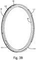
- FIG. 3B is a perspective view of first carbon ring 66 and
- FIG. 3C is a perspective cross-sectional view of first carbon ring 66 and second carbon ring 68 from FIG. 3A .
- first carbon ring 66 includes first tabs 112 and first slots 114
- second carbon ring 68 includes second tabs 116 and second slots 118.
- First tabs 112 extend axially from first rear face 94 of first carbon ring 66, and are radially positioned proximate first outer face 96 of first carbon ring 66.
- First slots 114 extend axially into first rear face 94 of first carbon ring 66 at first outer face 96.
- first carbon ring 66 includes two first tabs 112 and two first slots 114.
- first carbon ring 66 can include a different number of first tabs 112 and first slots 114 than shown in FIGS. 3A-3C .
- first tabs 112 and first slots 114 are arranged circumferentially on first rear face 94 of first carbon ring 66 in alternating fashion such that one of first slots 114 is disposed circumferentially between two first tabs 112.
- Second tabs 116 extend axially forward from second forward face 104 of second carbon ring 68, and are radially positioned proximate second outer face 108 of second carbon ring 68. Second slots 118 extend axially rearward into second forward face 104 of second carbon ring 68 at second outer face 108.
- second carbon ring 68 includes two second tabs 116 and two second slots 118.
- second carbon ring 68 can include a different number of second tabs 116 and second slots 118 than shown in FIGS. 3A-3C .
- Second tabs 116 and second slots 118 are arranged circumferentially on second forward face 104 of second carbon ring 68 in alternating fashion such that one of second slots 118 is disposed circumferentially between two second tabs 116.
- first tabs 112 of first carbon ring 66 extend axially into and mate with second slots 118 of second carbon ring 68.
- second tabs 116 of second carbon ring 66 extend axially into and mate with first slots 114 of first carbon ring 66.
- first carbon ring 66 and second carbon ring 68 are interlocked with one another such that first carbon ring 66 and second carbon ring 68 do not rotate relative to one another about center axis CA more than a few degrees (e.g., ten degrees or less).
- spring cavity 111 is positioned radially inward from both tabs 112 and 116, and radially inward from both slots 114 and 118.
- first carbon ring 66 and second carbon ring 68 are completely symmetrical and identical.
- a manufacturer can produce second carbon ring 68 by manufacturing two copies of first carbon ring 66 and rotating one of the copies to mate the two copies together as first carbon ring 66 and second carbon ring 68.
- first tabs 112 and second tabs 116 are identically sized.
- First slots 114 and second slots 118 are also identically sized.
- Tabs 112 and 116 are circumferentially and axially smaller than slots 114 and 118 so as to ensure that tabs 112 and 116 mate with slots 114 and 118, respectively. As shown in FIG.
- first carbon ring 66 and second carbon ring 68 can each include additional features, such as radial grooves 120, axial grooves 122, and circumferential grooves 124.
- Radial grooves 120, axial grooves 122, and circumferential grooves 124 can direct cooling air that is plumbed into seal assembly 62 around first carbon ring 66 and second carbon ring 68 to help balance the air pressure across seal assembly 62. Balancing the air pressure across seal assembly 62 further helps to reduce nonuniform wear of first carbon ring 66 and second carbon ring 68. While FIG.
- first carbon ring 66 and second carbon ring 68 having identical radial grooves 120, identical axial grooves 122, and identical circumferential grooves 124
- alternative embodiments can include first carbon ring 66 with radial grooves, axial grooves, and circumferential grooves that are different from the grooves of second carbon ring 68.
- first carbon ring 66 and second carbon ring 68 interlock with each other such that first carbon ring 66 and second carbon ring 68 do not rotate relative to one another and wear against one another. Reducing relative movement between first carbon ring 66 and second carbon ring 68 also reduces wear on spring 74 and any other hardware (i.e., spring washers) disposed between first carbon ring 66 and second carbon ring 68.
- first carbon ring 66 and second carbon ring 68 are symmetrical and identical to each other so that two copies of a single part can be used for both rings, thereby reducing manufacturing complexity and cost of seal assembly 62.
- a carbon ring for a seal assembly in a gas turbine engine includes an outer face extending circumferentially around a center axis of the carbon ring.
- the carbon ring also includes an inner face extending around the center axis and disposed radially inward from the outer face.
- a forward face of the carbon ring extends radially between the inner face and the outer face.
- a rear face of the carbon ring extends radially between the inner face and the outer face and is disposed axially opposite the forward face.
- At least one tab extends axially from at least one of the forward face and the rear face.
- the carbon ring of the preceding paragraph can optionally include, additionally and/or alternatively, any one or more of the following features, configurations and/or additional components:
- the carbon ring further comprises at least one slot formed in at least one of the forward face and the rear face;
- the at least one tab is formed on the rear face, the at least one slot is formed on the rear face, and the at least one tab is circumferentially smaller than the at least one slot;
- the at least one tab is axially smaller than the at least one slot.
- a seal assembly in another embodiment, includes a first carbon ring with a tab extending axially from the first carbon ring relative a center axis of the seal assembly.
- the seal assembly also includes a second carbon ring disposed adjacent to the first carbon ring and coaxial with the first carbon ring.
- the second carbon ring includes a slot that extends axially into the second carbon ring. The tab of the first carbon ring mates with the slot of the second carbon ring.
- seal assembly of the preceding paragraph can optionally include, additionally and/or alternatively, any one or more of the following features, configurations and/or additional components:
- a seal assembly for a gas turbine engine in another embodiment, includes an annular front seat positioned on a center axis of the seal assembly and an annular rear seat disposed axially aft of the annular front seat.
- a first carbon ring is positioned axially between the annular front seat and the annular rear seat.
- a second carbon ring is positioned axially between the first carbon ring and the annular rear seat. The first carbon ring rotationally interlocks with the second carbon ring.
- seal assembly of the preceding paragraph can optionally include, additionally and/or alternatively, any one or more of the following features, configurations and/or additional components:
- any relative terms or terms of degree used herein such as “substantially”, “essentially”, “generally”, “approximately”, and the like, should be interpreted in accordance with and subject to any applicable definitions or limits expressly stated herein. In all instances, any relative terms or terms of degree used herein should be interpreted to broadly encompass any relevant disclosed embodiments as well as such ranges or variations as would be understood by a person of ordinary skill in the art in view of the entirety of the present disclosure, such as to encompass ordinary manufacturing tolerance variations, incidental alignment variations, transitory vibrations and sway movements, temporary alignment or shape variations induced by operational conditions, and the like.
Landscapes
- Engineering & Computer Science (AREA)
- General Engineering & Computer Science (AREA)
- Mechanical Engineering (AREA)
- Mechanical Sealing (AREA)
- Sealing Devices (AREA)
- Turbine Rotor Nozzle Sealing (AREA)
Applications Claiming Priority (1)
| Application Number | Priority Date | Filing Date | Title |
|---|---|---|---|
| US15/405,376 US10145255B2 (en) | 2017-01-13 | 2017-01-13 | Constant speed 2 piece ring seal arrangement |
Publications (2)
| Publication Number | Publication Date |
|---|---|
| EP3354945A1 true EP3354945A1 (de) | 2018-08-01 |
| EP3354945B1 EP3354945B1 (de) | 2020-09-02 |
Family
ID=60954901
Family Applications (1)
| Application Number | Title | Priority Date | Filing Date |
|---|---|---|---|
| EP18151059.5A Active EP3354945B1 (de) | 2017-01-13 | 2018-01-10 | Zweiteilige ringdichtungsanordnung mit konstanter geschwindigkeit |
Country Status (2)
| Country | Link |
|---|---|
| US (1) | US10145255B2 (de) |
| EP (1) | EP3354945B1 (de) |
Cited By (2)
| Publication number | Priority date | Publication date | Assignee | Title |
|---|---|---|---|---|
| EP3543566A1 (de) * | 2018-03-22 | 2019-09-25 | United Technologies Corporation | Rampenförmige abstandshalterringdichtung |
| EP3719359A1 (de) * | 2019-04-02 | 2020-10-07 | United Technologies Corporation | Erweiterte lagerringdichtungsanordnung zur verhinderung von einbauschäden |
Families Citing this family (7)
| Publication number | Priority date | Publication date | Assignee | Title |
|---|---|---|---|---|
| US11391179B2 (en) | 2019-02-12 | 2022-07-19 | Pratt & Whitney Canada Corp. | Gas turbine engine with bearing support structure |
| US11346249B2 (en) | 2019-03-05 | 2022-05-31 | Pratt & Whitney Canada Corp. | Gas turbine engine with feed pipe for bearing housing |
| PL3798426T3 (pl) | 2019-09-27 | 2023-04-17 | Pratt & Whitney Canada Corp. | Zespół uszczelki węglowej |
| CN113551039A (zh) * | 2021-08-06 | 2021-10-26 | 中国科学院工程热物理研究所 | 一种用于航空发动机中介轴承腔的自适应石墨密封结构 |
| US11892083B2 (en) | 2022-04-06 | 2024-02-06 | Rtx Corporation | Piston seal ring |
| CN114876584B (zh) * | 2022-05-12 | 2023-05-05 | 中国航发四川燃气涡轮研究院 | 一种“错齿型”涡轮外环连接结构 |
| FR3139853B1 (fr) * | 2022-09-20 | 2024-10-25 | Safran Aircraft Engines | Dispositif d’étanchéité et turbomachine comprenant le dispositif d’étanchéité |
Citations (3)
| Publication number | Priority date | Publication date | Assignee | Title |
|---|---|---|---|---|
| US20150369367A1 (en) * | 2012-12-25 | 2015-12-24 | Eagle Industry Co., Ltd. | Segmented seal |
| US20160010483A1 (en) * | 2013-03-06 | 2016-01-14 | United Technologies Corporation | Seal assembly including a notched seal element for arranging between a stator and a rotor |
| EP3048343A1 (de) * | 2015-01-20 | 2016-07-27 | United Technologies Corporation | Mehrstufige zwischenwellenringdichtung |
Family Cites Families (11)
| Publication number | Priority date | Publication date | Assignee | Title |
|---|---|---|---|---|
| US3784213A (en) * | 1972-06-20 | 1974-01-08 | Innovatex Corp | Rotary face seal assembly |
| US6568686B2 (en) * | 2000-12-05 | 2003-05-27 | Am-Metric Seal, Inc. | Mechanical rotary seal |
| US20040026868A1 (en) * | 2002-08-02 | 2004-02-12 | Dahlheimer John C. | Face seal with secondary seal |
| HUE047968T2 (hu) * | 2003-02-28 | 2020-05-28 | Chesterton A W Co | Kiegyenlített mechanikus tömítõszerelvény |
| US7311307B2 (en) * | 2005-09-29 | 2007-12-25 | Freudenberg-Nok General Partnership | Seal seat assembly with specialized features |
| US7648143B2 (en) * | 2005-10-18 | 2010-01-19 | United Technologies Corporation | Tandem dual element intershaft carbon seal |
| US7793940B2 (en) * | 2006-05-16 | 2010-09-14 | Skf Usa Inc. | Mechanical end face seal with ultrahard face material |
| US20080237995A1 (en) * | 2007-03-30 | 2008-10-02 | Louisiana State University | Mechanical Seal with Superior Thermal Performance |
| US7946590B2 (en) * | 2008-01-17 | 2011-05-24 | United Technologies Corporation | Face seal for gas turbine engine |
| DE102010024291B4 (de) * | 2010-04-23 | 2013-04-18 | Carl Freudenberg Kg | Gleitringdichtung mit rotierendem Gegenring mit exakt definierter Einspannung |
| EP3063379B1 (de) * | 2013-10-28 | 2018-12-05 | United Technologies Corporation | Radiale dichtung mit versetztem aussparungsschnitt |
-
2017
- 2017-01-13 US US15/405,376 patent/US10145255B2/en active Active
-
2018
- 2018-01-10 EP EP18151059.5A patent/EP3354945B1/de active Active
Patent Citations (3)
| Publication number | Priority date | Publication date | Assignee | Title |
|---|---|---|---|---|
| US20150369367A1 (en) * | 2012-12-25 | 2015-12-24 | Eagle Industry Co., Ltd. | Segmented seal |
| US20160010483A1 (en) * | 2013-03-06 | 2016-01-14 | United Technologies Corporation | Seal assembly including a notched seal element for arranging between a stator and a rotor |
| EP3048343A1 (de) * | 2015-01-20 | 2016-07-27 | United Technologies Corporation | Mehrstufige zwischenwellenringdichtung |
Cited By (4)
| Publication number | Priority date | Publication date | Assignee | Title |
|---|---|---|---|---|
| EP3543566A1 (de) * | 2018-03-22 | 2019-09-25 | United Technologies Corporation | Rampenförmige abstandshalterringdichtung |
| US11015715B2 (en) | 2018-03-22 | 2021-05-25 | Raytheon Technologies Corporation | Ramped spacer ring seal |
| EP3719359A1 (de) * | 2019-04-02 | 2020-10-07 | United Technologies Corporation | Erweiterte lagerringdichtungsanordnung zur verhinderung von einbauschäden |
| US11125094B2 (en) | 2019-04-02 | 2021-09-21 | Raytheon Technologies Corporation | Extended pilot ring seal arrangement for installation damage prevention |
Also Published As
| Publication number | Publication date |
|---|---|
| US10145255B2 (en) | 2018-12-04 |
| US20180202304A1 (en) | 2018-07-19 |
| EP3354945B1 (de) | 2020-09-02 |
Similar Documents
| Publication | Publication Date | Title |
|---|---|---|
| EP3354945B1 (de) | Zweiteilige ringdichtungsanordnung mit konstanter geschwindigkeit | |
| EP3196517B1 (de) | Sekundärdichtungsvorrichtung(en) mit ausrichtungslasche(n) | |
| US10208615B2 (en) | Seal shoe for a hydrostatic non-contact seal device | |
| US10563532B2 (en) | Non-contact seal with monolithic/unitary carrier structure | |
| US10961860B2 (en) | Non-contact seal with removal features | |
| EP2546469B1 (de) | Außendichtungsanordnung für eine Turbinenschaufel | |
| US10337621B2 (en) | Hydrostatic non-contact seal with weight reduction pocket | |
| US10487943B2 (en) | Multi-ply seal ring | |
| US10718270B2 (en) | Hydrostatic non-contact seal with dual material | |
| US11761352B2 (en) | Carbon seal spring retention | |
| EP3290755A1 (de) | Schwimmende, kontaktfreie dichtung mit mindestens drei leisten | |
| CN110005545A (zh) | 一种鼠笼弹性支承轴承腔结构 | |
| EP3428489B1 (de) | Hydrostatische berührungslose dichtung mit dichtungsträgerbeseitigung | |
| US10753222B2 (en) | Gas turbine engine blade outer air seal | |
| US20190178381A1 (en) | Face seal arrangement with air load force balance recovery for improved failure mitigation strategies | |
| EP3719359B1 (de) | Erweiterte lagerringdichtungsanordnung zur verhinderung von einbauschäden | |
| US10514102B2 (en) | Intershaft bladelet seal | |
| US11255205B2 (en) | Systems and methods for improving start up wear performance of carbon seals | |
| US12098690B2 (en) | Assembly for an aircraft turbine engine, comprising means for the axial and radial retention of a fan |
Legal Events
| Date | Code | Title | Description |
|---|---|---|---|
| PUAI | Public reference made under article 153(3) epc to a published international application that has entered the european phase |
Free format text: ORIGINAL CODE: 0009012 |
|
| STAA | Information on the status of an ep patent application or granted ep patent |
Free format text: STATUS: THE APPLICATION HAS BEEN PUBLISHED |
|
| AK | Designated contracting states |
Kind code of ref document: A1 Designated state(s): AL AT BE BG CH CY CZ DE DK EE ES FI FR GB GR HR HU IE IS IT LI LT LU LV MC MK MT NL NO PL PT RO RS SE SI SK SM TR |
|
| AX | Request for extension of the european patent |
Extension state: BA ME |
|
| STAA | Information on the status of an ep patent application or granted ep patent |
Free format text: STATUS: REQUEST FOR EXAMINATION WAS MADE |
|
| 17P | Request for examination filed |
Effective date: 20190130 |
|
| RBV | Designated contracting states (corrected) |
Designated state(s): AL AT BE BG CH CY CZ DE DK EE ES FI FR GB GR HR HU IE IS IT LI LT LU LV MC MK MT NL NO PL PT RO RS SE SI SK SM TR |
|
| STAA | Information on the status of an ep patent application or granted ep patent |
Free format text: STATUS: EXAMINATION IS IN PROGRESS |
|
| 17Q | First examination report despatched |
Effective date: 20190723 |
|
| GRAP | Despatch of communication of intention to grant a patent |
Free format text: ORIGINAL CODE: EPIDOSNIGR1 |
|
| STAA | Information on the status of an ep patent application or granted ep patent |
Free format text: STATUS: GRANT OF PATENT IS INTENDED |
|
| INTG | Intention to grant announced |
Effective date: 20200406 |
|
| GRAS | Grant fee paid |
Free format text: ORIGINAL CODE: EPIDOSNIGR3 |
|
| GRAA | (expected) grant |
Free format text: ORIGINAL CODE: 0009210 |
|
| STAA | Information on the status of an ep patent application or granted ep patent |
Free format text: STATUS: THE PATENT HAS BEEN GRANTED |
|
| AK | Designated contracting states |
Kind code of ref document: B1 Designated state(s): AL AT BE BG CH CY CZ DE DK EE ES FI FR GB GR HR HU IE IS IT LI LT LU LV MC MK MT NL NO PL PT RO RS SE SI SK SM TR |
|
| REG | Reference to a national code |
Ref country code: GB Ref legal event code: FG4D |
|
| REG | Reference to a national code |
Ref country code: AT Ref legal event code: REF Ref document number: 1309207 Country of ref document: AT Kind code of ref document: T Effective date: 20200915 Ref country code: CH Ref legal event code: EP |
|
| REG | Reference to a national code |
Ref country code: DE Ref legal event code: R096 Ref document number: 602018007334 Country of ref document: DE |
|
| REG | Reference to a national code |
Ref country code: IE Ref legal event code: FG4D |
|
| REG | Reference to a national code |
Ref country code: LT Ref legal event code: MG4D |
|
| PG25 | Lapsed in a contracting state [announced via postgrant information from national office to epo] |
Ref country code: HR Free format text: LAPSE BECAUSE OF FAILURE TO SUBMIT A TRANSLATION OF THE DESCRIPTION OR TO PAY THE FEE WITHIN THE PRESCRIBED TIME-LIMIT Effective date: 20200902 Ref country code: LT Free format text: LAPSE BECAUSE OF FAILURE TO SUBMIT A TRANSLATION OF THE DESCRIPTION OR TO PAY THE FEE WITHIN THE PRESCRIBED TIME-LIMIT Effective date: 20200902 Ref country code: FI Free format text: LAPSE BECAUSE OF FAILURE TO SUBMIT A TRANSLATION OF THE DESCRIPTION OR TO PAY THE FEE WITHIN THE PRESCRIBED TIME-LIMIT Effective date: 20200902 Ref country code: GR Free format text: LAPSE BECAUSE OF FAILURE TO SUBMIT A TRANSLATION OF THE DESCRIPTION OR TO PAY THE FEE WITHIN THE PRESCRIBED TIME-LIMIT Effective date: 20201203 Ref country code: BG Free format text: LAPSE BECAUSE OF FAILURE TO SUBMIT A TRANSLATION OF THE DESCRIPTION OR TO PAY THE FEE WITHIN THE PRESCRIBED TIME-LIMIT Effective date: 20201202 Ref country code: SE Free format text: LAPSE BECAUSE OF FAILURE TO SUBMIT A TRANSLATION OF THE DESCRIPTION OR TO PAY THE FEE WITHIN THE PRESCRIBED TIME-LIMIT Effective date: 20200902 Ref country code: NO Free format text: LAPSE BECAUSE OF FAILURE TO SUBMIT A TRANSLATION OF THE DESCRIPTION OR TO PAY THE FEE WITHIN THE PRESCRIBED TIME-LIMIT Effective date: 20201202 |
|
| REG | Reference to a national code |
Ref country code: NL Ref legal event code: MP Effective date: 20200902 |
|
| REG | Reference to a national code |
Ref country code: AT Ref legal event code: MK05 Ref document number: 1309207 Country of ref document: AT Kind code of ref document: T Effective date: 20200902 |
|
| PG25 | Lapsed in a contracting state [announced via postgrant information from national office to epo] |
Ref country code: PL Free format text: LAPSE BECAUSE OF FAILURE TO SUBMIT A TRANSLATION OF THE DESCRIPTION OR TO PAY THE FEE WITHIN THE PRESCRIBED TIME-LIMIT Effective date: 20200902 Ref country code: LV Free format text: LAPSE BECAUSE OF FAILURE TO SUBMIT A TRANSLATION OF THE DESCRIPTION OR TO PAY THE FEE WITHIN THE PRESCRIBED TIME-LIMIT Effective date: 20200902 Ref country code: RS Free format text: LAPSE BECAUSE OF FAILURE TO SUBMIT A TRANSLATION OF THE DESCRIPTION OR TO PAY THE FEE WITHIN THE PRESCRIBED TIME-LIMIT Effective date: 20200902 |
|
| RAP2 | Party data changed (patent owner data changed or rights of a patent transferred) |
Owner name: RAYTHEON TECHNOLOGIES CORPORATION |
|
| PG25 | Lapsed in a contracting state [announced via postgrant information from national office to epo] |
Ref country code: SM Free format text: LAPSE BECAUSE OF FAILURE TO SUBMIT A TRANSLATION OF THE DESCRIPTION OR TO PAY THE FEE WITHIN THE PRESCRIBED TIME-LIMIT Effective date: 20200902 Ref country code: EE Free format text: LAPSE BECAUSE OF FAILURE TO SUBMIT A TRANSLATION OF THE DESCRIPTION OR TO PAY THE FEE WITHIN THE PRESCRIBED TIME-LIMIT Effective date: 20200902 Ref country code: RO Free format text: LAPSE BECAUSE OF FAILURE TO SUBMIT A TRANSLATION OF THE DESCRIPTION OR TO PAY THE FEE WITHIN THE PRESCRIBED TIME-LIMIT Effective date: 20200902 Ref country code: PT Free format text: LAPSE BECAUSE OF FAILURE TO SUBMIT A TRANSLATION OF THE DESCRIPTION OR TO PAY THE FEE WITHIN THE PRESCRIBED TIME-LIMIT Effective date: 20210104 Ref country code: CZ Free format text: LAPSE BECAUSE OF FAILURE TO SUBMIT A TRANSLATION OF THE DESCRIPTION OR TO PAY THE FEE WITHIN THE PRESCRIBED TIME-LIMIT Effective date: 20200902 |
|
| PG25 | Lapsed in a contracting state [announced via postgrant information from national office to epo] |
Ref country code: IS Free format text: LAPSE BECAUSE OF FAILURE TO SUBMIT A TRANSLATION OF THE DESCRIPTION OR TO PAY THE FEE WITHIN THE PRESCRIBED TIME-LIMIT Effective date: 20210102 Ref country code: ES Free format text: LAPSE BECAUSE OF FAILURE TO SUBMIT A TRANSLATION OF THE DESCRIPTION OR TO PAY THE FEE WITHIN THE PRESCRIBED TIME-LIMIT Effective date: 20200902 Ref country code: AL Free format text: LAPSE BECAUSE OF FAILURE TO SUBMIT A TRANSLATION OF THE DESCRIPTION OR TO PAY THE FEE WITHIN THE PRESCRIBED TIME-LIMIT Effective date: 20200902 Ref country code: AT Free format text: LAPSE BECAUSE OF FAILURE TO SUBMIT A TRANSLATION OF THE DESCRIPTION OR TO PAY THE FEE WITHIN THE PRESCRIBED TIME-LIMIT Effective date: 20200902 |
|
| REG | Reference to a national code |
Ref country code: DE Ref legal event code: R097 Ref document number: 602018007334 Country of ref document: DE |
|
| PG25 | Lapsed in a contracting state [announced via postgrant information from national office to epo] |
Ref country code: SK Free format text: LAPSE BECAUSE OF FAILURE TO SUBMIT A TRANSLATION OF THE DESCRIPTION OR TO PAY THE FEE WITHIN THE PRESCRIBED TIME-LIMIT Effective date: 20200902 |
|
| PLBE | No opposition filed within time limit |
Free format text: ORIGINAL CODE: 0009261 |
|
| STAA | Information on the status of an ep patent application or granted ep patent |
Free format text: STATUS: NO OPPOSITION FILED WITHIN TIME LIMIT |
|
| 26N | No opposition filed |
Effective date: 20210603 |
|
| PG25 | Lapsed in a contracting state [announced via postgrant information from national office to epo] |
Ref country code: MC Free format text: LAPSE BECAUSE OF FAILURE TO SUBMIT A TRANSLATION OF THE DESCRIPTION OR TO PAY THE FEE WITHIN THE PRESCRIBED TIME-LIMIT Effective date: 20200902 Ref country code: SI Free format text: LAPSE BECAUSE OF FAILURE TO SUBMIT A TRANSLATION OF THE DESCRIPTION OR TO PAY THE FEE WITHIN THE PRESCRIBED TIME-LIMIT Effective date: 20200902 Ref country code: DK Free format text: LAPSE BECAUSE OF FAILURE TO SUBMIT A TRANSLATION OF THE DESCRIPTION OR TO PAY THE FEE WITHIN THE PRESCRIBED TIME-LIMIT Effective date: 20200902 |
|
| REG | Reference to a national code |
Ref country code: CH Ref legal event code: PL |
|
| PG25 | Lapsed in a contracting state [announced via postgrant information from national office to epo] |
Ref country code: LU Free format text: LAPSE BECAUSE OF NON-PAYMENT OF DUE FEES Effective date: 20210110 |
|
| REG | Reference to a national code |
Ref country code: BE Ref legal event code: MM Effective date: 20210131 |
|
| PG25 | Lapsed in a contracting state [announced via postgrant information from national office to epo] |
Ref country code: IT Free format text: LAPSE BECAUSE OF FAILURE TO SUBMIT A TRANSLATION OF THE DESCRIPTION OR TO PAY THE FEE WITHIN THE PRESCRIBED TIME-LIMIT Effective date: 20200902 |
|
| PG25 | Lapsed in a contracting state [announced via postgrant information from national office to epo] |
Ref country code: CH Free format text: LAPSE BECAUSE OF NON-PAYMENT OF DUE FEES Effective date: 20210131 Ref country code: LI Free format text: LAPSE BECAUSE OF NON-PAYMENT OF DUE FEES Effective date: 20210131 |
|
| PG25 | Lapsed in a contracting state [announced via postgrant information from national office to epo] |
Ref country code: IE Free format text: LAPSE BECAUSE OF NON-PAYMENT OF DUE FEES Effective date: 20210110 |
|
| PG25 | Lapsed in a contracting state [announced via postgrant information from national office to epo] |
Ref country code: BE Free format text: LAPSE BECAUSE OF NON-PAYMENT OF DUE FEES Effective date: 20210131 |
|
| P01 | Opt-out of the competence of the unified patent court (upc) registered |
Effective date: 20230520 |
|
| PG25 | Lapsed in a contracting state [announced via postgrant information from national office to epo] |
Ref country code: NL Free format text: LAPSE BECAUSE OF NON-PAYMENT OF DUE FEES Effective date: 20200923 Ref country code: CY Free format text: LAPSE BECAUSE OF FAILURE TO SUBMIT A TRANSLATION OF THE DESCRIPTION OR TO PAY THE FEE WITHIN THE PRESCRIBED TIME-LIMIT Effective date: 20200902 |
|
| PG25 | Lapsed in a contracting state [announced via postgrant information from national office to epo] |
Ref country code: HU Free format text: LAPSE BECAUSE OF FAILURE TO SUBMIT A TRANSLATION OF THE DESCRIPTION OR TO PAY THE FEE WITHIN THE PRESCRIBED TIME-LIMIT; INVALID AB INITIO Effective date: 20180110 |
|
| PG25 | Lapsed in a contracting state [announced via postgrant information from national office to epo] |
Ref country code: MK Free format text: LAPSE BECAUSE OF FAILURE TO SUBMIT A TRANSLATION OF THE DESCRIPTION OR TO PAY THE FEE WITHIN THE PRESCRIBED TIME-LIMIT Effective date: 20200902 |
|
| PG25 | Lapsed in a contracting state [announced via postgrant information from national office to epo] |
Ref country code: TR Free format text: LAPSE BECAUSE OF FAILURE TO SUBMIT A TRANSLATION OF THE DESCRIPTION OR TO PAY THE FEE WITHIN THE PRESCRIBED TIME-LIMIT Effective date: 20200902 |
|
| PG25 | Lapsed in a contracting state [announced via postgrant information from national office to epo] |
Ref country code: MT Free format text: LAPSE BECAUSE OF FAILURE TO SUBMIT A TRANSLATION OF THE DESCRIPTION OR TO PAY THE FEE WITHIN THE PRESCRIBED TIME-LIMIT Effective date: 20200902 |
|
| REG | Reference to a national code |
Ref country code: DE Ref legal event code: R081 Ref document number: 602018007334 Country of ref document: DE Owner name: RTX CORPORATION (N.D.GES.D. STAATES DELAWARE),, US Free format text: FORMER OWNER: UNITED TECHNOLOGIES CORPORATION, FARMINGTON, CONN., US |
|
| PGFP | Annual fee paid to national office [announced via postgrant information from national office to epo] |
Ref country code: GB Payment date: 20251217 Year of fee payment: 9 |
|
| PGFP | Annual fee paid to national office [announced via postgrant information from national office to epo] |
Ref country code: FR Payment date: 20251218 Year of fee payment: 9 |
|
| PGFP | Annual fee paid to national office [announced via postgrant information from national office to epo] |
Ref country code: DE Payment date: 20251217 Year of fee payment: 9 |