EP3354954A1 - Procédé de formation d'un embout de tuyau sur un tube - Google Patents
Procédé de formation d'un embout de tuyau sur un tube Download PDFInfo
- Publication number
- EP3354954A1 EP3354954A1 EP17153702.0A EP17153702A EP3354954A1 EP 3354954 A1 EP3354954 A1 EP 3354954A1 EP 17153702 A EP17153702 A EP 17153702A EP 3354954 A1 EP3354954 A1 EP 3354954A1
- Authority
- EP
- European Patent Office
- Prior art keywords
- tube
- hose
- collar
- perforated disc
- pipe
- Prior art date
- Legal status (The legal status is an assumption and is not a legal conclusion. Google has not performed a legal analysis and makes no representation as to the accuracy of the status listed.)
- Withdrawn
Links
Images



Classifications
-
- F—MECHANICAL ENGINEERING; LIGHTING; HEATING; WEAPONS; BLASTING
- F16—ENGINEERING ELEMENTS AND UNITS; GENERAL MEASURES FOR PRODUCING AND MAINTAINING EFFECTIVE FUNCTIONING OF MACHINES OR INSTALLATIONS; THERMAL INSULATION IN GENERAL
- F16L—PIPES; JOINTS OR FITTINGS FOR PIPES; SUPPORTS FOR PIPES, CABLES OR PROTECTIVE TUBING; MEANS FOR THERMAL INSULATION IN GENERAL
- F16L33/00—Arrangements for connecting hoses to rigid members; Rigid hose-connectors, i.e. single members engaging both hoses
- F16L33/20—Undivided rings, sleeves, or like members contracted on the hose or expanded inside the hose by means of tools; Arrangements using such members
- F16L33/207—Undivided rings, sleeves, or like members contracted on the hose or expanded inside the hose by means of tools; Arrangements using such members only a sleeve being contracted on the hose
- F16L33/2071—Undivided rings, sleeves, or like members contracted on the hose or expanded inside the hose by means of tools; Arrangements using such members only a sleeve being contracted on the hose the sleeve being a separate connecting member
- F16L33/2073—Undivided rings, sleeves, or like members contracted on the hose or expanded inside the hose by means of tools; Arrangements using such members only a sleeve being contracted on the hose the sleeve being a separate connecting member directly connected to the rigid member
- F16L33/2076—Undivided rings, sleeves, or like members contracted on the hose or expanded inside the hose by means of tools; Arrangements using such members only a sleeve being contracted on the hose the sleeve being a separate connecting member directly connected to the rigid member by plastic deformation
-
- B—PERFORMING OPERATIONS; TRANSPORTING
- B21—MECHANICAL METAL-WORKING WITHOUT ESSENTIALLY REMOVING MATERIAL; PUNCHING METAL
- B21D—WORKING OR PROCESSING OF SHEET METAL OR METAL TUBES, RODS OR PROFILES WITHOUT ESSENTIALLY REMOVING MATERIAL; PUNCHING METAL
- B21D39/00—Application of procedures in order to connect objects or parts, e.g. coating with sheet metal otherwise than by plating; Tube expanders
- B21D39/06—Application of procedures in order to connect objects or parts, e.g. coating with sheet metal otherwise than by plating; Tube expanders of tubes in openings, e.g. rolling-in
Definitions
- the invention relates to a method for forming a hose connection at one end of a pipe. Moreover, the invention relates to a method for connecting a hose to the tubular end of the tube according to the invention and a corresponding tube with the said hose connection and optionally mounted hose.
- Tubes with hose-side end are well known in the art. In the simplest case, one end of the hose is simply pushed onto a hose end of a pipe.
- hose end of a pipe For highly loaded tube / hose connections, as required in particular for hydraulic applications, it is also known to provide a tubular connection area to a tube, the tube then spaced from its tube-side opening has two axially spaced radially outwardly extending elevations to a Position the compression sleeve in a groove between the two elevations and crimp it with the pushed-on hose.
- a first production method provides that initially a pipe section and a hose part of the pipe are manufactured separately be and subsequently, z. B. by soldering, are connected to the entire pipeline. The necessary elevations for the hose connection are then prefabricated in the hose part. Overall, this first manufacturing process is very expensive because the production of two items requires a lot of manual preparation and the subsequent soldering or welding is also very time consuming and thus labor intensive.
- a short pipe socket also called fitting
- This second production method is also expensive because it requires a very expensive machine, in particular a multi-spindle turning machine.
- the entire valve can be made of a piece of pipe, the two increases in the hose connection area are traditionally made by sequential cold forming, in particular compression. Also this pipe can be bent later outside the pipe connection area, if necessary.
- This production variant is more favorable in comparison to the aforementioned production method, but in particular the third production method has the following disadvantages:
- the pipe In hydraulic applications, the pipe is subjected to constant pressure load changes and bending load changes, which act in particular in the radial direction.
- the tubes traditionally manufactured in the manner described in the last paragraph have been found to often rupture at least a first of the two elevations due to said load changes. The reason for this is to be seen in the fact that in these radial elevations, in particular if their outer diameter is greater than 1.5 times the outer diameter of the tube, the forming base is very large. The thinning and strain hardening associated with the large deformation leads to a no longer sufficient Compressive strength of the tube. It can then come to hydraulic leaks or even hose breaks and thus total failure of the component.
- the present invention seeks to develop a known method for forming a hose connection at one end of a tube to the extent that at least one of the required for the hose connection increases in the wall of the tube is made more stable in that they too strong and frequent pressure load changes or bending load changes can withstand.
- a perforated disc is pushed onto a predetermined axial position on the tube end and axially fixed there by beads in front of and behind the perforated disc.
- the formation of the beads represents a significantly lower material load for the wall of the tube than the known from the prior art training of said surveys, because the beads each have only a substantially smaller outer diameter than the surveys.
- the tube is therefore strong in the field of perforated disc and in particular it can withstand pressure load changes or bending load changes well.
- the inventive method described is inexpensive.
- a mandrel is pushed through the tube whose outer diameter is greater than the inner diameter of the tube, whereby the tube expands and before and behind the perforated disc in each case for the formation of one of Beads comes.
- the beads can be introduced in front of and behind the perforated disc with the help of other (cold) forming process in the tube, for example by upsetting.
- a second survey d. H. a radially outwardly rising collar in the wall of the tube required.
- the outer diameter of the second elevation is preferably less than the outer diameter of the first elevation, d. H. the perforated disc.
- the outer diameter is so small and the bending radii and the axial extent of the second survey so large that the production of the second survey by known cold forming in individual cases does not lead to a strong reduction in the compressive strength of the tube.
- the second survey is to be arranged between a hose-side opening of the tube and the perforated disc at a predetermined axial distance from the perforated disc. In this way, a circumferential groove between the perforated disc and the collar, in which later a Verpresshülse is radially compressed.
- the perforated disc serves only as a stop for a later to be mounted compression sleeve. In the axial direction, it must only be firmly positioned, but not absorb large forces, but the beads are sufficient. During later operation of the pipe / hose connection, the pipe area where the perforated disk is positioned must only be sufficiently pressure-resistant, which is ensured by the claimed assembly method. In contrast, the second survey must not only be pressure-resistant, but if necessary, can absorb large axial forces. For this purpose, the formation of the second increase by known cold forming is better suited.
- the hose connection region between the tube-side opening of the tube and the radially rising collar still has a tooth profile for a better grip of the later deferred hose.
- the introduction of the federal government and / or the tooth profile according to the invention for example, by a multi-stage axial cold forming process, including upsetting and / or rolling.
- the above-mentioned object is further achieved by a method for connecting a hose to the tube-side end of the tube, wherein the formation of a hose connection region at the tube-side end of the tube takes place by the method according to the invention.
- the compression sleeve is then first pushed onto the hose connection area up to the perforated disk, wherein the perforated disk forms a stop for the compression sleeve. It then takes place the actual sliding of the hose on the hose connection area of the pipe up to or on the collar under the compression sleeve. Finally, the compression sleeve is pressed radially into the groove between the perforated disc and the collar and at the same time the compression sleeve is also pressed with the deferred end of the tube.
- the tube / hose connection thus obtained according to the invention is characterized by a particularly firm hold between pipe or fitting and hose. It shows a very good sealing performance, without the inner tube layer has been damaged.
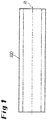
- FIG. 1 shows a tube 100 in its initial state with its longitudinal axis R, which extends in the axial direction of the tube.
- this tube 100 is clamped in a holding tool 210 so that its tube-side end remains free or outside.
- a perforated disc 120 is pushed, which in FIG. 2 abuts on the holding tool 210.
- the holding tool 210 defines a predetermined axial position for the perforated disc 120.
- a push cylinder 230 is pushed, in which a mandrel 220 is axially guided.
- the mandrel 220 has an outer diameter that is greater than the original inner diameter of the tube.
- the mandrel 220 is pushed into the tube 100 by means of the spinning cylinder 230, thereby expanding the tube due to the larger outer diameter of the mandrel.
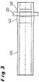
- These expansions also take place in front of and behind the slotted perforated disc, where they lead to the formation of the beads 110 and 140; please refer FIG. 3 , Due to the formation of these beads before and behind the perforated disc 120, this is fixed axially.
- FIGS. 4 to 8 relate to the introduction of a radially outwardly rising collar 130 in the wall of the tube.
- a first tool 240 is connected between the holding tool 210 and the spinning cylinder 230, wherein the first tool 240 is contoured on its inside so that it allows the formation of an enlarged bead 140 in front of the perforated disc 120.
- the formation of this enlarged bead is then carried out by again pushing through a mandrel through the tube.
- the formation of the second elevation 130 by compression of the tube by means of the mandrel 220 wherein it is formed so long that it initially extends to below or up to the height of the perforated disc. This is important to prevent the wall of the tube would deform in the event of compression at an undesirable location, especially in the nearer region of the perforated disc.
- the outer diameter of the second elevation 130 can subsequently be enlarged in a second upsetting process; For this purpose, then a shortened mandrel 220, which only has to extend to the second survey.
- the perforated disc 120 is axially fixed at a predetermined position with respect to the tube-side opening 160 of the tube.
- the second elevation 130 is formed at a likewise predetermined axial distance a.
- the outer diameter of this second elevation 130 is smaller than the outer diameter 120 of the perforated disc.
- the outer diameter of the second elevation 130 is only selected to be so large that the cold forming carried out for its production does not lead to an unacceptably high reduction in the compressive strength of the tube 100.
- the outer diameter of the second elevation 130 is matched to the thickness of the hose to be pushed.
- the difference between the outer diameter of the second elevation 130 and the outer diameter of the tube 100 corresponds approximately to the thickness of the wall of the fauxschiebenden hose.
- FIG. 6 shows three roller burnishing rollers 172 for introducing a tooth profile in the hose end of the tube.
- the tooth profile 170 is disposed between the tube-side opening 160 of the tube and the collar 130.
- FIG. 7 finally shows the tube 100 with inventively designed hose connection region 105.
- the hose-side end of the tube is bounded on the one hand by the perforated disc 120 and on the other hand by the hose side Opening 160.
- the collar 130 can be seen in said predetermined distance a from the perforated disc, and a tooth profile 170 can be seen between the collar and the opening 160.
- FIG. 7 to recognize a hose 400, which is pushed up to the collar 130 on the hose side end.
- the compression sleeve 300 is to recognize in the unpressed state.
- FIG. 8 shows the tube-hose connection according to FIG. 7 , but in pressed condition. Specifically, the compression sleeve 300 is pressed into the groove between the perforated disc 120 and the collar 130 and at the same time the compression sleeve 300 is pressed or crimped in the region of the tooth profile 170 with the pushed end of the tube 400.
Landscapes
- Engineering & Computer Science (AREA)
- Mechanical Engineering (AREA)
- General Engineering & Computer Science (AREA)
- Forging (AREA)
Priority Applications (1)
| Application Number | Priority Date | Filing Date | Title |
|---|---|---|---|
| EP17153702.0A EP3354954A1 (fr) | 2017-01-30 | 2017-01-30 | Procédé de formation d'un embout de tuyau sur un tube |
Applications Claiming Priority (1)
| Application Number | Priority Date | Filing Date | Title |
|---|---|---|---|
| EP17153702.0A EP3354954A1 (fr) | 2017-01-30 | 2017-01-30 | Procédé de formation d'un embout de tuyau sur un tube |
Publications (1)
| Publication Number | Publication Date |
|---|---|
| EP3354954A1 true EP3354954A1 (fr) | 2018-08-01 |
Family
ID=57914885
Family Applications (1)
| Application Number | Title | Priority Date | Filing Date |
|---|---|---|---|
| EP17153702.0A Withdrawn EP3354954A1 (fr) | 2017-01-30 | 2017-01-30 | Procédé de formation d'un embout de tuyau sur un tube |
Country Status (1)
| Country | Link |
|---|---|
| EP (1) | EP3354954A1 (fr) |
Citations (4)
| Publication number | Priority date | Publication date | Assignee | Title |
|---|---|---|---|---|
| US3589752A (en) * | 1969-07-28 | 1971-06-29 | Caterpillar Tractor Co | Mechanical joined hose coupling of extruded components |
| DE4003379A1 (de) * | 1989-02-06 | 1990-08-09 | Oetiker Hans Maschinen | Verfahren zum befestigen eines schlauches an einem nippel und eine schlauchverbindung, hergestellt nach diesem verfahren |
| DE19818085A1 (de) * | 1998-04-23 | 1999-10-28 | Hartmut Schmitz | Verfahren zur Herstellung einer Verbindung eines Schlauches, insbesondere eines Druckschlauches mit einer Armatur, sowie nach dem Verfahren hergestellte Schlauchverbindung |
| DE69809823T2 (de) * | 1997-02-14 | 2003-11-06 | Cintrag-Industrie, S.A. | Verfahren zum Verbinden eines Schlauches mit einem Rohr, Kupplung und Befestigungsring zum Durchführen dieses Verfahrens |
-
2017
- 2017-01-30 EP EP17153702.0A patent/EP3354954A1/fr not_active Withdrawn
Patent Citations (4)
| Publication number | Priority date | Publication date | Assignee | Title |
|---|---|---|---|---|
| US3589752A (en) * | 1969-07-28 | 1971-06-29 | Caterpillar Tractor Co | Mechanical joined hose coupling of extruded components |
| DE4003379A1 (de) * | 1989-02-06 | 1990-08-09 | Oetiker Hans Maschinen | Verfahren zum befestigen eines schlauches an einem nippel und eine schlauchverbindung, hergestellt nach diesem verfahren |
| DE69809823T2 (de) * | 1997-02-14 | 2003-11-06 | Cintrag-Industrie, S.A. | Verfahren zum Verbinden eines Schlauches mit einem Rohr, Kupplung und Befestigungsring zum Durchführen dieses Verfahrens |
| DE19818085A1 (de) * | 1998-04-23 | 1999-10-28 | Hartmut Schmitz | Verfahren zur Herstellung einer Verbindung eines Schlauches, insbesondere eines Druckschlauches mit einer Armatur, sowie nach dem Verfahren hergestellte Schlauchverbindung |
Similar Documents
| Publication | Publication Date | Title |
|---|---|---|
| DE4003379C2 (de) | Hochdruck-Schlauchverbindung und Verfahren zu ihrer Herstellung | |
| DE3412877C2 (fr) | ||
| DE10120392B4 (de) | Verfahren zum Herstellen von rotationssymmetrischen Bauteilen | |
| EP2322831B1 (fr) | Raccord de serrage pour tuyaux, notamment pour la compression de tuyaux multicouche, et procédé d'application d'un raccord de serrage pour tuyaux | |
| EP1707861A1 (fr) | Raccord et son procédé de fabrication | |
| DE102006021843A1 (de) | Abstandsniet, Nietverbindung und Verfahren zu ihrer Herstellung | |
| EP2205371B1 (fr) | Procédé pour fabriquer des systèmes à double tube | |
| DE102009031465A1 (de) | Mehrkanalrohr sowie ein Verfahren zu seiner Herstellung | |
| EP0085388B1 (fr) | Procédé de fabrication d'un manchon métallique à partir d'une pièce tubulaire cylindrique | |
| EP2446980B1 (fr) | Tuyau d'échafaudage et procédé destiné au traitement d'extrémités de tuyaux | |
| EP2706276B1 (fr) | Tube renforcé sur la paroi intérieure et son procédé de fabrication | |
| DE19941577C2 (de) | Rohrverbindung und Verfahren zu ihrer Herstellung | |
| DE102012003146B4 (de) | Schlauchverbindung und Verfahren zur Herstellung einer Schlauchverbindung | |
| DE202007010417U1 (de) | Vorrichtung zur Aufnahme einer Hydraulikflüssigkeit innerhalb eines Kraftfahrzeug-Hydraliksystems | |
| EP2699832B1 (fr) | Procédé de fabrication d'une extremite de raccordement d'un tuyau | |
| DE102008057448A1 (de) | Rohrleitungsverbindung und Verfahren zu deren Herstellung | |
| DE102015005236A1 (de) | Verfahren zur Montage eines Verstellelements eines Fahrzeugsitzuntergestells und Vorrichtung zur Durchführung des Verfahrens sowie Schwächungsstempel | |
| DE69809823T3 (de) | Verfahren zum Verbinden eines Schlauches mit einem Rohr, Kupplung und Befestigungsring zum Durchführen dieses Verfahrens | |
| DE102016105194A1 (de) | Verfahren zur Herstellung einer Pressverbindung | |
| DE202015003006U1 (de) | Vorrichtung zur Montage eines Verstellelements eines Fahrzeugsitzuntergestells und Schwächungsstempel | |
| EP4607074A1 (fr) | Raccord fileté pour tuyaux, utilisation d'un tel raccord fileté pour tuyaux et procédé de fabrication d'un raccord entre un tuyau et un tel raccord fileté | |
| DE9102761U1 (de) | Preßverbindung | |
| DE102009037245A1 (de) | Verfahren zum Vernieten zweier Werkstücke, Niet- und Werkzeug zum Verformen des Niets | |
| DE102015120447A1 (de) | Hydraulikarmatur und Herstellungsverfahren für eine derartige Armatur | |
| DE102014107602A1 (de) | Schiebepressring/Werkzeugteil zum Verbinden von Rohren |
Legal Events
| Date | Code | Title | Description |
|---|---|---|---|
| PUAI | Public reference made under article 153(3) epc to a published international application that has entered the european phase |
Free format text: ORIGINAL CODE: 0009012 |
|
| AK | Designated contracting states |
Kind code of ref document: A1 Designated state(s): AL AT BE BG CH CY CZ DE DK EE ES FI FR GB GR HR HU IE IS IT LI LT LU LV MC MK MT NL NO PL PT RO RS SE SI SK SM TR |
|
| AX | Request for extension of the european patent |
Extension state: BA ME |
|
| STAA | Information on the status of an ep patent application or granted ep patent |
Free format text: STATUS: THE APPLICATION IS DEEMED TO BE WITHDRAWN |
|
| 18D | Application deemed to be withdrawn |
Effective date: 20190202 |