EP3354969B1 - Dispositif d'éclairage destiné à des véhicules ayant des modules d'éclairage rotatifs - Google Patents
Dispositif d'éclairage destiné à des véhicules ayant des modules d'éclairage rotatifs Download PDFInfo
- Publication number
- EP3354969B1 EP3354969B1 EP17154079.2A EP17154079A EP3354969B1 EP 3354969 B1 EP3354969 B1 EP 3354969B1 EP 17154079 A EP17154079 A EP 17154079A EP 3354969 B1 EP3354969 B1 EP 3354969B1
- Authority
- EP
- European Patent Office
- Prior art keywords
- masking element
- lighting
- transparent cover
- lighting modules
- masking
- Prior art date
- Legal status (The legal status is an assumption and is not a legal conclusion. Google has not performed a legal analysis and makes no representation as to the accuracy of the status listed.)
- Active
Links
Images


Classifications
-
- F—MECHANICAL ENGINEERING; LIGHTING; HEATING; WEAPONS; BLASTING
- F21—LIGHTING
- F21S—NON-PORTABLE LIGHTING DEVICES; SYSTEMS THEREOF; VEHICLE LIGHTING DEVICES SPECIALLY ADAPTED FOR VEHICLE EXTERIORS
- F21S41/00—Illuminating devices specially adapted for vehicle exteriors, e.g. headlamps
- F21S41/50—Illuminating devices specially adapted for vehicle exteriors, e.g. headlamps characterised by aesthetic components not otherwise provided for, e.g. decorative trim, partition walls or covers
-
- F—MECHANICAL ENGINEERING; LIGHTING; HEATING; WEAPONS; BLASTING
- F21—LIGHTING
- F21S—NON-PORTABLE LIGHTING DEVICES; SYSTEMS THEREOF; VEHICLE LIGHTING DEVICES SPECIALLY ADAPTED FOR VEHICLE EXTERIORS
- F21S41/00—Illuminating devices specially adapted for vehicle exteriors, e.g. headlamps
- F21S41/60—Illuminating devices specially adapted for vehicle exteriors, e.g. headlamps characterised by a variable light distribution
- F21S41/67—Illuminating devices specially adapted for vehicle exteriors, e.g. headlamps characterised by a variable light distribution by acting on reflectors
- F21S41/675—Illuminating devices specially adapted for vehicle exteriors, e.g. headlamps characterised by a variable light distribution by acting on reflectors by moving reflectors
Definitions
- the present invention relates to a lighting device equipped with one or more rotating lighting modules as well as with at least one stationary lighting module.
- Lighting devices for vehicles provided with multiple optical functions obtained by using one or more rotating elements are known in the art.
- EP2957822 discloses a lighting device including a rotating module including a fixed reflector, a fixed light source aligned with an axis, and a couple of opposite screens rotating around the axis under the action of a motor actuator; the two screens embody two lenses, e.g. one provided with prisms and one neutral, in order to change the light distribution provided by the light source and the reflector when each of the screens is selectively rotated in front of the reflector.
- EP2902701 discloses a rotating lighting module wherein the light source is a LED and the reflector consists of a rotating support having two opposite faces, one constituting the reflector and the other realizing a second function, e.g. an aspect function; a fixed motor rotates the support with respect to the fixed light source in order to bring selectively the two faces on the front side of the device facing toward the direction of motion of the vehicle; the support also bears at its opposite faces two light guides operatively associated with a second LED DE 10 2007 047413 A1 discloses another lighting device of the prior art.
- the lighting devices of the prior art need actuation mechanisms to operate the rotating modules and to leave the rotating parts to be free to rotate.
- those mechanisms may be seen from the outside due to the fact that the modern lighting devices are generally provided with outer transparent covers/lens through which the lighting modules are visible.
- the lighting devices need therefore to be provided with an aesthetic mask to cover the actuating mechanisms.
- the presence of the aesthetic mask renders the mounting of the lighting device and its maintenance (e.g. to replace the light sources) quite complex and difficult.
- the object of the present invention is to provide a lighting device for vehicles provided with lighting modules therein which are visible from the outside that is compact, simple and cost-effective in construction and highly reliable, while ensuring at the same time to hide in an efficient manner the inner mechanisms of the lighting device, e.g. for actuating one or more rotating lighting modules, without interfering with the optical functions of the lighting modules.
- a lighting device for vehicles having the features set out in the appended claims.
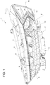
- reference numeral 1 indicates as a whole a lighting device for vehicles consisting, in the non-limiting embodiment shown, in a vehicle headlight, which is only in part and only schematically shown. It is however to be intended that what will be described can be applied to any vehicle lighting device.
- the lighting device 1 comprises a generally cup-shaped housing body 2 designed to be mounted on a vehicle, known and not shown for sake of simplicity.
- Housing body 2 is made of synthetic plastic material by injection molding and has a front inlet opening 3 in use facing opposite to the vehicle and towards a driving or march direction of the vehicle, closed by a transparent cover 4, preferably consisting in a transparent lens not provided with optical functions ("terse" lens).
- the housing body 2 carries at the interior thereof at least one (or more) first lighting module 5, which is in the embodiment shown the main lighting module of the lighting device 1, e.g. is a cross-beam light or high beam light, and, in the preferred embodiment shown, a plurality, preferably three, of second lighting modules 6, which are e.g. secondary lighting modules designed to provide additional optical functions, all together or singularly.
- first lighting module 5 which is in the embodiment shown the main lighting module of the lighting device 1, e.g. is a cross-beam light or high beam light, and, in the preferred embodiment shown, a plurality, preferably three, of second lighting modules 6, which are e.g. secondary lighting modules designed to provide additional optical functions, all together or singularly.
- the lighting modules 5,6 are all visible from the outside through the inlet opening 3 and the transparent cover 4, and are arranged side by side facing the inlet opening 3.
- the lighting modules 5,6 are spaced apart from the inlet opening 3 so that the lighting device 1 also comprises an aesthetic mask 7 to cover a first gap 8 between the transparent cover 4 and the lighting modules 5, 6.
- the first gap 8 extends in a substantially horizontal direction and along the full width of the inlet opening 3, transverse an optical axis OA ( figure 2 ) of the first (main) lighting module 5, which optical axis is oriented in use in the driving direction of the vehicle.
- the aesthetic mask 7 comprises a first masking element 9 which is connected integral to and rigid with an inner surface 10 of the transparent cover 4 facing towards the lighting modules 5,6.
- the first masking element 9 overhangingly protrudes from the inner surface 10 of the transparent cover 3 towards the lighting modules 5,6 to such an extent to cover a first part only of the first gap 8, on the side of the transparent cover 4.
- the masking element 9 may be rendered integral with the transparent cover 4 in any suitable known manner, which is therefore not shown for sake of simplicity, e.g. can be provided integral in one piece with the transparent cover 4 by molding or co-molding in one piece, or can be glued or welded to the surface 10.
- the aesthetic mask 7 moreover comprises a second masking element 11 which is connected integral and rigid with the housing body 2 in any suitable and known manner, accordingly not shown for sake of simplicity; the masking element 11 is housed fully inside the housing body 2, spaced apart from the inlet opening 3 and is an element separate from and independent of the transparent cover 4 and the first masking element 9 overhanging therefrom.
- the second masking element 11 overhangingly protrudes from the lighting modules 5,6, under and beyond thereto and towards the transparent cover 4 to hide a second part only of the first gap 8, on the side opposite to the transparent cover 4.
- the first and second masking elements 9,11 overlaps over each other, as well shown in figures 1-3 , such as to completely hide the first gap 8.
- the first and second masking elements 9,11 consist of substantially thin (flat) plates extending along the width of the inlet opening 4 and laying on different and parallel planes.
- the plates 9,11 may be provide on the upper surface thereof with a coating or a texture, or may be provided with reliefs, e.g. for aesthetic reasons.
- the first masking element 9 covers in part the second masking element 11, overlapping over it, i.e. is arranged above the masking element 11.
- first and second masking elements 9,11 are spaced apart in vertical direction so as to define therebetween a second gap G ( figure 3 ) arranged below the lighting modules 5,6 and extending vertically upwards, on the side of the lighting modules 5,6.
- the housing body 2 is integrally provided internally with a baffle element 12 extending upwards at least in part within the second gap G and arranged immediately below the first masking element 9, so as to be arranged between the second masking element 11 and the transparent cover 4 to shield the second masking element 11 towards the transparent cover 4 and below the first masking element 9.
- the baffle element 12 is designed to intercept the light rays that emitted by one of the lighting modules 6 may pass through the gap G and under the masking element 9 so reaching the cover 4 causing an undesired and uncontrolled illumination thereof.
- the baffle element 12 is preferably shaped inclined forward towards the transparent cover 4 and is provided with a sharp upper edge 13 which is arranged between a step-shaped upper edge 14 of masking element 11 and a step-shaped portion 15 of the masking element 9 projecting downwards on the side opposite to the lighting modules 5,6.
- the first masking element 9 is wider than the second masking element 11 as measured in a direction parallel to the optical axis OA.
- the at least one first lighting module 5 is arranged stationary and rigid within the housing body 2, at one first lateral end 16 thereof, while a plurality of second lighting modules 6 are arranged rotatable within the housing body 2, on one first side 17 of the first lighting module 5 opposite to the lateral end 16 of the housing body 2.
- the second masking element 11 extends horizontally up to the first side 17 of the first lighting module 5 and immediately below the second lighting modules 6 to cover an actuation device 18 thereof ( figure 3 ).
- the first masking element 9 is longer that the second masking element 11 in the direction of the width of the inlet opening 3 and extends up to cover one peripheral framing portion 19 ( figure 1 ) of the first lighting module 5.
- the second masking element 11 is moreover provided with housing seats 20 ( figure 2 ) for the second lighting modules 6 arranged at one rear edge 21 thereof opposite to the first masking element 9; the housing seats 20 interrupt the continuity of the rear edge 21 so that the second masking element 11 can be slid directly below the second lighting modules 6 from the outside inward.
- the construction and assembly of the lighting device 1 is greatly facilitated, the actuating mechanism of the rotating modules is completely hidden, the inner structure if the lighting device 1 is kept straight and simple and any "leakage" of light rays along undesired trajectories, e.g. below the aesthetic mask 7 is avoided.
Landscapes
- Engineering & Computer Science (AREA)
- General Engineering & Computer Science (AREA)
- Non-Portable Lighting Devices Or Systems Thereof (AREA)
Claims (7)
- Dispositif d'éclairage (1) pour un véhicule comprenant un corps de boîtier en forme de coupelle (2) conçu pour être monté sur un corps de véhicule et ayant une ouverture d'entrée avant (3) orientée, à l'usage, dans une direction de marche avant du véhicule, un couvercle transparent (4) fermant l'ouverture d'entrée avant, une pluralité de premiers (5) et seconds (6) modules d'éclairage agencés côte à côte à l'intérieur du corps de boîtier faisant face à l'ouverture d'entrée et espacés de l'ouverture d'entrée (3), les modules d'éclairage (5, 6) étant visibles depuis l'extérieur par le couvercle transparent (4) et un masque esthétique (7) pour couvrir un premier espace (8) entre le couvercle transparent et les modules d'éclairage, le premier espace (8) s'étendant dans une direction sensiblement horizontale ; dans lequel le masque esthétique (7) comprend : un premier élément de masquage (9) qui est raccordé de manière solidaire et rigide avec la surface interne (10) du couvercle transparent (4) orienté vers les modules d'éclairage et faisant saillie, en surplomb, par rapport à la surface interne (10) du couvercle transparent vers les modules d'éclairage (5, 6) au point de couvrir une première partie uniquement du premier espace (8), sur le côté du couvercle transparent (4) ; et un second élément de masquage (11) qui est raccordé de manière solidaire et rigide avec le corps de boîtier (2) et qui est séparé de et est indépendant à la fois du couvercle transparent (4) et du premier élément de masquage (9) en saillie à partir de ce dernier ; le second élément de masquage (11) faisant saillie, en surplomb, des modules d'éclairage (5, 6), au-dessous et au-delà de ces derniers et vers le couvercle transparent (4) pour dissimuler une seconde partie uniquement du premier espace (8), sur le côté opposé audit couvercle transparent (4) ; les premier et second éléments de masquage (9, 11) se chevauchant afin de dissimuler complètement ledit premier espace (8) ; et dans lequel :i) les premier et second éléments de masquage (9, 11) sont espacés dans la direction verticale afin de définir entre eux un second espace (G) agencé au-dessous des modules d'éclairage (5, 6) et s'étendant verticalement vers le haut, sur le côté des modules d'éclairage ;caractérisé en ce que, en combinaison avec la caractéristique i) :
ii) le corps de boîtier (2) est prévu, de manière solidaire, intérieurement avec un élément de déflecteur (12) s'étendant vers le haut au moins en partie dans le second espace (G) et immédiatement au-dessous du premier élément de masquage (9), afin d'être agencé entre le second élément de masquage (11) et le couvercle transparent (4) pour protéger le second élément de masquage (11) vers le couvercle transparent (4) et au-dessous du premier élément de masquage (9). - Dispositif d'éclairage (1) selon la revendication 1, caractérisé en ce que les premier et second éléments de masquage (9, 11) sont constitués de plaques sensiblement fines s'étendant le long de la largeur de l'ouverture d'entrée (4) et se trouvant sur différents plans parallèles.
- Dispositif d'éclairage selon la revendication 1 ou 2, caractérisé en ce que le premier élément de masquage (9) recouvre, en partie, le second élément de masquage (11), chevauchant ce dernier.
- Dispositif d'éclairage selon l'une quelconque des revendications précédentes, caractérisé en ce que le premier élément de masquage (9) est plus large que le second élément de masquage (11).
- Dispositif d'éclairage selon l'une quelconque des revendications précédentes, caractérisé en ce qu'au moins un module d'éclairage (5) est agencé de manière fixe et rigide dans le corps de boîtier (2), au niveau de sa première extrémité latérale (16), alors qu'une pluralité de seconds modules d'éclairage (6) sont montés en rotation, dans le corps de boîtier (2), sur un premier côté (17) du premier module d'éclairage (5) opposé à ladite première extrémité latérale (16) du corps de boîtier (2) ; le second élément de masquage (11) s'étendant horizontalement jusqu'au premier côté (17) du premier module d'éclairage (5) et immédiatement au-dessous des seconds modules d'éclairage (6) pour recouvrir son dispositif d'actionnement (18) ; et le premier élément de masquage (9) étant plus long que le second élément de masquage (11) dans la direction de la largeur de l'ouverture d'entrée (4) et s'étendant afin de recouvrir une partie de bâti périphérique (19) du premier module d'éclairage (5).
- Dispositif d'éclairage selon la revendication 5, caractérisé en ce que le second élément de masquage (11) est prévu avec des sièges de logement (20) pour les seconds modules d'éclairage agencés au niveau de leur bord arrière (21) opposé au premier élément de masquage ; les sièges de logement (20) coupant la continuité du bord arrière (21) de sorte que le second élément de masquage (11) peut être glissé directement au-dessous des seconds modules d'éclairage (6) de l'extérieur vers l'intérieur.
- Véhicule doté d'un dispositif d'éclairage (1) selon la revendication 1.
Priority Applications (2)
| Application Number | Priority Date | Filing Date | Title |
|---|---|---|---|
| EP17154079.2A EP3354969B1 (fr) | 2017-01-31 | 2017-01-31 | Dispositif d'éclairage destiné à des véhicules ayant des modules d'éclairage rotatifs |
| CN201810092247.9A CN108775549B (zh) | 2017-01-31 | 2018-01-30 | 具有旋转照明模块的车辆用照明装置 |
Applications Claiming Priority (1)
| Application Number | Priority Date | Filing Date | Title |
|---|---|---|---|
| EP17154079.2A EP3354969B1 (fr) | 2017-01-31 | 2017-01-31 | Dispositif d'éclairage destiné à des véhicules ayant des modules d'éclairage rotatifs |
Publications (2)
| Publication Number | Publication Date |
|---|---|
| EP3354969A1 EP3354969A1 (fr) | 2018-08-01 |
| EP3354969B1 true EP3354969B1 (fr) | 2021-05-26 |
Family
ID=57963031
Family Applications (1)
| Application Number | Title | Priority Date | Filing Date |
|---|---|---|---|
| EP17154079.2A Active EP3354969B1 (fr) | 2017-01-31 | 2017-01-31 | Dispositif d'éclairage destiné à des véhicules ayant des modules d'éclairage rotatifs |
Country Status (2)
| Country | Link |
|---|---|
| EP (1) | EP3354969B1 (fr) |
| CN (1) | CN108775549B (fr) |
Families Citing this family (2)
| Publication number | Priority date | Publication date | Assignee | Title |
|---|---|---|---|---|
| IT201900001797A1 (it) * | 2019-02-07 | 2020-08-07 | Automotive Lighting Italia Spa | Dispositivo di trasmissione di moto tra un primo ed un secondo componente con funzione di limitatore di forza, in particolare applicabile ad un dispositivo di illuminazione per veicoli |
| FR3103879B1 (fr) | 2019-11-28 | 2022-11-04 | Psa Automobiles Sa | Projecteur pour automobile avec un masque mobile indexé sur une platine de réglage |
Family Cites Families (11)
| Publication number | Priority date | Publication date | Assignee | Title |
|---|---|---|---|---|
| FR2917485B1 (fr) * | 2007-06-18 | 2009-10-09 | Valeo Vision Sa | Module optique pour dispositif d'eclairage automobile |
| DE102007047413A1 (de) * | 2007-10-04 | 2009-04-09 | Automotive Lighting Reutlingen Gmbh | Kraftfahrzeugscheinwerfer |
| FR2937118B1 (fr) * | 2008-10-10 | 2014-05-16 | Valeo Vision Sas | Dispositif d'eclairage et/ou de signalisation pour vehicule automobile. |
| FR2979414B1 (fr) * | 2011-08-29 | 2014-09-12 | Valeo Vision | Element transparent pour dispositif d'eclairage et/ou de signalisation, comprenant un orifice de passage d'air |
| JP5840936B2 (ja) * | 2011-11-25 | 2016-01-06 | 株式会社小糸製作所 | 車両用灯具及びその製造方法 |
| FR3017189B1 (fr) | 2014-02-04 | 2019-04-26 | Valeo Vision | Module d'eclairage et/ou de signalisation rotatif a source lumineuse fixe |
| EP3434517B1 (fr) * | 2014-03-03 | 2023-04-05 | Koito Manufacturing Co., Ltd. | Phare de véhicule et système de commande de phare de véhicule |
| JP2015202645A (ja) * | 2014-04-15 | 2015-11-16 | 株式会社小糸製作所 | 樹脂成形品および樹脂成形品の製造方法 |
| FR3022327B1 (fr) | 2014-06-16 | 2016-06-10 | Valeo Vision | Module d'eclairage et/ou de signalisation rotatif |
| JP6448250B2 (ja) * | 2014-08-11 | 2019-01-09 | 株式会社小糸製作所 | 車両用灯具 |
| CN106090776B (zh) * | 2016-07-22 | 2019-06-11 | 张德祥 | 一种摩托车前大灯 |
-
2017
- 2017-01-31 EP EP17154079.2A patent/EP3354969B1/fr active Active
-
2018
- 2018-01-30 CN CN201810092247.9A patent/CN108775549B/zh active Active
Non-Patent Citations (1)
| Title |
|---|
| None * |
Also Published As
| Publication number | Publication date |
|---|---|
| CN108775549A (zh) | 2018-11-09 |
| EP3354969A1 (fr) | 2018-08-01 |
| CN108775549B (zh) | 2023-04-14 |
Similar Documents
| Publication | Publication Date | Title |
|---|---|---|
| US8500317B2 (en) | Vehicle illuminating device comprising an auxiliary reflector for lateral deflection of a light portion of a light source | |
| EP2706287B1 (fr) | Lampe véhiculaire | |
| JP5988594B2 (ja) | 灯具ユニットおよび車両用灯具 | |
| US20150151607A1 (en) | Air vent | |
| JP5811675B2 (ja) | 車両用灯具 | |
| JP6537834B2 (ja) | 照明装置 | |
| US20060193144A1 (en) | Side flashing lamp | |
| KR20170099796A (ko) | 자동차용 조명 장치 | |
| EP2802807A1 (fr) | Élément guide de lumière pour projecteur de véhicule | |
| CN105392672A (zh) | 用于车辆内部空间照明的车辆照明装置 | |
| EP3354969B1 (fr) | Dispositif d'éclairage destiné à des véhicules ayant des modules d'éclairage rotatifs | |
| JP6660652B2 (ja) | 車両用灯具 | |
| RU2685880C2 (ru) | Бытовой прибор, имеющий источник света | |
| EP3301352B1 (fr) | Lampe pour véhicule | |
| US10816162B2 (en) | Vehicular headlight with light diffusing, heat mitigating extension member | |
| KR101491343B1 (ko) | 헤드램프 장치 | |
| US20220055533A1 (en) | Illuminating device for vehicle ceiling lamp | |
| EP2471687B1 (fr) | Dispositif d'éclairage pour véhicules | |
| KR101722171B1 (ko) | 차량용 포인터 | |
| KR20200073026A (ko) | 차량용 램프 | |
| JP6478216B2 (ja) | 照明装置及び車両用照明装置 | |
| JP6459679B2 (ja) | 車両用灯具 | |
| CN108351082A (zh) | 用于制造用于车辆以及照明装置的设计设备的方法 | |
| CN108954207B (zh) | 具有欢迎功能的旋转的照明模块及车辆照明装置 | |
| EP3431864B1 (fr) | Dispositif d'éclairage pour véhicules pourvus de modules d'éclairage rotatifs |
Legal Events
| Date | Code | Title | Description |
|---|---|---|---|
| PUAI | Public reference made under article 153(3) epc to a published international application that has entered the european phase |
Free format text: ORIGINAL CODE: 0009012 |
|
| STAA | Information on the status of an ep patent application or granted ep patent |
Free format text: STATUS: THE APPLICATION HAS BEEN PUBLISHED |
|
| AK | Designated contracting states |
Kind code of ref document: A1 Designated state(s): AL AT BE BG CH CY CZ DE DK EE ES FI FR GB GR HR HU IE IS IT LI LT LU LV MC MK MT NL NO PL PT RO RS SE SI SK SM TR |
|
| AX | Request for extension of the european patent |
Extension state: BA ME |
|
| STAA | Information on the status of an ep patent application or granted ep patent |
Free format text: STATUS: REQUEST FOR EXAMINATION WAS MADE |
|
| 17P | Request for examination filed |
Effective date: 20190130 |
|
| RBV | Designated contracting states (corrected) |
Designated state(s): AL AT BE BG CH CY CZ DE DK EE ES FI FR GB GR HR HU IE IS IT LI LT LU LV MC MK MT NL NO PL PT RO RS SE SI SK SM TR |
|
| RAP1 | Party data changed (applicant data changed or rights of an application transferred) |
Owner name: MARELLI AUTOMOTIVE LIGHTING ITALY S.P.A. Owner name: PSA AUTOMOBILES SA |
|
| RAP1 | Party data changed (applicant data changed or rights of an application transferred) |
Owner name: MARELLI AUTOMOTIVE LIGHTING ITALY S.P.A. Owner name: PSA AUTOMOBILES SA |
|
| REG | Reference to a national code |
Ref country code: DE Ref legal event code: R079 Ref document number: 602017039090 Country of ref document: DE Free format text: PREVIOUS MAIN CLASS: F21S0008100000 Ipc: F21S0041500000 |
|
| GRAP | Despatch of communication of intention to grant a patent |
Free format text: ORIGINAL CODE: EPIDOSNIGR1 |
|
| STAA | Information on the status of an ep patent application or granted ep patent |
Free format text: STATUS: GRANT OF PATENT IS INTENDED |
|
| RIC1 | Information provided on ipc code assigned before grant |
Ipc: F21S 41/50 20180101AFI20201127BHEP Ipc: F21S 41/675 20180101ALN20201127BHEP |
|
| INTG | Intention to grant announced |
Effective date: 20201223 |
|
| GRAS | Grant fee paid |
Free format text: ORIGINAL CODE: EPIDOSNIGR3 |
|
| GRAA | (expected) grant |
Free format text: ORIGINAL CODE: 0009210 |
|
| STAA | Information on the status of an ep patent application or granted ep patent |
Free format text: STATUS: THE PATENT HAS BEEN GRANTED |
|
| AK | Designated contracting states |
Kind code of ref document: B1 Designated state(s): AL AT BE BG CH CY CZ DE DK EE ES FI FR GB GR HR HU IE IS IT LI LT LU LV MC MK MT NL NO PL PT RO RS SE SI SK SM TR |
|
| REG | Reference to a national code |
Ref country code: GB Ref legal event code: FG4D |
|
| REG | Reference to a national code |
Ref country code: CH Ref legal event code: EP |
|
| REG | Reference to a national code |
Ref country code: DE Ref legal event code: R096 Ref document number: 602017039090 Country of ref document: DE |
|
| REG | Reference to a national code |
Ref country code: AT Ref legal event code: REF Ref document number: 1396585 Country of ref document: AT Kind code of ref document: T Effective date: 20210615 |
|
| REG | Reference to a national code |
Ref country code: IE Ref legal event code: FG4D |
|
| REG | Reference to a national code |
Ref country code: LT Ref legal event code: MG9D |
|
| REG | Reference to a national code |
Ref country code: AT Ref legal event code: MK05 Ref document number: 1396585 Country of ref document: AT Kind code of ref document: T Effective date: 20210526 |
|
| PG25 | Lapsed in a contracting state [announced via postgrant information from national office to epo] |
Ref country code: FI Free format text: LAPSE BECAUSE OF FAILURE TO SUBMIT A TRANSLATION OF THE DESCRIPTION OR TO PAY THE FEE WITHIN THE PRESCRIBED TIME-LIMIT Effective date: 20210526 Ref country code: LT Free format text: LAPSE BECAUSE OF FAILURE TO SUBMIT A TRANSLATION OF THE DESCRIPTION OR TO PAY THE FEE WITHIN THE PRESCRIBED TIME-LIMIT Effective date: 20210526 Ref country code: HR Free format text: LAPSE BECAUSE OF FAILURE TO SUBMIT A TRANSLATION OF THE DESCRIPTION OR TO PAY THE FEE WITHIN THE PRESCRIBED TIME-LIMIT Effective date: 20210526 Ref country code: BG Free format text: LAPSE BECAUSE OF FAILURE TO SUBMIT A TRANSLATION OF THE DESCRIPTION OR TO PAY THE FEE WITHIN THE PRESCRIBED TIME-LIMIT Effective date: 20210826 Ref country code: AT Free format text: LAPSE BECAUSE OF FAILURE TO SUBMIT A TRANSLATION OF THE DESCRIPTION OR TO PAY THE FEE WITHIN THE PRESCRIBED TIME-LIMIT Effective date: 20210526 |
|
| REG | Reference to a national code |
Ref country code: NL Ref legal event code: MP Effective date: 20210526 |
|
| PG25 | Lapsed in a contracting state [announced via postgrant information from national office to epo] |
Ref country code: IS Free format text: LAPSE BECAUSE OF FAILURE TO SUBMIT A TRANSLATION OF THE DESCRIPTION OR TO PAY THE FEE WITHIN THE PRESCRIBED TIME-LIMIT Effective date: 20210926 Ref country code: GR Free format text: LAPSE BECAUSE OF FAILURE TO SUBMIT A TRANSLATION OF THE DESCRIPTION OR TO PAY THE FEE WITHIN THE PRESCRIBED TIME-LIMIT Effective date: 20210827 Ref country code: LV Free format text: LAPSE BECAUSE OF FAILURE TO SUBMIT A TRANSLATION OF THE DESCRIPTION OR TO PAY THE FEE WITHIN THE PRESCRIBED TIME-LIMIT Effective date: 20210526 Ref country code: NO Free format text: LAPSE BECAUSE OF FAILURE TO SUBMIT A TRANSLATION OF THE DESCRIPTION OR TO PAY THE FEE WITHIN THE PRESCRIBED TIME-LIMIT Effective date: 20210826 Ref country code: PT Free format text: LAPSE BECAUSE OF FAILURE TO SUBMIT A TRANSLATION OF THE DESCRIPTION OR TO PAY THE FEE WITHIN THE PRESCRIBED TIME-LIMIT Effective date: 20210927 Ref country code: PL Free format text: LAPSE BECAUSE OF FAILURE TO SUBMIT A TRANSLATION OF THE DESCRIPTION OR TO PAY THE FEE WITHIN THE PRESCRIBED TIME-LIMIT Effective date: 20210526 Ref country code: RS Free format text: LAPSE BECAUSE OF FAILURE TO SUBMIT A TRANSLATION OF THE DESCRIPTION OR TO PAY THE FEE WITHIN THE PRESCRIBED TIME-LIMIT Effective date: 20210526 Ref country code: SE Free format text: LAPSE BECAUSE OF FAILURE TO SUBMIT A TRANSLATION OF THE DESCRIPTION OR TO PAY THE FEE WITHIN THE PRESCRIBED TIME-LIMIT Effective date: 20210526 |
|
| PG25 | Lapsed in a contracting state [announced via postgrant information from national office to epo] |
Ref country code: NL Free format text: LAPSE BECAUSE OF FAILURE TO SUBMIT A TRANSLATION OF THE DESCRIPTION OR TO PAY THE FEE WITHIN THE PRESCRIBED TIME-LIMIT Effective date: 20210526 |
|
| PG25 | Lapsed in a contracting state [announced via postgrant information from national office to epo] |
Ref country code: RO Free format text: LAPSE BECAUSE OF FAILURE TO SUBMIT A TRANSLATION OF THE DESCRIPTION OR TO PAY THE FEE WITHIN THE PRESCRIBED TIME-LIMIT Effective date: 20210526 Ref country code: ES Free format text: LAPSE BECAUSE OF FAILURE TO SUBMIT A TRANSLATION OF THE DESCRIPTION OR TO PAY THE FEE WITHIN THE PRESCRIBED TIME-LIMIT Effective date: 20210526 Ref country code: EE Free format text: LAPSE BECAUSE OF FAILURE TO SUBMIT A TRANSLATION OF THE DESCRIPTION OR TO PAY THE FEE WITHIN THE PRESCRIBED TIME-LIMIT Effective date: 20210526 Ref country code: DK Free format text: LAPSE BECAUSE OF FAILURE TO SUBMIT A TRANSLATION OF THE DESCRIPTION OR TO PAY THE FEE WITHIN THE PRESCRIBED TIME-LIMIT Effective date: 20210526 Ref country code: CZ Free format text: LAPSE BECAUSE OF FAILURE TO SUBMIT A TRANSLATION OF THE DESCRIPTION OR TO PAY THE FEE WITHIN THE PRESCRIBED TIME-LIMIT Effective date: 20210526 Ref country code: SK Free format text: LAPSE BECAUSE OF FAILURE TO SUBMIT A TRANSLATION OF THE DESCRIPTION OR TO PAY THE FEE WITHIN THE PRESCRIBED TIME-LIMIT Effective date: 20210526 Ref country code: SM Free format text: LAPSE BECAUSE OF FAILURE TO SUBMIT A TRANSLATION OF THE DESCRIPTION OR TO PAY THE FEE WITHIN THE PRESCRIBED TIME-LIMIT Effective date: 20210526 |
|
| REG | Reference to a national code |
Ref country code: DE Ref legal event code: R097 Ref document number: 602017039090 Country of ref document: DE |
|
| PLBE | No opposition filed within time limit |
Free format text: ORIGINAL CODE: 0009261 |
|
| STAA | Information on the status of an ep patent application or granted ep patent |
Free format text: STATUS: NO OPPOSITION FILED WITHIN TIME LIMIT |
|
| 26N | No opposition filed |
Effective date: 20220301 |
|
| PG25 | Lapsed in a contracting state [announced via postgrant information from national office to epo] |
Ref country code: IS Free format text: LAPSE BECAUSE OF FAILURE TO SUBMIT A TRANSLATION OF THE DESCRIPTION OR TO PAY THE FEE WITHIN THE PRESCRIBED TIME-LIMIT Effective date: 20210926 Ref country code: AL Free format text: LAPSE BECAUSE OF FAILURE TO SUBMIT A TRANSLATION OF THE DESCRIPTION OR TO PAY THE FEE WITHIN THE PRESCRIBED TIME-LIMIT Effective date: 20210526 |
|
| PG25 | Lapsed in a contracting state [announced via postgrant information from national office to epo] |
Ref country code: MC Free format text: LAPSE BECAUSE OF FAILURE TO SUBMIT A TRANSLATION OF THE DESCRIPTION OR TO PAY THE FEE WITHIN THE PRESCRIBED TIME-LIMIT Effective date: 20210526 |
|
| REG | Reference to a national code |
Ref country code: CH Ref legal event code: PL |
|
| REG | Reference to a national code |
Ref country code: BE Ref legal event code: MM Effective date: 20220131 |
|
| PG25 | Lapsed in a contracting state [announced via postgrant information from national office to epo] |
Ref country code: LU Free format text: LAPSE BECAUSE OF NON-PAYMENT OF DUE FEES Effective date: 20220131 |
|
| PG25 | Lapsed in a contracting state [announced via postgrant information from national office to epo] |
Ref country code: BE Free format text: LAPSE BECAUSE OF NON-PAYMENT OF DUE FEES Effective date: 20220131 |
|
| PG25 | Lapsed in a contracting state [announced via postgrant information from national office to epo] |
Ref country code: LI Free format text: LAPSE BECAUSE OF NON-PAYMENT OF DUE FEES Effective date: 20220131 Ref country code: CH Free format text: LAPSE BECAUSE OF NON-PAYMENT OF DUE FEES Effective date: 20220131 |
|
| PG25 | Lapsed in a contracting state [announced via postgrant information from national office to epo] |
Ref country code: IE Free format text: LAPSE BECAUSE OF NON-PAYMENT OF DUE FEES Effective date: 20220131 |
|
| PG25 | Lapsed in a contracting state [announced via postgrant information from national office to epo] |
Ref country code: HU Free format text: LAPSE BECAUSE OF FAILURE TO SUBMIT A TRANSLATION OF THE DESCRIPTION OR TO PAY THE FEE WITHIN THE PRESCRIBED TIME-LIMIT; INVALID AB INITIO Effective date: 20170131 |
|
| PG25 | Lapsed in a contracting state [announced via postgrant information from national office to epo] |
Ref country code: MK Free format text: LAPSE BECAUSE OF FAILURE TO SUBMIT A TRANSLATION OF THE DESCRIPTION OR TO PAY THE FEE WITHIN THE PRESCRIBED TIME-LIMIT Effective date: 20210526 Ref country code: CY Free format text: LAPSE BECAUSE OF FAILURE TO SUBMIT A TRANSLATION OF THE DESCRIPTION OR TO PAY THE FEE WITHIN THE PRESCRIBED TIME-LIMIT Effective date: 20210526 |
|
| PG25 | Lapsed in a contracting state [announced via postgrant information from national office to epo] |
Ref country code: MT Free format text: LAPSE BECAUSE OF FAILURE TO SUBMIT A TRANSLATION OF THE DESCRIPTION OR TO PAY THE FEE WITHIN THE PRESCRIBED TIME-LIMIT Effective date: 20210526 |
|
| PGFP | Annual fee paid to national office [announced via postgrant information from national office to epo] |
Ref country code: GB Payment date: 20251220 Year of fee payment: 10 |
|
| PGFP | Annual fee paid to national office [announced via postgrant information from national office to epo] |
Ref country code: FR Payment date: 20251217 Year of fee payment: 10 |
|
| PGFP | Annual fee paid to national office [announced via postgrant information from national office to epo] |
Ref country code: DE Payment date: 20251217 Year of fee payment: 10 |
|
| PGFP | Annual fee paid to national office [announced via postgrant information from national office to epo] |
Ref country code: IT Payment date: 20260107 Year of fee payment: 10 |
|
| PGFP | Annual fee paid to national office [announced via postgrant information from national office to epo] |
Ref country code: TR Payment date: 20260105 Year of fee payment: 10 |