EP3355178B1 - Ultraschalldiagnosevorrichtung - Google Patents
Ultraschalldiagnosevorrichtung Download PDFInfo
- Publication number
- EP3355178B1 EP3355178B1 EP18153290.4A EP18153290A EP3355178B1 EP 3355178 B1 EP3355178 B1 EP 3355178B1 EP 18153290 A EP18153290 A EP 18153290A EP 3355178 B1 EP3355178 B1 EP 3355178B1
- Authority
- EP
- European Patent Office
- Prior art keywords
- finger
- touch panel
- operator
- diagnosis apparatus
- processing circuitry
- Prior art date
- Legal status (The legal status is an assumption and is not a legal conclusion. Google has not performed a legal analysis and makes no representation as to the accuracy of the status listed.)
- Active
Links
Images


Classifications
-
- A—HUMAN NECESSITIES
- A61—MEDICAL OR VETERINARY SCIENCE; HYGIENE
- A61B—DIAGNOSIS; SURGERY; IDENTIFICATION
- A61B8/00—Diagnosis using ultrasonic, sonic or infrasonic waves
- A61B8/46—Ultrasonic, sonic or infrasonic diagnostic devices with special arrangements for interfacing with the operator or the patient
- A61B8/467—Ultrasonic, sonic or infrasonic diagnostic devices with special arrangements for interfacing with the operator or the patient characterised by special input means
-
- A—HUMAN NECESSITIES
- A61—MEDICAL OR VETERINARY SCIENCE; HYGIENE
- A61B—DIAGNOSIS; SURGERY; IDENTIFICATION
- A61B8/00—Diagnosis using ultrasonic, sonic or infrasonic waves
- A61B8/54—Control of the diagnostic device
-
- G—PHYSICS
- G06—COMPUTING OR CALCULATING; COUNTING
- G06F—ELECTRIC DIGITAL DATA PROCESSING
- G06F3/00—Input arrangements for transferring data to be processed into a form capable of being handled by the computer; Output arrangements for transferring data from processing unit to output unit, e.g. interface arrangements
- G06F3/01—Input arrangements or combined input and output arrangements for interaction between user and computer
- G06F3/03—Arrangements for converting the position or the displacement of a member into a coded form
- G06F3/041—Digitisers, e.g. for touch screens or touch pads, characterised by the transducing means
- G06F3/042—Digitisers, e.g. for touch screens or touch pads, characterised by the transducing means by opto-electronic means
- G06F3/0425—Digitisers, e.g. for touch screens or touch pads, characterised by the transducing means by opto-electronic means using a single imaging device like a video camera for tracking the absolute position of a single or a plurality of objects with respect to an imaged reference surface, e.g. video camera imaging a display or a projection screen, a table or a wall surface, on which a computer generated image is displayed or projected
-
- G—PHYSICS
- G06—COMPUTING OR CALCULATING; COUNTING
- G06F—ELECTRIC DIGITAL DATA PROCESSING
- G06F3/00—Input arrangements for transferring data to be processed into a form capable of being handled by the computer; Output arrangements for transferring data from processing unit to output unit, e.g. interface arrangements
- G06F3/01—Input arrangements or combined input and output arrangements for interaction between user and computer
- G06F3/048—Interaction techniques based on graphical user interfaces [GUI]
- G06F3/0487—Interaction techniques based on graphical user interfaces [GUI] using specific features provided by the input device, e.g. functions controlled by the rotation of a mouse with dual sensing arrangements, or of the nature of the input device, e.g. tap gestures based on pressure sensed by a digitiser
- G06F3/0488—Interaction techniques based on graphical user interfaces [GUI] using specific features provided by the input device, e.g. functions controlled by the rotation of a mouse with dual sensing arrangements, or of the nature of the input device, e.g. tap gestures based on pressure sensed by a digitiser using a touch-screen or digitiser, e.g. input of commands through traced gestures
-
- A—HUMAN NECESSITIES
- A61—MEDICAL OR VETERINARY SCIENCE; HYGIENE
- A61B—DIAGNOSIS; SURGERY; IDENTIFICATION
- A61B8/00—Diagnosis using ultrasonic, sonic or infrasonic waves
- A61B8/44—Constructional features of the ultrasonic, sonic or infrasonic diagnostic device
-
- A—HUMAN NECESSITIES
- A61—MEDICAL OR VETERINARY SCIENCE; HYGIENE
- A61B—DIAGNOSIS; SURGERY; IDENTIFICATION
- A61B8/00—Diagnosis using ultrasonic, sonic or infrasonic waves
- A61B8/48—Diagnostic techniques
Definitions
- Embodiments described herein relate generally to an ultrasound diagnosis apparatus.
- Some conventional ultrasound diagnosis apparatuses receive operation instructions from an operator via physical operation switches such as button switches and dials and a touch command screen (TCS).
- the touch command screen includes a touch panel, and is an operation device that displays soft keys on the touch panel and receives an operation instruction corresponding to a soft key at a position where an operator's finger or the like has touched.
- the touch command screen and the touch panel may sometimes be equated for the sake of explanation.
- ultrasound diagnosis apparatuses that receive operation instructions via a touch command screen without the aforementioned physical operation switches.
- Such an ultrasound diagnosis apparatus displays soft keys each corresponding to a function that has been implemented by an operation instruction provided via a physical operation switch on the touch panel.
- the layout of the soft keys displayed on the touch panel can be dynamically changed according to various operation modes of the ultrasound diagnosis apparatus and operation instructions from the operator.
- EP 3,114,999 A1 (SAMSUNG MEDISON CO LTD ) describes an apparatus for processing medical images.
- the apparatus includes a storage unit storing fingerprints that respectively correspond to a plurality of functions, a user input unit detecting a fingerprint of a user, and a controller performing a function corresponding to the detected fingerprint, from among the functions
- a finger-specific input device can identify and differentiate each finger of a user.
- the finger-specific input device may be able to detect features of each individual finger, such as fingerprints or detectable finger attachments, and to determine a set of fingers using the input device by camera or other visual cue, among others.
- a user can use multiple fingers to interact with a computing system and generate commands based on the use of a particular finger, a particular combination of fingers, and particular gestures of specific finger or combination of finger movements.
- specific commands are assigned to corresponding fingers and/or finger-specific multi-touch gestures in a program environment.
- users can define specific commands for specific fingers and/or finger-specific multi-touch gestures.
- US 2008/0163131 A1 discloses a user interface system comprising an operation section for receiving an instruction inputted by a user; a finger position detecting section for detecting a group of first coordinate values, each indicating a current position of a fingertip, of a user, which is placed on an operation surface of the operation section; a component storing section for storing component data representing a GUI component and an assignment section for uniquely assigning the component data stored in the component storing section to each of the first coordinate values detected by the finger position detecting section.
- an ultrasound diagnosis apparatus is capable of receiving an operation instruction via a touch panel.
- the ultrasound diagnosis apparatus includes a storage, an identification unit, and a controller.
- the storage stores association information in which operation instructions are each associated with a finger type.
- the identification unit identifies the finger type of a finger that has touched any position on the touch panel.
- the controller performs one of the operation instructions associated with the finger type identified based on the association information.
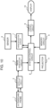
- Fig. 1 is a block diagram illustrating a configuration of an ultrasound diagnosis apparatus according to a first embodiment.
- the ultrasound diagnosis apparatus of the first embodiment includes an ultrasound probe 1, a transmitting/receiving circuit 2, an image generating circuit 3, a touch panel 4, a memory circuit 5, a sensor 6, an identification circuit 7, a system control circuit 8, a display control circuit 9, and a display 10.
- the ultrasound probe 1 transmits ultrasound waves to a subject and receives reflected waves therefrom.
- the ultrasound probe 1 outputs an echo signal based on the reflected waves from the subject to the transmitting/receiving circuit 2.
- the transmitting/receiving circuit 2 supplies an electric signal to the ultrasound probe 1 according to a control signal from the system control circuit 8 to cause it to transmit ultrasound waves that have been beamformed to a predetermined focal point (i.e., subjected to transmission beamforming). Further, the transmitting/receiving circuit 2 receives the echo signal from the ultrasound probe 1. The transmitting/receiving circuit 2 performs a delay process on the echo signal, thereby converting the analog echo signal into a received signal with phased addition. The transmitting/receiving circuit 2 outputs the received signal to the image generating circuit 3.
- the image generating circuit 3 generates an ultrasound image based on the received signal from the transmitting/receiving circuit 2. For example, the image generating circuit 3 performs band-pass filtering on the received signal. Thereafter, the image generating circuit 3 detects the envelope of the output signal, and performs a compression process on the detected data by logarithmic conversion. The image generating circuit 3 converts the received signal subjected to the compression process (ultrasound raster data) into a coordinate system for display (scan conversion), thereby generating an ultrasound image. The ultrasound image is displayed on the display 10 by the system control circuit 8 and the display control circuit 9.
- the touch panel 4 receives an operation by an operator such as a doctor or a technician, and outputs an operation instruction corresponding to the content of the operation to the system control circuit 8. For example, in a general operation state, the touch panel 4 displays soft keys and detects a touch of the operator's finger or the like. The touch panel 4 outputs an operation instruction corresponding to a soft key displayed at the touched position detected to the system control circuit 8. In another operation state, the touch panel 4 receives an operation instruction by touch typing (details will be described later).
- the memory circuit 5 is an example of the storage in the claims.
- the memory circuit 5 stores association information in which the type of a finger is associated with an operation instruction.
- Fig. 2 schematically illustrates the association information.
- the association information T1 is table information.
- the finger type Finger: finger 1 to finger 5
- the operation instruction Switch CODE: 0 ⁇ 1000, 0 ⁇ 1500, 0 ⁇ 1300, 0 ⁇ 1400, 0 ⁇ 1A00
- Specific types (thumb, index finger, ..., little finger) assigned to the finger type (each Finger) can be set and changed as appropriate by the operator or the like.
- specific operation instructions Freeze, SET, NEXT, etc. assigned to the operation instruction (each Switch CODE) can be set and changed as appropriate by the operator or the like.
- the memory circuit 5 may store the association information in a plurality of tables.
- the operator selects a desired one of the tables, and the association information of the selected table is used.
- the operator can select a desired table from a plurality of tables having different associations between the finger type and the operation instruction.
- the sensor 6 detects the shape and size of the operator's hand.
- Example of the hardware used for the sensor 6 include an optical sensor, a camera, and the like.
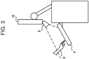
- Fig. 3 is a schematic diagram illustrating the relationship between the sensor 6 and the touch panel 4.
- the sensor 6 is appropriately installed in a position where it can detect the hand H of the operator near the touch panel 4 (the detection range of the sensor 6 is schematically indicated by a broken line).
- the sensor 6 detects the shape and size of the hand at every predetermined sampling rate, and outputs detection information indicating the shape and size detected to the identification circuit 7.
- the identification circuit 7 is a processor that identifies the type of finger having touched the touch panel 4. For example, the identification circuit 7 stores in advance statistical information in which the shape and size of the hand are associated with the finger type. The identification circuit 7 compares the detection information from the sensor 6 with the statistical information, and thereby identifies the type of each finger of the hand detected by the sensor 6. In this manner, the identification circuit 7 can identify the type of each finger located around the touch panel 4. The identification circuit 7 performs this identification process at every predetermined sampling rate.
- the system control circuit 8 is a processor that controls each part of the ultrasound diagnosis apparatus.
- the system control circuit 8 stores a program for controlling each part of the ultrasound diagnosis apparatus and executes it.
- the system control circuit 8 outputs an ultrasound image generated by the image generating circuit 3 to the display control circuit 9.
- the system control circuit 8 performs an operation instruction associated with the finger type identified by the identification circuit 7 based on the association information stored in the memory circuit 5. This operation instruction corresponds to an operation instruction provided by touch typing. Described below is the process performed in response to an operation instruction provided by touch typing.
- the touch panel 4 in the operation state for receiving touch typing need not display soft keys. Having detected a touch of the operator's finger, the touch panel 4 outputs a touched position signal indicating the touched position on the touch panel 4 to the system control circuit 8 and the identification circuit 7.
- the identification circuit 7 compares the touched position signal with the type of the finger near the touch panel 4, and thereby identifies the type of the finger that has touched the touch panel 4.
- the system control circuit 8 compares the type of the finger that has touched the touch panel 4 with the association information stored in the memory circuit 5, and thereby specifies an operation instruction associated with the type of the finger that has touched the touch panel 4.
- the system control circuit 8 uses the association information of selected one of the tables. Then, the system control circuit 8 controls each part of the ultrasound diagnosis apparatus so as to perform the operation instruction specified.
- the display control circuit 9 is a processor that displays ultrasound images and other information on the display 10.
- the display 10 is an example of the display in the claims.
- the display 10 is formed of a display device such as a liquid crystal display (LCD) or an organic electro-luminescence (EL) display.
- the display control circuit 9 displays association information on the display 10.
- Fig. 4 is a schematic diagram of association information displayed on the display 10.
- the display control circuit 9 displays association information alongside the ultrasound image.
- a schematic illustration P of the hand and texts TX1, TX2, TX3 each indicating an operation instruction associated with each finger are displayed at the lower right of the display screen D.
- the specific design for displaying the association information is not limited to such an illustration and text information, but may be set appropriately.
- the operation instruction is associated with the finger type, and the operation instruction specified by the type of the finger having touched the touch panel 4 is performed. This facilitates operator's touch typing without looking at the touch panel 4.
- an operation instruction "Freeze" is associated with the middle finger as a finger type
- the operator wishes to perform the Freeze operation during an ultrasound examination he/she can perform the Freeze operation by touching the touch panel 4 with the middle finger.
- the operation instruction of Freeze is entered.
- the operator can perform a simple operation of touching any position on the touch panel 4 with the middle finger without looking at the touch panel 4.
- the operator may touch the touch panel 4 with the finger in association with the operation instruction.
- the operation instructions set in the association information may include a switch instruction for switching on/off of the touch typing operation.
- the switch instruction is associated with the thumb as a finger type
- the operator wishes to perform touch typing he/she can turn on the touch typing operation by touching the touch panel 4 with the thumb.
- the touch typing operation can be switched on no matter where the thumb touches on the touch panel 4.
- the identification circuit 7 identifies the type of another finger that has touched the touch panel 4 with the finger associated with the switch instruction.
- the system control circuit 8 compares the type of the other finger thus identified with the association information, and thereby specifies an operation instruction associated with the type of the other finger. Then, the system control circuit 8 controls each part of the ultrasound diagnosis apparatus so as to perform the operation instruction specified.
- the display control circuit 9 displays soft keys each corresponding to an operation instruction on the touch panel 4. In this state, the touch typing operation is OFF. In this OFF state, the operator performs operation input by touching a soft key corresponding to a desired operation instruction in the same manner as the conventional soft key input.
- the operator can perform operation input on the ultrasound diagnosis apparatus while suitably switching between the touch typing operation and the conventional soft key operation.
- the operator can operate the touch panel while appropriately switching the operation input mode.
- the operability of the touch panel can be improved.
- operation instructions provided by touch typing may include the display and movement of a cursor on the display 10.
- the cursor include various cursors used by common pointing devices, measurement calipers for measuring the dimension of tissue depicted in an ultrasound image, and the like.
- the display control circuit 9 moves the position of the cursor according to the movement of the finger. Thereby, while viewing an ultrasound image displayed on the display 10, the operator can move the cursor by moving the finger touching the touch panel 4 without looking at the touch panel 4.
- an operation instruction may be associated with a combination of the two or more types of fingers.
- the display control circuit 9 moves the cursor according to the movement of these two fingers.
- the identification circuit 7 identifies the types of all fingers that are touching the touch panel 4 at the same time.
- Fig. 5 is a flowchart illustrating the operation of the ultrasound diagnosis apparatus according to the first embodiment.
- the operator performs touch typing while watching an ultrasound image during an ultrasound examination.
- Step S101 When the touch typing operation is ON, the display control circuit 9 sequentially displays ultrasound images with association information in which the finger type and the operation instruction are associated with each other on the display 10.
- Step S102 When the operator puts his/her hand close to the touch panel 4, the sensor 6 detects the shape and size of the hand of the operator. The sensor 6 outputs detection information indicating the shape and size detected to the identification circuit 7.
- Step S103 The identification circuit 7 compares the detection information from the sensor 6 with statistical information in which the shape and size of the hand are associated with the finger type, and thereby identifies the type of each finger of the hand detected by the sensor 6.
- Step S 104 The touch panel 4 outputs a touched position signal indicating the position where the finger touched to the system control circuit 8 and the identification circuit 7.
- the identification circuit 7 identifies the type of the finger that has touched the touch panel 4 by comparing the touched position signal with the type of the finger near the touch panel 4.
- Step S 105 The system control circuit 8 compares the type of the finger that has touched the touch panel 4 with the association information stored in the memory circuit 5, and thereby specifies an operation instruction associated with the type of the finger that has touched the touch panel 4. Then, the system control circuit 8 controls each part of the ultrasound diagnosis apparatus so as to perform the operation instruction specified.
- the operator can perform easy and convenient touch typing by touching any position on the touch panel 4 with a finger corresponding to a desired operation instruction without looking at the touch panel 4. Thereby, even when a flat touch panel is used, it is possible to improve the quickness and accuracy of operation input using the touch panel.
- An ultrasound diagnosis apparatus according to a first modification of the first embodiment will be described. In the following, differences from the ultrasound diagnosis apparatus of the first embodiment will be mainly described. The same description as already described in the first embodiment may not be repeated.
- the memory circuit 5 of the first modification stores association information for each partial area of the touch panel 4.
- Fig. 6 is a schematic diagram illustrating the relationship between the partial area and the association information stored in the memory circuit 5 of the first modification.
- a partial area A1 is set at the lower right of the touch panel 4 and the partial area A2 is set at the lower left of the touch panel 4.
- These partial areas (A1, A2) may be preset or may be set by operator's operation.
- association information T2 the finger type (Finger: finger 1 to finger 5) and the operation instruction (Switch CODE: 0 ⁇ 1000, 0 ⁇ 1500, 0 ⁇ 1300, 0 ⁇ 1400, 0 ⁇ 1A00) are associated with each other with respect to each of the partial areas A1 and A2.
- the system control circuit 8 specifies a partial area touched by the finger based on the touched position signal from the touch panel 4.
- the system control circuit 8 compares association information corresponding to the partial area with the type of the finger that has touched the touch panel 4 to thereby specify an operation instruction associated with the type of the finger that has touched the touch panel 4 in the association information. Then, the system control circuit 8 controls each part of the ultrasound diagnosis apparatus so as to perform the operation instruction specified.
- the association information can be set in a partial area of the touch panel where the operator can easily touch according to the positional relationship. Thereby, it is possible to improve the operability for performing operation input according to the positional relationship between the ultrasound diagnosis apparatus and the bed.
- An ultrasound diagnosis apparatus according to a second modification of the first embodiment will be described, which does not form part of the claimed subject-matter.
- differences from the ultrasound diagnosis apparatus of the first embodiment will be mainly described. The same description as already described in the first embodiment may not be repeated.
- Fig. 7 is a block diagram illustrating a configuration of a second modification.
- the identification circuit 7 of the second modification includes a specifying circuit 71.
- the specifying circuit 71 is a processor that specifies the operator based on a detection result obtained by the sensor. For example, the specifying circuit 71 stores shape and size information indicating the shape and size of the hand with respect to each operator ID. The specifying circuit 71 compares detection information from the sensor 6 with the shape and size information, and thereby specifies the operator. The specifying circuit 71 outputs the operator ID of the operator specified to the system control circuit 8.
- the memory circuit 5 stores association information with respect to each operator ID. For example, the operator can prepare association information according to the habit and preference of his/her operation and store it in the memory circuit 5 in advance.
- the system control circuit 8 performs an operation instruction based on the association information corresponding to the operator ID from the specifying circuit 71. For example, when the operator puts his/her hand close to the touch panel 4, the sensor 6 outputs detection information to the specifying circuit 71.
- the specifying circuit 71 specifies the operator based on the detection information, and outputs the operator ID of the operator specified to the system control circuit 8.
- the system control circuit 8 compares the type of the finger that has touched the touch panel 4 with the association information corresponding to the operator ID, and thereby specifies an operation instruction associated with the type of the finger that has touched the touch panel 4. Then, the system control circuit 8 controls each part of the ultrasound diagnosis apparatus so as to perform the operation instruction specified.
- association information is automatically selected according to the preference of each operator. Thereby, the operability of the touch panel for operation input can be improved according to the preference of each operator.
- Fig. 8 is a block diagram illustrating a configuration of an ultrasound diagnosis apparatus according to a third modification.
- the ultrasound diagnosis apparatus of the third modification identifies the type of the finger without using the sensor 6.
- differences from the ultrasound diagnosis apparatus of the first embodiment will be mainly described. The same description as already described in the first embodiment may not be repeated.
- the touch panel 4 detects a position touched by each of the fingers and outputs touched position information to the system control circuit 8 and the identification circuit 7. Thereby, the identification circuit 7 detects the positions of the fingers that are touching the touch panel 4.
- the identification circuit 7 identifies the type of each of the fingers based on the positional relationship of the fingers detected.
- Fig. 9 is a schematic diagram of a plurality of fingers touching the touch panel 4.
- the identification circuit 7 stores in advance statistical information on the shape of the hand.
- the statistical information includes the ratio of the lengths of the fingers and the like. With this, the relative positional relationship when each finger touches the touch panel 4 can be obtained.
- the identification circuit 7 compares the statistical information with the touched position information on the touch panel 4, and thereby individually identifies the type of each finger that has touched each touched position.
- the touched position is indicated by coordinates (finger X1 to finger X5, finger Y1 to finger Y4) with respect to each finger type identified.
- the operator can once release a finger corresponding to a desired operation instruction from the touch panel 4. At this time, the other fingers are still touching the touch panel 4. Then, the operator can enter a desired operation instruction by touching again the touch panel 4 with the finger corresponding to the desired operation instruction.
- the identification circuit 7 compares touched position information indicating a position touched by the finger that has touched again the touch panel 4 with the coordinates of the fingers identified before the finger has touched again the touch panel 4, and identifies the type of the finger that has touched again the touch panel 4. For example, in the example of Fig. 9 , when the touched position information of the finger that has touched again the touch panel 4 indicates the coordinates of "finger X3, finger Y1", the identification circuit 7 identifies the type of the finger that has touched again as "middle finger”. Incidentally, when a finger touches again the touch panel 4, the coordinates may differ from the previous coordinates. The allowable range of difference used for the identification may be appropriately set. Then, the system control circuit 8 controls each part of the ultrasound diagnosis apparatus so as to perform an operation instruction associated with the type of the finger identified.
- the operator can perform easy and convenient touch typing by touching any position on the touch panel 4 with a finger corresponding to a desired operation instruction without looking at the touch panel 4. Thereby, even when a flat touch panel is used, it is possible to improve the quickness and accuracy of operation input using the touch panel.
- Fig. 10 is a block diagram illustrating a configuration of an ultrasound diagnosis apparatus according to a fourth modification, which does not form part of the claimed subject-matter.
- the ultrasound diagnosis apparatus of the fourth modification is configured to be capable of receiving operation instructions without using a touch panel.
- differences from the first embodiment will be mainly described. The same description as already described in the first embodiment may not be repeated.
- a projector 11 projects light indicating a predetermined operation area.
- the projected light may be visible light or non-visible light.
- the light projected by the projector 11 is only required to indicate at least the outer edge of the operation area.
- a general light source, an optical modulator, a lens, and the like may be appropriately used for the hardware configuration of the projector 11.
- the sensor 6 detects the shape and size of the operator's hand in the vicinity of the operation area.
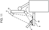
- Fig. 11 is a schematic diagram illustrating the relationship between the projector 11 and the sensor 6 and the operation area A3.
- the projector 11 projects light that indicates the operation area A3 onto a nearby flat plate or a bed.
- the function of the operation area A3 thus indicated corresponds to the function of the operation surface of the touch panel 4 in the above embodiment.
- the sensor 6 is appropriately installed in a position where it can detect the hand H of the operator in the vicinity of the operation area A3.
- the detection range of the sensor 6 is determined so as to detect the hand H located within a predetermined distance from the flat plate B and in the operation area A3. Specific numerical values of the detection range may be determined as appropriate.
- the senor 6 detects the shape and size of the hand H of the operator at each predetermined sampling rate, and outputs detection information indicating the shape and size detected to the identification circuit 7.
- the identification circuit 7 identifies a finger in the vicinity of the operation area A3 as in the above embodiment.
- operation instructions can be provided without using the touch panel 4 by projecting an operation area on a flat plate, a desk, a wall, a bed, or the like around the ultrasound diagnosis apparatus and using the operation area as the operation surface of the touch panel 4.
- the operation area as the operation surface of the touch panel 4.
- processor refers to a circuit such as, for example, a central processing unit (CPU), a graphics processing unit (GPU), an application specific integrated circuit (ASIC), a programmable logic device including a simple programmable logic device (SPLD) and a complex programmable logic device (CPLD), a field programmable gate array (FPGA), or the like.
- the processor reads programs out of a memory circuit and executes them to thereby realize the functions.
- the programs need not necessarily be stored in a memory circuit, but may be directly incorporated in the circuit of the processor. In this case, the processor realizes the functions by reading and executing the programs incorporated in the circuit.
- Each processor of the embodiments need not necessarily be configured as a single circuit.
- a plurality of independent circuits may be combined to form a single processor for implementing the functions.
- a plurality of constituent elements in Fig. 1 may be integrated into one processor to realize the functions.
- the ultrasound diagnosis apparatus of at least one embodiment described above it is possible to improve the operability of the touch panel for operation input.
Landscapes
- Engineering & Computer Science (AREA)
- Health & Medical Sciences (AREA)
- Life Sciences & Earth Sciences (AREA)
- General Engineering & Computer Science (AREA)
- Theoretical Computer Science (AREA)
- Physics & Mathematics (AREA)
- General Physics & Mathematics (AREA)
- Human Computer Interaction (AREA)
- Medical Informatics (AREA)
- Public Health (AREA)
- Biomedical Technology (AREA)
- Molecular Biology (AREA)
- Surgery (AREA)
- Animal Behavior & Ethology (AREA)
- General Health & Medical Sciences (AREA)
- Heart & Thoracic Surgery (AREA)
- Veterinary Medicine (AREA)
- Radiology & Medical Imaging (AREA)
- Biophysics (AREA)
- Pathology (AREA)
- Nuclear Medicine, Radiotherapy & Molecular Imaging (AREA)
- Multimedia (AREA)
- Ultra Sonic Daignosis Equipment (AREA)
Claims (7)
- Ultraschall-Diagnosegerät, das dazu in der Lage ist, eine Betriebsanweisung über ein Berührungsfeld zu empfangen, wobei das Gerät Folgendes umfasst:einen Speicher (5), der dafür konfiguriert ist, Verknüpfungsinformationen (T1, T2) zu speichern, in denen Betriebsanweisungen jeweils mit einer Fingerart verknüpft sind, undVerarbeitungsschaltungen, die dafür konfiguriert sind,die Fingerart eines Fingers zu identifizieren, der eine beliebige Position auf dem Berührungsfeld (4) berührt hat, undeine der Betriebsanweisungen auszuführen, die mit der auf Grundlage der Zuordnungsinformationen (T1, T2) identifizierten Fingerart verknüpft sind, wobeidie Verarbeitungsschaltungen ferner dafür konfiguriert sind,durch das Berührungsfeld Positionen einer Vielzahl von Fingern einer Hand zu erkennen, die das Berührungsfeld (4) berühren,die Fingerart jedes der Finger auf Grundlage eines Vergleichs der erkannten Positionen der Finger mit gespeicherten statistischen Informationen über die Form der Hand zu identifizieren, unddie Position eines der Finger, der von dem Berührungsfeld (4) gelöst wird und danach das Berührungsfeld (4) erneut berührt, mit den erkannten Positionen der Vielzahl von Fingern zu vergleichen, um die Fingerart des Fingers zu identifizieren,wobei die Verarbeitungsschaltungen ferner dafür konfiguriert sind, die Zuordnungsinformationen (T1, T2) auf einer Anzeige (10) anzuzeigen.
- Ultraschall-Diagnosegerät nach Anspruch 1, wobeidie Betriebsanweisungen eine Schaltanweisung zum Ein- und Ausschalten eines Berührungstippbetriebs einschließen, unddie Verarbeitungsschaltungen ferner dafür konfiguriert sind, eine der Betriebsanweisungen auszuführen, die mit der auf Grundlage der Zuordnungsinformationen (T1, T2) identifizierten Fingerart verknüpft sind, wenn der Berührungstippbetrieb eingeschaltet ist.
- Ultraschall-Diagnosegerät nach Anspruch 1, wobeiin den Zuordnungsinformationen (T1, T2) eine Schaltanweisung zum Schalten eines Steuerungszustandes der Verarbeitungsschaltungen mit einer vorbestimmten Fingerart als eine der Betriebsanweisungen verknüpft ist, unddie Verarbeitungsschaltungen ferner dafür konfiguriert sind,Fingerarten einer Vielzahl von Fingern zu identifizieren, die das Berührungsfeld (4) berührt haben, und,wenn die identifizierten Fingerarten die vorbestimmte Fingerart einschließen, eine Betriebsanweisung auszuführen, die mit einer anderen der identifizierten Fingerarten verknüpft ist.
- Ultraschall-Diagnosegerät nach Anspruch 3, wobei die Verarbeitungsschaltungen ferner dafür konfiguriert sind, Softkeys entsprechend den Betriebsanweisungen auf dem Berührungsfeld (4) anzuzeigen, wenn die identifizierten Fingerarten die vorbestimmte Fingerart nicht einschließen.
- Ultraschall-Diagnosegerät nach Anspruch 1, wobeidie Verarbeitungsschaltungen ferner dafür konfiguriert sind, einen Eingabezeiger auf einer Anzeige (10) anzuzeigen,die Betriebsanweisungen eine Bewegungsanweisung einschließen, um den Eingabezeiger zu bewegen, undwenn die identifizierte Fingerart mit der Bewegungsanweisung verknüpft ist, die Verarbeitungsschaltungen die Anzeigeposition des Eingabezeigers entsprechend einer Bewegung des Fingers bewegen.
- Ultraschall-Diagnosegerät nach Anspruch 1, wobeider Speicher (5) ferner dafür konfiguriert ist, die Zuordnungsinformationen (T1, T2) in Bezug auf jeden Teilbereich (A1, A2) des Berührungsfeldes (4) zu speichern, unddie Verarbeitungsschaltungen ferner dafür konfiguriert sind, die Fingerart eines Fingers zu identifizieren, der den Teilbereich (A1, A2) berührt hat.
- Ultraschall-Diagnosegerät nach Anspruch 1, das ferner einen Sensor (6) umfasst, der dafür konfiguriert ist, Form und Größe einer Hand eines Bedieners zu erkennen, wobeidie Verarbeitungsschaltungen ferner dafür konfiguriert sind, den Bediener auf Grundlage eines durch den Sensor (6) erhaltenen Erkennungsergebnisses zu bestimmen,der Speicher (5) ferner dafür konfiguriert ist, die Zuordnungsinformationen (T1, T2) in Bezug auf jede Bediener-ID zu speichern, unddie Verarbeitungsschaltungen ferner dafür konfiguriert sind, die Betriebsanweisungen auf Grundlage der Zuordnungsinformationen (T1, T2) auszuführen, die der Bediener-ID des bestimmten Bedieners entsprechen.
Applications Claiming Priority (2)
| Application Number | Priority Date | Filing Date | Title |
|---|---|---|---|
| JP2017010847 | 2017-01-25 | ||
| JP2017247135A JP7175605B2 (ja) | 2017-01-25 | 2017-12-25 | 超音波診断装置 |
Publications (2)
| Publication Number | Publication Date |
|---|---|
| EP3355178A1 EP3355178A1 (de) | 2018-08-01 |
| EP3355178B1 true EP3355178B1 (de) | 2023-05-24 |
Family
ID=61024692
Family Applications (1)
| Application Number | Title | Priority Date | Filing Date |
|---|---|---|---|
| EP18153290.4A Active EP3355178B1 (de) | 2017-01-25 | 2018-01-24 | Ultraschalldiagnosevorrichtung |
Country Status (2)
| Country | Link |
|---|---|
| US (1) | US20180206822A1 (de) |
| EP (1) | EP3355178B1 (de) |
Citations (2)
| Publication number | Priority date | Publication date | Assignee | Title |
|---|---|---|---|---|
| US20080163131A1 (en) * | 2005-03-28 | 2008-07-03 | Takuya Hirai | User Interface System |
| WO2013135299A1 (en) * | 2012-03-15 | 2013-09-19 | Cherradi El Fadili Ibrahim Farid | Extending the free fingers typing technology and introducing the finger taps language technology |
Family Cites Families (5)
| Publication number | Priority date | Publication date | Assignee | Title |
|---|---|---|---|---|
| JPH11296678A (ja) * | 1998-04-08 | 1999-10-29 | Nec Corp | 入力装置および入力方法 |
| US20040085300A1 (en) * | 2001-05-02 | 2004-05-06 | Alec Matusis | Device and method for selecting functions based on intrinsic finger features |
| US10667790B2 (en) * | 2012-03-26 | 2020-06-02 | Teratech Corporation | Tablet ultrasound system |
| US9075462B2 (en) * | 2012-12-10 | 2015-07-07 | Sap Se | Finger-specific input on touchscreen devices |
| KR102475820B1 (ko) * | 2015-07-07 | 2022-12-08 | 삼성메디슨 주식회사 | 의료 영상 처리 장치 및 그 동작방법 |
-
2018
- 2018-01-24 EP EP18153290.4A patent/EP3355178B1/de active Active
- 2018-01-25 US US15/879,946 patent/US20180206822A1/en not_active Abandoned
Patent Citations (2)
| Publication number | Priority date | Publication date | Assignee | Title |
|---|---|---|---|---|
| US20080163131A1 (en) * | 2005-03-28 | 2008-07-03 | Takuya Hirai | User Interface System |
| WO2013135299A1 (en) * | 2012-03-15 | 2013-09-19 | Cherradi El Fadili Ibrahim Farid | Extending the free fingers typing technology and introducing the finger taps language technology |
Also Published As
| Publication number | Publication date |
|---|---|
| EP3355178A1 (de) | 2018-08-01 |
| US20180206822A1 (en) | 2018-07-26 |
Similar Documents
| Publication | Publication Date | Title |
|---|---|---|
| US11726653B2 (en) | Non-contact gesture commands for touch screens | |
| CN102006828B (zh) | 超声波诊断装置 | |
| US10042464B2 (en) | Display apparatus including touchscreen device for detecting proximity touch and method for controlling the same | |
| EP3666193A1 (de) | Ultraschallbildgebungsvorrichtung, verfahren zur steuerung davon und computerprogrammprodukt | |
| US10201330B2 (en) | Graphical virtual controls of an ultrasound imaging system | |
| US8827909B2 (en) | Ultrasound probe | |
| CN111904462B (zh) | 用于呈现功能数据的方法和系统 | |
| US9082270B2 (en) | Haptic device with multitouch display | |
| JPH1069346A (ja) | 座標入力装置およびその制御方法 | |
| TW201602841A (zh) | 用於外部顯示器操作的可切換輸入模式 | |
| US20200088872A1 (en) | Ultrasonic detection method, ultrasonic detection system, and related apparatus | |
| JP2009080708A (ja) | 情報表示装置 | |
| US11801038B2 (en) | Ultrasound imaging system touch panel with multiple different clusters of controls | |
| CN109069104B (zh) | 超声医学检测设备及成像控制方法、成像系统、控制器 | |
| EP3355178B1 (de) | Ultraschalldiagnosevorrichtung | |
| JP2011134258A (ja) | 入力装置及びその入力装置を備えた入力制御装置 | |
| JP2010142399A (ja) | 超音波診断装置 | |
| JPH0511913A (ja) | 表示装置用キーボード | |
| JP7175605B2 (ja) | 超音波診断装置 | |
| JP2010279453A (ja) | 医療用電子機器および医療用電子機器の制御方法 | |
| JP6106243B1 (ja) | 超音波診断装置 | |
| KR102254091B1 (ko) | 터치스크린 장치 및 그 제어방법 그리고 디스플레이 장치 | |
| JP7240766B1 (ja) | 非接触入力装置 | |
| KR101005797B1 (ko) | 초음파 진단 장치의 제어 패널 | |
| US20250186023A1 (en) | Electronic device, medical instrument, and ultrasonic diagnostic apparatus |
Legal Events
| Date | Code | Title | Description |
|---|---|---|---|
| PUAI | Public reference made under article 153(3) epc to a published international application that has entered the european phase |
Free format text: ORIGINAL CODE: 0009012 |
|
| STAA | Information on the status of an ep patent application or granted ep patent |
Free format text: STATUS: REQUEST FOR EXAMINATION WAS MADE |
|
| 17P | Request for examination filed |
Effective date: 20180124 |
|
| AK | Designated contracting states |
Kind code of ref document: A1 Designated state(s): AL AT BE BG CH CY CZ DE DK EE ES FI FR GB GR HR HU IE IS IT LI LT LU LV MC MK MT NL NO PL PT RO RS SE SI SK SM TR |
|
| AX | Request for extension of the european patent |
Extension state: BA ME |
|
| STAA | Information on the status of an ep patent application or granted ep patent |
Free format text: STATUS: EXAMINATION IS IN PROGRESS |
|
| 17Q | First examination report despatched |
Effective date: 20190219 |
|
| GRAP | Despatch of communication of intention to grant a patent |
Free format text: ORIGINAL CODE: EPIDOSNIGR1 |
|
| STAA | Information on the status of an ep patent application or granted ep patent |
Free format text: STATUS: GRANT OF PATENT IS INTENDED |
|
| INTG | Intention to grant announced |
Effective date: 20221202 |
|
| GRAS | Grant fee paid |
Free format text: ORIGINAL CODE: EPIDOSNIGR3 |
|
| GRAA | (expected) grant |
Free format text: ORIGINAL CODE: 0009210 |
|
| STAA | Information on the status of an ep patent application or granted ep patent |
Free format text: STATUS: THE PATENT HAS BEEN GRANTED |
|
| AK | Designated contracting states |
Kind code of ref document: B1 Designated state(s): AL AT BE BG CH CY CZ DE DK EE ES FI FR GB GR HR HU IE IS IT LI LT LU LV MC MK MT NL NO PL PT RO RS SE SI SK SM TR |
|
| REG | Reference to a national code |
Ref country code: GB Ref legal event code: FG4D |
|
| REG | Reference to a national code |
Ref country code: CH Ref legal event code: EP |
|
| REG | Reference to a national code |
Ref country code: DE Ref legal event code: R096 Ref document number: 602018050086 Country of ref document: DE |
|
| REG | Reference to a national code |
Ref country code: AT Ref legal event code: REF Ref document number: 1569939 Country of ref document: AT Kind code of ref document: T Effective date: 20230615 |
|
| REG | Reference to a national code |
Ref country code: IE Ref legal event code: FG4D |
|
| P01 | Opt-out of the competence of the unified patent court (upc) registered |
Effective date: 20230607 |
|
| REG | Reference to a national code |
Ref country code: LT Ref legal event code: MG9D |
|
| REG | Reference to a national code |
Ref country code: NL Ref legal event code: MP Effective date: 20230524 |
|
| REG | Reference to a national code |
Ref country code: AT Ref legal event code: MK05 Ref document number: 1569939 Country of ref document: AT Kind code of ref document: T Effective date: 20230524 |
|
| PG25 | Lapsed in a contracting state [announced via postgrant information from national office to epo] |
Ref country code: SE Free format text: LAPSE BECAUSE OF FAILURE TO SUBMIT A TRANSLATION OF THE DESCRIPTION OR TO PAY THE FEE WITHIN THE PRESCRIBED TIME-LIMIT Effective date: 20230524 Ref country code: PT Free format text: LAPSE BECAUSE OF FAILURE TO SUBMIT A TRANSLATION OF THE DESCRIPTION OR TO PAY THE FEE WITHIN THE PRESCRIBED TIME-LIMIT Effective date: 20230925 Ref country code: NO Free format text: LAPSE BECAUSE OF FAILURE TO SUBMIT A TRANSLATION OF THE DESCRIPTION OR TO PAY THE FEE WITHIN THE PRESCRIBED TIME-LIMIT Effective date: 20230824 Ref country code: NL Free format text: LAPSE BECAUSE OF FAILURE TO SUBMIT A TRANSLATION OF THE DESCRIPTION OR TO PAY THE FEE WITHIN THE PRESCRIBED TIME-LIMIT Effective date: 20230524 Ref country code: ES Free format text: LAPSE BECAUSE OF FAILURE TO SUBMIT A TRANSLATION OF THE DESCRIPTION OR TO PAY THE FEE WITHIN THE PRESCRIBED TIME-LIMIT Effective date: 20230524 Ref country code: AT Free format text: LAPSE BECAUSE OF FAILURE TO SUBMIT A TRANSLATION OF THE DESCRIPTION OR TO PAY THE FEE WITHIN THE PRESCRIBED TIME-LIMIT Effective date: 20230524 |
|
| PG25 | Lapsed in a contracting state [announced via postgrant information from national office to epo] |
Ref country code: RS Free format text: LAPSE BECAUSE OF FAILURE TO SUBMIT A TRANSLATION OF THE DESCRIPTION OR TO PAY THE FEE WITHIN THE PRESCRIBED TIME-LIMIT Effective date: 20230524 Ref country code: PL Free format text: LAPSE BECAUSE OF FAILURE TO SUBMIT A TRANSLATION OF THE DESCRIPTION OR TO PAY THE FEE WITHIN THE PRESCRIBED TIME-LIMIT Effective date: 20230524 Ref country code: LV Free format text: LAPSE BECAUSE OF FAILURE TO SUBMIT A TRANSLATION OF THE DESCRIPTION OR TO PAY THE FEE WITHIN THE PRESCRIBED TIME-LIMIT Effective date: 20230524 Ref country code: LT Free format text: LAPSE BECAUSE OF FAILURE TO SUBMIT A TRANSLATION OF THE DESCRIPTION OR TO PAY THE FEE WITHIN THE PRESCRIBED TIME-LIMIT Effective date: 20230524 Ref country code: IS Free format text: LAPSE BECAUSE OF FAILURE TO SUBMIT A TRANSLATION OF THE DESCRIPTION OR TO PAY THE FEE WITHIN THE PRESCRIBED TIME-LIMIT Effective date: 20230924 Ref country code: HR Free format text: LAPSE BECAUSE OF FAILURE TO SUBMIT A TRANSLATION OF THE DESCRIPTION OR TO PAY THE FEE WITHIN THE PRESCRIBED TIME-LIMIT Effective date: 20230524 Ref country code: GR Free format text: LAPSE BECAUSE OF FAILURE TO SUBMIT A TRANSLATION OF THE DESCRIPTION OR TO PAY THE FEE WITHIN THE PRESCRIBED TIME-LIMIT Effective date: 20230825 |
|
| PG25 | Lapsed in a contracting state [announced via postgrant information from national office to epo] |
Ref country code: FI Free format text: LAPSE BECAUSE OF FAILURE TO SUBMIT A TRANSLATION OF THE DESCRIPTION OR TO PAY THE FEE WITHIN THE PRESCRIBED TIME-LIMIT Effective date: 20230524 |
|
| PG25 | Lapsed in a contracting state [announced via postgrant information from national office to epo] |
Ref country code: SK Free format text: LAPSE BECAUSE OF FAILURE TO SUBMIT A TRANSLATION OF THE DESCRIPTION OR TO PAY THE FEE WITHIN THE PRESCRIBED TIME-LIMIT Effective date: 20230524 |
|
| PG25 | Lapsed in a contracting state [announced via postgrant information from national office to epo] |
Ref country code: SM Free format text: LAPSE BECAUSE OF FAILURE TO SUBMIT A TRANSLATION OF THE DESCRIPTION OR TO PAY THE FEE WITHIN THE PRESCRIBED TIME-LIMIT Effective date: 20230524 Ref country code: SK Free format text: LAPSE BECAUSE OF FAILURE TO SUBMIT A TRANSLATION OF THE DESCRIPTION OR TO PAY THE FEE WITHIN THE PRESCRIBED TIME-LIMIT Effective date: 20230524 Ref country code: RO Free format text: LAPSE BECAUSE OF FAILURE TO SUBMIT A TRANSLATION OF THE DESCRIPTION OR TO PAY THE FEE WITHIN THE PRESCRIBED TIME-LIMIT Effective date: 20230524 Ref country code: EE Free format text: LAPSE BECAUSE OF FAILURE TO SUBMIT A TRANSLATION OF THE DESCRIPTION OR TO PAY THE FEE WITHIN THE PRESCRIBED TIME-LIMIT Effective date: 20230524 Ref country code: DK Free format text: LAPSE BECAUSE OF FAILURE TO SUBMIT A TRANSLATION OF THE DESCRIPTION OR TO PAY THE FEE WITHIN THE PRESCRIBED TIME-LIMIT Effective date: 20230524 Ref country code: CZ Free format text: LAPSE BECAUSE OF FAILURE TO SUBMIT A TRANSLATION OF THE DESCRIPTION OR TO PAY THE FEE WITHIN THE PRESCRIBED TIME-LIMIT Effective date: 20230524 |
|
| REG | Reference to a national code |
Ref country code: DE Ref legal event code: R097 Ref document number: 602018050086 Country of ref document: DE |
|
| PLBE | No opposition filed within time limit |
Free format text: ORIGINAL CODE: 0009261 |
|
| STAA | Information on the status of an ep patent application or granted ep patent |
Free format text: STATUS: NO OPPOSITION FILED WITHIN TIME LIMIT |
|
| 26N | No opposition filed |
Effective date: 20240227 |
|
| PG25 | Lapsed in a contracting state [announced via postgrant information from national office to epo] |
Ref country code: SI Free format text: LAPSE BECAUSE OF FAILURE TO SUBMIT A TRANSLATION OF THE DESCRIPTION OR TO PAY THE FEE WITHIN THE PRESCRIBED TIME-LIMIT Effective date: 20230524 |
|
| PG25 | Lapsed in a contracting state [announced via postgrant information from national office to epo] |
Ref country code: SI Free format text: LAPSE BECAUSE OF FAILURE TO SUBMIT A TRANSLATION OF THE DESCRIPTION OR TO PAY THE FEE WITHIN THE PRESCRIBED TIME-LIMIT Effective date: 20230524 Ref country code: IT Free format text: LAPSE BECAUSE OF FAILURE TO SUBMIT A TRANSLATION OF THE DESCRIPTION OR TO PAY THE FEE WITHIN THE PRESCRIBED TIME-LIMIT Effective date: 20230524 |
|
| PG25 | Lapsed in a contracting state [announced via postgrant information from national office to epo] |
Ref country code: MC Free format text: LAPSE BECAUSE OF FAILURE TO SUBMIT A TRANSLATION OF THE DESCRIPTION OR TO PAY THE FEE WITHIN THE PRESCRIBED TIME-LIMIT Effective date: 20230524 |
|
| PG25 | Lapsed in a contracting state [announced via postgrant information from national office to epo] |
Ref country code: MC Free format text: LAPSE BECAUSE OF FAILURE TO SUBMIT A TRANSLATION OF THE DESCRIPTION OR TO PAY THE FEE WITHIN THE PRESCRIBED TIME-LIMIT Effective date: 20230524 |
|
| REG | Reference to a national code |
Ref country code: CH Ref legal event code: PL |
|
| PG25 | Lapsed in a contracting state [announced via postgrant information from national office to epo] |
Ref country code: LU Free format text: LAPSE BECAUSE OF NON-PAYMENT OF DUE FEES Effective date: 20240124 |
|
| GBPC | Gb: european patent ceased through non-payment of renewal fee |
Effective date: 20240124 |
|
| PG25 | Lapsed in a contracting state [announced via postgrant information from national office to epo] |
Ref country code: LU Free format text: LAPSE BECAUSE OF NON-PAYMENT OF DUE FEES Effective date: 20240124 |
|
| PG25 | Lapsed in a contracting state [announced via postgrant information from national office to epo] |
Ref country code: GB Free format text: LAPSE BECAUSE OF NON-PAYMENT OF DUE FEES Effective date: 20240124 |
|
| PG25 | Lapsed in a contracting state [announced via postgrant information from national office to epo] |
Ref country code: BE Free format text: LAPSE BECAUSE OF NON-PAYMENT OF DUE FEES Effective date: 20240131 |
|
| PG25 | Lapsed in a contracting state [announced via postgrant information from national office to epo] |
Ref country code: FR Free format text: LAPSE BECAUSE OF NON-PAYMENT OF DUE FEES Effective date: 20240131 |
|
| PG25 | Lapsed in a contracting state [announced via postgrant information from national office to epo] |
Ref country code: CH Free format text: LAPSE BECAUSE OF NON-PAYMENT OF DUE FEES Effective date: 20240131 |
|
| PG25 | Lapsed in a contracting state [announced via postgrant information from national office to epo] |
Ref country code: GB Free format text: LAPSE BECAUSE OF NON-PAYMENT OF DUE FEES Effective date: 20240124 Ref country code: FR Free format text: LAPSE BECAUSE OF NON-PAYMENT OF DUE FEES Effective date: 20240131 Ref country code: CH Free format text: LAPSE BECAUSE OF NON-PAYMENT OF DUE FEES Effective date: 20240131 Ref country code: BE Free format text: LAPSE BECAUSE OF NON-PAYMENT OF DUE FEES Effective date: 20240131 |
|
| REG | Reference to a national code |
Ref country code: BE Ref legal event code: MM Effective date: 20240131 |
|
| PG25 | Lapsed in a contracting state [announced via postgrant information from national office to epo] |
Ref country code: BG Free format text: LAPSE BECAUSE OF FAILURE TO SUBMIT A TRANSLATION OF THE DESCRIPTION OR TO PAY THE FEE WITHIN THE PRESCRIBED TIME-LIMIT Effective date: 20230524 |
|
| PG25 | Lapsed in a contracting state [announced via postgrant information from national office to epo] |
Ref country code: BG Free format text: LAPSE BECAUSE OF FAILURE TO SUBMIT A TRANSLATION OF THE DESCRIPTION OR TO PAY THE FEE WITHIN THE PRESCRIBED TIME-LIMIT Effective date: 20230524 |
|
| PG25 | Lapsed in a contracting state [announced via postgrant information from national office to epo] |
Ref country code: IE Free format text: LAPSE BECAUSE OF NON-PAYMENT OF DUE FEES Effective date: 20240124 |
|
| PG25 | Lapsed in a contracting state [announced via postgrant information from national office to epo] |
Ref country code: IE Free format text: LAPSE BECAUSE OF NON-PAYMENT OF DUE FEES Effective date: 20240124 |
|
| PG25 | Lapsed in a contracting state [announced via postgrant information from national office to epo] |
Ref country code: CY Free format text: LAPSE BECAUSE OF FAILURE TO SUBMIT A TRANSLATION OF THE DESCRIPTION OR TO PAY THE FEE WITHIN THE PRESCRIBED TIME-LIMIT; INVALID AB INITIO Effective date: 20180124 |
|
| PG25 | Lapsed in a contracting state [announced via postgrant information from national office to epo] |
Ref country code: HU Free format text: LAPSE BECAUSE OF FAILURE TO SUBMIT A TRANSLATION OF THE DESCRIPTION OR TO PAY THE FEE WITHIN THE PRESCRIBED TIME-LIMIT; INVALID AB INITIO Effective date: 20180124 |
|
| PG25 | Lapsed in a contracting state [announced via postgrant information from national office to epo] |
Ref country code: TR Free format text: LAPSE BECAUSE OF FAILURE TO SUBMIT A TRANSLATION OF THE DESCRIPTION OR TO PAY THE FEE WITHIN THE PRESCRIBED TIME-LIMIT Effective date: 20230524 |
|
| PGFP | Annual fee paid to national office [announced via postgrant information from national office to epo] |
Ref country code: DE Payment date: 20251203 Year of fee payment: 9 |