EP3355425A1 - Assemblage d'une boîte d'installation et matériel d'installation électrique, boîte d'installation et insert étanche à l'air - Google Patents
Assemblage d'une boîte d'installation et matériel d'installation électrique, boîte d'installation et insert étanche à l'air Download PDFInfo
- Publication number
- EP3355425A1 EP3355425A1 EP17153932.3A EP17153932A EP3355425A1 EP 3355425 A1 EP3355425 A1 EP 3355425A1 EP 17153932 A EP17153932 A EP 17153932A EP 3355425 A1 EP3355425 A1 EP 3355425A1
- Authority
- EP
- European Patent Office
- Prior art keywords
- airtight
- installation
- circumferential wall
- insert
- installation box
- Prior art date
- Legal status (The legal status is an assumption and is not a legal conclusion. Google has not performed a legal analysis and makes no representation as to the accuracy of the status listed.)
- Granted
Links
Images




Classifications
-
- H—ELECTRICITY
- H02—GENERATION; CONVERSION OR DISTRIBUTION OF ELECTRIC POWER
- H02G—INSTALLATION OF ELECTRIC CABLES OR LINES, OR OF COMBINED OPTICAL AND ELECTRIC CABLES OR LINES
- H02G3/00—Installations of electric cables or lines or protective tubing therefor in or on buildings, equivalent structures or vehicles
- H02G3/02—Details
- H02G3/08—Distribution boxes; Connection or junction boxes
- H02G3/086—Assembled boxes
-
- H—ELECTRICITY
- H02—GENERATION; CONVERSION OR DISTRIBUTION OF ELECTRIC POWER
- H02G—INSTALLATION OF ELECTRIC CABLES OR LINES, OR OF COMBINED OPTICAL AND ELECTRIC CABLES OR LINES
- H02G3/00—Installations of electric cables or lines or protective tubing therefor in or on buildings, equivalent structures or vehicles
- H02G3/02—Details
- H02G3/08—Distribution boxes; Connection or junction boxes
- H02G3/088—Dustproof, splashproof, drip-proof, waterproof, or flameproof casings or inlets
-
- H—ELECTRICITY
- H02—GENERATION; CONVERSION OR DISTRIBUTION OF ELECTRIC POWER
- H02G—INSTALLATION OF ELECTRIC CABLES OR LINES, OR OF COMBINED OPTICAL AND ELECTRIC CABLES OR LINES
- H02G3/00—Installations of electric cables or lines or protective tubing therefor in or on buildings, equivalent structures or vehicles
- H02G3/02—Details
- H02G3/08—Distribution boxes; Connection or junction boxes
- H02G3/12—Distribution boxes; Connection or junction boxes for flush mounting
-
- H—ELECTRICITY
- H02—GENERATION; CONVERSION OR DISTRIBUTION OF ELECTRIC POWER
- H02G—INSTALLATION OF ELECTRIC CABLES OR LINES, OR OF COMBINED OPTICAL AND ELECTRIC CABLES OR LINES
- H02G3/00—Installations of electric cables or lines or protective tubing therefor in or on buildings, equivalent structures or vehicles
- H02G3/02—Details
- H02G3/08—Distribution boxes; Connection or junction boxes
- H02G3/081—Bases, casings or covers
- H02G3/083—Inlets
- H02G3/085—Inlets including knock-out or tear-out sections
Definitions
- the invention relates to an assembly of an installation box and electric installation material with electric wirings, the installation box comprising a housing with a first bottom wall and a first circumferential wall upright from the first bottom wall, wherein the first bottom wall and the first circumferential wall together confine an installation space for electric installation material, wherein an upper edge of the first circumferential wall facing away from the first bottom wall confines an installation opening for providing access to the installation space, wherein the first circumferential wall is provided with a passage for electric wirings to pass through the first circumferential wall.
- the invention further relates to an installation box and an airtight insert.
- Such installation boxes are applied in electric installations in utility constructions, whereby the installations boxes are installed in a hollow wall.
- the ends of electric cables or wires of the electric installations are inserted through the passage in the first circumferential wall into the installation boxes to be connected to further installation material, for example a socket or a light switch, which is installed onto a front plate of the hollow wall.
- a disadvantage of the known installation boxes is that due to the passage in the first circumferential wall and the installation opening being in direct communication with each other, therewith forming a flow channel through the installation box via which a draught occurs by air flowing freely through the installation opening, the passage in the first circumferential wall and subsequently into the hollow wall, or vice versa.
- Such draught gives people near or around the installation boxes the impression that a cold wind flow is present from or towards the installation box.
- Such cold wind flow reduces the comfort of the utility construction and the energy efficiency of the utility construction.
- dust and dirt can be transported from the inside of the wall to the front surface of the wall resulting in a dirty surface around the socket or switch.
- the invention provides an assembly of an installation box and electric installation material with electric wirings
- the installation box comprises a housing with a first bottom wall and a first circumferential wall upright from the first bottom wall, wherein the first bottom wall and the first circumferential wall together enclose an installation space for electric installation material, wherein an upper edge of the first circumferential wall facing away from the first bottom wall confines an installation opening for providing access to the installation space, wherein the first circumferential wall is provided with a passage for electric wirings to pass through the first circumferential wall
- the installation box further comprises a separate airtight insert in the installation space, wherein the airtight insert comprises a second bottom wall and a second circumferential wall upright from the second bottom wall and an upper edge facing away from the second bottom wall, wherein the outer side of the second bottom wall and the second circumferential wall are beyond the installation opening and the passage complementary to the inner side of the first bottom wall and the first circumferential wall.
- the airtight insert is placed inside the installation space and therewith between the passage in the first circumferential wall and the installation opening, the flow channel through the installation box is blocked. Thus, air may be prevented from flowing through the installation opening, the passage and subsequently into a hollow wall, or vice versa.
- the installation opening has thus a positive contribution to the comfort of the utility construction and an improved installation box is therewith provided.
- the outside of the airtight insert and the inside of the housing of the installation box beyond the installation opening and the passage are complementary to each other, a tight fitting of the airtight insert within the housing of the installation box may be accomplished. Additionally, due to the tight fitting of the airtight insert, the volume of the installation space available for installing electric installation material may be used to the utmost.
- the airtight insert comprises an inner layer and an outer layer, wherein one of the inner layer and the outer layer is manufactured from a rigid material, such as polyolefin, preferably polypropylene, and wherein the other one is manufactured from an elastic material, such as a thermoplastic elastomer.
- the inner layer is manufactured from the rigid material and the outer layer is manufactured from the elastic material.
- the rigid layer may contribute to maintaining the shape of the airtight insert during use thereof, such that the installation space remains useable optimally.
- the layer of elastic material may contribute to the airtightness of the airtight insert. Due to the elastic material it is relatively simple to accomplish airtightness for example by tightly enclosing the wires of the electric wirings by the elastic material. It is further advantageous that the airtight insert may be handled as a single unit.
- the airtight insert comprises an airtight flange provided at or near the upper edge of the second circumferential wall.
- the airtight insert is part of the outer layer of the airtight insert.
- the airtight flange extends in a direction substantially parallel or parallel to the second bottom wall and over and beyond the upper edge of the first circumferential wall, wherein the airtight flange is configured to abut at least a part of the installation material. Due to the airtight flange and the elastic material thereof, an opening between a mounting plate of the installation material installed to the front plate of the hollow wall and the front plate itself is closed by the airtight flange, in particular by the mounting plate abutting against the airtight flange. Therefore the possible flow channel through the installation box may be closed at both ends thereof and/or air is prevented from flowing along the outside of the housing of the installation box towards or away from the front plate of the hollow wall.
- the installation box is provided with two or more first flanges that form one unity with and project from the first circumferential wall in a direction parallel to the first bottom wall, and wherein the airtight flange comprises two or more receiving recesses at a side of the airtight flange facing the first and/or second bottom wall, wherein each of the receiving recesses is adapted for receiving one of the two or more first flanges.
- the installation box comprises two or more opposite mounting plates adjacent to the upper edge of the first circumferential wall, in which mounting screws for the installation material are received, wherein the airtight insert comprises two or more opposite securing plates adjacent to the upper edge of the second circumferential wall, which securing plates are placed onto the mounting plates and through which the mounting screws pass.
- the airtight insert may therefore be installed concurrently with the installation box and shall be clamped between the housing of the installation box and the installation material, in particular the mounting plate of the installation material. The airtight insert is thus easily installable together with the installation box without the need for additional operations or tools.
- the securing plates are part of the inner layer of the airtight insert, i.e. the rigid inner layer of the airtight insert.
- the securing plates are capable of withstanding forces applied to the securing plates via for example the mounting plate of the installation material, therewith establishing a reliable securing of the airtight insert to the housing of the installation box.
- the outer layer of the airtight insert i.e. the elastic outer layer
- the elastic outer layer comprises securing openings for receiving the securing plates.
- the first circumferential wall is provided with at least one pair of slide couplings, such that the installation box is coupleable (or linkable) with a further installation box, wherein the first circumferential wall is provided with a passage below each of the at least one pair of slide couplings, and the second circumferential wall is provided with at least one first membrane adjacent to the passage below the at least one pair of slide couplings.
- the first membrane will abut the electric wire in a clamping manner over a few millimetres in length, like a cuff, such that an airtight seal is provided. Due to the airtight seal, the chance of a draught occurring along the wire is reduced or in an ideal situation eliminated.
- the at least one first membrane is provided by the outer layer of the airtight insert, i.e. the elastic layer in particular manufactured from a thermoplastic elastomer, and the first membrane is framed by an aperture in the inner layer of the airtight insert, i.e. the rigid layer. Due to the aperture being provided in the thermoplastic elastomer, it is relatively simple to puncture the first membrane in the outer layer with an end of an electrical wire by forcing the end of the electric wire through the outer layer. The framing of the first membrane(s) by means of the aperture in the rigid inner layer keeps the outer layer substantially in place during puncturing of the first membrane(s) in the outer layer in a direction from the outer layer towards the inner layer.
- the airtight insert comprises two or more sub-flanges at or near the upper edge of the second circumferential wall.
- the airtight flange is provided with two or more flange openings for receiving the two or more sub-flanges.
- the sub-flanges are part of the inner layer of the airtight insert. The sub-flanges preferably extend at least partially into the airtight flange, therewith improving the stability of the airtight flange such that the intended orientation of the airtight flange may be maintained.
- the second circumferential wall has a second membrane with one or more target fractures that may be closed off by a membrane, through which the electric wirings can pass, wherein the electric wirings passing through the one or more target fractures are enclosed in an airtight manner, wherein the number of target fractures optionally corresponds to the number of wires of the electric wirings.
- the second membrane with the one or more target fractures is provided in the outer layer of the airtight insert, and wherein the second membrane with the one or more target fractures is framed by at least one aperture provided in the inner layer of the airtight insert.
- the membrane of the target fracture When an electric wire punctures the membrane of the target fracture, the membrane will abut the electric wire in a clamping manner over a few millimetres in length, like a cuff, such that an airtight seal is provided. Due to the airtight seal, the chance of a draught occurring along the wire is reduced or in an ideal situation eliminated.
- the aperture being provided in the elastic outer layer, it may be relatively simple to puncture the outer layer with an end of an electrical wire by forcing the end of the electric wire through the outer layer.
- the framing of the second membrane with the one or more target fractures by means of the aperture in the rigid inner layer may keep the outer layer substantially in place during puncturing of the outer layer in a direction from the outer layer towards the inner layer.
- each wire opening encloses the electric wire in an airtight manner
- the risk of air flowing through the wire openings between the airtight insert and the electric wires may be further reduced or eliminated.
- the airtight insert is manufactured by means of injection moulding, preferably 2k injection moulding, wherein one component used is polypropylene and another component used is a thermoplastic elastomer.
- the invention provides an installation box for use in an assembly according to the first aspect of the invention.
- the installation box according to the second aspect of the invention has at least the advantages which are described in relation to the first aspect of the invention.
- the invention provides an airtight insert for use in an assembly according to the first aspect of the invention or the installation box according to the second aspect of the invention.
- the invention provides computer-readable medium having computer-executable instructions adapted to cause a 3D printer to print an installation box according to the second aspect of the invention or an airtight insert according to the third aspect of the invention.
- FIG. 1 shows an installation box 10 in which an airtight insert 50 can be inserted according to an embodiment of the invention.
- the installation box 10 comprises a first bottom wall 11 and a first straight cylindrical circumferential wall 12 with central axis S.
- the upper edge 14 of the first circumferential wall 12 bounds an installation opening of the installation box 10.
- the first bottom wall 11 and the first circumferential wall 12 together confine an installation space, are made of plastic, in this example polypropylene, and form one rigid unity.
- the installation box 10 comprises two opposite mounting plates 16 adjacent to the upper edge 14 in which mounting screws 18 are screwed.
- the mounting screws 18 extend through recessed channels 17 behind the mounting plates 16.
- slide couplings 19 on the first circumferential wall 12 to couple multiple installation boxes 10 adjacent to each other in different configurations.
- the first circumferential wall 12 is provided with square passages 20 that are closed off with breakout ports 21 that are removed for electric wirings between the coupled installation boxes 10.
- the installation box 10 is provided with first flanges 22 that form one unity with and that project from the first circumferential wall 12 to engage onto the front plate 2 of the hollow wall 1.
- the installation box 10 comprises in this example one spout insert 24 having in this example two spouts 25 for coupling rigid or flexible pipes 4 of the electrical installation to the installation box 10 as schematically shown in figure 1 .
- the spout insert 24 is located symmetrically between the mounting screws 18. The spout insert 24 is inserted from the inside after the installation box 10 is placed in the hollow wall 1.
- the installation box 10 is provided with two identical anchoring strips 30 for anchoring the installation box 10 in the front plate 2 of the hollow wall 1.
- the anchoring strips 30 are located opposite to each other and in circumferential direction at 85 to 95 degrees with respect to the opposite first flanges 22 and at about 40 degrees with respect to the mounting screws 18.
- the anchoring strips 30 are made of a plastic with a high tension strength, in particular POM (Polyoxymethylene), and comprise an elongate gripping section 31 that rectilinearly continues into an elongate tensioning section 41. At the opposite end the tensioning section 41 is connected to an anchoring section 65.
- the gripping section 31 comprises a hole 35 in the middle thereof for insertion of a pulling tool, such as a screwdriver.
- the installation box 10 comprises two guide channels 73 in the first circumferential wall 12 in which the anchoring strip 30 is received.
- the anchoring strips 30 are locked by means of barbed metal inserts 80.
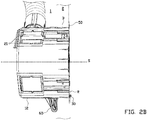
- FIGs 2A and 2B show the installation box 10 in which the airtight insert 50 is inserted into the installation space according to an embodiment of the invention.
- the installation box 10 is designed to be installed in a hollow wall 1 of a building to install the electrical installation thereof.
- the installation box 10 is inserted and secured into a circular hole 3 in the front plate 2 of the hollow wall 1.
- the anchoring strip 30 is ruptured along rupture line R when the installation box 10 with the airtight insert 50 has been installed.
- the airtight insert 50 is designed to be placed in the longitudinal direction of the central axis S inside the installation box 10 in order to prevent a draught of air through the installation opening of the installation box 10 and the spouts 25, or vice versa, and along the outside of the installation box 10.
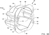
- the airtight insert 50 comprises a second bottom wall 51 and a second straight cylindrical circumferential wall 52 with central axis S.
- the upper edge 53 of the second circumferential wall 52 also bounds an installation opening, which installation opening overlaps the installation opening of the installation box 10 when the airtight insert 50 is inserted in the installation box 10.
- the outside of the second bottom wall 51 and the second circumferential wall 52 of the airtight insert 50 are beyond the installation opening and the passages 20 substantially complementary to the inside of the first bottom wall 11 and the first circumferential wall 12 of the installation box 10.
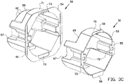
- the airtight insert 50 is manufactured by injection moulding, for example 2K injection moulding. As can be seen in figure 3C , the airtight insert 50 has an inner layer 70 and an outer layer 71. In figure 3C , the inner layer 70 and the outer layer 71 are shown as separate elements, which is only for the purpose of elucidating the construction of the airtight insert 50. In practice, the airtight insert 50 is manufactured by 2K injection moulding and the inner layer 70 and the outer layer 71 are permanently attached to each other.
- the inner layer 70 is manufactured from a rigid polyolefin, in this example polypropylene (PP), and the outer layer 71 is manufactured from a thermoplastic elastomer.
- the inner layer 70 is provided for retaining the shape of the airtight insert 50.
- the thermoplastic elastomer is elastic at room temperature which is advantageous for the airtightness of the airtight insert 50.
- the airtight insert 50 in particular the outer layer 71 thereof, comprises at the upper edge 53 an airtight flange 54 which merges into the second circumferential wall 52.
- the airtight flange 54 extends radially outwards with respect to the central axis S, such that the airtight flange 54 is extending and lying fully over and beyond the upper edge 14 of the installation box 10 to engage the front plate 2 of the hollow wall 1.
- the inner layer 70 of the airtight insert 50 comprises two opposite securing plates 55 with securing openings 72 adjacent to the upper edge 53.
- the securing plates 55 of the airtight insert 50 are placed on top of the mounting plates 16 of the installation box 10, such that the heads of the mounting screws 18 pass loosely through securing openings 72 of the securing plates 55.
- the airtight insert 50 comprises insert channels 56 behind the securing plates 55, in which the channels 17 of the installation box 10 are confined.
- Below the insert channels 56 the outer layer 71 of the second circumferential wall 52 is provided with a virginal first membrane 57 which is framed by an aperture 67 in the inner layer 70, which virginal first membrane 57 is intended to be placed adjacent to one of the square passages 20 and can be punctured by the electric wirings between coupled installation boxes 10.
- the first membrane 57 After puncturing the first membrane 57 with for example an end of an electric wire in a direction from the outer layer 71 to the inner layer 70, the first membrane 57 will constrictive inwardly abut to the electric wire like a cuff, such that the first membrane 57 abuts tightly over a few millimeters in length against the electric wire, so that an airtight seal is provided.
- the first membrane 57 may be provided with a target fracture to facilitate its puncturing.
- the airtight flange 54 has two opposite sub-flanges 58 which are part of the inner layer 70 of the airtight insert 50.
- the outer layer 71 of the airtight insert 50, in particular the airtight flange 64 is provided with flange openings 73 for receiving the sub-flanges 58, such that the sub-flanges extend into a part of the airtight flange 54.
- the airtight flange 54 has first blind receiving recesses 74 for receiving an upper part of the barbed metal inserts 80 of the installation box 10.
- the airtight flange 54 has also second blind receiving recesses 75 for receiving the first flanges 22 of the installation box 10. Due to the first and second receiving recesses 74, 75 the underside of the airtight flange 54 can abut completely against the front plate 2 of the hollow wall 1.
- aiding lines 61 are provided on top of the airtight flange 54 and thus on the outer layer 71, adjacent to each of the securing plates 55.
- the airtight flange 54 can be cut off along the aiding lines 61.
- the installation boxes 10 can be placed adjacent to each other without the airtight flanges 54 overlapping each other, therewith providing an airtight mounting of the electric installation material onto the installation boxes 10 at the front plate 2 of the hollow wall 1.
- airtight mounting has to be understood as air is prevented from flowing between the installation material and the front plate 2 of the hollow wall.
- the outer layer 71 of the airtight insert 50 has a virginal second membrane 59 framed by an aperture 69 in the inner layer 70, which second membrane 59 is complementary to the sprout insert 24.
- the second membrane 59 has target fractures 60 for passing of electric wirings from at least one of the sprouts 25, which target fractures 60 might be closed with a thinner virginal membrane when no wire passes through.
- the thinner membrane of the target fracture 60 will constrictive inwardly abut to the electric wire like a cuff, such that the membrane abuts tightly over a few millimeters in length against the electric wire, so that an airtight seal is provided.
Landscapes
- Engineering & Computer Science (AREA)
- Architecture (AREA)
- Civil Engineering (AREA)
- Structural Engineering (AREA)
- Casings For Electric Apparatus (AREA)
- Connection Or Junction Boxes (AREA)
Priority Applications (2)
| Application Number | Priority Date | Filing Date | Title |
|---|---|---|---|
| DK17153932.3T DK3355425T3 (da) | 2017-01-31 | 2017-01-31 | Samling af en installationsboks og elektrisk installationsmateriale, installationsboks og lufttæt indsats |
| EP17153932.3A EP3355425B1 (fr) | 2017-01-31 | 2017-01-31 | Assemblage d'une boîte d'installation et matériel d'installation électrique, boîte d'installation et insert étanche à l'air |
Applications Claiming Priority (1)
| Application Number | Priority Date | Filing Date | Title |
|---|---|---|---|
| EP17153932.3A EP3355425B1 (fr) | 2017-01-31 | 2017-01-31 | Assemblage d'une boîte d'installation et matériel d'installation électrique, boîte d'installation et insert étanche à l'air |
Publications (2)
| Publication Number | Publication Date |
|---|---|
| EP3355425A1 true EP3355425A1 (fr) | 2018-08-01 |
| EP3355425B1 EP3355425B1 (fr) | 2021-10-20 |
Family
ID=57960280
Family Applications (1)
| Application Number | Title | Priority Date | Filing Date |
|---|---|---|---|
| EP17153932.3A Active EP3355425B1 (fr) | 2017-01-31 | 2017-01-31 | Assemblage d'une boîte d'installation et matériel d'installation électrique, boîte d'installation et insert étanche à l'air |
Country Status (2)
| Country | Link |
|---|---|
| EP (1) | EP3355425B1 (fr) |
| DK (1) | DK3355425T3 (fr) |
Citations (6)
| Publication number | Priority date | Publication date | Assignee | Title |
|---|---|---|---|---|
| DE102008015128A1 (de) * | 2008-03-20 | 2009-10-01 | Abb Ag | Dichthülle für ein Unterputz-Installationsgerät |
| CH706106A2 (de) * | 2012-03-27 | 2013-09-30 | Kaiser Gmbh & Co Kg | Installationsdose für elektronische Anwendungen. |
| FR3000312A1 (fr) * | 2012-12-20 | 2014-06-27 | Legrand France | Boite electrique pour appareillage electrique |
| DE102013104768A1 (de) * | 2013-05-08 | 2014-11-13 | Kaiser Gmbh & Co. Kg | Installationsdose für elektrotechnische Zwecke |
| US9258919B1 (en) * | 2014-01-03 | 2016-02-09 | Elmer Rose | Firewall insert box |
| EP3059822A1 (fr) * | 2015-02-20 | 2016-08-24 | ABB Oy | Ensemble formant boîtier d'installation électrique |
-
2017
- 2017-01-31 DK DK17153932.3T patent/DK3355425T3/da active
- 2017-01-31 EP EP17153932.3A patent/EP3355425B1/fr active Active
Patent Citations (6)
| Publication number | Priority date | Publication date | Assignee | Title |
|---|---|---|---|---|
| DE102008015128A1 (de) * | 2008-03-20 | 2009-10-01 | Abb Ag | Dichthülle für ein Unterputz-Installationsgerät |
| CH706106A2 (de) * | 2012-03-27 | 2013-09-30 | Kaiser Gmbh & Co Kg | Installationsdose für elektronische Anwendungen. |
| FR3000312A1 (fr) * | 2012-12-20 | 2014-06-27 | Legrand France | Boite electrique pour appareillage electrique |
| DE102013104768A1 (de) * | 2013-05-08 | 2014-11-13 | Kaiser Gmbh & Co. Kg | Installationsdose für elektrotechnische Zwecke |
| US9258919B1 (en) * | 2014-01-03 | 2016-02-09 | Elmer Rose | Firewall insert box |
| EP3059822A1 (fr) * | 2015-02-20 | 2016-08-24 | ABB Oy | Ensemble formant boîtier d'installation électrique |
Also Published As
| Publication number | Publication date |
|---|---|
| EP3355425B1 (fr) | 2021-10-20 |
| DK3355425T3 (da) | 2021-12-20 |
Similar Documents
| Publication | Publication Date | Title |
|---|---|---|
| US10060102B2 (en) | Plumbing supply boxes | |
| US6606753B2 (en) | Waste and overflow system for a bathtub | |
| US7988104B1 (en) | Drilling riser auxiliary clamp with integral mux clamp | |
| US20070199728A1 (en) | Lead - Through Means for Cables or Pipes | |
| CA2564553A1 (fr) | Joint d'etancheite a cordon pour niches d'eclairage de piscine et de cuve thermale | |
| MX2008015618A (es) | Conector electrico con ensamble de brida de enchufe y metodos relacionados. | |
| CN102767646A (zh) | 一种电缆进线密封装置及具有该密封装置的配电箱 | |
| CN102474039A (zh) | 密封构件 | |
| PE20061405A1 (es) | Bastidor de soporte para el montaje en la pared de un aparato electrico | |
| JP2017533393A (ja) | コルゲートチューブ用の連結組立体 | |
| JP2008532837A (ja) | 空洞および排水要素を備えた航空機構造要素 | |
| ES2718224T3 (es) | Caja eléctrica estanca para encastrar en una pared | |
| EP3355425B1 (fr) | Assemblage d'une boîte d'installation et matériel d'installation électrique, boîte d'installation et insert étanche à l'air | |
| US8445778B2 (en) | Cable entry device for wiring boxes | |
| FI103915B (fi) | Kestomuovimateriaalista tehty haaraliitin putkijohtoa varten | |
| ES2285306T3 (es) | Placa de paso de cable. | |
| US20160069489A1 (en) | Hose Connection Device | |
| CN218806300U (zh) | 电池盒防水结构及独轮车 | |
| RU2422961C2 (ru) | Герметичное соединительное приспособление с гибкой диафрагмой между электромонтажным коробом и приборной коробкой | |
| IT201800009400A1 (it) | Kit per la realizzazione di impianti di diffusione di aria | |
| KR101667134B1 (ko) | 터널용 통신 케이블 고정구 | |
| JP3570805B2 (ja) | ケーブル接続用ケースにおける端面シール部材 | |
| US6427399B1 (en) | Block window system with border frame | |
| KR20100114769A (ko) | 차량용 선루프의 배수장치 | |
| US9631354B1 (en) | Urinal coupling device, assembly and installation method |
Legal Events
| Date | Code | Title | Description |
|---|---|---|---|
| PUAI | Public reference made under article 153(3) epc to a published international application that has entered the european phase |
Free format text: ORIGINAL CODE: 0009012 |
|
| STAA | Information on the status of an ep patent application or granted ep patent |
Free format text: STATUS: THE APPLICATION HAS BEEN PUBLISHED |
|
| AK | Designated contracting states |
Kind code of ref document: A1 Designated state(s): AL AT BE BG CH CY CZ DE DK EE ES FI FR GB GR HR HU IE IS IT LI LT LU LV MC MK MT NL NO PL PT RO RS SE SI SK SM TR |
|
| AX | Request for extension of the european patent |
Extension state: BA ME |
|
| STAA | Information on the status of an ep patent application or granted ep patent |
Free format text: STATUS: REQUEST FOR EXAMINATION WAS MADE |
|
| 17P | Request for examination filed |
Effective date: 20190131 |
|
| RBV | Designated contracting states (corrected) |
Designated state(s): AL AT BE BG CH CY CZ DE DK EE ES FI FR GB GR HR HU IE IS IT LI LT LU LV MC MK MT NL NO PL PT RO RS SE SI SK SM TR |
|
| STAA | Information on the status of an ep patent application or granted ep patent |
Free format text: STATUS: EXAMINATION IS IN PROGRESS |
|
| 17Q | First examination report despatched |
Effective date: 20200107 |
|
| RAP1 | Party data changed (applicant data changed or rights of an application transferred) |
Owner name: ABB SCHWEIZ AG |
|
| GRAP | Despatch of communication of intention to grant a patent |
Free format text: ORIGINAL CODE: EPIDOSNIGR1 |
|
| STAA | Information on the status of an ep patent application or granted ep patent |
Free format text: STATUS: GRANT OF PATENT IS INTENDED |
|
| RIC1 | Information provided on ipc code assigned before grant |
Ipc: H02G 3/12 20060101ALI20201016BHEP Ipc: H02G 3/08 20060101AFI20201016BHEP |
|
| INTG | Intention to grant announced |
Effective date: 20201103 |
|
| GRAJ | Information related to disapproval of communication of intention to grant by the applicant or resumption of examination proceedings by the epo deleted |
Free format text: ORIGINAL CODE: EPIDOSDIGR1 |
|
| STAA | Information on the status of an ep patent application or granted ep patent |
Free format text: STATUS: EXAMINATION IS IN PROGRESS |
|
| INTC | Intention to grant announced (deleted) | ||
| GRAP | Despatch of communication of intention to grant a patent |
Free format text: ORIGINAL CODE: EPIDOSNIGR1 |
|
| STAA | Information on the status of an ep patent application or granted ep patent |
Free format text: STATUS: GRANT OF PATENT IS INTENDED |
|
| INTG | Intention to grant announced |
Effective date: 20210503 |
|
| GRAS | Grant fee paid |
Free format text: ORIGINAL CODE: EPIDOSNIGR3 |
|
| GRAA | (expected) grant |
Free format text: ORIGINAL CODE: 0009210 |
|
| STAA | Information on the status of an ep patent application or granted ep patent |
Free format text: STATUS: THE PATENT HAS BEEN GRANTED |
|
| AK | Designated contracting states |
Kind code of ref document: B1 Designated state(s): AL AT BE BG CH CY CZ DE DK EE ES FI FR GB GR HR HU IE IS IT LI LT LU LV MC MK MT NL NO PL PT RO RS SE SI SK SM TR |
|
| REG | Reference to a national code |
Ref country code: GB Ref legal event code: FG4D |
|
| REG | Reference to a national code |
Ref country code: CH Ref legal event code: EP |
|
| REG | Reference to a national code |
Ref country code: IE Ref legal event code: FG4D |
|
| REG | Reference to a national code |
Ref country code: DE Ref legal event code: R096 Ref document number: 602017047775 Country of ref document: DE |
|
| REG | Reference to a national code |
Ref country code: AT Ref legal event code: REF Ref document number: 1440710 Country of ref document: AT Kind code of ref document: T Effective date: 20211115 |
|
| REG | Reference to a national code |
Ref country code: DK Ref legal event code: T3 Effective date: 20211213 |
|
| REG | Reference to a national code |
Ref country code: SE Ref legal event code: TRGR |
|
| REG | Reference to a national code |
Ref country code: NL Ref legal event code: FP |
|
| REG | Reference to a national code |
Ref country code: LT Ref legal event code: MG9D |
|
| REG | Reference to a national code |
Ref country code: AT Ref legal event code: MK05 Ref document number: 1440710 Country of ref document: AT Kind code of ref document: T Effective date: 20211020 |
|
| PG25 | Lapsed in a contracting state [announced via postgrant information from national office to epo] |
Ref country code: RS Free format text: LAPSE BECAUSE OF FAILURE TO SUBMIT A TRANSLATION OF THE DESCRIPTION OR TO PAY THE FEE WITHIN THE PRESCRIBED TIME-LIMIT Effective date: 20211020 Ref country code: LT Free format text: LAPSE BECAUSE OF FAILURE TO SUBMIT A TRANSLATION OF THE DESCRIPTION OR TO PAY THE FEE WITHIN THE PRESCRIBED TIME-LIMIT Effective date: 20211020 Ref country code: FI Free format text: LAPSE BECAUSE OF FAILURE TO SUBMIT A TRANSLATION OF THE DESCRIPTION OR TO PAY THE FEE WITHIN THE PRESCRIBED TIME-LIMIT Effective date: 20211020 Ref country code: BG Free format text: LAPSE BECAUSE OF FAILURE TO SUBMIT A TRANSLATION OF THE DESCRIPTION OR TO PAY THE FEE WITHIN THE PRESCRIBED TIME-LIMIT Effective date: 20220120 Ref country code: AT Free format text: LAPSE BECAUSE OF FAILURE TO SUBMIT A TRANSLATION OF THE DESCRIPTION OR TO PAY THE FEE WITHIN THE PRESCRIBED TIME-LIMIT Effective date: 20211020 |
|
| PG25 | Lapsed in a contracting state [announced via postgrant information from national office to epo] |
Ref country code: IS Free format text: LAPSE BECAUSE OF FAILURE TO SUBMIT A TRANSLATION OF THE DESCRIPTION OR TO PAY THE FEE WITHIN THE PRESCRIBED TIME-LIMIT Effective date: 20220220 Ref country code: PT Free format text: LAPSE BECAUSE OF FAILURE TO SUBMIT A TRANSLATION OF THE DESCRIPTION OR TO PAY THE FEE WITHIN THE PRESCRIBED TIME-LIMIT Effective date: 20220221 Ref country code: PL Free format text: LAPSE BECAUSE OF FAILURE TO SUBMIT A TRANSLATION OF THE DESCRIPTION OR TO PAY THE FEE WITHIN THE PRESCRIBED TIME-LIMIT Effective date: 20211020 Ref country code: NO Free format text: LAPSE BECAUSE OF FAILURE TO SUBMIT A TRANSLATION OF THE DESCRIPTION OR TO PAY THE FEE WITHIN THE PRESCRIBED TIME-LIMIT Effective date: 20220120 Ref country code: LV Free format text: LAPSE BECAUSE OF FAILURE TO SUBMIT A TRANSLATION OF THE DESCRIPTION OR TO PAY THE FEE WITHIN THE PRESCRIBED TIME-LIMIT Effective date: 20211020 Ref country code: HR Free format text: LAPSE BECAUSE OF FAILURE TO SUBMIT A TRANSLATION OF THE DESCRIPTION OR TO PAY THE FEE WITHIN THE PRESCRIBED TIME-LIMIT Effective date: 20211020 Ref country code: GR Free format text: LAPSE BECAUSE OF FAILURE TO SUBMIT A TRANSLATION OF THE DESCRIPTION OR TO PAY THE FEE WITHIN THE PRESCRIBED TIME-LIMIT Effective date: 20220121 Ref country code: ES Free format text: LAPSE BECAUSE OF FAILURE TO SUBMIT A TRANSLATION OF THE DESCRIPTION OR TO PAY THE FEE WITHIN THE PRESCRIBED TIME-LIMIT Effective date: 20211020 |
|
| REG | Reference to a national code |
Ref country code: DE Ref legal event code: R097 Ref document number: 602017047775 Country of ref document: DE |
|
| PG25 | Lapsed in a contracting state [announced via postgrant information from national office to epo] |
Ref country code: SM Free format text: LAPSE BECAUSE OF FAILURE TO SUBMIT A TRANSLATION OF THE DESCRIPTION OR TO PAY THE FEE WITHIN THE PRESCRIBED TIME-LIMIT Effective date: 20211020 Ref country code: SK Free format text: LAPSE BECAUSE OF FAILURE TO SUBMIT A TRANSLATION OF THE DESCRIPTION OR TO PAY THE FEE WITHIN THE PRESCRIBED TIME-LIMIT Effective date: 20211020 Ref country code: RO Free format text: LAPSE BECAUSE OF FAILURE TO SUBMIT A TRANSLATION OF THE DESCRIPTION OR TO PAY THE FEE WITHIN THE PRESCRIBED TIME-LIMIT Effective date: 20211020 Ref country code: EE Free format text: LAPSE BECAUSE OF FAILURE TO SUBMIT A TRANSLATION OF THE DESCRIPTION OR TO PAY THE FEE WITHIN THE PRESCRIBED TIME-LIMIT Effective date: 20211020 Ref country code: CZ Free format text: LAPSE BECAUSE OF FAILURE TO SUBMIT A TRANSLATION OF THE DESCRIPTION OR TO PAY THE FEE WITHIN THE PRESCRIBED TIME-LIMIT Effective date: 20211020 |
|
| PLBE | No opposition filed within time limit |
Free format text: ORIGINAL CODE: 0009261 |
|
| STAA | Information on the status of an ep patent application or granted ep patent |
Free format text: STATUS: NO OPPOSITION FILED WITHIN TIME LIMIT |
|
| PG25 | Lapsed in a contracting state [announced via postgrant information from national office to epo] |
Ref country code: MC Free format text: LAPSE BECAUSE OF FAILURE TO SUBMIT A TRANSLATION OF THE DESCRIPTION OR TO PAY THE FEE WITHIN THE PRESCRIBED TIME-LIMIT Effective date: 20211020 |
|
| REG | Reference to a national code |
Ref country code: CH Ref legal event code: PL |
|
| 26N | No opposition filed |
Effective date: 20220721 |
|
| GBPC | Gb: european patent ceased through non-payment of renewal fee |
Effective date: 20220131 |
|
| REG | Reference to a national code |
Ref country code: BE Ref legal event code: MM Effective date: 20220131 |
|
| PG25 | Lapsed in a contracting state [announced via postgrant information from national office to epo] |
Ref country code: LU Free format text: LAPSE BECAUSE OF NON-PAYMENT OF DUE FEES Effective date: 20220131 Ref country code: GB Free format text: LAPSE BECAUSE OF NON-PAYMENT OF DUE FEES Effective date: 20220131 Ref country code: AL Free format text: LAPSE BECAUSE OF FAILURE TO SUBMIT A TRANSLATION OF THE DESCRIPTION OR TO PAY THE FEE WITHIN THE PRESCRIBED TIME-LIMIT Effective date: 20211020 |
|
| PG25 | Lapsed in a contracting state [announced via postgrant information from national office to epo] |
Ref country code: SI Free format text: LAPSE BECAUSE OF FAILURE TO SUBMIT A TRANSLATION OF THE DESCRIPTION OR TO PAY THE FEE WITHIN THE PRESCRIBED TIME-LIMIT Effective date: 20211020 Ref country code: FR Free format text: LAPSE BECAUSE OF NON-PAYMENT OF DUE FEES Effective date: 20220131 Ref country code: BE Free format text: LAPSE BECAUSE OF NON-PAYMENT OF DUE FEES Effective date: 20220131 |
|
| PG25 | Lapsed in a contracting state [announced via postgrant information from national office to epo] |
Ref country code: LI Free format text: LAPSE BECAUSE OF NON-PAYMENT OF DUE FEES Effective date: 20220131 Ref country code: CH Free format text: LAPSE BECAUSE OF NON-PAYMENT OF DUE FEES Effective date: 20220131 |
|
| PG25 | Lapsed in a contracting state [announced via postgrant information from national office to epo] |
Ref country code: IE Free format text: LAPSE BECAUSE OF NON-PAYMENT OF DUE FEES Effective date: 20220131 |
|
| PG25 | Lapsed in a contracting state [announced via postgrant information from national office to epo] |
Ref country code: IT Free format text: LAPSE BECAUSE OF FAILURE TO SUBMIT A TRANSLATION OF THE DESCRIPTION OR TO PAY THE FEE WITHIN THE PRESCRIBED TIME-LIMIT Effective date: 20211020 |
|
| PG25 | Lapsed in a contracting state [announced via postgrant information from national office to epo] |
Ref country code: HU Free format text: LAPSE BECAUSE OF FAILURE TO SUBMIT A TRANSLATION OF THE DESCRIPTION OR TO PAY THE FEE WITHIN THE PRESCRIBED TIME-LIMIT; INVALID AB INITIO Effective date: 20170131 |
|
| PG25 | Lapsed in a contracting state [announced via postgrant information from national office to epo] |
Ref country code: MK Free format text: LAPSE BECAUSE OF FAILURE TO SUBMIT A TRANSLATION OF THE DESCRIPTION OR TO PAY THE FEE WITHIN THE PRESCRIBED TIME-LIMIT Effective date: 20211020 Ref country code: CY Free format text: LAPSE BECAUSE OF FAILURE TO SUBMIT A TRANSLATION OF THE DESCRIPTION OR TO PAY THE FEE WITHIN THE PRESCRIBED TIME-LIMIT Effective date: 20211020 |
|
| PG25 | Lapsed in a contracting state [announced via postgrant information from national office to epo] |
Ref country code: TR Free format text: LAPSE BECAUSE OF FAILURE TO SUBMIT A TRANSLATION OF THE DESCRIPTION OR TO PAY THE FEE WITHIN THE PRESCRIBED TIME-LIMIT Effective date: 20211020 |
|
| PG25 | Lapsed in a contracting state [announced via postgrant information from national office to epo] |
Ref country code: MT Free format text: LAPSE BECAUSE OF FAILURE TO SUBMIT A TRANSLATION OF THE DESCRIPTION OR TO PAY THE FEE WITHIN THE PRESCRIBED TIME-LIMIT Effective date: 20211020 |
|
| PGFP | Annual fee paid to national office [announced via postgrant information from national office to epo] |
Ref country code: NL Payment date: 20260121 Year of fee payment: 10 |
|
| PGFP | Annual fee paid to national office [announced via postgrant information from national office to epo] |
Ref country code: SE Payment date: 20260121 Year of fee payment: 10 |
|
| PGFP | Annual fee paid to national office [announced via postgrant information from national office to epo] |
Ref country code: DE Payment date: 20260121 Year of fee payment: 10 Ref country code: DK Payment date: 20260126 Year of fee payment: 10 |