EP3355426A1 - Joint isolant tubulaire et dispositif isolant - Google Patents
Joint isolant tubulaire et dispositif isolant Download PDFInfo
- Publication number
- EP3355426A1 EP3355426A1 EP17382042.4A EP17382042A EP3355426A1 EP 3355426 A1 EP3355426 A1 EP 3355426A1 EP 17382042 A EP17382042 A EP 17382042A EP 3355426 A1 EP3355426 A1 EP 3355426A1
- Authority
- EP
- European Patent Office
- Prior art keywords
- insulating
- seal
- cable
- bodies
- arrangement
- Prior art date
- Legal status (The legal status is an assumption and is not a legal conclusion. Google has not performed a legal analysis and makes no representation as to the accuracy of the status listed.)
- Withdrawn
Links
- 238000005520 cutting process Methods 0.000 claims abstract description 23
- 239000004020 conductor Substances 0.000 claims abstract description 22
- 238000003780 insertion Methods 0.000 claims abstract description 15
- 230000037431 insertion Effects 0.000 claims abstract description 15
- 239000000463 material Substances 0.000 claims abstract description 8
- 238000009413 insulation Methods 0.000 claims description 21
- 239000013536 elastomeric material Substances 0.000 claims description 4
- 230000000007 visual effect Effects 0.000 claims description 3
- 238000007789 sealing Methods 0.000 description 5
- 239000000428 dust Substances 0.000 description 4
- XLYOFNOQVPJJNP-UHFFFAOYSA-N water Substances O XLYOFNOQVPJJNP-UHFFFAOYSA-N 0.000 description 3
- 230000008878 coupling Effects 0.000 description 2
- 238000010168 coupling process Methods 0.000 description 2
- 238000005859 coupling reaction Methods 0.000 description 2
- 238000009826 distribution Methods 0.000 description 2
- 230000006978 adaptation Effects 0.000 description 1
- 230000015572 biosynthetic process Effects 0.000 description 1
- 239000003795 chemical substances by application Substances 0.000 description 1
- 230000006835 compression Effects 0.000 description 1
- 238000007906 compression Methods 0.000 description 1
- 230000007423 decrease Effects 0.000 description 1
- 230000002950 deficient Effects 0.000 description 1
- 230000001419 dependent effect Effects 0.000 description 1
- 239000013013 elastic material Substances 0.000 description 1
- 230000005684 electric field Effects 0.000 description 1
- 238000010616 electrical installation Methods 0.000 description 1
- 238000010292 electrical insulation Methods 0.000 description 1
- 238000009429 electrical wiring Methods 0.000 description 1
- 238000009434 installation Methods 0.000 description 1
- 230000005923 long-lasting effect Effects 0.000 description 1
- 238000004519 manufacturing process Methods 0.000 description 1
- 238000000034 method Methods 0.000 description 1
- -1 moisture Substances 0.000 description 1
- 238000003825 pressing Methods 0.000 description 1
- 230000000717 retained effect Effects 0.000 description 1
- 150000003839 salts Chemical class 0.000 description 1
- 239000007787 solid Substances 0.000 description 1
- 230000002195 synergetic effect Effects 0.000 description 1
Images



Classifications
-
- H—ELECTRICITY
- H02—GENERATION; CONVERSION OR DISTRIBUTION OF ELECTRIC POWER
- H02G—INSTALLATION OF ELECTRIC CABLES OR LINES, OR OF COMBINED OPTICAL AND ELECTRIC CABLES OR LINES
- H02G3/00—Installations of electric cables or lines or protective tubing therefor in or on buildings, equivalent structures or vehicles
- H02G3/02—Details
- H02G3/08—Distribution boxes; Connection or junction boxes
- H02G3/081—Bases, casings or covers
- H02G3/083—Inlets
- H02G3/085—Inlets including knock-out or tear-out sections
-
- H—ELECTRICITY
- H02—GENERATION; CONVERSION OR DISTRIBUTION OF ELECTRIC POWER
- H02G—INSTALLATION OF ELECTRIC CABLES OR LINES, OR OF COMBINED OPTICAL AND ELECTRIC CABLES OR LINES
- H02G15/00—Cable fittings
- H02G15/013—Sealing means for cable inlets
-
- H—ELECTRICITY
- H01—ELECTRIC ELEMENTS
- H01R—ELECTRICALLY-CONDUCTIVE CONNECTIONS; STRUCTURAL ASSOCIATIONS OF A PLURALITY OF MUTUALLY-INSULATED ELECTRICAL CONNECTING ELEMENTS; COUPLING DEVICES; CURRENT COLLECTORS
- H01R13/00—Details of coupling devices of the kinds covered by groups H01R12/70 or H01R24/00 - H01R33/00
- H01R13/46—Bases; Cases
- H01R13/52—Dustproof, splashproof, drip-proof, waterproof, or flameproof cases
- H01R13/5205—Sealing means between cable and housing, e.g. grommet
- H01R13/5208—Sealing means between cable and housing, e.g. grommet having at least two cable receiving openings
-
- H—ELECTRICITY
- H01—ELECTRIC ELEMENTS
- H01R—ELECTRICALLY-CONDUCTIVE CONNECTIONS; STRUCTURAL ASSOCIATIONS OF A PLURALITY OF MUTUALLY-INSULATED ELECTRICAL CONNECTING ELEMENTS; COUPLING DEVICES; CURRENT COLLECTORS
- H01R4/00—Electrically-conductive connections between two or more conductive members in direct contact, i.e. touching one another; Means for effecting or maintaining such contact; Electrically-conductive connections having two or more spaced connecting locations for conductors and using contact members penetrating insulation
- H01R4/28—Clamped connections, spring connections
- H01R4/30—Clamped connections, spring connections utilising a screw or nut clamping member
- H01R4/36—Conductive members located under tip of screw
-
- H—ELECTRICITY
- H02—GENERATION; CONVERSION OR DISTRIBUTION OF ELECTRIC POWER
- H02G—INSTALLATION OF ELECTRIC CABLES OR LINES, OR OF COMBINED OPTICAL AND ELECTRIC CABLES OR LINES
- H02G3/00—Installations of electric cables or lines or protective tubing therefor in or on buildings, equivalent structures or vehicles
- H02G3/02—Details
- H02G3/06—Joints for connecting lengths of protective tubing or channels, to each other or to casings, e.g. to distribution boxes; Ensuring electrical continuity in the joint
Definitions
- the invention is in the field of insulation of electric conductor cables against moisture and dust as happens, for example, albeit no exclusively, in underground distribution networks.
- the invention relates to a tubular insulating seal for insulating the connection end of electric conductor cables of different cross sections, said seal extending along a longitudinal direction between a first insertion end and a second exit end for said cable, by which said seal can be mounted on a receiving surface.
- the invention also relates to an insulating arrangement for insulating at least one electric conductor cable, said arrangement comprising an insulating surface with at least one passage hole for the insertion of said cable.
- insulating seals formed by a plurality of cylindrical insulating bodies, ordered from larger to smaller cable cross section, in stepped tower or pyramid fashion. These seals allow electric conductor cables of different cross sections to be insulated with a single seal. To this end, the insulating bodies of a cross section smaller than the cross section of the cable it is wanted to insulate must be cut away.
- DE 102011054294 A1 discloses a seal for mounting cables of different cross sections.
- the seal is hollow on the inside and has a plurality of cylindrical insulating bodies forming a stepped tower or pyramid.
- the cross section of the cable that may be assembled is increasing from one end to the other of the seal, in the cable insertion direction.
- the seal is a smooth cone.
- Each of the steps corresponds to a predetermined cable cross section.
- the insulating bodies for cable cross sections smaller than the cross section of the cable it is wanted to mount must be cut away.
- DE 102014114568 A1 shows a hollow seal having features similar to those of the foregoing paragraph. Nevertheless, in this case, the inner form of the cylindrical insulating bodies is substantially parallel to the outer form of each insulating body.
- a cutting portion on the outer perimeter of the lower base of each insulating body adjacent another insulating body, there is provided a cutting portion, as a wedge-like perimetric groove.
- a transitional chamfer connecting both inner profiles and coinciding with the end of the outer perimetric groove. In the portion formed between the groove and the inner chamfer, there is obtained an insulation portion for the cable once the seal has been cut.
- the insulating body having the cross section appropriate for the cross section of the cable to be mounted and the insulating bodies of smaller cross section are cut away, at the level of the wedge-like groove.
- the insulation portion which is practically a sharp edge. Therefore, an incorrect cut may damage the seal or make it useless.
- the operation of cutting the seal is complicated, since when the unrequired insulating bodies are cut away across the cutting portion, it is easy to leave flashing on the inner chamfer or for the cut not to be perpendicular to the axis of the seal. Owing to this, the seal does not correctly bear against the perimeter of the cable and the insulation provided by the seal is also unreliable.
- US 2006/148336 A1 discloses a waterproof connector for insulating different cable cross sections, wherein the diameter of the insulating portion decreases in the cable insertion direction.
- This configuration means that the connector has to be made of two different parts, since otherwise easy access may not be had to the insulating bodies to cut them.
- a further important disadvantage consists of the cut being made at the end of the connector which is hidden in the interior thereof. Thus, if for example, the cutting blade is moist, when the desired end is cut, the moisture accumulates at this point. Precisely, the point where the cut has been made remains mounted inside of the insulating arrangement.
- this type of connector requires the personnel who mounts it to be well trained, to avoid incorrect mountings which would cause the unwanted ingress of moisture at the point of connection.
- an insulating seal of the type indicated at the beginning characterized in that it comprises a plurality of insulating bodies, each of said insulating bodies comprising an insulating portion for at least one cable cross section, said insulating bodies being arranged one after the other, in order according to increasing cable cross sections in the direction from said first end to said second end, and each of said insulating portions being configured as a tube of elastically deformable material, extending internally through the corresponding insulating body, in the direction from said first end to said second end, and in that between adjacent insulating bodies there are provided cutting portions along which the insulating bodies for the insulated mounting of said cable must be separated from the insulating bodies for cable cross sections smaller than the cross section of the cable that is to be mounted in said seal.
- the concept of insulation according to the invention relates not only to insulation from water and moisture, but also to insulation against dust, dirt, salts or to electrical insulation. It should also be mentioned that the seal of the invention is preferably, but not exclusively, applicable to connections of underground networks.
- a conductor cable relates to the ensemble formed by the electrical conductor and the corresponding insulating sheath covering said conductor.
- the insulating portions having a tubular form extending internally through the insulating body as a member independent of the outer wall of the insulating body, there is avoided the formation of a sharp insulating edge, such as occurs with the seals of the state of the art. In addition, this confers elasticity on the insulating portion, thereby improving the contact and adaptation to the cable perimeter.
- the insulating portion is now a tube, such that the insulating portion can be separated from the cutting portion. In addition, this also allows the insulating portion to be extended as desired.
- the insulating portion is sufficiently long to offset these problems and to prevent this from prejudicing the insulation of the cable.
- a further important advantage of the seal of the invention consists of the ease of mounting.
- the elastically deformable inner tube of the insulating portion of the seal facilitates insertion. This portion works under tension during the insertion of the cable in the direction of the end of larger cross section.
- the insulating portions work under compression which, combined with the fact that the known seals are made from rubber, facilitates the folding back of the seal over itself and make a correct sealing of the cable in this area hard to obtain.
- the invention further includes a number of preferred features that are object of the dependent claims and the utility of which will be highlighted hereinafter in the detailed description of an embodiment of the invention.
- the insulating portion of said inner tube is cylindrical, which forces the use of cables having a cylindrical cross section and prevents incorrect mounting of the cable due to rotation of the cable about its axis.
- the intention is that the cut has absolutely no relationship with the insulating function.
- the inner tube preferably comprises a frustroconical section narrowing in the direction from said first end to said second end and connecting said cutting portion with said insulating portion.
- This embodiment affords also the synergetic effect which facilitates the insertion of the cable, since the frustroconical section assumes the function of insertion guide.
- the portion for insulation can be optimized more and adapted to the corresponding insulation needs. Thereby, if a very large insulation length is not needed, it also reduces the force required to insert the cable.
- each of said cutting portions comprises a perimetric groove or a visual indicative mark extending at least along a part of the external perimeter of each of the corresponding insulation bodies.
- the elastically deformable material is preferably an elastomeric material.
- different multiple conductor cable cross sections can be mounted in one same insulating portion. These cable cross sections will be within a range which is normally limited by the cross sections which can be mounted in the insulating bodies of the seal directly adjacent the insulating body in question.
- the flexibility of the elastomeric material also affords the advantage that a cable eccentric relative to the axis of the seal may be mounted without losing the insulating properties.
- the seal of the invention is made entirely as an integral part. Thus, unnecessary points of ingress of humidity are reduced or avoided and the water-tightness of the assembly is improved.
- the seal is rotationally symmetrical about said longitudinal axis to facilitate mounting independently of the relative positions of the cable and the seal.
- said first end is closed and must be opened prior to inserting a cable.
- the seal may also serve as a sealing plug in terminal connections.
- At least one of said insulating bodies has an identification portion configured to receive a ring identifying the cable mounted in said seal.
- the invention also addresses the problem of achieving a rapid mounting of electrical wiring directly on the installation site using the smallest possible amount of material and tools.
- the invention proposes an insulating arrangement having the features indicated at the beginning, characterized in that said at least one passage hole has receiving means for insulatedly receiving a second end of a seal according to the invention.
- the coupling arrangement is an assembly kit comprising a splicing or terminal electrical connector and one or several seals according to the invention which are supplied in a container, such as for example a bag, box or the like. Also, particularly preferably it is an electrical connector for underground networks.
- said seal has at said second end a front recess and said receiving means are a tubular projection projecting from said insulating surface, said arrangement also having retaining means, such that said recess and said tubular projection are configured to couple up with one another forming an insulating mounting through said retaining means.
- the retaining means are teeth provided on the mutual contact surface of at least one of said recess and/or said tubular projection.
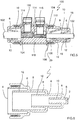
- Figures 1 and 2 show a first embodiment of a tubular insulating seal 1 for insulating the connection end of electric conductor cables 102 of different cross sections.
- Seals of this type have various applications in the electrical field, such as for example, in low and medium voltage networks, for making splicing or terminal connections. These seals 1 provide a special aid for insulating conductor cables in underground distribution networks.
- the seal 1 extends along a longitudinal direction L between a first end 2 and a second end 4.
- the cable 102 is inserted at the first end 2, while this comes out of the second end 4.
- the insulating seal 1 serves for the watertight mounting of the seal 1 on the surface where the electrical connection is made, such as for example, a cabinet, a connection box, a connector or the others.
- the seal 1 is formed from a plurality of insulating bodies 6 which in this case have a circular cross section. While the circular form is particularly appropriate for this type of insulating devices, the insulating bodies 6 could have other cross sections, such as polygonal, elliptical or others.
- the seal of Figures 1 and 2 has three insulating bodies 6 arranged in series, one after the other.
- the seal 1 is rotationally symmetrical about said longitudinal axis L.
- the insulation bodies 6 could be arranged about the longitudinal axis L, one after the other, but in such a way that an asymmetrical seal were obtained.
- the insulating bodies 6 are in an ordered fashion to receive increasing cable 102 cross sections in the direction from the first end 2 to the second end 4.
- Each of the insulating bodies 6 has an insulating portion 10 to insulatingly receive a cross section of cable 102 and, in particular, the insulating covering of the conductor cable 102.
- Each of the insulating portions 10 is a cylindrical tube of elastically deformable material extending internally through the corresponding insulating body 6 in the direction from the first end 2 to the second end 4. In addition, the tube is separated from the corresponding outer wall of the insulating body 6, which provides flexibility for facilitating the mounting and, as will be seen later hereinafter, for making eccentric mountings.
- the inner tube of elastically deformable material does not configure the entire insulating portion, but is provided furthermore with a frustroconical section 12 narrowing in the direction of insertion of the cable 102, namely, the direction from the first end 2 to the second end 4.
- This frustroconical section 12 connects the cutting portion 8 with the insulating portion 10. As will be explained in detail hereinafter, this removes the risk of damage in the insulating portion 10 when the part of the seal 1 not necessary for insulating the conductor cable 102 is cut away.
- these cutting portions 8 consist of wedge-shaped grooves, around the entire perimeter of the base of each insulating body 6.
- these cutting portions 8 could be marked by visual markings extending along a part or the entire outer perimeter of each of the corresponding insulating bodies 6.
- one or all of the insulating bodies 6 could have an identification portion 18 in which an identification ring 16 identifying the cable 102 could be mounted.
- This ring 16 may be placed, for example, on the smallest cross section insulating body, as shown, for example, in Figure 4 .
- the identification portion 18 consists of an annular recess in the perimeter of the insulating body 6. Owing to the steps formed by the recess, the ring 16 can be retained in the mounted position along the longitudinal direction L. The ring 16 may also be completely closed or have a mounting slot. Owing to the slot, the ring 16 can be opened to fit it to the corresponding identification portion 18.
- the seal 1 of Figures 1 and 2 is made as an integral part, to facilitate manufacture and subsequent mounting.
- the fact that it is an integral part also avoids the appearance of not absolutely necessary points through which moisture and water could enter. Consequently, the insulating capacity of the seal 1 is even more enhanced, since the only two areas where the moisture could potentially enter are the first and second ends 2 and 4. Nevertheless, the invention does not discard that the device may possibly be formed by more than one part.
- the illustrative insulating arrangement 100 of the invention consists of a multiple connector 118 allowing splicing connections or, in case of need, terminal connections of conductor cables 102 to be made.
- the connector 118 of this embodiment has eight possible passage holes 108 for cables 102 for making connections. Insulating surfaces 106 are provided. relative to which the seal 1 must achieve the water-tightness and insulation of the corresponding cable 102.
- the connector 118 is also provided with connection housings 114 to receive the free end 104 of the corresponding cable 102 to be connected.
- connection housings 114 tightening means 116 to hold the free end 104 of the cables 102 and guarantee a good electrical connection.
- the tightening means 116 are screws having a tightening torque control system.
- this torque control system may be a predetermined breaking groove around the perimeter of the screw head. In this embodiment, the arrangement is shown already tightened. Therefore, the screw head is no longer to be seen.
- the tightening means 116 could be other systems, such as for example pins with front end teeth which would bite into the conductor of the cable 102.
- Each of the passage holes 108 has receiving means 110 for insulatedly receiving the second end 4 of the corresponding insulating seals 1.
- each seal 1 has at the second end 4 thereof a front recess 14 which is a cylindrical hollow.
- the connector receiving means 110 are a cylindrically shaped tubular projection extending from the insulating surface 106 of the connector 118 and which corresponds with the recess 14.
- the front recess 14 forms an outer skirt 20 providing improved insulation, since the moisture has to cover a long path to reach the inside of the arrangement 100.
- the cross section of the cable 102 that is to be mounted In the case of Figure 4 , starting out from a seal 1 similar to that of Figures 1 and 2 , it is seen that the cable 102 to be mounted corresponds to the diameter of the insulating portion 10 of the largest diameter insulating body, namely, the insulating body 6 at the left in Figures 1 and 2 .
- a cutting member for example a sharp blade, or an electrician's knife, the seal 1 is cut at the cutting portion 8 provided between the first and second insulating bodies 6 from the left in Figures 1 and 2 .
- the two insulating bodies 6 for cable 102 cross sections smaller than the cross section of the cable 102 to be mounted in the seal 1 are removed. Thereafter, the free end 104 is inserted through the orifice of the inner tube, in the direction from the end which has been cut to the second end 4. Owing to the frustroconical section 12, insertion becomes very easy and requires little force, because this portion guides the free end 104.
- the cable 102 is continued to be pushed until a sufficient amount comes out through the second end 4.
- the tubular form of the insulating portion makes it hard for the seal 1 to fold back inwardly over itself.
- the inner tube is provided with a greater wall thickness in the cutting portion 8 to hinder the folding over of the seal 1.
- the insulating body 6 could be rigid on the outside and, on the other hand, the inner tube could be elastically deformable.
- the toothlike retaining means 112 provided both on the outer surface of the tubular projection 110 and on the inner surface of the recess 14 provide a solid fixing of the seal 1 in the connector 118.
- this arrangement 100 provides a mounting impermeable to water, moisture, dust and other agents at both ends of the seal 1.
- the seal 1 according to the invention is, in its initial state, closed at the first end 2. Therefore, alternatively, the entire seal 1 could be used to seal this passage hole 108, as shown at the top of Figure 3 .
- the seal 1 and the arrangement 100 according to the invention considerably simplify the insulated mounting of cables 102.
- the insulating seal 1 is made from an elastomeric type elastic material. Owing to this, cables 102 may be mounted offset in the housing 114 and consequently the insulating portion 10 adapts to this offset.
- the main difference of the seal according to Figure 6 consists of the insulating portions 10 extending through the inside of the corresponding insulating body 6, in the direction from the first end 2 to the second end 4, do not have a frustroconical section, but are simply a substantially straight internal cylinder.
- This provides two advantages. In the first place, this shape is simpler to strip from the mold when being manufactured as a single part of elastomeric material. In the second place, owing to this configuration, a longer insulating portion may be formed, which may be desirable in some applications in which great expansion may occur in the insulation portion. In these cases, an enhanced water-tightness is guaranteed.
- both a connector 118 and a set of eight seals 1 could be marketed as a mounting kit. This is shown in Figures 7 and 8 . As may be seen, the figures show a mounting kit of a terminal connector 118 provided with six connection inlets. Obviously, the kit could be formed by a splicing connector.
- connection kit is shown in the supply state.
- the connector 118 has all the screws with the entire heads, arranged for being tightened.
- the sealing seals 1 are also intact and closed at the first end 2. Thus, they may be used as sealing plugs.
Landscapes
- Engineering & Computer Science (AREA)
- Architecture (AREA)
- Civil Engineering (AREA)
- Structural Engineering (AREA)
- Connector Housings Or Holding Contact Members (AREA)
Priority Applications (1)
| Application Number | Priority Date | Filing Date | Title |
|---|---|---|---|
| EP17382042.4A EP3355426A1 (fr) | 2017-01-31 | 2017-01-31 | Joint isolant tubulaire et dispositif isolant |
Applications Claiming Priority (1)
| Application Number | Priority Date | Filing Date | Title |
|---|---|---|---|
| EP17382042.4A EP3355426A1 (fr) | 2017-01-31 | 2017-01-31 | Joint isolant tubulaire et dispositif isolant |
Publications (1)
| Publication Number | Publication Date |
|---|---|
| EP3355426A1 true EP3355426A1 (fr) | 2018-08-01 |
Family
ID=58185464
Family Applications (1)
| Application Number | Title | Priority Date | Filing Date |
|---|---|---|---|
| EP17382042.4A Withdrawn EP3355426A1 (fr) | 2017-01-31 | 2017-01-31 | Joint isolant tubulaire et dispositif isolant |
Country Status (1)
| Country | Link |
|---|---|
| EP (1) | EP3355426A1 (fr) |
Cited By (3)
| Publication number | Priority date | Publication date | Assignee | Title |
|---|---|---|---|---|
| CN113363027A (zh) * | 2021-06-10 | 2021-09-07 | 上海西门子开关有限公司 | 导电排接头的绝缘护套 |
| CN115240964A (zh) * | 2022-05-31 | 2022-10-25 | 国网宁夏电力有限公司银川供电公司 | 组合式变压器及接线装置 |
| SE2350351A1 (en) * | 2023-03-28 | 2024-09-29 | Flexpipe Sweden AB | Cable duct lid |
Citations (5)
| Publication number | Priority date | Publication date | Assignee | Title |
|---|---|---|---|---|
| FR2150580A1 (fr) * | 1971-08-03 | 1973-04-13 | Legrand Sa | |
| EP1074776A1 (fr) * | 1999-08-06 | 2001-02-07 | Bocchiotti Societa'per L'industria Elettrotecnica S.P.A. | Presse-étoupe pour câble et/ou tuyau |
| US20060148336A1 (en) | 2004-12-30 | 2006-07-06 | Homac Mfg. Company | Electrical connector including removable tether and cap assemblies and associated methods |
| DE102011054294A1 (de) | 2011-10-07 | 2013-04-11 | Phoenix Contact Gmbh & Co. Kg | Kabeldurchführung und Verfahren zur Montage einer Kabeldurchführung |
| DE102014114568A1 (de) | 2014-10-08 | 2016-04-14 | R. Stahl Schaltgeräte GmbH | Anordnung aufweisend eine Tülle zur Montage an einer Gehäusewandöffnung und Verfahren zur Montage der Tülle an der Gehäusewandöffnung |
-
2017
- 2017-01-31 EP EP17382042.4A patent/EP3355426A1/fr not_active Withdrawn
Patent Citations (5)
| Publication number | Priority date | Publication date | Assignee | Title |
|---|---|---|---|---|
| FR2150580A1 (fr) * | 1971-08-03 | 1973-04-13 | Legrand Sa | |
| EP1074776A1 (fr) * | 1999-08-06 | 2001-02-07 | Bocchiotti Societa'per L'industria Elettrotecnica S.P.A. | Presse-étoupe pour câble et/ou tuyau |
| US20060148336A1 (en) | 2004-12-30 | 2006-07-06 | Homac Mfg. Company | Electrical connector including removable tether and cap assemblies and associated methods |
| DE102011054294A1 (de) | 2011-10-07 | 2013-04-11 | Phoenix Contact Gmbh & Co. Kg | Kabeldurchführung und Verfahren zur Montage einer Kabeldurchführung |
| DE102014114568A1 (de) | 2014-10-08 | 2016-04-14 | R. Stahl Schaltgeräte GmbH | Anordnung aufweisend eine Tülle zur Montage an einer Gehäusewandöffnung und Verfahren zur Montage der Tülle an der Gehäusewandöffnung |
Cited By (4)
| Publication number | Priority date | Publication date | Assignee | Title |
|---|---|---|---|---|
| CN113363027A (zh) * | 2021-06-10 | 2021-09-07 | 上海西门子开关有限公司 | 导电排接头的绝缘护套 |
| CN115240964A (zh) * | 2022-05-31 | 2022-10-25 | 国网宁夏电力有限公司银川供电公司 | 组合式变压器及接线装置 |
| SE2350351A1 (en) * | 2023-03-28 | 2024-09-29 | Flexpipe Sweden AB | Cable duct lid |
| SE547127C2 (en) * | 2023-03-28 | 2025-04-29 | Flexpipe Sweden AB | Cable duct lid |
Similar Documents
| Publication | Publication Date | Title |
|---|---|---|
| US5533912A (en) | Submersible electrical set screw connector | |
| US7789718B2 (en) | Connector article for a cable, holder for a connector of such a connection article, and kit for connecting cables | |
| US7311563B2 (en) | Insulated water-tight connector assembly including a set screw driver and plug | |
| US7717740B2 (en) | Electrical connector including viewing window assembly and associated methods | |
| US10581211B2 (en) | Busway stab assemblies and related systems and methods | |
| HK1080223B (zh) | 配电板组件 | |
| EP3355426A1 (fr) | Joint isolant tubulaire et dispositif isolant | |
| US7144279B2 (en) | Electrical connector including viewing windows and associated methods | |
| US10211581B2 (en) | Busway stab assemblies and related systems and methods | |
| US6340250B1 (en) | Fiber optic shield connector | |
| US20100087076A1 (en) | Conductor arrangement, system and method | |
| US6045373A (en) | Connection terminal, in particular for connecting branch conduits to electric mains, as well as contact element for it | |
| US6264492B1 (en) | Compact branch connector for at least one branch cable into a main cable | |
| CA2541285A1 (fr) | Fusee pour connecteurs electriques | |
| US6299485B1 (en) | Armor stop for metal clad cable connector | |
| CN112310717B (zh) | 弯头连接器 | |
| US6345993B1 (en) | Compact branch connector for at least one branch neutral cable into a main neutral cable and simultaneous grounding | |
| KR101806436B1 (ko) | 정션박스내 케이블 커넥터와 메인케이블 커넥터의 연결보조장치 | |
| CN212905598U (zh) | 一种用于户外的快速防水接头 | |
| US9936540B1 (en) | Snap fit accessory for heat trace cable | |
| JP5294665B2 (ja) | 電線端末キャップ | |
| JP4959544B2 (ja) | 低圧線分岐装置 | |
| GB2276781A (en) | Improvements relating to electrical plugs | |
| KR102932673B1 (ko) | 다종의 전선관과 호환되는 커넥터 및 부싱 일체형 전선관용 연결구 | |
| ES2774364T3 (es) | Terminal de entrada de conductores eléctricos en una caja eléctrica |
Legal Events
| Date | Code | Title | Description |
|---|---|---|---|
| PUAI | Public reference made under article 153(3) epc to a published international application that has entered the european phase |
Free format text: ORIGINAL CODE: 0009012 |
|
| STAA | Information on the status of an ep patent application or granted ep patent |
Free format text: STATUS: THE APPLICATION HAS BEEN PUBLISHED |
|
| AK | Designated contracting states |
Kind code of ref document: A1 Designated state(s): AL AT BE BG CH CY CZ DE DK EE ES FI FR GB GR HR HU IE IS IT LI LT LU LV MC MK MT NL NO PL PT RO RS SE SI SK SM TR |
|
| AX | Request for extension of the european patent |
Extension state: BA ME |
|
| STAA | Information on the status of an ep patent application or granted ep patent |
Free format text: STATUS: THE APPLICATION IS DEEMED TO BE WITHDRAWN |
|
| 18D | Application deemed to be withdrawn |
Effective date: 20190202 |