EP3355433A1 - Circuit de détection et de protection de court-circuit d'igbt et circuit redresseur commandé à base d'igbt - Google Patents
Circuit de détection et de protection de court-circuit d'igbt et circuit redresseur commandé à base d'igbt Download PDFInfo
- Publication number
- EP3355433A1 EP3355433A1 EP16847782.6A EP16847782A EP3355433A1 EP 3355433 A1 EP3355433 A1 EP 3355433A1 EP 16847782 A EP16847782 A EP 16847782A EP 3355433 A1 EP3355433 A1 EP 3355433A1
- Authority
- EP
- European Patent Office
- Prior art keywords
- igbt
- diode
- circuit
- detection
- pin
- Prior art date
- Legal status (The legal status is an assumption and is not a legal conclusion. Google has not performed a legal analysis and makes no representation as to the accuracy of the status listed.)
- Withdrawn
Links
Images


Classifications
-
- H—ELECTRICITY
- H02—GENERATION; CONVERSION OR DISTRIBUTION OF ELECTRIC POWER
- H02H—EMERGENCY PROTECTIVE CIRCUIT ARRANGEMENTS
- H02H7/00—Emergency protective circuit arrangements specially adapted for specific types of electric machines or apparatus or for sectionalised protection of cable or line systems, and effecting automatic switching in the event of an undesired change from normal working conditions
- H02H7/10—Emergency protective circuit arrangements specially adapted for specific types of electric machines or apparatus or for sectionalised protection of cable or line systems, and effecting automatic switching in the event of an undesired change from normal working conditions for converters; for rectifiers
- H02H7/12—Emergency protective circuit arrangements specially adapted for specific types of electric machines or apparatus or for sectionalised protection of cable or line systems, and effecting automatic switching in the event of an undesired change from normal working conditions for converters; for rectifiers for static converters or rectifiers
- H02H7/125—Emergency protective circuit arrangements specially adapted for specific types of electric machines or apparatus or for sectionalised protection of cable or line systems, and effecting automatic switching in the event of an undesired change from normal working conditions for converters; for rectifiers for static converters or rectifiers for rectifiers
- H02H7/1257—Emergency protective circuit arrangements specially adapted for specific types of electric machines or apparatus or for sectionalised protection of cable or line systems, and effecting automatic switching in the event of an undesired change from normal working conditions for converters; for rectifiers for static converters or rectifiers for rectifiers responsive to short circuit or wrong polarity in output circuit
-
- H—ELECTRICITY
- H02—GENERATION; CONVERSION OR DISTRIBUTION OF ELECTRIC POWER
- H02H—EMERGENCY PROTECTIVE CIRCUIT ARRANGEMENTS
- H02H7/00—Emergency protective circuit arrangements specially adapted for specific types of electric machines or apparatus or for sectionalised protection of cable or line systems, and effecting automatic switching in the event of an undesired change from normal working conditions
- H02H7/10—Emergency protective circuit arrangements specially adapted for specific types of electric machines or apparatus or for sectionalised protection of cable or line systems, and effecting automatic switching in the event of an undesired change from normal working conditions for converters; for rectifiers
- H02H7/12—Emergency protective circuit arrangements specially adapted for specific types of electric machines or apparatus or for sectionalised protection of cable or line systems, and effecting automatic switching in the event of an undesired change from normal working conditions for converters; for rectifiers for static converters or rectifiers
- H02H7/1213—Emergency protective circuit arrangements specially adapted for specific types of electric machines or apparatus or for sectionalised protection of cable or line systems, and effecting automatic switching in the event of an undesired change from normal working conditions for converters; for rectifiers for static converters or rectifiers for DC-DC converters
-
- H—ELECTRICITY
- H02—GENERATION; CONVERSION OR DISTRIBUTION OF ELECTRIC POWER
- H02H—EMERGENCY PROTECTIVE CIRCUIT ARRANGEMENTS
- H02H7/00—Emergency protective circuit arrangements specially adapted for specific types of electric machines or apparatus or for sectionalised protection of cable or line systems, and effecting automatic switching in the event of an undesired change from normal working conditions
- H02H7/20—Emergency protective circuit arrangements specially adapted for specific types of electric machines or apparatus or for sectionalised protection of cable or line systems, and effecting automatic switching in the event of an undesired change from normal working conditions for electronic equipment
- H02H7/205—Emergency protective circuit arrangements specially adapted for specific types of electric machines or apparatus or for sectionalised protection of cable or line systems, and effecting automatic switching in the event of an undesired change from normal working conditions for electronic equipment for controlled semi-conductors which are not included in a specific circuit arrangement
-
- H—ELECTRICITY
- H02—GENERATION; CONVERSION OR DISTRIBUTION OF ELECTRIC POWER
- H02M—APPARATUS FOR CONVERSION BETWEEN AC AND AC, BETWEEN AC AND DC, OR BETWEEN DC AND DC, AND FOR USE WITH MAINS OR SIMILAR POWER SUPPLY SYSTEMS; CONVERSION OF DC OR AC INPUT POWER INTO SURGE OUTPUT POWER; CONTROL OR REGULATION THEREOF
- H02M1/00—Details of apparatus for conversion
- H02M1/32—Means for protecting converters other than automatic disconnection
-
- H—ELECTRICITY
- H02—GENERATION; CONVERSION OR DISTRIBUTION OF ELECTRIC POWER
- H02M—APPARATUS FOR CONVERSION BETWEEN AC AND AC, BETWEEN AC AND DC, OR BETWEEN DC AND DC, AND FOR USE WITH MAINS OR SIMILAR POWER SUPPLY SYSTEMS; CONVERSION OF DC OR AC INPUT POWER INTO SURGE OUTPUT POWER; CONTROL OR REGULATION THEREOF
- H02M3/00—Conversion of DC power input into DC power output
- H02M3/02—Conversion of DC power input into DC power output without intermediate conversion into AC
- H02M3/04—Conversion of DC power input into DC power output without intermediate conversion into AC by static converters
- H02M3/10—Conversion of DC power input into DC power output without intermediate conversion into AC by static converters using discharge tubes with control electrode or semiconductor devices with control electrode
- H02M3/145—Conversion of DC power input into DC power output without intermediate conversion into AC by static converters using discharge tubes with control electrode or semiconductor devices with control electrode using devices of a triode or transistor type requiring continuous application of a control signal
- H02M3/155—Conversion of DC power input into DC power output without intermediate conversion into AC by static converters using discharge tubes with control electrode or semiconductor devices with control electrode using devices of a triode or transistor type requiring continuous application of a control signal using semiconductor devices only
-
- H—ELECTRICITY
- H02—GENERATION; CONVERSION OR DISTRIBUTION OF ELECTRIC POWER
- H02M—APPARATUS FOR CONVERSION BETWEEN AC AND AC, BETWEEN AC AND DC, OR BETWEEN DC AND DC, AND FOR USE WITH MAINS OR SIMILAR POWER SUPPLY SYSTEMS; CONVERSION OF DC OR AC INPUT POWER INTO SURGE OUTPUT POWER; CONTROL OR REGULATION THEREOF
- H02M7/00—Conversion of AC power input into DC power output; Conversion of DC power input into AC power output
- H02M7/02—Conversion of AC power input into DC power output without possibility of reversal
- H02M7/04—Conversion of AC power input into DC power output without possibility of reversal by static converters
- H02M7/12—Conversion of AC power input into DC power output without possibility of reversal by static converters using discharge tubes with control electrode or semiconductor devices with control electrode
- H02M7/21—Conversion of AC power input into DC power output without possibility of reversal by static converters using discharge tubes with control electrode or semiconductor devices with control electrode using devices of a triode or transistor type requiring continuous application of a control signal
- H02M7/217—Conversion of AC power input into DC power output without possibility of reversal by static converters using discharge tubes with control electrode or semiconductor devices with control electrode using devices of a triode or transistor type requiring continuous application of a control signal using semiconductor devices only
-
- H—ELECTRICITY
- H03—ELECTRONIC CIRCUITRY
- H03K—PULSE TECHNIQUE
- H03K17/00—Electronic switching or gating, i.e. not by contact-making and –breaking
- H03K17/08—Modifications for protecting switching circuit against overcurrent or overvoltage
- H03K17/082—Modifications for protecting switching circuit against overcurrent or overvoltage by feedback from the output to the control circuit
- H03K17/0828—Modifications for protecting switching circuit against overcurrent or overvoltage by feedback from the output to the control circuit in composite switches
-
- H—ELECTRICITY
- H02—GENERATION; CONVERSION OR DISTRIBUTION OF ELECTRIC POWER
- H02H—EMERGENCY PROTECTIVE CIRCUIT ARRANGEMENTS
- H02H7/00—Emergency protective circuit arrangements specially adapted for specific types of electric machines or apparatus or for sectionalised protection of cable or line systems, and effecting automatic switching in the event of an undesired change from normal working conditions
- H02H7/10—Emergency protective circuit arrangements specially adapted for specific types of electric machines or apparatus or for sectionalised protection of cable or line systems, and effecting automatic switching in the event of an undesired change from normal working conditions for converters; for rectifiers
- H02H7/12—Emergency protective circuit arrangements specially adapted for specific types of electric machines or apparatus or for sectionalised protection of cable or line systems, and effecting automatic switching in the event of an undesired change from normal working conditions for converters; for rectifiers for static converters or rectifiers
- H02H7/122—Emergency protective circuit arrangements specially adapted for specific types of electric machines or apparatus or for sectionalised protection of cable or line systems, and effecting automatic switching in the event of an undesired change from normal working conditions for converters; for rectifiers for static converters or rectifiers for inverters, i.e. DC/AC converters
- H02H7/1225—Emergency protective circuit arrangements specially adapted for specific types of electric machines or apparatus or for sectionalised protection of cable or line systems, and effecting automatic switching in the event of an undesired change from normal working conditions for converters; for rectifiers for static converters or rectifiers for inverters, i.e. DC/AC converters responsive to internal faults, e.g. shoot-through
-
- H—ELECTRICITY
- H02—GENERATION; CONVERSION OR DISTRIBUTION OF ELECTRIC POWER
- H02H—EMERGENCY PROTECTIVE CIRCUIT ARRANGEMENTS
- H02H7/00—Emergency protective circuit arrangements specially adapted for specific types of electric machines or apparatus or for sectionalised protection of cable or line systems, and effecting automatic switching in the event of an undesired change from normal working conditions
- H02H7/22—Emergency protective circuit arrangements specially adapted for specific types of electric machines or apparatus or for sectionalised protection of cable or line systems, and effecting automatic switching in the event of an undesired change from normal working conditions for distribution gear, e.g. bus-bar systems; for switching devices
- H02H7/222—Emergency protective circuit arrangements specially adapted for specific types of electric machines or apparatus or for sectionalised protection of cable or line systems, and effecting automatic switching in the event of an undesired change from normal working conditions for distribution gear, e.g. bus-bar systems; for switching devices for switches
-
- H—ELECTRICITY
- H03—ELECTRONIC CIRCUITRY
- H03K—PULSE TECHNIQUE
- H03K2217/00—Indexing scheme related to electronic switching or gating, i.e. not by contact-making or -breaking covered by H03K17/00
- H03K2217/0009—AC switches, i.e. delivering AC power to a load
Definitions
- the present invention relates to an IGBT-based controllable rectifier circuit and a protection circuit, and specifically relates to an IGBT short-circuit detection and protection circuit and an IGBT-based controllable rectifier circuit.
- an IGBT As an electronic switch, an IGBT is in the vast majority of cases used for switching DC voltage (realizing DC chopping). Thus, when an IGBT experiences a short circuit, current flowing through the IGBT is always in a fixed direction, so it is only necessary to design a corresponding short-circuit protection circuit according to this current direction. On the other hand, when an IGBT is used as an AC electronic switch, if the IGBT experiences a short circuit then the direction of current in the IGBT is determined by the voltage polarity across the IGBT, i.e. the direction of current is indeterminate when the IGBT is short-circuited. In order to protect the IGBT comprehensively, separate short-circuit protection is needed for each of the two directions.
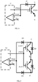
- a common IGBT short-circuit protection method is to detect a voltage drop Vce between the collector and emitter of the IGBT, feed it into a non-inverting input terminal of a comparator in a drive optocoupler, and perform a comparison with a fixed valve value of an inverting input terminal.
- the principle thereof is that a rapid increase in Ic is followed by an increase in Vce, according to a relationship between Vce and Ic, wherein Vce is the voltage drop between the collector and emitter, and Ic is current between the collector and emitter.
- Vce is the voltage drop between the collector and emitter
- Ic current between the collector and emitter.
- the present invention proposes an improved IGBT bidirectional short-circuit detection and protection circuit, which is capable of realizing bidirectional short-circuit protection of two reverse-series-connected IGBTs, with no need to add an extra short-circuit protection circuit.
- An embodiment of the present invention provides an IGBT short-circuit detection and protection circuit, for IGBT short-circuit detection and protection, the circuit comprising: a drive unit, for generating a PWM drive signal to control switching on of the IGBT; a comparison unit, having a threshold pin and a detection pin, the threshold pin being connected to a threshold voltage, the detection pin being connected to a collector of the IGBT via a diode, the detection pin supplying a detection current for the diode, and a cathode of the diode being connected to the collector of the IGBT, wherein when a voltage at the detection pin is greater than the threshold voltage, the drive unit controls the IGBT so that same switches off.
- an emitter of the IGBT is connected to a reference ground voltage.
- the drive unit and the comparison unit are integrated in a single chip.
- Another embodiment of the present invention provides an IGBT short-circuit detection and protection circuit, for subjecting a pair of reverse-series-connected IGBTs to short-circuit detection and protection, the pair of IGBTs comprising a first IGBT and a second IGBT, and an emitter of the first IGBT being connected to an emitter of the second IGBT, the circuit comprising: a drive unit, an output terminal thereof outputting a PWM drive signal, and being connected to gate terminals of the first IGBT and the second IGBT, to simultaneously control switching on of the first IGBT and the second IGBT; a comparison unit, having a threshold pin and a detection pin, the threshold pin being connected to a threshold voltage, the detection pin being connected to collectors of the first IGBT and the second IGBT via a first diode and a second diode respectively, the detection pin supplying a detection current for the first diode and the second diode, and cathodes of the first diode and the second dio
- first flyback diode and a second flyback diode are reverse-parallel-connected between the collector and emitter of the first IGBT and the second IGBT respectively.
- the drive unit and the comparison unit are integrated in a single chip.
- an IGBT-based controllable rectifier circuit comprising: a three-phase AC power supply and three reverse-series-connected IGBT units, wherein each reverse-series-connected IGBT unit comprises a first IGBT and a second IGBT, an emitter of the first IGBT is connected to an emitter of the second IGBT, a collector of one of the first IGBT and the second IGBT is connected to one phase of the three-phase AC power supply, and a collector of the other one of the first IGBT and the second IGBT is connected to a collector of one of the other two IGBT units, wherein each IGBT unit further comprises: a drive unit, an output terminal thereof outputting a PWM drive signal, and being connected to gate terminals of the first IGBT and the second IGBT, to simultaneously control switching on of the first IGBT and the second IGBT; a comparison unit, having a threshold pin and a detection pin, the threshold pin being connected to a threshold voltage,
- first flyback diode and a second flyback diode are reverse-parallel-connected between the collector and emitter of the first IGBT and the second IGBT respectively.
- each phase of the three-phase AC power supply is connected to one of the IGBT units via an inductance.
- the drive unit and the comparison unit are integrated in a single chip.
- the IGBT short-circuit detection and protection circuit of the present invention makes use of the characteristic that if a short circuit occurs when the IGBT is conducting, then the current direction is determined by the polarity of voltage across it, and realizes bidirectional short-circuit protection of two reverse-series-connected IGBTs by merely adding a diode for each IGBT, with no need to add an extra short-circuit protection circuit.
- the present invention makes use of a drive chip containing a comparator, simultaneously realizing a bidirectional short-circuit protection function for two reverse-series-connected IGBTs; the bidirectional short-circuit protection functions are both triggered by hardware, realizing soft turn-off, thereby simplifying the circuit while greatly reducing costs, and increasing the circuit stability.
- the present invention provides an IGBT short-circuit detection and protection circuit, for IGBT short-circuit detection and protection.
- the circuit comprises a drive chip IC containing a comparator; the drive chip can output a PWM drive signal to control the switching of the IGBT on and off, i.e. when the PWM drive signal is HIGH, the IGBT is switched on, and when the PWM drive signal is LOW, the IGBT is switched off.
- the comparator in the drive chip IC has a threshold pin and a detection pin Vdesat.
- the threshold pin is an inverting input terminal, and is connected to a threshold voltage; the detection pin Vdesat is a non-inverting input terminal, and is connected to a collector C of an IGBT via a diode D.
- the detection pin Vdesat supplies a detection current for the diode D by means of a constant current source in the drive chip, e.g. a detection current of magnitude 250 uA.
- a cathode of the diode D is connected to the collector C of the IGBT, the collector C of the IGBT is connected to an input voltage, and an emitter E of the IGBT is connected to a drive signal reference ground voltage.
- the present invention also provides an IGBT short-circuit detection and protection circuit, for subjecting a pair of reverse-series-connected IGBTs to short-circuit detection and protection.
- the pair of IGBTs comprises a first IGBT (IGBT 1) and a second IGBT (IGBT 2).
- An emitter E of the first IGBT is connected to an emitter E of the second IGBT, and a collector of the first IGBT is connected to an input voltage.
- An output terminal of a drive chip IC containing a comparator outputs a PWM drive signal, and is connected to gate terminals of the first IGBT and the second IGBT, to simultaneously control the switching on of the first IGBT and the second IGBT.
- the comparator in the drive chip IC has a threshold pin and a detection pin Vdesat; the threshold pin is connected to a threshold voltage, and the detection pin Vdesat is connected to the collectors of the first IGBT and the second IGBT via a first high voltage isolating diode D1 and a second high voltage isolating diode D3 respectively.
- the detection pin Vdesat supplies a detection current for the first high voltage isolating diode D1 and the second high voltage isolating diode D3; cathodes of the first high voltage isolating diode D1 and the second high voltage isolating diode D3 are connected to the collectors C of the first IGBT and the second IGBT respectively.
- first flyback diode D2 and a second flyback diode D4 are reverse-parallel-connected between the collector C and emitter E of the first IGBT and the second IGBT respectively.
- the expression "reverse-parallel-connected" used here means that only one of the IGBT and the flyback diode can conduct.
- the PWM drive signal outputted by the drive chip IC changes to LOW, and the first IGBT and the second IGBT switch off.
- a Vce voltage acquisition unit D1 for current in a first direction will acquire the voltage drop across the IGBT1 in real time, and feed it into the non-inverting input terminal Vdesat of the comparator for comparison with a valve value of the inverting input terminal, thereby realizing short-circuit protection for current in the first direction;
- a Vce voltage acquisition unit D3 for current in a second direction will acquire the voltage drop across the IGBT2 in real time, and feed it into the non-inverting input terminal Vdesat of the comparator for comparison with a valve value of the inverting input terminal, thereby realizing short-circuit protection for current in the second direction.
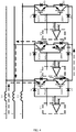
- the abovementioned circuit of the present invention provides an IGBT-based controllable rectifier circuit; as shown in fig. 3 , the rectifier circuit comprises a three-phase AC power supply having three phase inputs R, S and T, with each phase input being connected to a corresponding energy storage inductance L1/L2/L3 respectively, and each phase output being connected to a reverse-series-connected IGBT unit respectively.
- an R phase output is connected to a first reverse-series-connected IGBT unit via the inductance L1;
- the first IGBT unit comprises a first IGBT (IGBT 1) and a second IGBT (IGBT 2), an emitter of the first IGBT (IGBT 1) being connected to an emitter of the second IGBT (IGBT 1), a collector of the first IGBT (IGBT 1) being connected to the R phase, and a collector of the second IGBT (IGBT 2) being connected to a collector of one of the other two IGBT units.
- the first IGBT unit further comprises a short-circuit detection and protection circuit; the short-circuit detection and protection circuit comprises high voltage isolating diodes and flyback diodes, and a first drive chip IC1 containing a comparator.
- An output terminal of the first drive chip IC1 outputs a PWM1 drive signal, and is connected to gate terminals of the first IGBT and the second IGBT, to simultaneously control the switching on of the first IGBT and the second IGBT.
- the comparator in the first drive chip IC1 has a threshold pin and a detection pin Vdesat; the threshold pin is connected to a threshold voltage, and the detection pin Vdesat is connected to the collectors of the first IGBT and the second IGBT via a first diode D1 and a second diode D3 respectively.
- the detection pin Vdesat supplies a detection current for the first diode D1 and the second diode D3; cathodes of the first diode D1 and the second diode D3 are connected to the collectors C of the first IGBT and the second IGBT respectively.
- a first flyback diode D2 and a second flyback diode D4 are reverse-parallel-connected between the collector C and emitter E of the first IGBT and the second IGBT respectively.
- an L phase output is connected to a second reverse-series-connected IGBT unit via the inductance L2 and a T phase output is connected to a third reverse-series-connected IGBT unit via the inductance L3.
- the second reverse-series-connected IGBT unit is formed of a third IGBT (IGBT 3), a fourth IGBT (IGBT 4), a third high voltage isolating diode D5, a fourth high voltage isolating diode D7, a third flyback diode D6, a fourth flyback diode D8 and a second drive chip IC2.
- the third reverse-series-connected IGBT unit is formed of a fifth IGBT (IGBT 5), a sixth IGBT (IGBT 5), a fifth high voltage isolating diode D9, a sixth high voltage isolating diode D11, a fifth flyback diode D10, a sixth flyback diode D12 and a third drive chip IC3.
- the connections of the second and third reverse-series-connected IGBT units are similar to the connections of the first reverse-series-connected IGBT unit, so are not described superfluously here.
- collectors of the second IGBT, the fourth IGBT and the sixth IGBT are connected to each other.
- the content described above forms the IGBT-based controllable rectifier circuit of the present invention; the principle of rectification thereof is similar to that of a conventional three-switch two-level APFC circuit, so is not described superfluously here.
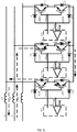
- Short-circuit detection and protection of the IGBTs in the controllable rectifier circuit in this embodiment is explained below with reference to figs. 4 and 5 .
- a current between the R phase and the S phase is taken as an example for illustration; other inter-phase scenarios are similar.
- the direction of current is R -> L1 -> IGBT1 -> D4 -> IGBT4 -> D6 -> L2 - > S (the direction indicated by the dotted-line arrow in fig. 4 ).
- the comparator and the drive signal for controlling switching on of the IGBT are integrated in the drive chip IC; this enables the circuit to be simplified, to provide stability, but separate devices could also be used as required, i.e. with the IGBT drive signal and detection of the voltage between the collector and emitter being realized by means of a drive unit providing a drive signal PWM and a comparison unit respectively. This could likewise realize the abovementioned IGBT short-circuit detection and protection functions; a specific circuit is shown in fig. 6 , and will be easily understood by those skilled in the art based on the description above, so is not described superfluously here.
Landscapes
- Engineering & Computer Science (AREA)
- Power Engineering (AREA)
- Power Conversion In General (AREA)
- Rectifiers (AREA)
- Electronic Switches (AREA)
- Inverter Devices (AREA)
Applications Claiming Priority (2)
| Application Number | Priority Date | Filing Date | Title |
|---|---|---|---|
| CN201520755608.5U CN204967246U (zh) | 2015-09-25 | 2015-09-25 | Igbt短路检测保护电路及基于igbt的可控整流电路 |
| PCT/CN2016/079835 WO2017049900A1 (fr) | 2015-09-25 | 2016-04-21 | Circuit de détection et de protection de court-circuit d'igbt et circuit redresseur commandé à base d'igbt |
Publications (2)
| Publication Number | Publication Date |
|---|---|
| EP3355433A1 true EP3355433A1 (fr) | 2018-08-01 |
| EP3355433A4 EP3355433A4 (fr) | 2019-06-19 |
Family
ID=55062287
Family Applications (1)
| Application Number | Title | Priority Date | Filing Date |
|---|---|---|---|
| EP16847782.6A Withdrawn EP3355433A4 (fr) | 2015-09-25 | 2016-04-21 | Circuit de détection et de protection de court-circuit d'igbt et circuit redresseur commandé à base d'igbt |
Country Status (7)
| Country | Link |
|---|---|
| US (2) | US20180287372A1 (fr) |
| EP (1) | EP3355433A4 (fr) |
| JP (1) | JP2018530297A (fr) |
| KR (1) | KR20180095503A (fr) |
| CN (1) | CN204967246U (fr) |
| TW (1) | TWM531088U (fr) |
| WO (1) | WO2017049900A1 (fr) |
Families Citing this family (19)
| Publication number | Priority date | Publication date | Assignee | Title |
|---|---|---|---|---|
| CN204967246U (zh) * | 2015-09-25 | 2016-01-13 | 江森自控空调冷冻设备(无锡)有限公司 | Igbt短路检测保护电路及基于igbt的可控整流电路 |
| US11152780B2 (en) * | 2017-08-31 | 2021-10-19 | Eaton Intelligent Power Limited | Adjustable speed drive with integrated solid-state circuit breaker and method of operation thereof |
| CN107679353B (zh) * | 2017-11-20 | 2021-02-02 | 重庆大学 | 模拟压接式igbt器件失效短路机理的有限元建模方法 |
| CN110445091B (zh) * | 2018-05-03 | 2024-10-25 | 北京北秦安全技术有限公司 | 一种单相灭弧式短路保护器 |
| CN110474626B (zh) * | 2019-05-10 | 2024-08-06 | 中智电气南京有限公司 | 一种基于数控车床伺服驱动器的igbt保护电路 |
| CN110445100B (zh) * | 2019-07-22 | 2024-07-19 | 江苏云意电气股份有限公司 | 一种igbt退饱和保护和驱动电源欠压保护电路 |
| CN110780230B (zh) * | 2019-11-26 | 2024-11-15 | 晟合微电子(肇庆)有限公司 | 一种ic模组开路或短路检测装置及检测方法 |
| CN111257716B (zh) * | 2020-02-24 | 2022-06-10 | 漳州科华技术有限责任公司 | Igbt过流检测电路及芯片和电子设备 |
| CN111371072B (zh) * | 2020-04-21 | 2024-07-02 | 东莞市台诺电子有限公司 | 不间断电源输出短路过流保护电路 |
| CN111668823B (zh) * | 2020-06-30 | 2025-03-11 | 博格华纳驱动系统(苏州)有限公司 | 一种igbt过流保护电路 |
| CN112203385A (zh) * | 2020-09-27 | 2021-01-08 | 深圳拓邦股份有限公司 | 一种led控制及短路保护电路和共阴极led电路 |
| CN112670955A (zh) * | 2020-12-10 | 2021-04-16 | 合肥同智机电控制技术有限公司 | 一种基于双n沟道igbt串联的电机继电保护装置 |
| CN114629086A (zh) * | 2020-12-12 | 2022-06-14 | 东莞市众达安智能科技有限公司 | 一种交流电源短路灭弧保护的控制系统 |
| WO2022149321A1 (fr) * | 2021-01-07 | 2022-07-14 | 株式会社村田製作所 | Module de commutation |
| CN115603725B (zh) * | 2021-06-28 | 2025-01-14 | 比亚迪股份有限公司 | Igbt驱动保护控制电路和设备 |
| CN113556114B (zh) * | 2021-07-22 | 2025-07-15 | 苏州高新有轨电车集团有限公司 | 一种基于浮地电流斜率抑制的igbt栅极驱动器 |
| CN113938118B (zh) * | 2021-10-19 | 2025-03-25 | 中国科学院上海微系统与信息技术研究所 | 去饱和短路保护电路、功率器件短路保护电路及测试电路 |
| CN116449168A (zh) * | 2023-04-11 | 2023-07-18 | 国网智能电网研究院有限公司 | 一种驱动器保护功能测试电路及测试方法 |
| CN116953464A (zh) * | 2023-07-31 | 2023-10-27 | 荣信汇科电气股份有限公司 | 一种igbt功率模块全工况短路试验方法及装置 |
Family Cites Families (20)
| Publication number | Priority date | Publication date | Assignee | Title |
|---|---|---|---|---|
| US4429339A (en) * | 1982-06-21 | 1984-01-31 | Eaton Corporation | AC Transistor switch with overcurrent protection |
| US4620258A (en) * | 1984-03-30 | 1986-10-28 | General Electric Company | Circuit for self-commutated turn-off of latched devices, such as of the insulated-gate transistor/rectifier type |
| FR2735299B1 (fr) * | 1995-06-09 | 1997-08-22 | Legrand Sa | Interrupteur statique a protection integree |
| DE10014641C2 (de) * | 2000-03-24 | 2002-03-07 | Siemens Ag | Schaltungsanordnung mit einem bidirektionalen Leistungsschalter in Common Kollektor Mode und mit einer aktiven Überspannungsschutzvorrichtung |
| US6549438B2 (en) * | 2001-04-30 | 2003-04-15 | Precision Automation, Inc. | AC-to-DC converter circuit utilizing IGBT's for improved efficiency |
| JP3932841B2 (ja) * | 2001-08-29 | 2007-06-20 | 株式会社日立製作所 | 半導体電力変換装置 |
| FR2845480A1 (fr) * | 2002-10-07 | 2004-04-09 | St Microelectronics Sa | Protection d'un interrupteur en alternatif |
| JP2004222367A (ja) * | 2003-01-10 | 2004-08-05 | Toshiba Corp | ゲート駆動装置及び電力変換装置 |
| JP4223331B2 (ja) * | 2003-06-13 | 2009-02-12 | 株式会社日立製作所 | 電力制御用半導体素子の保護装置及びそれを備えた電力変換装置 |
| JP2006033723A (ja) * | 2004-07-21 | 2006-02-02 | Sharp Corp | 電力制御用光結合素子およびこの電力制御用光結合素子を用いた電子機器 |
| JP5115829B2 (ja) * | 2010-06-09 | 2013-01-09 | 株式会社デンソー | スイッチング装置 |
| CN102332705B (zh) * | 2011-10-25 | 2013-12-25 | 杭州日鼎控制技术有限公司 | 大功率变频装置igbt短路保护电路 |
| JP5895319B2 (ja) * | 2012-01-18 | 2016-03-30 | 九州電力株式会社 | Smrコンバータ |
| CN103973277B (zh) * | 2013-02-05 | 2017-06-09 | 通用电气公司 | 绝缘栅双极型晶体管的短路保护电路和方法 |
| US9571091B2 (en) * | 2013-12-06 | 2017-02-14 | Astec International Limited | Methods for overdriving a base current of an emitter switched bipolar junction transistor and corresponding circuits |
| CN104078939B (zh) * | 2014-06-25 | 2018-02-27 | 台达电子企业管理(上海)有限公司 | 功率变换器、短路保护电路与控制方法 |
| US9435833B2 (en) * | 2014-07-23 | 2016-09-06 | Freescale Semiconductor, Inc. | Resistance detection for integrated circuit driver based on parasitic inductance |
| US9331474B1 (en) * | 2014-10-08 | 2016-05-03 | Stmicroelectronics International N.V. | Over-voltage protection circuit for a drive transistor |
| CN204536486U (zh) * | 2014-11-19 | 2015-08-05 | 湖南南车时代电动汽车股份有限公司 | 一种igbt退饱和检测电路 |
| CN204967246U (zh) * | 2015-09-25 | 2016-01-13 | 江森自控空调冷冻设备(无锡)有限公司 | Igbt短路检测保护电路及基于igbt的可控整流电路 |
-
2015
- 2015-09-25 CN CN201520755608.5U patent/CN204967246U/zh not_active Expired - Lifetime
-
2016
- 2016-04-21 KR KR1020187011172A patent/KR20180095503A/ko not_active Withdrawn
- 2016-04-21 EP EP16847782.6A patent/EP3355433A4/fr not_active Withdrawn
- 2016-04-21 US US15/762,509 patent/US20180287372A1/en not_active Abandoned
- 2016-04-21 JP JP2018516031A patent/JP2018530297A/ja active Pending
- 2016-04-21 WO PCT/CN2016/079835 patent/WO2017049900A1/fr not_active Ceased
- 2016-04-21 TW TW105205618U patent/TWM531088U/zh unknown
-
2019
- 2019-06-25 US US16/452,313 patent/US20190386483A1/en not_active Abandoned
Also Published As
| Publication number | Publication date |
|---|---|
| WO2017049900A1 (fr) | 2017-03-30 |
| TWM531088U (zh) | 2016-10-21 |
| EP3355433A4 (fr) | 2019-06-19 |
| CN204967246U (zh) | 2016-01-13 |
| JP2018530297A (ja) | 2018-10-11 |
| US20190386483A1 (en) | 2019-12-19 |
| KR20180095503A (ko) | 2018-08-27 |
| US20180287372A1 (en) | 2018-10-04 |
Similar Documents
| Publication | Publication Date | Title |
|---|---|---|
| EP3355433A1 (fr) | Circuit de détection et de protection de court-circuit d'igbt et circuit redresseur commandé à base d'igbt | |
| US11025163B2 (en) | Boost power conversion circuit | |
| CN103516244B (zh) | 多级电力变换电路的保护控制系统 | |
| US9570973B2 (en) | Bridgeless power factor correction circuit and control method utilizing control module to control current flow in power module | |
| EP2662968B1 (fr) | Onduleur à trois niveaux | |
| US10236879B2 (en) | Thyristor driving apparatus | |
| EP2806444A1 (fr) | Dispositif et procédé pour couper le courant dans un système de transmission ou de distribution de puissance | |
| CN106688183A (zh) | 自灭弧式半导体元件的短路保护电路 | |
| EP3813239B1 (fr) | Circuit à alimentation autonome et dispositif de conversion de courant | |
| JP2022544998A (ja) | 電力変換装置の駆動回路及びその応用装置 | |
| JP5619673B2 (ja) | スイッチング回路及び半導体モジュール | |
| US9716445B2 (en) | Inverter grid-connected system and method for implementing three-phase alternating current grid-connected transition | |
| CN105490511A (zh) | 一种t型三电平igbt驱动电路 | |
| US20250015713A1 (en) | Totem-pole power factor correction circuit, power supply equipment | |
| US7248093B2 (en) | Bipolar bootstrap top switch gate drive for half-bridge semiconductor power topologies | |
| CN205377644U (zh) | 一种t型三电平igbt驱动电路 | |
| CN113541658A (zh) | 通信系统、栅极驱动器系统和用于栅极驱动器通信的方法 | |
| EP2672617A1 (fr) | Convertisseur abaisseur de tension avec protection de courant inverse et système photovoltaïque | |
| US9755498B2 (en) | Semiconductor device, and inverter, converter and power conversion device employing the same | |
| US10135353B2 (en) | Unidirectional matrix converter with regeneration system | |
| CN103828205B (zh) | 用于控制电力开关的电源 | |
| US20140091738A1 (en) | Inverter Circuit having Switching Means Operating with Linear Operation | |
| CN105553313A (zh) | 具有保护结构的npc型三电平逆变器驱动电路及方法 | |
| CN105917571A (zh) | 电机控制电路、方法、电机系统、无人机及其控制方法 | |
| WO2012050042A1 (fr) | Régulateur, appareil de chargement de batterie et système de chargement de batterie |
Legal Events
| Date | Code | Title | Description |
|---|---|---|---|
| PUAI | Public reference made under article 153(3) epc to a published international application that has entered the european phase |
Free format text: ORIGINAL CODE: 0009012 |
|
| 17P | Request for examination filed |
Effective date: 20180323 |
|
| AK | Designated contracting states |
Kind code of ref document: A1 Designated state(s): AL AT BE BG CH CY CZ DE DK EE ES FI FR GB GR HR HU IE IS IT LI LT LU LV MC MK MT NL NO PL PT RO RS SE SI SK SM TR |
|
| AX | Request for extension of the european patent |
Extension state: BA ME |
|
| DAV | Request for validation of the european patent (deleted) | ||
| DAX | Request for extension of the european patent (deleted) | ||
| A4 | Supplementary search report drawn up and despatched |
Effective date: 20190520 |
|
| RIC1 | Information provided on ipc code assigned before grant |
Ipc: H02M 1/32 20070101ALI20190514BHEP Ipc: H03K 17/08 20060101ALI20190514BHEP Ipc: H02H 7/20 20060101AFI20190514BHEP Ipc: H03K 17/082 20060101ALI20190514BHEP Ipc: H02H 3/20 20060101ALI20190514BHEP Ipc: H02H 7/12 20060101ALI20190514BHEP |
|
| STAA | Information on the status of an ep patent application or granted ep patent |
Free format text: STATUS: THE APPLICATION IS DEEMED TO BE WITHDRAWN |
|
| 18D | Application deemed to be withdrawn |
Effective date: 20191217 |