EP3355441B1 - Moteur électrique et son rotor à aimant permanent du type tangentiel - Google Patents
Moteur électrique et son rotor à aimant permanent du type tangentiel Download PDFInfo
- Publication number
- EP3355441B1 EP3355441B1 EP16847836.0A EP16847836A EP3355441B1 EP 3355441 B1 EP3355441 B1 EP 3355441B1 EP 16847836 A EP16847836 A EP 16847836A EP 3355441 B1 EP3355441 B1 EP 3355441B1
- Authority
- EP
- European Patent Office
- Prior art keywords
- permanent magnet
- rotor
- permanent magnets
- magnetism isolating
- iron core
- Prior art date
- Legal status (The legal status is an assumption and is not a legal conclusion. Google has not performed a legal analysis and makes no representation as to the accuracy of the status listed.)
- Active
Links
Images


Classifications
-
- H—ELECTRICITY
- H02—GENERATION; CONVERSION OR DISTRIBUTION OF ELECTRIC POWER
- H02K—DYNAMO-ELECTRIC MACHINES
- H02K1/00—Details of the magnetic circuit
- H02K1/06—Details of the magnetic circuit characterised by the shape, form or construction
- H02K1/22—Rotating parts of the magnetic circuit
- H02K1/27—Rotor cores with permanent magnets
- H02K1/2706—Inner rotors
- H02K1/272—Inner rotors the magnetisation axis of the magnets being perpendicular to the rotor axis
- H02K1/274—Inner rotors the magnetisation axis of the magnets being perpendicular to the rotor axis the rotor consisting of two or more circumferentially positioned magnets
- H02K1/2753—Inner rotors the magnetisation axis of the magnets being perpendicular to the rotor axis the rotor consisting of two or more circumferentially positioned magnets the rotor consisting of magnets or groups of magnets arranged with alternating polarity
- H02K1/276—Magnets embedded in the magnetic core, e.g. interior permanent magnets [IPM]
- H02K1/2766—Magnets embedded in the magnetic core, e.g. interior permanent magnets [IPM] having a flux concentration effect
- H02K1/2773—Magnets embedded in the magnetic core, e.g. interior permanent magnets [IPM] having a flux concentration effect consisting of tangentially magnetized radial magnets
-
- H—ELECTRICITY
- H01—ELECTRIC ELEMENTS
- H01F—MAGNETS; INDUCTANCES; TRANSFORMERS; SELECTION OF MATERIALS FOR THEIR MAGNETIC PROPERTIES
- H01F13/00—Apparatus or processes for magnetising or demagnetising
- H01F13/003—Methods and devices for magnetising permanent magnets
-
- H—ELECTRICITY
- H02—GENERATION; CONVERSION OR DISTRIBUTION OF ELECTRIC POWER
- H02K—DYNAMO-ELECTRIC MACHINES
- H02K1/00—Details of the magnetic circuit
- H02K1/06—Details of the magnetic circuit characterised by the shape, form or construction
- H02K1/22—Rotating parts of the magnetic circuit
- H02K1/27—Rotor cores with permanent magnets
-
- H—ELECTRICITY
- H02—GENERATION; CONVERSION OR DISTRIBUTION OF ELECTRIC POWER
- H02K—DYNAMO-ELECTRIC MACHINES
- H02K2213/00—Specific aspects, not otherwise provided for and not covered by codes H02K2201/00 - H02K2211/00
- H02K2213/03—Machines characterised by numerical values, ranges, mathematical expressions or similar information
Definitions
- the present invention relates to a technical field of electric motor devices, and more particularly, to an electric motor and a tangential type permanent magnet rotor thereof.
- An electric motor of a permanent magnet tangential-magnetization structure can generate a higher air gap flux density than a permanent magnet radial-magnetization electric motor due to its magnetism gathering effect.
- the electric motor has a relatively large torque/current ratio and torque/volume ratio and is increasingly applied to an occasion such as a servo system, electric traction, office automation and a household electrical appliance.
- a tangential permanent magnet electric motor due to a magnetic circuit structure in which single permanent magnets are in parallel connection, operating points of the permanent magnets are lower than a radial magnetic electric motor. Moreover, most permanent magnets are of a rectangular shape, and widths thereof along a radial direction of a rotor are almost the same. However, the intensities of a demagnetized field on different parts of the permanent magnets are different and this is the case for the operating points on different parts of the same permanent magnet. Hence, the overall demagnetization resistance of the electric motor is reduced. Particularly, the closer the permanent magnets are to an outer side of the rotor, the stronger the intensities of the demagnetized field are borne, such that an efficiency of the electric motor is reduced.
- EP 2658091A1 discloses a rotor assembly, the rotor assembly includes a rotor portion provided with an insertion hole into which a rotating shaft is inserted and a magnet inserted into an embedded hole radially formed at a cross section axially vertical to the shaft of the rotor portion outwardly from the rotor portion, wherein the magnet is formed so that a width in a direction vertical to a radial direction of the magnet gradually increases from the shaft radially outwardly from the rotor portion.
- US2014/0361656A1 discloses a rotor for rotating electric machine and rotating electrical machine comprising such a rotor, the rotor comprises of a plurality of alternating north poles and south poles formed from a plurality of permanent magnets 3 having a radial polygonal section and arranged in first recesses 4. These first recesses extend axially and are distributed regularly between a circumferential portion 5 and a central portion 6 of the magnetic mass of the rotor in such a way as to define a plurality of circumferential polar sections 10.
- the radical section comprises a substantially rectangular portion 8 next to the circumferential portion adjacent to a substantially trapezoidal portion 7 next to the central portion.
- EP2293421A2 discloses another tangential type permanent magnet rotor that has an even number of first permanent magnets aligned in a circumferential direction of the rotor.
- the present invention is intended to provide a tangential type permanent magnet rotor, so as to reduce a local demagnetization of permanent magnets and ensure an efficiency of an electric motor and increasing the torque.
- the present invention further provides an electric motor having the above tangential type permanent magnet rotor.
- the present invention provides a tangential type permanent magnet rotor, which comprises a rotor iron core and permanent magnets provided on the rotor iron core, a width of one side, close to an outer edge of the rotor iron core, of each of the permanent magnets is H2; and a width of one side, close to a center of the rotor iron core, of each of the permanent magnets is H1, wherein H2>H1.
- the rotor iron core is provided with an outside magnetism isolating bridge provided at one side, close to the outer edge of the rotor iron core, of each of the permanent magnets
- the outside magnetism isolating bridge comprises a first outside magnetism isolating bridge provided at a front side of the rotation direction of the tangential type permanent magnet rotor, and a second outside magnetism isolating bridge provided at a rear side of the rotation direction of the tangential type permanent magnet rotor, a thickness B1 of the first outside magnetism isolating bridge is greater than a thickness B2 of the second outside magnetism isolating bridge; a length D1 of the first outside magnetism isolating bridge is smaller than a length D2 of the second outside magnetism isolating bridge.
- the rotor iron core is further provided with an inside magnetism isolating structure provided between sides, close to the center of the rotor iron core, of the adjacent two of the permanent magnets, a cross section, perpendicular to an axial line of the tangential type permanent magnet rotor, of the inside magnetism isolating structure is of a triangular or trapezoidal structure; a small end of the inside magnetism isolating structure is towards the center of the rotor iron core.
- a first inside magnetism isolating bridge is formed between the inside magnetism isolating structure and each of the permanent magnets provided at a front side of a rotation direction of the tangential type permanent magnet rotor;
- a second inside magnetism isolating bridge is formed between the inside magnetism isolating structure and each of the permanent magnets provided at a rear side of the rotation direction of the tangential type permanent magnet rotor, a thickness C1 of the first inside magnetism isolating bridge is greater than a thickness C2 of the second inside magnetism isolating bridge.
- the present invention further provides an electric motor, comprising a tangential type permanent magnet rotor; the tangential type permanent magnet rotor is the tangential type permanent magnet rotor described above.
- the tangential type permanent magnet rotor provided by the present invention enables the width H2 of a permanent magnet part close to the outer edge of the rotor iron core to be larger, and enables the width H1 of a permanent magnet part close to the center of the rotor iron core to be smaller, so that operating points at two sides (the side close to the center of the rotor iron core and the side close to the outer edge of the rotor iron core) of each of the permanent magnets and operating points of a permanent magnet with equal widths in the related art have relatively high consistency, thus reducing the effect of local demagnetization of the permanent magnets, and ensuring the efficiency of the electric motor.
- the present invention further provides the electric motor having the above tangential type permanent magnet rotor.
- the tangential type permanent magnet rotor has the above technical effects, so the electric motor having the tangential type permanent magnet rotor also should have the same technical effects, which will not be described in detail here.
- the core of the present invention is to provide a tangential type permanent magnet rotor so as to reduce a local demagnetization effect of permanent magnets and ensuring an efficiency of an electric motor and increasing the generated torque.
- the present invention further provides an electric motor having the above tangential type permanent magnet rotor.
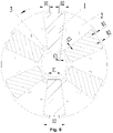
- Fig. 1 is a first structural schematic diagram of a tangential type permanent magnet rotor provided by the present invention.
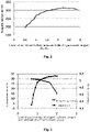
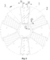
- Fig. 2 is a systematic diagram illustrating a relationship between a width ratio of a permanent magnet and a magnetic linkage of a tangential type permanent magnet rotor
- the tangential type permanent magnet rotor comprises a rotor iron core 2 and permanent magnets 1 provided on the rotor iron core 2, wherein an even number of the permanent magnets 1 are provided and the permanent magnets 1 are evenly provided on the rotor iron core 2; homopolarities of adjacent two permanent magnets 1 are opposite.
- a width of one side, close to an outer edge of the rotor iron core 2, of each of the permanent magnets 1 is H2; and a width of one side, close to a center of the rotor iron core 2, of each of the permanent magnets 1 is H1, wherein H2>H1.
- the tangential type permanent magnet rotor provided by the embodiment of the present invention enables the width H2 of a permanent magnet part close to the outer edge of the rotor iron core 2 to be larger, and enables the width H1 of a permanent magnet part close to the center of the rotor iron core 2 to be smaller, so that operating points at two sides (a side close to the center of the rotor iron core 2 and a side close to the outer edge of the rotor iron core 2) of each of the permanent magnets 1 and operating points of a permanent magnet with equal widths in the prior art have relatively high consistency, thus reducing an effect of local demagnetization of the permanent magnets, and ensuring an efficiency of the electric motor.
- a value range for the width at two sides of each of the permanent magnets 1 is as follows: 2.2 ⁇ H2/H1 ⁇ 1.2.
- a reversed magnetic field of a stator externally added on the rotor is more applied to positions, close to the inside of the rotor, of the permanent magnets, such that the permanent magnets at positions with relatively high operating points bear a large intensity of the demagnetizing field, and those at positions with relatively low operating points bear a small intensity of the demagnetizing field.
- the magnetic field of each of the whole permanent magnets is more evenly, and the air gap magnetic flux density generated by the permanent magnets of the electric motor has a lower harmonic content.
- the higher H2/H1 ratio is not the better.
- a stator magnetic linkage is basically no longer increased and thus the stator magnetic flux is no longer increased. Therefore, in order to ensure a utilization rate of the permanent magnets 1 and reduce the cost, in each of the permanent magnets 1, 2.2 ⁇ H2/H1.
- the stator magnetic linkage is increased more obviously, such that the electric motor has a higher efficiency.
- a rotor magnetic flux also enters the stator via a silicon steel sheet magnetic conductive passage in the middle of two adjacent permanent magnets.
- the maximum included angle of the magnetic conductive passage between adjacent two permanent magnets 1 is A2, and the minimum included angle for the permanent magnets 1 is A1, A2 ⁇ A1.
- the A1 is an included angle of connecting lines that are respectively between two ends of a surface at one side, close to the outer edge of the rotor iron core 2, of each of the permanent magnets 1 and the center of the rotor iron core 2;
- the A2 is an included angle of connecting lines that are respectively between two ends of a surface at one side, close to the outer edge of the rotor iron core 2, of the magnetic conductive passage between the adjacent two of the permanent magnets 1 and the center of the rotor iron core 2.
- the magnetic conductive passage between the adjacent two permanent magnets 1 are not obviously saturated under the heavy load, such that an output torque of the electric motor is not reduced.
- the larger magnetic conductive passages between the permanent magnets are not the better.
- the A2 are increased, it is easy to cause that a demagnetization resistance of the electric motor is reduced.
- the A2 is smaller than or equal to 1.6A1.
- 1 ⁇ A2/A1 ⁇ 1.6 is smaller than or equal to 1.
- each of the permanent magnets 1 is of an isosceles trapezoid; an upper bottom of the isosceles trapezoid is provided at a side close to the center of the rotor iron core 2.
- each of the permanent magnets 1 is of a centrosymmetric structure, and a center line of each of the permanent magnets 1 is a middle line of the isosceles trapezoid.
- a cross section, perpendicular to an axial line of the tangential type permanent magnet rotor, of each of the permanent magnets 1 is of a non-isosceles trapezoid, an upper bottom of the non-isosceles trapezoid is provided at a side close to the center of the rotor iron core 2, and a waist of the non-isosceles trapezoid comprises a first waist provided at a front side of a rotation direction of the tangential type permanent magnet rotor and a second waist provided at a rear side of the rotation direction of the tangential type permanent magnet rotor; a length of the first waist is greater than that of the second waist.
- an area of a surface, positioned at the front side of the rotation direction of the tangential type permanent magnet rotor, of each of the permanent magnets 1 is greater than that of a surface, positioned at the rear side of the rotation direction of the tangential type permanent magnet rotor, of each of the permanent magnets 1, so that the permanent magnets 1 generate a larger stator magnetic flux.
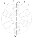
- the rotor iron core 2 is provided with an outside magnetism isolating bridge provided at one side, close to the outer edge of the rotor iron core 2, of each of the permanent magnets 1.
- Each of the outside magnetism isolating bridges comprises a first outside magnetism isolating bridge provided at the front side of the rotation direction of the tangential type permanent magnet rotor, and a second outside magnetism isolating bridge provided at the rear side of the rotation direction of the tangential type permanent magnet rotor. That is, a sum of the first outside magnetism isolating bridge and the second outside magnetism isolating bridge is smaller than the width H2 of the corresponding each of the permanent magnets 1.
- a thickness B1 of each of the first outside magnetism isolating bridges is greater than a thickness B2 of each of the second outside magnetism isolating bridges, and a length D1 of each of the first outside magnetism isolating bridges is smaller than a length D2 of each of the second outside magnetism isolating bridges.
- the rotor iron core 2 is further provided with an inside magnetism isolating structure provided between certain sides, close to the center of the rotor iron core 2, of the adjacent two of the permanent magnets 1.
- a cross section, perpendicular to an axial line of the tangential type permanent magnet rotor, of the inside magnetism isolating structure is of a triangular or trapezoidal structure; a small end of the inside magnetism isolating structure is towards the center of the rotor iron core 2.
- Two magnetism isolating bridges are provided between the adjacent two permanent magnets 1. To simplify the structure here, the two magnetism isolating bridges are respectively provided in the inside magnetism isolating structure.
- each of the permanent magnets 1 is of a trapezoidal structure
- the two magnetism isolating bridges respectively are two edges of the inside magnetism isolating structure; moreover, an included angle is respectively provided between the two magnetism isolating bridges, such that a cross section, perpendicular to the axial line of the tangential type permanent magnet rotor, of each of the inside magnetism isolating structures is of the triangular or trapezoidal structure; and thus, a silicon steel sheet structure between the two permanent magnets has better structural strength and is not tilted easily, thereby guaranteeing the dimensional stability of permanent magnet grooves for accommodating the permanent magnets 1 in the rotor iron core 2.
- a first inside magnetism isolating bridge is formed between the inside magnetism isolating structure and each of the permanent magnets 1 provided at a front side of the rotation direction of the tangential type permanent magnet rotor;
- a second inside magnetism isolating bridge is formed between the inside magnetism isolating structure and each of the permanent magnets 1 provided at a rear side of the rotation direction of the tangential type permanent magnet rotor;
- a thickness C1 of the first inside magnetism isolating bridge is greater than a thickness C2 of the second inside magnetism isolating bridge.
- a middle line of each of the permanent magnets 1 is provided at a front side of a rotation direction of the tangential type permanent magnet rotor provided on a diameter line of the corresponding permanent magnet 1.
- the diameter line is a straight line where a diameter of the rotor iron core perpendicular to a side, close to the center of the rotor iron core 2, of each of the permanent magnets 1 is located.
- each of the permanent magnets 1 is tilted to the front side of the rotation direction of the rotor, such that the electric motor can generate a larger torque under a same current, a torque pulsation of the electric motor is reduced and an electromagnetic noise of the electric motor is reduced.
- the embodiment of the present invention further provides an electric motor, comprising a tangential type permanent magnet rotor; the tangential type permanent magnet rotor is the tangential type permanent magnet rotor described above.
- the electric motor having the tangential type permanent magnet rotor also should have the same technical effects, which will not be described in detail here.
Landscapes
- Engineering & Computer Science (AREA)
- Power Engineering (AREA)
- Permanent Field Magnets Of Synchronous Machinery (AREA)
Claims (6)
- Rotor à aimant permanent de type tangentiel, comprenant un noyau de fer de rotor (2) et des aimants permanents (1) disposés sur le noyau de fer de rotor (2), dans lequelune largeur d'un côté, à proximité d'un bord extérieur du noyau de fer de rotor (2), de chacun des aimants permanents (1) est H2 ; et une largeur d'un côté, à proximité d'un centre du noyau de fer de rotor (2), de chacun des aimants permanents (1) est H1, où H2>H1 ;un angle inclus maximum d'un passage conducteur magnétique entre deux aimants permanents adjacents (1) est A2, et un angle inclus minimum de chacun des aimants permanents (1) est A1, A2≥A1 ;l'A1 est un angle inclus de lignes de connexion qui sont situées entre respectivement deux extrémités d'une surface au niveau d'un côté, à proximité du bord extérieur du noyau de fer de rotor (2), de chacun des aimants permanents (1) et le centre du noyau de fer de rotor (2) ; l'A2 est un angle inclus de lignes de connexion qui sont situées entre respectivement deux extrémités d'une surface au niveau d'un côté, à proximité du bord extérieur du noyau de fer de rotor (2), du passage conducteur magnétique situé entre les deux aimants permanents adjacents (1) et le centre du noyau de fer de rotor (2) ;dans lequel A2≤1.6A1 dans lequelune section transversale, perpendiculaire à une ligne axiale du rotor à aimant permanent de type tangentiel, de chacun des aimants permanents (1) est d'un trapèze isocèle ; un fond supérieur du trapèze isocèle est prévu au niveau d'un côté à proximité du centre du noyau de fer de rotor (2) ; chacun des aimants permanents (1) est d'une structure centrosymétrique, caractérisé en ce qu'une ligne centrale de chacun des aimants permanents (1) est une ligne médiane du trapèze isocèle ; la ligne médiane entière de chacun des aimants permanents (1) est disposée au niveau d'un côté avant d'un sens de rotation du rotor à aimant permanent de type tangentiel, de telle sorte que la ligne médiane ne croise pas la ligne de rayon du moteur.
- Rotor à aimant permanent de type tangentiel selon la revendication 1, dans lequel 2.2≥H2/H1≥1.2.
- Rotor à aimant permanent de type tangentiel selon la revendication 1, dans lequel le noyau de fer de rotor (2) est pourvu d'un pont isolant de magnétisme extérieur prévu au niveau d'un côté, à proximité du bord extérieur du noyau de fer de rotor (2), de chacun des aimants permanents (1) ;le pont isolant de magnétisme extérieur comprend un premier pont isolant de magnétisme extérieur prévu au niveau d'un côté avant d'un sens de rotation du rotor à aimant permanent de type tangentiel, et un deuxième pont isolant de magnétisme extérieur prévu au niveau d'un côté arrière du sens de rotation du rotor à aimant permanent de type tangentiel ;une épaisseur B1 du premier pont isolant de magnétisme extérieur est supérieure à une épaisseur B2 du deuxième pont isolant de magnétisme extérieur ; une longueur D1 du premier pont isolant de magnétisme extérieur est inférieure à une longueur D2 du deuxième pont isolant de magnétisme extérieur.
- Rotor à aimant permanent de type tangentiel selon la revendication 1, dans lequel le noyau de fer de rotor (2) est en outre pourvu d'une structure d'isolation de magnétisme intérieure prévue entre des côtés, à proximité du centre du noyau de fer de rotor, des deux aimants permanents adjacents (1) ;
une section transversale, perpendiculaire à une ligne axiale du rotor à aimant permanent de type tangentiel, de la structure d'isolation de magnétisme intérieure est d'une structure trapézoïdale ; une petite extrémité de la structure d'isolation de magnétisme intérieure est dirigée vers le centre du noyau de fer de rotor (2). - Rotor à aimant permanent de type tangentiel selon la revendication 4, dans lequel un premier pont isolant de magnétisme intérieur est formé entre la structure d'isolation de magnétisme intérieure et chacun des aimants permanents (1) prévus au niveau d'un côté avant d'un sens de rotation du rotor à aimant permanent de type tangentiel ; un deuxième pont isolant de magnétisme intérieur est formé entre la structure d'isolation de magnétisme intérieure et chacun des aimants permanents (1) prévus au niveau d'un côté arrière du sens de rotation du rotor à aimant permanent de type tangentiel ;
une épaisseur C1 du premier pont isolant de magnétisme intérieur est supérieure à une épaisseur C2 du deuxième pont isolant de magnétisme intérieur. - Moteur électrique, comprenant un rotor à aimant permanent de type tangentiel, dans lequel le rotor à aimant permanent de type tangentiel est le rotor à aimant permanent de type tangentiel selon l'une quelconque des revendications 1 à 5.
Applications Claiming Priority (2)
| Application Number | Priority Date | Filing Date | Title |
|---|---|---|---|
| CN201510622376.0A CN106558931B (zh) | 2015-09-24 | 2015-09-24 | 电机及其切向式永磁转子 |
| PCT/CN2016/084524 WO2017049954A1 (fr) | 2015-09-24 | 2016-06-02 | Moteur électrique et son rotor à aimant permanent du type tangentiel |
Publications (3)
| Publication Number | Publication Date |
|---|---|
| EP3355441A1 EP3355441A1 (fr) | 2018-08-01 |
| EP3355441A4 EP3355441A4 (fr) | 2019-04-17 |
| EP3355441B1 true EP3355441B1 (fr) | 2022-04-13 |
Family
ID=58385812
Family Applications (1)
| Application Number | Title | Priority Date | Filing Date |
|---|---|---|---|
| EP16847836.0A Active EP3355441B1 (fr) | 2015-09-24 | 2016-06-02 | Moteur électrique et son rotor à aimant permanent du type tangentiel |
Country Status (5)
| Country | Link |
|---|---|
| US (1) | US10630124B2 (fr) |
| EP (1) | EP3355441B1 (fr) |
| KR (1) | KR102021710B1 (fr) |
| CN (1) | CN106558931B (fr) |
| WO (1) | WO2017049954A1 (fr) |
Families Citing this family (7)
| Publication number | Priority date | Publication date | Assignee | Title |
|---|---|---|---|---|
| CN112117846A (zh) * | 2019-06-19 | 2020-12-22 | 上海海立电器有限公司 | 一种电机转子的异形永磁体结构及压缩机 |
| CN110299772B (zh) * | 2019-07-26 | 2021-07-20 | 珠海格力节能环保制冷技术研究中心有限公司 | 转子、切向电机和压缩机 |
| CN110474456B (zh) * | 2019-08-30 | 2025-06-27 | 珠海格力节能环保制冷技术研究中心有限公司 | 永磁同步电机转子及具有其的压缩机 |
| CN114268181A (zh) * | 2021-12-24 | 2022-04-01 | 宁波恒帅股份有限公司 | 一种能降低齿槽转矩脉动的永磁电机 |
| CN115189495A (zh) * | 2022-06-17 | 2022-10-14 | 无锡世珂微电机有限公司 | 汽车空调压缩机铁氧体永磁电机 |
| CN115118042A (zh) * | 2022-07-06 | 2022-09-27 | 珠海格力电器股份有限公司 | 一种转子铁芯、转子结构及电机 |
| CN119582491B (zh) * | 2025-01-17 | 2025-06-06 | 南京师范大学 | 一种切向式充磁分块永磁体低电压调整率发电机转子结构 |
Citations (5)
| Publication number | Priority date | Publication date | Assignee | Title |
|---|---|---|---|---|
| JP2009268204A (ja) * | 2008-04-23 | 2009-11-12 | Toyota Motor Corp | Ipmモータ用ロータとipmモータ |
| EP2293421A2 (fr) * | 2009-09-07 | 2011-03-09 | Kabushiki Kaisha Yaskawa Denki | Machine électrique aux aimants permanents et son procédé de fabrication |
| CN102306966A (zh) * | 2011-09-14 | 2012-01-04 | 天津市松正电动汽车技术股份有限公司 | 一种永磁电机转子 |
| CN204068474U (zh) * | 2014-09-04 | 2014-12-31 | 珠海格力节能环保制冷技术研究中心有限公司 | 转子结构和电机 |
| CN204376558U (zh) * | 2015-02-12 | 2015-06-03 | 珠海格力节能环保制冷技术研究中心有限公司 | 转子铁芯及具有其的电机 |
Family Cites Families (12)
| Publication number | Priority date | Publication date | Assignee | Title |
|---|---|---|---|---|
| CN201146439Y (zh) * | 2008-01-25 | 2008-11-05 | 东南大学 | 可变磁通永磁同步电动机 |
| CN101232205A (zh) * | 2008-01-25 | 2008-07-30 | 东南大学 | 可变磁通永磁同步电动机 |
| CN201270437Y (zh) * | 2008-09-22 | 2009-07-08 | 重庆帕特龙智通电子科技有限公司 | 永磁发电机转子 |
| WO2012012464A2 (fr) * | 2010-07-19 | 2012-01-26 | Remy Technologies, Llc | Système de refroidissement et procédé associé pour module de machine électrique |
| FR2982093B1 (fr) | 2011-10-27 | 2017-11-03 | Valeo Equip Electr Moteur | Rotor de machine electrique tournante et machine electrique tournante comprenant un rotor |
| CN103107665A (zh) * | 2011-11-11 | 2013-05-15 | 德昌电机(深圳)有限公司 | 永磁电机及应用该永磁电机的电动工具和割草机 |
| CN103166345B (zh) * | 2011-12-12 | 2017-12-08 | 德昌电机(深圳)有限公司 | 无刷电机及其转子 |
| KR101331654B1 (ko) | 2012-04-23 | 2013-11-20 | 삼성전기주식회사 | 로터 어셈블리 |
| KR20150007371A (ko) | 2013-07-10 | 2015-01-21 | 동진모타공업 주식회사 | 비엘디씨 모터의 회전자 |
| CN104600938B (zh) * | 2013-12-25 | 2016-03-09 | 珠海格力节能环保制冷技术研究中心有限公司 | 永磁电机 |
| CN204669114U (zh) * | 2015-05-29 | 2015-09-23 | 珠海格力节能环保制冷技术研究中心有限公司 | 永磁电机转子及永磁同步电机 |
| CN205017131U (zh) * | 2015-09-24 | 2016-02-03 | 珠海格力节能环保制冷技术研究中心有限公司 | 电机及其切向式永磁转子 |
-
2015
- 2015-09-24 CN CN201510622376.0A patent/CN106558931B/zh active Active
-
2016
- 2016-06-02 US US15/762,714 patent/US10630124B2/en active Active
- 2016-06-02 KR KR1020187009600A patent/KR102021710B1/ko active Active
- 2016-06-02 WO PCT/CN2016/084524 patent/WO2017049954A1/fr not_active Ceased
- 2016-06-02 EP EP16847836.0A patent/EP3355441B1/fr active Active
Patent Citations (5)
| Publication number | Priority date | Publication date | Assignee | Title |
|---|---|---|---|---|
| JP2009268204A (ja) * | 2008-04-23 | 2009-11-12 | Toyota Motor Corp | Ipmモータ用ロータとipmモータ |
| EP2293421A2 (fr) * | 2009-09-07 | 2011-03-09 | Kabushiki Kaisha Yaskawa Denki | Machine électrique aux aimants permanents et son procédé de fabrication |
| CN102306966A (zh) * | 2011-09-14 | 2012-01-04 | 天津市松正电动汽车技术股份有限公司 | 一种永磁电机转子 |
| CN204068474U (zh) * | 2014-09-04 | 2014-12-31 | 珠海格力节能环保制冷技术研究中心有限公司 | 转子结构和电机 |
| CN204376558U (zh) * | 2015-02-12 | 2015-06-03 | 珠海格力节能环保制冷技术研究中心有限公司 | 转子铁芯及具有其的电机 |
Also Published As
| Publication number | Publication date |
|---|---|
| WO2017049954A1 (fr) | 2017-03-30 |
| EP3355441A4 (fr) | 2019-04-17 |
| CN106558931B (zh) | 2019-12-24 |
| KR102021710B1 (ko) | 2019-09-16 |
| US10630124B2 (en) | 2020-04-21 |
| KR20180044424A (ko) | 2018-05-02 |
| CN106558931A (zh) | 2017-04-05 |
| EP3355441A1 (fr) | 2018-08-01 |
| US20180287442A1 (en) | 2018-10-04 |
Similar Documents
| Publication | Publication Date | Title |
|---|---|---|
| EP3355441B1 (fr) | Moteur électrique et son rotor à aimant permanent du type tangentiel | |
| RU2610300C2 (ru) | Ротор электродвигателя с постоянными магнитами | |
| CN107240975B (zh) | 切向电机、切向电机转子及其转子铁芯 | |
| JP5677584B2 (ja) | 永久磁石埋込型モータの回転子並びに圧縮機及び冷凍空調装置 | |
| CN107994703B (zh) | 电机转子和永磁电机 | |
| RU2664505C1 (ru) | Ротационная электрическая машина | |
| CN204928523U (zh) | 永磁无刷直流电机 | |
| EP3306785B1 (fr) | Rotor de moteur à aimant permanent et moteur synchrone à aimant permanent | |
| WO2017085814A1 (fr) | Moteur électrique et conditionneur d'air | |
| CN104600890B (zh) | 电机转子及具有其的电机 | |
| CN104578499A (zh) | 永磁电机转子 | |
| CN102422508A (zh) | 具有低定位扭矩的三相电机 | |
| CN106169822A (zh) | 电机及其转子结构 | |
| CN101119041A (zh) | 永磁式同步电机 | |
| CN112260436B (zh) | 转子铁芯、电机、压缩机 | |
| CN104753213A (zh) | 永磁直流无刷电机 | |
| CN106300729B (zh) | 永磁电机转子及永磁同步电机 | |
| CN205017131U (zh) | 电机及其切向式永磁转子 | |
| CN105490414A (zh) | 永磁转子及永磁电机 | |
| CN204669114U (zh) | 永磁电机转子及永磁同步电机 | |
| CN113131645B (zh) | 转子结构及具有其的电机 | |
| WO2020093773A1 (fr) | Structure de rotor de moteur et moteur à aimants permanents | |
| CN111509883A (zh) | 一种转子组件以及轴向磁场电机 | |
| KR101736553B1 (ko) | 회전자 및 이를 포함하는 영구자석형 모터 | |
| JP5959616B2 (ja) | 永久磁石埋込型モータの回転子並びに圧縮機及び冷凍空調装置 |
Legal Events
| Date | Code | Title | Description |
|---|---|---|---|
| STAA | Information on the status of an ep patent application or granted ep patent |
Free format text: STATUS: THE INTERNATIONAL PUBLICATION HAS BEEN MADE |
|
| PUAI | Public reference made under article 153(3) epc to a published international application that has entered the european phase |
Free format text: ORIGINAL CODE: 0009012 |
|
| STAA | Information on the status of an ep patent application or granted ep patent |
Free format text: STATUS: REQUEST FOR EXAMINATION WAS MADE |
|
| 17P | Request for examination filed |
Effective date: 20180412 |
|
| AK | Designated contracting states |
Kind code of ref document: A1 Designated state(s): AL AT BE BG CH CY CZ DE DK EE ES FI FR GB GR HR HU IE IS IT LI LT LU LV MC MK MT NL NO PL PT RO RS SE SI SK SM TR |
|
| AX | Request for extension of the european patent |
Extension state: BA ME |
|
| DAV | Request for validation of the european patent (deleted) | ||
| DAX | Request for extension of the european patent (deleted) | ||
| A4 | Supplementary search report drawn up and despatched |
Effective date: 20190320 |
|
| RIC1 | Information provided on ipc code assigned before grant |
Ipc: H02K 1/27 20060101AFI20190314BHEP Ipc: H01F 13/00 20060101ALI20190314BHEP |
|
| STAA | Information on the status of an ep patent application or granted ep patent |
Free format text: STATUS: EXAMINATION IS IN PROGRESS |
|
| 17Q | First examination report despatched |
Effective date: 20200603 |
|
| GRAP | Despatch of communication of intention to grant a patent |
Free format text: ORIGINAL CODE: EPIDOSNIGR1 |
|
| STAA | Information on the status of an ep patent application or granted ep patent |
Free format text: STATUS: GRANT OF PATENT IS INTENDED |
|
| GRAS | Grant fee paid |
Free format text: ORIGINAL CODE: EPIDOSNIGR3 |
|
| INTG | Intention to grant announced |
Effective date: 20220209 |
|
| GRAA | (expected) grant |
Free format text: ORIGINAL CODE: 0009210 |
|
| STAA | Information on the status of an ep patent application or granted ep patent |
Free format text: STATUS: THE PATENT HAS BEEN GRANTED |
|
| AK | Designated contracting states |
Kind code of ref document: B1 Designated state(s): AL AT BE BG CH CY CZ DE DK EE ES FI FR GB GR HR HU IE IS IT LI LT LU LV MC MK MT NL NO PL PT RO RS SE SI SK SM TR |
|
| REG | Reference to a national code |
Ref country code: GB Ref legal event code: FG4D |
|
| REG | Reference to a national code |
Ref country code: CH Ref legal event code: EP |
|
| REG | Reference to a national code |
Ref country code: DE Ref legal event code: R096 Ref document number: 602016071143 Country of ref document: DE |
|
| REG | Reference to a national code |
Ref country code: IE Ref legal event code: FG4D |
|
| REG | Reference to a national code |
Ref country code: AT Ref legal event code: REF Ref document number: 1484167 Country of ref document: AT Kind code of ref document: T Effective date: 20220515 |
|
| REG | Reference to a national code |
Ref country code: LT Ref legal event code: MG9D |
|
| REG | Reference to a national code |
Ref country code: NL Ref legal event code: MP Effective date: 20220413 |
|
| REG | Reference to a national code |
Ref country code: AT Ref legal event code: MK05 Ref document number: 1484167 Country of ref document: AT Kind code of ref document: T Effective date: 20220413 |
|
| PG25 | Lapsed in a contracting state [announced via postgrant information from national office to epo] |
Ref country code: NL Free format text: LAPSE BECAUSE OF FAILURE TO SUBMIT A TRANSLATION OF THE DESCRIPTION OR TO PAY THE FEE WITHIN THE PRESCRIBED TIME-LIMIT Effective date: 20220413 |
|
| PG25 | Lapsed in a contracting state [announced via postgrant information from national office to epo] |
Ref country code: SE Free format text: LAPSE BECAUSE OF FAILURE TO SUBMIT A TRANSLATION OF THE DESCRIPTION OR TO PAY THE FEE WITHIN THE PRESCRIBED TIME-LIMIT Effective date: 20220413 Ref country code: PT Free format text: LAPSE BECAUSE OF FAILURE TO SUBMIT A TRANSLATION OF THE DESCRIPTION OR TO PAY THE FEE WITHIN THE PRESCRIBED TIME-LIMIT Effective date: 20220816 Ref country code: NO Free format text: LAPSE BECAUSE OF FAILURE TO SUBMIT A TRANSLATION OF THE DESCRIPTION OR TO PAY THE FEE WITHIN THE PRESCRIBED TIME-LIMIT Effective date: 20220713 Ref country code: LT Free format text: LAPSE BECAUSE OF FAILURE TO SUBMIT A TRANSLATION OF THE DESCRIPTION OR TO PAY THE FEE WITHIN THE PRESCRIBED TIME-LIMIT Effective date: 20220413 Ref country code: HR Free format text: LAPSE BECAUSE OF FAILURE TO SUBMIT A TRANSLATION OF THE DESCRIPTION OR TO PAY THE FEE WITHIN THE PRESCRIBED TIME-LIMIT Effective date: 20220413 Ref country code: GR Free format text: LAPSE BECAUSE OF FAILURE TO SUBMIT A TRANSLATION OF THE DESCRIPTION OR TO PAY THE FEE WITHIN THE PRESCRIBED TIME-LIMIT Effective date: 20220714 Ref country code: FI Free format text: LAPSE BECAUSE OF FAILURE TO SUBMIT A TRANSLATION OF THE DESCRIPTION OR TO PAY THE FEE WITHIN THE PRESCRIBED TIME-LIMIT Effective date: 20220413 Ref country code: ES Free format text: LAPSE BECAUSE OF FAILURE TO SUBMIT A TRANSLATION OF THE DESCRIPTION OR TO PAY THE FEE WITHIN THE PRESCRIBED TIME-LIMIT Effective date: 20220413 Ref country code: BG Free format text: LAPSE BECAUSE OF FAILURE TO SUBMIT A TRANSLATION OF THE DESCRIPTION OR TO PAY THE FEE WITHIN THE PRESCRIBED TIME-LIMIT Effective date: 20220713 Ref country code: AT Free format text: LAPSE BECAUSE OF FAILURE TO SUBMIT A TRANSLATION OF THE DESCRIPTION OR TO PAY THE FEE WITHIN THE PRESCRIBED TIME-LIMIT Effective date: 20220413 |
|
| PG25 | Lapsed in a contracting state [announced via postgrant information from national office to epo] |
Ref country code: RS Free format text: LAPSE BECAUSE OF FAILURE TO SUBMIT A TRANSLATION OF THE DESCRIPTION OR TO PAY THE FEE WITHIN THE PRESCRIBED TIME-LIMIT Effective date: 20220413 Ref country code: PL Free format text: LAPSE BECAUSE OF FAILURE TO SUBMIT A TRANSLATION OF THE DESCRIPTION OR TO PAY THE FEE WITHIN THE PRESCRIBED TIME-LIMIT Effective date: 20220413 Ref country code: LV Free format text: LAPSE BECAUSE OF FAILURE TO SUBMIT A TRANSLATION OF THE DESCRIPTION OR TO PAY THE FEE WITHIN THE PRESCRIBED TIME-LIMIT Effective date: 20220413 Ref country code: IS Free format text: LAPSE BECAUSE OF FAILURE TO SUBMIT A TRANSLATION OF THE DESCRIPTION OR TO PAY THE FEE WITHIN THE PRESCRIBED TIME-LIMIT Effective date: 20220813 |
|
| REG | Reference to a national code |
Ref country code: DE Ref legal event code: R097 Ref document number: 602016071143 Country of ref document: DE |
|
| PG25 | Lapsed in a contracting state [announced via postgrant information from national office to epo] |
Ref country code: SM Free format text: LAPSE BECAUSE OF FAILURE TO SUBMIT A TRANSLATION OF THE DESCRIPTION OR TO PAY THE FEE WITHIN THE PRESCRIBED TIME-LIMIT Effective date: 20220413 Ref country code: SK Free format text: LAPSE BECAUSE OF FAILURE TO SUBMIT A TRANSLATION OF THE DESCRIPTION OR TO PAY THE FEE WITHIN THE PRESCRIBED TIME-LIMIT Effective date: 20220413 Ref country code: RO Free format text: LAPSE BECAUSE OF FAILURE TO SUBMIT A TRANSLATION OF THE DESCRIPTION OR TO PAY THE FEE WITHIN THE PRESCRIBED TIME-LIMIT Effective date: 20220413 Ref country code: MC Free format text: LAPSE BECAUSE OF FAILURE TO SUBMIT A TRANSLATION OF THE DESCRIPTION OR TO PAY THE FEE WITHIN THE PRESCRIBED TIME-LIMIT Effective date: 20220413 Ref country code: EE Free format text: LAPSE BECAUSE OF FAILURE TO SUBMIT A TRANSLATION OF THE DESCRIPTION OR TO PAY THE FEE WITHIN THE PRESCRIBED TIME-LIMIT Effective date: 20220413 Ref country code: DK Free format text: LAPSE BECAUSE OF FAILURE TO SUBMIT A TRANSLATION OF THE DESCRIPTION OR TO PAY THE FEE WITHIN THE PRESCRIBED TIME-LIMIT Effective date: 20220413 Ref country code: CZ Free format text: LAPSE BECAUSE OF FAILURE TO SUBMIT A TRANSLATION OF THE DESCRIPTION OR TO PAY THE FEE WITHIN THE PRESCRIBED TIME-LIMIT Effective date: 20220413 |
|
| REG | Reference to a national code |
Ref country code: CH Ref legal event code: PL |
|
| PLBE | No opposition filed within time limit |
Free format text: ORIGINAL CODE: 0009261 |
|
| STAA | Information on the status of an ep patent application or granted ep patent |
Free format text: STATUS: NO OPPOSITION FILED WITHIN TIME LIMIT |
|
| REG | Reference to a national code |
Ref country code: BE Ref legal event code: MM Effective date: 20220630 |
|
| 26N | No opposition filed |
Effective date: 20230116 |
|
| PG25 | Lapsed in a contracting state [announced via postgrant information from national office to epo] |
Ref country code: AL Free format text: LAPSE BECAUSE OF FAILURE TO SUBMIT A TRANSLATION OF THE DESCRIPTION OR TO PAY THE FEE WITHIN THE PRESCRIBED TIME-LIMIT Effective date: 20220413 |
|
| PG25 | Lapsed in a contracting state [announced via postgrant information from national office to epo] |
Ref country code: LU Free format text: LAPSE BECAUSE OF NON-PAYMENT OF DUE FEES Effective date: 20220602 Ref country code: LI Free format text: LAPSE BECAUSE OF NON-PAYMENT OF DUE FEES Effective date: 20220630 Ref country code: IE Free format text: LAPSE BECAUSE OF NON-PAYMENT OF DUE FEES Effective date: 20220602 Ref country code: CH Free format text: LAPSE BECAUSE OF NON-PAYMENT OF DUE FEES Effective date: 20220630 |
|
| PG25 | Lapsed in a contracting state [announced via postgrant information from national office to epo] |
Ref country code: BE Free format text: LAPSE BECAUSE OF NON-PAYMENT OF DUE FEES Effective date: 20220630 Ref country code: SI Free format text: LAPSE BECAUSE OF FAILURE TO SUBMIT A TRANSLATION OF THE DESCRIPTION OR TO PAY THE FEE WITHIN THE PRESCRIBED TIME-LIMIT Effective date: 20220413 |
|
| P01 | Opt-out of the competence of the unified patent court (upc) registered |
Effective date: 20230530 |
|
| PG25 | Lapsed in a contracting state [announced via postgrant information from national office to epo] |
Ref country code: IT Free format text: LAPSE BECAUSE OF FAILURE TO SUBMIT A TRANSLATION OF THE DESCRIPTION OR TO PAY THE FEE WITHIN THE PRESCRIBED TIME-LIMIT Effective date: 20220413 |
|
| PG25 | Lapsed in a contracting state [announced via postgrant information from national office to epo] |
Ref country code: HU Free format text: LAPSE BECAUSE OF FAILURE TO SUBMIT A TRANSLATION OF THE DESCRIPTION OR TO PAY THE FEE WITHIN THE PRESCRIBED TIME-LIMIT; INVALID AB INITIO Effective date: 20160602 |
|
| PG25 | Lapsed in a contracting state [announced via postgrant information from national office to epo] |
Ref country code: MK Free format text: LAPSE BECAUSE OF FAILURE TO SUBMIT A TRANSLATION OF THE DESCRIPTION OR TO PAY THE FEE WITHIN THE PRESCRIBED TIME-LIMIT Effective date: 20220413 Ref country code: CY Free format text: LAPSE BECAUSE OF FAILURE TO SUBMIT A TRANSLATION OF THE DESCRIPTION OR TO PAY THE FEE WITHIN THE PRESCRIBED TIME-LIMIT Effective date: 20220413 |
|
| PG25 | Lapsed in a contracting state [announced via postgrant information from national office to epo] |
Ref country code: MT Free format text: LAPSE BECAUSE OF FAILURE TO SUBMIT A TRANSLATION OF THE DESCRIPTION OR TO PAY THE FEE WITHIN THE PRESCRIBED TIME-LIMIT Effective date: 20220413 |
|
| PG25 | Lapsed in a contracting state [announced via postgrant information from national office to epo] |
Ref country code: BG Free format text: LAPSE BECAUSE OF FAILURE TO SUBMIT A TRANSLATION OF THE DESCRIPTION OR TO PAY THE FEE WITHIN THE PRESCRIBED TIME-LIMIT Effective date: 20220413 |
|
| PG25 | Lapsed in a contracting state [announced via postgrant information from national office to epo] |
Ref country code: BG Free format text: LAPSE BECAUSE OF FAILURE TO SUBMIT A TRANSLATION OF THE DESCRIPTION OR TO PAY THE FEE WITHIN THE PRESCRIBED TIME-LIMIT Effective date: 20220413 |
|
| PGFP | Annual fee paid to national office [announced via postgrant information from national office to epo] |
Ref country code: DE Payment date: 20250618 Year of fee payment: 10 |
|
| PGFP | Annual fee paid to national office [announced via postgrant information from national office to epo] |
Ref country code: GB Payment date: 20250508 Year of fee payment: 10 |
|
| PGFP | Annual fee paid to national office [announced via postgrant information from national office to epo] |
Ref country code: FR Payment date: 20250508 Year of fee payment: 10 |
|
| PG25 | Lapsed in a contracting state [announced via postgrant information from national office to epo] |
Ref country code: TR Free format text: LAPSE BECAUSE OF FAILURE TO SUBMIT A TRANSLATION OF THE DESCRIPTION OR TO PAY THE FEE WITHIN THE PRESCRIBED TIME-LIMIT Effective date: 20220413 |