EP3355445A1 - Machine électrique rotative et son procédé de fabrication - Google Patents
Machine électrique rotative et son procédé de fabrication Download PDFInfo
- Publication number
- EP3355445A1 EP3355445A1 EP16848397.2A EP16848397A EP3355445A1 EP 3355445 A1 EP3355445 A1 EP 3355445A1 EP 16848397 A EP16848397 A EP 16848397A EP 3355445 A1 EP3355445 A1 EP 3355445A1
- Authority
- EP
- European Patent Office
- Prior art keywords
- coil conductors
- electric machine
- rotating electric
- stator core
- stator
- Prior art date
- Legal status (The legal status is an assumption and is not a legal conclusion. Google has not performed a legal analysis and makes no representation as to the accuracy of the status listed.)
- Granted
Links
Images





Classifications
-
- H—ELECTRICITY
- H02—GENERATION; CONVERSION OR DISTRIBUTION OF ELECTRIC POWER
- H02K—DYNAMO-ELECTRIC MACHINES
- H02K3/00—Details of windings
- H02K3/04—Windings characterised by the conductor shape, form or construction, e.g. with bar conductors
- H02K3/12—Windings characterised by the conductor shape, form or construction, e.g. with bar conductors arranged in slots
-
- H—ELECTRICITY
- H02—GENERATION; CONVERSION OR DISTRIBUTION OF ELECTRIC POWER
- H02K—DYNAMO-ELECTRIC MACHINES
- H02K1/00—Details of the magnetic circuit
- H02K1/06—Details of the magnetic circuit characterised by the shape, form or construction
- H02K1/12—Stationary parts of the magnetic circuit
- H02K1/16—Stator cores with slots for windings
-
- H—ELECTRICITY
- H02—GENERATION; CONVERSION OR DISTRIBUTION OF ELECTRIC POWER
- H02K—DYNAMO-ELECTRIC MACHINES
- H02K15/00—Processes or apparatus specially adapted for manufacturing, assembling, maintaining or repairing of dynamo-electric machines
- H02K15/04—Processes or apparatus specially adapted for manufacturing, assembling, maintaining or repairing of dynamo-electric machines of windings prior to their mounting into the machines
- H02K15/0414—Processes or apparatus specially adapted for manufacturing, assembling, maintaining or repairing of dynamo-electric machines of windings prior to their mounting into the machines the windings consisting of separate elements, e.g. bars, segments or half coils
- H02K15/0421—Processes or apparatus specially adapted for manufacturing, assembling, maintaining or repairing of dynamo-electric machines of windings prior to their mounting into the machines the windings consisting of separate elements, e.g. bars, segments or half coils and consisting of single conductors, e.g. hairpins
-
- H—ELECTRICITY
- H02—GENERATION; CONVERSION OR DISTRIBUTION OF ELECTRIC POWER
- H02K—DYNAMO-ELECTRIC MACHINES
- H02K15/00—Processes or apparatus specially adapted for manufacturing, assembling, maintaining or repairing of dynamo-electric machines
- H02K15/30—Manufacture of winding connections
- H02K15/33—Connecting winding sections; Forming leads; Connecting leads to terminals
- H02K15/35—Form-wound windings
-
- H—ELECTRICITY
- H02—GENERATION; CONVERSION OR DISTRIBUTION OF ELECTRIC POWER
- H02K—DYNAMO-ELECTRIC MACHINES
- H02K3/00—Details of windings
- H02K3/32—Windings characterised by the shape, form or construction of the insulation
- H02K3/34—Windings characterised by the shape, form or construction of the insulation between conductors or between conductor and core, e.g. slot insulation
- H02K3/345—Windings characterised by the shape, form or construction of the insulation between conductors or between conductor and core, e.g. slot insulation between conductor and core, e.g. slot insulation
Definitions
- the present invention relates to a rotating electric machine and a method of manufacturing the same.
- a rotating electric machine such as a motor and a generator mounted on a vehicle for use includes a rotor, and a stator having a stator core with a plurality of slots and a stator winding wound through the slots.
- the stator winding is wound in a form of phase windings along the circumferential direction of the stator core, and the phase windings are arranged in the radial direction of the stator core, that is from the inner side to the outer side.
- Each stator winding is formed by inserting ends of conductor segments formed in a substantially U-shape into the slots from a first end face of the stator core in the axial direction, and joining the ends drawn out from the slots on at second end face of the stator core by TIG welding, for example.
- the joint parts When the ends of the conductor segments are joined by TIG welding, the joint parts are formed in drop-like shape by the molten metal for welding.
- the drop-like joint parts have large conductor diameters, which may cause short-circuit of portions of the stator winding adjacent in the radial direction of the stator core.
- a rotating electric machine includes: a rotor; and a stator having a stator core and a stator winding, wherein the stator winding has a plurality of coil conductors, and joint parts connecting ends of the coil conductors protruding from an end face of the stator core, and the ends of the coil conductors have weir portions formed for blocking flow of metal of the joint parts.
- a method of manufacturing a rotating electric machine according to another aspect of the invention joins a pair of coil conductors of the rotating electric machine at the ends of the coil conductors by TIG welding or TIG brazing.
- a rotating electric machine for a hybrid electric vehicle is used as an example of a rotating electric machine.
- an "axial direction” refers to a direction along a rotation axis of the rotating electric machine
- a “circumferential direction” refers to a direction along a rotating direction of the rotating electric machine.
- a “radial direction” refers to a radius vector direction (radial) centered at the rotation axis of the rotating electric machine.
- FIG. 1 is a block diagram of a hybrid electric vehicle on which a rotating electric machine according to an embodiment of the invention is mounted.
- An engine 2 that is a vehicle power source and a rotating electric machine 3 are mounted in on a vehicle 1.
- two rotating electric machine having different functions may be used, and in this case, one rotating electric machine perform both of generation and vehicle driving while the other rotating electric machine performs vehicle driving.
- Torque of the engine 2 and the rotating electric machine 3 is transmitted to wheels (driving wheels) 6 via a transmission 4, such as a continuously variable transmission or a stepped automatic transmission, and a differential gear 5.
- the rotating electric machine 3 is mounted between the engine 2 and the transmission 4 or inside the transmission 4.
- the rotating electric machine 3 needs to be smaller with higher power output such that the influence of the space on the vehicle 1 is minimized.
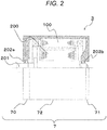
- FIG. 2 is a cross-sectional view illustrating the rotating electric machine 3 illustrated in FIG. 1 in a simplified manner, in which an upper area above a shaft 201 is illustrated in cross section and a lower area below the shaft 201 is illustrated in side view.
- the rotating electric machine 3 is accommodated inside a case 7 constituted by a front bracket 70, a rear bracket 71, and a housing 72.
- the case 7 is typically an integrated case constituted by the front bracket 70 and the housing 72 or an integrated case constituted by the rear bracket 71 and the housing 72.
- the case 7 is constituted by a case of the engine 2 or a case of the transmission 4.
- the rotating electric machine 3 may alternatively be mounted inside the transmission 4, and the case 7 may be constituted by the case of the transmission 4.
- the rotating electric machine 3 includes a stator 100 and a rotor 200.
- An outer side of the stator 100 is fixed to an inner side of the housing 72.
- the rotor 200 is disposed on an inner side of the stator 100 with a slight clearance therebetween.
- the rotor 200 is fixed to the shaft 201, which is a rotating shaft, and rotates integrally with the shaft 201.
- the shaft 201 has respective ends rotatably supported by the front bracket 70 and the rear bracket 71 with bearings 202a and 202b, respectively.
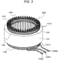
- FIG. 3 is an external perspective view of the stator of the rotating electric machine.
- the stator 100 includes a stator core 101 having a plurality of slots 105 arranged in the circumferential direction, and a stator winding 103 having coil conductors 102a to 102f (see FIG. 4 ) .
- the slots 105 are arranged at regular intervals with a predetermined pitch in an inner surface of the stator core 101.
- the respective slots 105 is formed through the stator core 101 from first end face 101a to second end face 101b of the stator core 101. Slits 108 through which the respective slots 105 communicate with an inner space of the stator core 101 are formed in the inner surface of the stator core 101.
- the stator core 101 is made of a laminated steel sheet that is a laminate of electromagnetic steel sheets.
- the stator winding 103 is a three-phase winding with wiring ends connected in star connection. Three-phase alternating currents of U, V, and W phases flow through the stator winding 103, and the rotating electric machine 3 operates as a motor or a generator/motor.
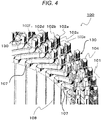
- FIG. 4 is an enlarged perspective view illustrating the vicinity of a joint part of the stator winding of the rotating electric machine illustrated in FIG. 3 .
- the stator winding 103 is formed by connecting a plurality of segment coil conductors 102a to 102f of the respective phases having a U-shape in their entirety.
- the segment coil conductors each have a pair of straight legs having ends represented by a reference numeral 130 in FIG. 4 , and lead-out terminals 106U, 106V, and 106W of the respective phases are connected by connecting wires to a conductor lead-out part 106 connecting the pair of straight legs in a U-shape as illustrated in FIG. 3 .
- the coil conductors 102a to 102f are made of conductive metal such as copper.
- the pair of legs of each of the coil conductors 102a to 102f having a U-shape are inserted in the slots 105 from the first end face 101a of the stator core 101 and protrude from the second end face 101b of the stator core 101.
- the pairs of legs of the respective segment coil conductors are inserted in different slots, and a set of ends 130 of the same phase protruding from different slots are welded as illustrated in FIG. 4 and forms a joint part 104 illustrated in FIG. 5 .
- the slots 105 are formed to have a long rectangular cross-sectional shape along the radial direction of the stator core 101.
- Six coil conductors 102a to 102f are arranged in the radial direction and inserted in each of the slots 105. Portions of the coil conductors 102a to 102f inserted into the slots 105 are wrapped by slot insulating paper 107 (see FIG. 4 ).
- the slot insulating paper 107 insulates the stator core 101 and the coil conductors 102a to 102f from each other.
- the slot insulating paper 107 insulates adjacent coil conductors 102a to 102f inserted in one slot 105 from each other.
- insulating layers such as varnish may be provided over the outer surfaces of the coil conductors 102a to 102f.
- the coil conductors 102a to 102f other than the ends 130 protruding from the second end face 101b of the stator core 101 are coated with insulating coating 131 such as enamel or varnish.
- the coil conductors 102a and 102b constitute a U-phase winding, for example, the coil conductors 102c and 102d constitute a V-phase winding, for example, and the coil conductors 102e and 102f constitute a W-phase winding, for example.
- the legs of coil conductors 102a to 102f are respectively welded and connected with the legs of other coil conductors 102a to 102f of the same phase, and form the stator winding 103 having an annular shape.
- FIG. 5 is an enlarged plan view of joint parts of coil conductors illustrated in FIG. 4 as viewed from end face sides of the coil conductors.
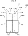
- FIG. 6 is an enlarged side view of the vicinity of ends of the coil conductors illustrated in FIG. 4 before being welded as viewed in a direction perpendicular to the radial direction of the stator core. Note that the direction perpendicular to the radial direction of the stator core refers to a direction in which a cross-section of an end 130 taken along line VI-VI in FIG. 5 illustrating a state after welding is viewed.
- the coil conductors 102a to 102f are members called rectangular wires having a substantially rectangular cross-sectional shape.
- a structure of a joint part 104 of coil conductors will be described with reference to a joint part 104a of the coil conductors 102a and 102b as an example.
- the leg of a U-phase coil conductor 102a is located at a backmost position of a slot of the stator core 101, protrudes from the first end face 101a of the stator core and is bent in the circumferential direction as illustrated in FIG. 4 .
- the leg of a U-phase coil conductor 102b is located on an inner side of the backmost position of the slot of stator core 101, protrudes from the first end face 101a of the stator core and is bent in the circumferential direction.
- the coil conductor 102b is located on the inner side of the coil conductor 102a at the backmost position in the slot.
- the insulating coating 131 is removed from each of the ends 130 of the coil conductors 102a and 102b.
- the end 130 of the coil conductor 102a has a flat end face 121a on the inner side of the stator core, and a weir portion 122a with a rising slope from the end face 121a on the outer side of the stator core.
- the end 130 of the coil conductor 102b has a flat end face 121b on the outer side of the stator core, and a weir portion 122b with a rising slope from the end face 121b on the inner side of the stator core.
- a pair of coil conductors 102a and 102b that are welded with each other are formed such that the coil conductor 102a on the outer side of the stator core has the weir portion 122a formed along a long side on the outer side of the stator, and that the coil conductor 102b on the inner side of the stator core has the weir portion 122b formed along a long side on the inner side of the stator.
- the ends 130 of coil conductors 102c and 102d and the ends 130 of coil conductors 102e and 102f also have end faces 121a to 121f and weir portion 122c to 122f, respectively.
- the weir portion 122a to 122f protruding in the axial direction from the end face 121a to 121f are formed at the ends 130 of the coil conductors 120a to 120f.
- a side face 121s of the coil conductor 102a facing the inner side of the stator core and a side face 121s of the end face 121b of the coil conductor 102b facing the outer side of the stator core are arranged to be in surface contact with each other.
- the weir portion 122a and the weir portion 122b are opposed to each other and form a pool space WS of molten metal is formed in a valley therebetween.
- the bottom of the pool space WS is constituted by the flat end faces 121a and 121b.
- the coil conductors 102a and 102b are joined by tungsten inert gas (TIG) welding or TIG brazing.
- TIG tungsten inert gas
- the coil conductors 102a and 102b are welded on the end faces 121a and 121b of the coil conductors 102a and 102b, and joined by a jointing material 110 obtained by solidification of molten metal in the pool space WS (see FIG. 6 ).
- the jointing material 110 obtained by solidification of molten metal is formed to stick out from side faces of the end faces 121 of the coil conductors 102a and 102b in the circumferential direction. In the radial direction of the stator core, however, molten metal is blocked by the weir portions 122a and 122b of the coil conductors 102a and 102b.
- molten metal does not leak to the outer side of the weir portion 122a of the coil conductor 102a and the inner side of the weir portion 122b of the coil conductor 102b during welding.
- the jointing material 110 does not stick out to the outer side nor to the inner side in the radial direction of the stator core.
- a joint part 104b of the coil conductors 102c and 102d and a joint part 104c of the coil conductors 102e and 102f are the same as that of the joint part 104a.
- the weir portions 122c and 122d formed on the coil conductors 102c and 102d, respectively prevent molten metal from flowing in the radial direction of the stator core 101 during welding.
- the weir portions 122e and 122f formed on the coil conductors 102e and 102f respectively, prevent molten metal from flowing in the radial direction of the stator core 101 during welding.
- the jointing material 110 does not stick out to the outer side nor to the inner side in the radial direction of the stator core at the joint part 104b of the coil conductors 102c and 102d and the joint part 104c of the coil conductors 102e and 102f as well.
- the joint part 104a is located on the outermost side of the stator core 101
- the joint part 104c is located on the innermost side of the stator core 101
- the joint part 104b is located between the joint part 104a and the joint part 104c.
- the joint part 104a to 104c are arranged adjacent to one another in the radial direction of the stator core 101.
- the weir portion 122a to 122f formed on the coil conductors 102a to 103f blocks the jointing material 110 from flowing to adjacent joint parts 104 in the radial direction of the stator core 101 during welding. This prevents short circuit of the stator winding 103 due to the jointing material 110.
- the coil conductors 102a to 102f and the weir portion 122a to 122b will be referred to as coil conductors 102 and weir portions 122, respectively.
- the flat end faces 121 joined by the jointing material 110 and the weir portions 122 protruding in the axial direction from the end faces 121 are formed on the respective ends 130 of the coil conductors 102.
- the flow of molten metal for welding is blocked by the weir portions 122, and the jointing material 110 will not become a large block in a drop-like ball shape. This prevents short circuit of adjacent portions of stator winding 103.
- FIG. 7 is an enlarged perspective view illustrating a second embodiment of the invention, and illustrates the vicinity of a joint part of a stator of a rotating electric machine.
- FIG. 8 is an enlarged plan view of the vicinity of ends of coil conductors illustrated in FIG. 7 as viewed from end face sides of the coil conductors
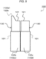
- FIG. 9 is an enlarged side view illustrating the vicinity of an end before welding of an outermost or innermost coil conductor illustrated in FIG. 7 as viewed in a direction perpendicular to a radial direction of a stator core.
- weir portions 122a and 122f are not formed on the outermost coil conductor 102a and the innermost coil conductor 102f. As illustrated in FIG.
- the entire end face 121 of the end 130 of the outermost coil conductor 102a is formed to be flat.
- a weir portion 122b is formed on a side on the inner side of the end 130 of the coil conductor 102b adjacent to the inner side of the coil conductor 102a.
- the entire end face 121 of the end 130 of the innermost coil conductor 102f is formed to be flat, and a weir portion 122e is formed on a side on the outer side of the end 130 of the coil conductors 102e adjacent to the outer side of the coil conductor 102f.
- weir portions 122c and 122d are formed on a side on the outer side of the end 130 of the coil conductor 102c and on a side on the inner side of the end 130 of the coil conductor 102d, respectively.
- the jointing material 110 is thus blocked by the weir portions 122c and 122d, and does not stick out to the outer side of the weir portion 122c and the inner side of the weir portion 122d.
- the joint part 104b does not short-circuit to the joint part 104a on the outer side and the joint part 104c on the inner side.
- the jointing material 110 sticks out to the outer side of the coil conductor 102a.
- No coil conductor 102 constituting the stator winding 103 is, however, provided on the outer side of the joint part 104a.
- the jointing material 110 sticks out to the inner side of the coil conductor 102f.
- No coil conductor 102 constituting the stator winding 103 is, however, provided on the inner side of the joint part 104a.
- the stator winding 103 does not short-circuit due to the joint parts 104a and 104c.
- Other configuration of the second embodiment is similar to that in the first embodiment.
- the second embodiment also produces effects similar to the effects (1) to (4) of the first embodiment.
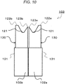
- FIG. 10 is an enlarged side view illustrating a third embodiment of the invention, and illustrates a structure before welding in the vicinity of ends of coil conductors as viewed in a direction perpendicular to a radial direction of a stator core.
- the third embodiment has a structure in which projections 123a and 123b having a smaller height than the weir portions 122a and 122b are formed on sides of a pair of joined coil conductors 102a and 102b on the side facing each other.
- the weir portion 122a is formed on a side on the outer side and the projection 123a is formed on a side on the inner side.
- a flat end face 121 is formed at the boundary between the weir portion 122a and the projection 122a.
- the weir portion 122b is formed on a side on the inner side and the projection 123b is formed on a side on the inner side.
- a flat end face 121 is formed at the boundary between the weir portion 122b and the projection 123b.
- the projections 123a and 123b have smaller heights and smaller bottom surface areas than the weir portions 122a and 122b. Thus, the projections 123a and 123b have smaller volumes than the weir portions 122a and 122b.
- the projection 123a and the projection 123b are arranged adjacent to each other in the radial direction at overlapping positions in the circumferential direction of the stator core 101.
- the weir portions 122a and 122b are arranged on the sides opposite to the sides where the projection 123a and the projection 123b face each other.
- the projections 123a and 123b are formed as portions of the coil conductors 102a and 102b to be actively melted during welding. Melting of the projections 123a and 123b mitigates thermal impact on the weir portions 122a and 122b. This improves the performance of blocking molten metal by the weir portions 122a and 122b.
- the third embodiment produces the effects (1) to (3) of the first embodiment.
- the blocking performance of the weir portion 122 is improved. Note that, similarly to the second embodiment, no weir portions 122a and 122f may be formed on the outermost coil conductor 102a and the innermost coil conductor 102f.
- FIG. 11 is a modification of the structure in the vicinity of the ends of the coil conductors illustrated in FIG. 10 .
- no flat end face 121 is formed at the upper portions of the ends 130 of the coil conductors 102a and 102b.
- the weir portions 122a and 122b and the projections 123a and 123b are formed at the upper portions of the ends 130 of the coil conductors 102a and 102b.
- No flat end faces 121 are formed at the boundaries of the weir portions 122a and 122b and the projections 123a and 123b.
- Such a structure also produces effects similar to those of the third embodiment.
- the structure in which six coil conductors 102 are inserted in one slot 105 has been presented as an example.
- the invention is not limited thereto, and can be applied to any stator 100 in which the number of coil conductors 102 inserted in one slot 105 is four or more.
- the coil conductors 102 have been presented as members called rectangular wires having a substantially rectangular cross-sectional shape.
- the coil conductors 102 may be round wires.
- a rotating electric machine includes a rotor, and a stator having a stator core and a stator winding.
- the stator winding has a plurality of coil conductors, and joint parts connecting ends of the coil conductors protruding from an end face of the stator core, and weir portions (molten metal flow blocking weirs) for blocking flow of metal of the joint parts are formed at the ends of the coil conductors.
Landscapes
- Engineering & Computer Science (AREA)
- Power Engineering (AREA)
- Manufacturing & Machinery (AREA)
- Windings For Motors And Generators (AREA)
- Manufacture Of Motors, Generators (AREA)
Applications Claiming Priority (2)
| Application Number | Priority Date | Filing Date | Title |
|---|---|---|---|
| JP2015187578 | 2015-09-25 | ||
| PCT/JP2016/072572 WO2017051609A1 (fr) | 2015-09-25 | 2016-08-02 | Machine électrique rotative et son procédé de fabrication |
Publications (3)
| Publication Number | Publication Date |
|---|---|
| EP3355445A1 true EP3355445A1 (fr) | 2018-08-01 |
| EP3355445A4 EP3355445A4 (fr) | 2019-05-22 |
| EP3355445B1 EP3355445B1 (fr) | 2021-02-17 |
Family
ID=58386014
Family Applications (1)
| Application Number | Title | Priority Date | Filing Date |
|---|---|---|---|
| EP16848397.2A Active EP3355445B1 (fr) | 2015-09-25 | 2016-08-02 | Machine électrique rotative et son procédé de fabrication |
Country Status (5)
| Country | Link |
|---|---|
| US (1) | US10523073B2 (fr) |
| EP (1) | EP3355445B1 (fr) |
| JP (1) | JP6473824B2 (fr) |
| CN (1) | CN108141083B (fr) |
| WO (1) | WO2017051609A1 (fr) |
Families Citing this family (10)
| Publication number | Priority date | Publication date | Assignee | Title |
|---|---|---|---|---|
| EP3355445B1 (fr) * | 2015-09-25 | 2021-02-17 | Hitachi Automotive Systems, Ltd. | Machine électrique rotative et son procédé de fabrication |
| JP6642123B2 (ja) * | 2016-03-04 | 2020-02-05 | 株式会社デンソー | 回転電機 |
| DE102017200688A1 (de) * | 2016-07-08 | 2018-01-11 | Robert Bosch Gmbh | Stator einer elektrischen Maschine |
| JP6752323B1 (ja) * | 2019-04-10 | 2020-09-09 | 三菱電機株式会社 | 回転電機の固定子巻線およびその製造方法 |
| JP6873191B2 (ja) * | 2019-06-19 | 2021-05-19 | 三菱電機株式会社 | 固定子およびこの固定子を備えた回転電機 |
| DE102019119666A1 (de) | 2019-07-19 | 2021-01-21 | Gehring E-Tech Gmbh | Verfahren zum Verschweißen von Leiterstücken in einer Komponente eines elektromechanischen Wandlers sowie Komponente eines elektromechanischen Wandlers mit verschweißten Leiterstücken |
| WO2021048994A1 (fr) * | 2019-09-12 | 2021-03-18 | 株式会社 東芝 | Stator et procédé de fabrication de stator |
| DE112020004995T5 (de) * | 2019-11-20 | 2022-06-30 | Hitachi Astemo, Ltd. | Verfahren zum herstellen des stators einer rotierenden elektrischen maschine, stator einer rotierenden elektrischen maschine und rotierende elektrische maschine |
| JP7660016B2 (ja) * | 2021-04-02 | 2025-04-10 | 株式会社プロテリアル | 溶接方法、及び回転電機の製造方法 |
| KR20240093940A (ko) * | 2021-10-26 | 2024-06-24 | 어탑 에스.피.에이. | 유도 권선 등의 전기 케이블들의 단부에 대한 커플링 방법 |
Family Cites Families (19)
| Publication number | Priority date | Publication date | Assignee | Title |
|---|---|---|---|---|
| JPS5746641A (en) * | 1980-09-03 | 1982-03-17 | Matsushita Electric Works Ltd | Iron-coreless armature |
| US6181043B1 (en) * | 1997-12-10 | 2001-01-30 | Denso Corporation | Alternator for vehicle |
| JP3475818B2 (ja) * | 1998-02-19 | 2003-12-10 | 株式会社デンソー | 回転電機の電機子及び電機子の製造方法 |
| JP2002119003A (ja) * | 2000-10-10 | 2002-04-19 | Mitsubishi Electric Corp | 回転電機の固定子とその製造方法 |
| FR2821498B1 (fr) * | 2001-02-28 | 2004-01-16 | Valeo Equip Electr Moteur | Procede d'assemblage de segments conducteurs d'un bobinage de rotor ou de stator de machine electrique rotative |
| JP3709823B2 (ja) | 2001-10-05 | 2005-10-26 | 株式会社デンソー | 車両用交流発電機 |
| JP3786059B2 (ja) * | 2002-06-25 | 2006-06-14 | 株式会社デンソー | 回転電機のセグメント順次接合ステータコイルおよびその製造方法 |
| JP4654068B2 (ja) * | 2005-05-24 | 2011-03-16 | 日立オートモティブシステムズ株式会社 | 接合電線と接合電線の加工方法,回転電機の固定子と回転電機の固定子の製造方法及び接合電線製造装置 |
| DE102006019314A1 (de) * | 2006-04-26 | 2007-10-31 | Robert Bosch Gmbh | Verfahren und Vorrichtung zur Herstellung einer Stabwicklung für den Stator einer elektrischen Maschine |
| JP5565381B2 (ja) * | 2011-06-17 | 2014-08-06 | 株式会社デンソー | 回転電機の固定子 |
| US20130106231A1 (en) * | 2011-10-27 | 2013-05-02 | Remy Technologies, L.L.C. | Conductor weld-end length control forming |
| JP5585657B2 (ja) * | 2011-12-28 | 2014-09-10 | トヨタ自動車株式会社 | 回転電機及び固定子製造方法 |
| US8443509B1 (en) * | 2012-04-18 | 2013-05-21 | GM Global Technology Operations LLC | Preparing bar-wound stator conductors for electrical interconnection |
| JP5958109B2 (ja) * | 2012-06-21 | 2016-07-27 | アイシン・エィ・ダブリュ株式会社 | 回転電機の導体接合方法 |
| JP5935587B2 (ja) * | 2012-08-10 | 2016-06-15 | 株式会社デンソー | マルチギャップ型回転電機 |
| US20150214820A1 (en) * | 2014-01-24 | 2015-07-30 | Remy Technologies, Llc | Hairpin joint |
| US11088583B2 (en) * | 2014-12-26 | 2021-08-10 | Hitachi Automotive Systems, Ltd. | Rotary-electric-machine stator coil, rotary-electric-machine stator having the same, and rotary electric machine having the same |
| EP3355445B1 (fr) * | 2015-09-25 | 2021-02-17 | Hitachi Automotive Systems, Ltd. | Machine électrique rotative et son procédé de fabrication |
| JP6642123B2 (ja) * | 2016-03-04 | 2020-02-05 | 株式会社デンソー | 回転電機 |
-
2016
- 2016-08-02 EP EP16848397.2A patent/EP3355445B1/fr active Active
- 2016-08-02 US US15/755,226 patent/US10523073B2/en active Active
- 2016-08-02 WO PCT/JP2016/072572 patent/WO2017051609A1/fr not_active Ceased
- 2016-08-02 CN CN201680036179.3A patent/CN108141083B/zh active Active
- 2016-08-02 JP JP2017541462A patent/JP6473824B2/ja active Active
Also Published As
| Publication number | Publication date |
|---|---|
| US10523073B2 (en) | 2019-12-31 |
| US20180248430A1 (en) | 2018-08-30 |
| WO2017051609A1 (fr) | 2017-03-30 |
| EP3355445A4 (fr) | 2019-05-22 |
| EP3355445B1 (fr) | 2021-02-17 |
| CN108141083A (zh) | 2018-06-08 |
| CN108141083B (zh) | 2020-04-21 |
| JP6473824B2 (ja) | 2019-02-20 |
| JPWO2017051609A1 (ja) | 2018-03-01 |
Similar Documents
| Publication | Publication Date | Title |
|---|---|---|
| EP3355445B1 (fr) | Machine électrique rotative et son procédé de fabrication | |
| EP3240147B1 (fr) | Méthode de fabrication d'une bobine de stator de machine électrique rotative | |
| JP5541585B2 (ja) | 回転電機 | |
| EP3214732B1 (fr) | Stator pour machine électrique rotative | |
| CN111463942A (zh) | 旋转电机 | |
| JP6159819B2 (ja) | 固定子及びこれを備えた回転電機 | |
| US9847684B2 (en) | Stator and rotating electric machine | |
| JP6777760B2 (ja) | 回転電機用の固定子、及び回転電機 | |
| CN110771013A (zh) | 旋转电机的定子以及旋转电机 | |
| US8659201B2 (en) | Stator for electric rotating machine | |
| US11594930B2 (en) | Rotating electric machine | |
| JP4662141B2 (ja) | 固定子を含む回転電機 | |
| JP7776983B2 (ja) | ステータおよびその製造方法 | |
| JP2009044780A (ja) | 回転電機の渡り導体接合型ステータコイル | |
| JP5647285B2 (ja) | 固定子巻線、固定子および回転電機 | |
| EP4057483B1 (fr) | Stator pour moteur et moteur le comprenant | |
| JP2019118249A (ja) | 固定子および電動機 | |
| US20220037945A1 (en) | Rotary electric machine stator | |
| US20260088675A1 (en) | Stator | |
| JP2023011457A (ja) | 電動機 | |
| WO2025205332A1 (fr) | Stator | |
| JP2021151170A (ja) | 車両用回転電機のステータ |
Legal Events
| Date | Code | Title | Description |
|---|---|---|---|
| STAA | Information on the status of an ep patent application or granted ep patent |
Free format text: STATUS: THE INTERNATIONAL PUBLICATION HAS BEEN MADE |
|
| PUAI | Public reference made under article 153(3) epc to a published international application that has entered the european phase |
Free format text: ORIGINAL CODE: 0009012 |
|
| STAA | Information on the status of an ep patent application or granted ep patent |
Free format text: STATUS: REQUEST FOR EXAMINATION WAS MADE |
|
| 17P | Request for examination filed |
Effective date: 20180228 |
|
| AK | Designated contracting states |
Kind code of ref document: A1 Designated state(s): AL AT BE BG CH CY CZ DE DK EE ES FI FR GB GR HR HU IE IS IT LI LT LU LV MC MK MT NL NO PL PT RO RS SE SI SK SM TR |
|
| AX | Request for extension of the european patent |
Extension state: BA ME |
|
| DAV | Request for validation of the european patent (deleted) | ||
| DAX | Request for extension of the european patent (deleted) | ||
| A4 | Supplementary search report drawn up and despatched |
Effective date: 20190424 |
|
| RIC1 | Information provided on ipc code assigned before grant |
Ipc: H02K 3/34 20060101ALN20190416BHEP Ipc: H02K 3/12 20060101ALI20190416BHEP Ipc: H02K 15/04 20060101AFI20190416BHEP Ipc: H02K 15/00 20060101ALI20190416BHEP |
|
| STAA | Information on the status of an ep patent application or granted ep patent |
Free format text: STATUS: EXAMINATION IS IN PROGRESS |
|
| 17Q | First examination report despatched |
Effective date: 20200623 |
|
| REG | Reference to a national code |
Ref country code: DE Ref legal event code: R079 Ref document number: 602016052794 Country of ref document: DE Free format text: PREVIOUS MAIN CLASS: H02K0003040000 Ipc: H02K0015040000 |
|
| RIC1 | Information provided on ipc code assigned before grant |
Ipc: H02K 15/00 20060101ALI20200908BHEP Ipc: H02K 3/12 20060101ALI20200908BHEP Ipc: H02K 3/34 20060101ALN20200908BHEP Ipc: H02K 15/04 20060101AFI20200908BHEP |
|
| GRAP | Despatch of communication of intention to grant a patent |
Free format text: ORIGINAL CODE: EPIDOSNIGR1 |
|
| STAA | Information on the status of an ep patent application or granted ep patent |
Free format text: STATUS: GRANT OF PATENT IS INTENDED |
|
| INTG | Intention to grant announced |
Effective date: 20201019 |
|
| GRAS | Grant fee paid |
Free format text: ORIGINAL CODE: EPIDOSNIGR3 |
|
| GRAA | (expected) grant |
Free format text: ORIGINAL CODE: 0009210 |
|
| STAA | Information on the status of an ep patent application or granted ep patent |
Free format text: STATUS: THE PATENT HAS BEEN GRANTED |
|
| AK | Designated contracting states |
Kind code of ref document: B1 Designated state(s): AL AT BE BG CH CY CZ DE DK EE ES FI FR GB GR HR HU IE IS IT LI LT LU LV MC MK MT NL NO PL PT RO RS SE SI SK SM TR |
|
| REG | Reference to a national code |
Ref country code: GB Ref legal event code: FG4D |
|
| REG | Reference to a national code |
Ref country code: CH Ref legal event code: EP |
|
| REG | Reference to a national code |
Ref country code: DE Ref legal event code: R096 Ref document number: 602016052794 Country of ref document: DE |
|
| REG | Reference to a national code |
Ref country code: AT Ref legal event code: REF Ref document number: 1362793 Country of ref document: AT Kind code of ref document: T Effective date: 20210315 |
|
| REG | Reference to a national code |
Ref country code: IE Ref legal event code: FG4D |
|
| REG | Reference to a national code |
Ref country code: LT Ref legal event code: MG9D |
|
| REG | Reference to a national code |
Ref country code: NL Ref legal event code: MP Effective date: 20210217 |
|
| PG25 | Lapsed in a contracting state [announced via postgrant information from national office to epo] |
Ref country code: NO Free format text: LAPSE BECAUSE OF FAILURE TO SUBMIT A TRANSLATION OF THE DESCRIPTION OR TO PAY THE FEE WITHIN THE PRESCRIBED TIME-LIMIT Effective date: 20210517 Ref country code: PT Free format text: LAPSE BECAUSE OF FAILURE TO SUBMIT A TRANSLATION OF THE DESCRIPTION OR TO PAY THE FEE WITHIN THE PRESCRIBED TIME-LIMIT Effective date: 20210617 Ref country code: HR Free format text: LAPSE BECAUSE OF FAILURE TO SUBMIT A TRANSLATION OF THE DESCRIPTION OR TO PAY THE FEE WITHIN THE PRESCRIBED TIME-LIMIT Effective date: 20210217 Ref country code: FI Free format text: LAPSE BECAUSE OF FAILURE TO SUBMIT A TRANSLATION OF THE DESCRIPTION OR TO PAY THE FEE WITHIN THE PRESCRIBED TIME-LIMIT Effective date: 20210217 Ref country code: GR Free format text: LAPSE BECAUSE OF FAILURE TO SUBMIT A TRANSLATION OF THE DESCRIPTION OR TO PAY THE FEE WITHIN THE PRESCRIBED TIME-LIMIT Effective date: 20210518 Ref country code: BG Free format text: LAPSE BECAUSE OF FAILURE TO SUBMIT A TRANSLATION OF THE DESCRIPTION OR TO PAY THE FEE WITHIN THE PRESCRIBED TIME-LIMIT Effective date: 20210517 Ref country code: LT Free format text: LAPSE BECAUSE OF FAILURE TO SUBMIT A TRANSLATION OF THE DESCRIPTION OR TO PAY THE FEE WITHIN THE PRESCRIBED TIME-LIMIT Effective date: 20210217 |
|
| REG | Reference to a national code |
Ref country code: AT Ref legal event code: MK05 Ref document number: 1362793 Country of ref document: AT Kind code of ref document: T Effective date: 20210217 |
|
| PG25 | Lapsed in a contracting state [announced via postgrant information from national office to epo] |
Ref country code: PL Free format text: LAPSE BECAUSE OF FAILURE TO SUBMIT A TRANSLATION OF THE DESCRIPTION OR TO PAY THE FEE WITHIN THE PRESCRIBED TIME-LIMIT Effective date: 20210217 Ref country code: LV Free format text: LAPSE BECAUSE OF FAILURE TO SUBMIT A TRANSLATION OF THE DESCRIPTION OR TO PAY THE FEE WITHIN THE PRESCRIBED TIME-LIMIT Effective date: 20210217 Ref country code: RS Free format text: LAPSE BECAUSE OF FAILURE TO SUBMIT A TRANSLATION OF THE DESCRIPTION OR TO PAY THE FEE WITHIN THE PRESCRIBED TIME-LIMIT Effective date: 20210217 Ref country code: NL Free format text: LAPSE BECAUSE OF FAILURE TO SUBMIT A TRANSLATION OF THE DESCRIPTION OR TO PAY THE FEE WITHIN THE PRESCRIBED TIME-LIMIT Effective date: 20210217 Ref country code: SE Free format text: LAPSE BECAUSE OF FAILURE TO SUBMIT A TRANSLATION OF THE DESCRIPTION OR TO PAY THE FEE WITHIN THE PRESCRIBED TIME-LIMIT Effective date: 20210217 |
|
| PG25 | Lapsed in a contracting state [announced via postgrant information from national office to epo] |
Ref country code: IS Free format text: LAPSE BECAUSE OF FAILURE TO SUBMIT A TRANSLATION OF THE DESCRIPTION OR TO PAY THE FEE WITHIN THE PRESCRIBED TIME-LIMIT Effective date: 20210617 |
|
| REG | Reference to a national code |
Ref country code: DE Ref legal event code: R081 Ref document number: 602016052794 Country of ref document: DE Owner name: HITACHI ASTEMO, LTD., HITACHINAKA-SHI, JP Free format text: FORMER OWNER: HITACHI AUTOMOTIVE SYSTEMS, LTD., HITACHINAKA-SHI, IBARAKI, JP |
|
| PG25 | Lapsed in a contracting state [announced via postgrant information from national office to epo] |
Ref country code: CZ Free format text: LAPSE BECAUSE OF FAILURE TO SUBMIT A TRANSLATION OF THE DESCRIPTION OR TO PAY THE FEE WITHIN THE PRESCRIBED TIME-LIMIT Effective date: 20210217 Ref country code: EE Free format text: LAPSE BECAUSE OF FAILURE TO SUBMIT A TRANSLATION OF THE DESCRIPTION OR TO PAY THE FEE WITHIN THE PRESCRIBED TIME-LIMIT Effective date: 20210217 Ref country code: SM Free format text: LAPSE BECAUSE OF FAILURE TO SUBMIT A TRANSLATION OF THE DESCRIPTION OR TO PAY THE FEE WITHIN THE PRESCRIBED TIME-LIMIT Effective date: 20210217 Ref country code: AT Free format text: LAPSE BECAUSE OF FAILURE TO SUBMIT A TRANSLATION OF THE DESCRIPTION OR TO PAY THE FEE WITHIN THE PRESCRIBED TIME-LIMIT Effective date: 20210217 |
|
| REG | Reference to a national code |
Ref country code: DE Ref legal event code: R097 Ref document number: 602016052794 Country of ref document: DE |
|
| PG25 | Lapsed in a contracting state [announced via postgrant information from national office to epo] |
Ref country code: DK Free format text: LAPSE BECAUSE OF FAILURE TO SUBMIT A TRANSLATION OF THE DESCRIPTION OR TO PAY THE FEE WITHIN THE PRESCRIBED TIME-LIMIT Effective date: 20210217 Ref country code: SK Free format text: LAPSE BECAUSE OF FAILURE TO SUBMIT A TRANSLATION OF THE DESCRIPTION OR TO PAY THE FEE WITHIN THE PRESCRIBED TIME-LIMIT Effective date: 20210217 Ref country code: RO Free format text: LAPSE BECAUSE OF FAILURE TO SUBMIT A TRANSLATION OF THE DESCRIPTION OR TO PAY THE FEE WITHIN THE PRESCRIBED TIME-LIMIT Effective date: 20210217 |
|
| PLBE | No opposition filed within time limit |
Free format text: ORIGINAL CODE: 0009261 |
|
| STAA | Information on the status of an ep patent application or granted ep patent |
Free format text: STATUS: NO OPPOSITION FILED WITHIN TIME LIMIT |
|
| 26N | No opposition filed |
Effective date: 20211118 |
|
| PG25 | Lapsed in a contracting state [announced via postgrant information from national office to epo] |
Ref country code: ES Free format text: LAPSE BECAUSE OF FAILURE TO SUBMIT A TRANSLATION OF THE DESCRIPTION OR TO PAY THE FEE WITHIN THE PRESCRIBED TIME-LIMIT Effective date: 20210217 Ref country code: AL Free format text: LAPSE BECAUSE OF FAILURE TO SUBMIT A TRANSLATION OF THE DESCRIPTION OR TO PAY THE FEE WITHIN THE PRESCRIBED TIME-LIMIT Effective date: 20210217 |
|
| PG25 | Lapsed in a contracting state [announced via postgrant information from national office to epo] |
Ref country code: SI Free format text: LAPSE BECAUSE OF FAILURE TO SUBMIT A TRANSLATION OF THE DESCRIPTION OR TO PAY THE FEE WITHIN THE PRESCRIBED TIME-LIMIT Effective date: 20210217 |
|
| REG | Reference to a national code |
Ref country code: CH Ref legal event code: PL |
|
| PG25 | Lapsed in a contracting state [announced via postgrant information from national office to epo] |
Ref country code: MC Free format text: LAPSE BECAUSE OF FAILURE TO SUBMIT A TRANSLATION OF THE DESCRIPTION OR TO PAY THE FEE WITHIN THE PRESCRIBED TIME-LIMIT Effective date: 20210217 |
|
| REG | Reference to a national code |
Ref country code: BE Ref legal event code: MM Effective date: 20210831 |
|
| GBPC | Gb: european patent ceased through non-payment of renewal fee |
Effective date: 20210802 |
|
| PG25 | Lapsed in a contracting state [announced via postgrant information from national office to epo] |
Ref country code: LI Free format text: LAPSE BECAUSE OF NON-PAYMENT OF DUE FEES Effective date: 20210831 Ref country code: IT Free format text: LAPSE BECAUSE OF FAILURE TO SUBMIT A TRANSLATION OF THE DESCRIPTION OR TO PAY THE FEE WITHIN THE PRESCRIBED TIME-LIMIT Effective date: 20210217 Ref country code: CH Free format text: LAPSE BECAUSE OF NON-PAYMENT OF DUE FEES Effective date: 20210831 |
|
| PG25 | Lapsed in a contracting state [announced via postgrant information from national office to epo] |
Ref country code: IS Free format text: LAPSE BECAUSE OF FAILURE TO SUBMIT A TRANSLATION OF THE DESCRIPTION OR TO PAY THE FEE WITHIN THE PRESCRIBED TIME-LIMIT Effective date: 20210617 Ref country code: LU Free format text: LAPSE BECAUSE OF NON-PAYMENT OF DUE FEES Effective date: 20210802 |
|
| PG25 | Lapsed in a contracting state [announced via postgrant information from national office to epo] |
Ref country code: IE Free format text: LAPSE BECAUSE OF NON-PAYMENT OF DUE FEES Effective date: 20210802 Ref country code: GB Free format text: LAPSE BECAUSE OF NON-PAYMENT OF DUE FEES Effective date: 20210802 Ref country code: FR Free format text: LAPSE BECAUSE OF NON-PAYMENT OF DUE FEES Effective date: 20210831 Ref country code: BE Free format text: LAPSE BECAUSE OF NON-PAYMENT OF DUE FEES Effective date: 20210831 |
|
| PG25 | Lapsed in a contracting state [announced via postgrant information from national office to epo] |
Ref country code: HU Free format text: LAPSE BECAUSE OF FAILURE TO SUBMIT A TRANSLATION OF THE DESCRIPTION OR TO PAY THE FEE WITHIN THE PRESCRIBED TIME-LIMIT; INVALID AB INITIO Effective date: 20160802 |
|
| PG25 | Lapsed in a contracting state [announced via postgrant information from national office to epo] |
Ref country code: CY Free format text: LAPSE BECAUSE OF FAILURE TO SUBMIT A TRANSLATION OF THE DESCRIPTION OR TO PAY THE FEE WITHIN THE PRESCRIBED TIME-LIMIT Effective date: 20210217 |
|
| PG25 | Lapsed in a contracting state [announced via postgrant information from national office to epo] |
Ref country code: MK Free format text: LAPSE BECAUSE OF FAILURE TO SUBMIT A TRANSLATION OF THE DESCRIPTION OR TO PAY THE FEE WITHIN THE PRESCRIBED TIME-LIMIT Effective date: 20210217 |
|
| PG25 | Lapsed in a contracting state [announced via postgrant information from national office to epo] |
Ref country code: MT Free format text: LAPSE BECAUSE OF FAILURE TO SUBMIT A TRANSLATION OF THE DESCRIPTION OR TO PAY THE FEE WITHIN THE PRESCRIBED TIME-LIMIT Effective date: 20210217 |
|
| PGFP | Annual fee paid to national office [announced via postgrant information from national office to epo] |
Ref country code: DE Payment date: 20250702 Year of fee payment: 10 |
|
| PG25 | Lapsed in a contracting state [announced via postgrant information from national office to epo] |
Ref country code: TR Free format text: LAPSE BECAUSE OF FAILURE TO SUBMIT A TRANSLATION OF THE DESCRIPTION OR TO PAY THE FEE WITHIN THE PRESCRIBED TIME-LIMIT Effective date: 20210217 |