EP3355651A1 - Procédé et dispositif permettant à une station de base de prendre en charge le partage de réseau ran - Google Patents
Procédé et dispositif permettant à une station de base de prendre en charge le partage de réseau ran Download PDFInfo
- Publication number
- EP3355651A1 EP3355651A1 EP16848847.6A EP16848847A EP3355651A1 EP 3355651 A1 EP3355651 A1 EP 3355651A1 EP 16848847 A EP16848847 A EP 16848847A EP 3355651 A1 EP3355651 A1 EP 3355651A1
- Authority
- EP
- European Patent Office
- Prior art keywords
- plmn
- wlan
- request message
- enb
- serving
- Prior art date
- Legal status (The legal status is an assumption and is not a legal conclusion. Google has not performed a legal analysis and makes no representation as to the accuracy of the status listed.)
- Withdrawn
Links
- 238000000034 method Methods 0.000 title claims abstract description 81
- 238000004891 communication Methods 0.000 claims abstract description 23
- 230000004048 modification Effects 0.000 claims description 58
- 238000012986 modification Methods 0.000 claims description 58
- 230000004044 response Effects 0.000 claims description 22
- 230000002776 aggregation Effects 0.000 claims description 9
- 238000004220 aggregation Methods 0.000 claims description 9
- 230000008878 coupling Effects 0.000 claims description 2
- 238000010168 coupling process Methods 0.000 claims description 2
- 238000005859 coupling reaction Methods 0.000 claims description 2
- 230000006870 function Effects 0.000 description 31
- 238000002360 preparation method Methods 0.000 description 27
- 230000005540 biological transmission Effects 0.000 description 15
- 238000007726 management method Methods 0.000 description 14
- 230000011664 signaling Effects 0.000 description 9
- 238000012546 transfer Methods 0.000 description 7
- 238000010586 diagram Methods 0.000 description 6
- 238000005516 engineering process Methods 0.000 description 5
- 230000008569 process Effects 0.000 description 5
- 238000013468 resource allocation Methods 0.000 description 5
- 238000009826 distribution Methods 0.000 description 4
- 230000008859 change Effects 0.000 description 3
- 230000006835 compression Effects 0.000 description 3
- 238000007906 compression Methods 0.000 description 3
- GVVPGTZRZFNKDS-JXMROGBWSA-N geranyl diphosphate Chemical compound CC(C)=CCC\C(C)=C\CO[P@](O)(=O)OP(O)(O)=O GVVPGTZRZFNKDS-JXMROGBWSA-N 0.000 description 3
- 238000005259 measurement Methods 0.000 description 3
- 230000006978 adaptation Effects 0.000 description 2
- 238000007689 inspection Methods 0.000 description 2
- 230000007774 longterm Effects 0.000 description 2
- 238000013507 mapping Methods 0.000 description 2
- 238000010295 mobile communication Methods 0.000 description 2
- 238000012545 processing Methods 0.000 description 2
- 238000003860 storage Methods 0.000 description 2
- 230000007704 transition Effects 0.000 description 2
- 101100161473 Arabidopsis thaliana ABCB25 gene Proteins 0.000 description 1
- 101100096893 Mus musculus Sult2a1 gene Proteins 0.000 description 1
- 101150081243 STA1 gene Proteins 0.000 description 1
- 230000004913 activation Effects 0.000 description 1
- 230000000694 effects Effects 0.000 description 1
- 238000001914 filtration Methods 0.000 description 1
- 230000006872 improvement Effects 0.000 description 1
- 230000008054 signal transmission Effects 0.000 description 1
- 208000000649 small cell carcinoma Diseases 0.000 description 1
- 230000001360 synchronised effect Effects 0.000 description 1
- 238000012384 transportation and delivery Methods 0.000 description 1
Images


Classifications
-
- H—ELECTRICITY
- H04—ELECTRIC COMMUNICATION TECHNIQUE
- H04W—WIRELESS COMMUNICATION NETWORKS
- H04W76/00—Connection management
- H04W76/10—Connection setup
-
- H—ELECTRICITY
- H04—ELECTRIC COMMUNICATION TECHNIQUE
- H04W—WIRELESS COMMUNICATION NETWORKS
- H04W48/00—Access restriction; Network selection; Access point selection
- H04W48/18—Selecting a network or a communication service
-
- H—ELECTRICITY
- H04—ELECTRIC COMMUNICATION TECHNIQUE
- H04W—WIRELESS COMMUNICATION NETWORKS
- H04W92/00—Interfaces specially adapted for wireless communication networks
- H04W92/16—Interfaces between hierarchically similar devices
- H04W92/20—Interfaces between hierarchically similar devices between access points
-
- H—ELECTRICITY
- H04—ELECTRIC COMMUNICATION TECHNIQUE
- H04W—WIRELESS COMMUNICATION NETWORKS
- H04W36/00—Hand-off or reselection arrangements
- H04W36/0005—Control or signalling for completing the hand-off
- H04W36/0011—Control or signalling for completing the hand-off for data sessions of end-to-end connection
- H04W36/0022—Control or signalling for completing the hand-off for data sessions of end-to-end connection for transferring data sessions between adjacent core network technologies
-
- H—ELECTRICITY
- H04—ELECTRIC COMMUNICATION TECHNIQUE
- H04W—WIRELESS COMMUNICATION NETWORKS
- H04W48/00—Access restriction; Network selection; Access point selection
- H04W48/16—Discovering, processing access restriction or access information
-
- H—ELECTRICITY
- H04—ELECTRIC COMMUNICATION TECHNIQUE
- H04W—WIRELESS COMMUNICATION NETWORKS
- H04W84/00—Network topologies
- H04W84/02—Hierarchically pre-organised networks, e.g. paging networks, cellular networks, WLAN [Wireless Local Area Network] or WLL [Wireless Local Loop]
- H04W84/10—Small scale networks; Flat hierarchical networks
- H04W84/12—WLAN [Wireless Local Area Networks]
-
- H—ELECTRICITY
- H04—ELECTRIC COMMUNICATION TECHNIQUE
- H04W—WIRELESS COMMUNICATION NETWORKS
- H04W88/00—Devices specially adapted for wireless communication networks, e.g. terminals, base stations or access point devices
- H04W88/02—Terminal devices
- H04W88/06—Terminal devices adapted for operation in multiple networks or having at least two operational modes, e.g. multi-mode terminals
Definitions
- the present invention relates to a wireless communication system, and more particularly, to a method of supporting radio access network (RAN) sharing by a base station in the wireless communication system, and an apparatus supporting the method.
- RAN radio access network
- 3GPP (3rd Generation Partnership Project) LTE Long Term Evolution (Long Term Evolution) that is an advancement of UMTS (Universal Mobile Telecommunication System) is being introduced with 3GPP release 8.
- 3GPP LTE OFDMA (orthogonal frequency division multiple access) is used for downlink, and SC-FDMA (single carrier-frequency division multiple access) is used for uplink.
- the 3GPP LTE adopts MIMO (multiple input multiple output) having maximum four antennas.
- 3GPP LTE-A LTE-Advanced
- a wireless communication system may provide a service to a UE through a plurality of access networks.
- the UE may receive a service from a 3GPP access network such as a mobile wireless communication system. Further, the UE may receive the service from a non-3GPP access network such as WiMAX (Worldwide Interoperability for Microwave Access) or a WLAN (Wireless Local Area Network).
- a 3GPP access network such as a mobile wireless communication system.
- a non-3GPP access network such as WiMAX (Worldwide Interoperability for Microwave Access) or a WLAN (Wireless Local Area Network).
- the UE may establish connection with a 3GPP access network to receive the service. Meanwhile, when traffic overload is generated in a 3GPP access network, if traffic to be processed by the UE is processed by another access network, that is, the non-3GPP access network, the whole efficiency of the network may be improved.
- changeable process of the traffic through the 3GPP access network and/or the non-GPP access network refers to traffic steering so that the traffic is changeably processed through a 3GPP access network and/or a non-GPP access network.
- a policy for interworking of the 3GPP access network and/or the non-GPP access network such as ANDSF (Access Network Discovery and Selection Functions) may be configured in the UE.
- the above policy is managed independently from an interworking policy configured by the network.
- a radio access network is shared between different operators.
- each operator may desire to allocate a preferential radio resource to a customer of the operator.
- WLAN termination including a plurality of access points (APs) cannot know a specific operator providing a service to a terminal. Accordingly, there is a need to propose a procedure in which a base station provides the WT with a serving public land mobile network identity (PLMN ID) for LTE-WLAN aggregation (LWA).
- PLMN ID public land mobile network identity
- the base station may transmit a WT addition request message to a WT.
- the WT addition request message may include a serving PLMN ID.
- the base station may receive at least one PLMN ID from the WT.
- the at least one PLMN ID may be received through an Xw setup response message.
- the serving PLMN ID may be one PLMN ID selected from the at least one PLMN ID.
- the serving PLMN ID may be used by the WT to manage a radio resource of the WT.
- the serving PLMN ID may be used by the WT to allocate a resource for LWA.
- the base station may receive a WT addition request acknowledge message from the WT in response to the WT addition request message.
- the base station may transmit a WT modification request message to a WT.
- the WT modification request message may include a serving PLMN ID.
- the base station may receive at least one PLMN ID from the WT.
- the at least one PLMN ID may be received through an Xw setup response message.
- the serving PLMN ID may be one PLMN ID selected from the at least one PLMN ID.
- the WT modification request message may include the serving PLMN ID
- the serving PLMN ID is used by the WT to manage a radio resource of the WT.
- the serving PLMN ID may be used by the WT to allocate a resource for LWA.
- the base station may receive a WT modification request acknowledge message from the WT in response to the WT modification request message.
- a base station for supporting RAN sharing in a wireless communication system.
- the base station may include: a memory; a transceiver; and a processor coupling the memory and the transceiver.
- the processor may be configured to allow the transceiver to transmit a WT addition request message to a WT.
- the WT addition request message may include a serving PLMN ID.
- An operator may perform radio resource management in an RAN sharing environment.
- CDMA code division multiple access
- FDMA frequency division multiple access
- TDMA time division multiple access
- OFDMA orthogonal frequency division multiple access
- SC-FDMA single carrier frequency division multiple access
- the CDMA can be implemented with a radio technology such as universal terrestrial radio access (UTRA) or CDMA-2000.
- UTRA universal terrestrial radio access
- the TDMA can be implemented with a radio technology such as global system for mobile communications (GSM)/general packet ratio service (GPRS)/enhanced data rate for GSM evolution (EDGE).
- GSM global system for mobile communications
- GPRS general packet ratio service
- EDGE enhanced data rate for GSM evolution
- the OFDMA can be implemented with a radio technology such as institute of electrical and electronics engineers (IEEE) 802.11 (Wi-Fi), IEEE 802.16 (WiMAX), IEEE 802.20, evolved UTRA (E-UTRA), etc.
- IEEE 802.16m is evolved from IEEE 802.16e, and provides backward compatibility with a system based on the IEEE 802.16e.
- the UTRA is a part of a universal mobile telecommunication system (UMTS).
- 3rd generation partnership project (3GPP) long term evolution (LTE) is a part of an evolved UMTS (E-UMTS) using the E-UTRA.
- 3GPP LTE uses the OFDMA in a downlink and uses the SC-FDMA in an uplink.
- LTE-advanced (LTE-A) is an evolution of the LTE.
- FIG. 1 shows LTE system architecture.
- the communication network is widely deployed to provide a variety of communication services such as voice over internet protocol (VoIP) through IMS and packet data.
- VoIP voice over internet protocol
- the LTE system architecture includes one or more user equipment (UE; 10), an evolved-UMTS terrestrial radio access network (E-UTRAN) and an evolved packet core (EPC).
- the UE 10 refers to a communication equipment carried by a user.
- the UE 10 may be fixed or mobile, and may be referred to as another terminology, such as a mobile station (MS), a user terminal (UT), a subscriber station (SS), a wireless device, etc.
- MS mobile station
- UT user terminal
- SS subscriber station
- wireless device etc.
- the E-UTRAN includes one or more evolved node-B (eNB) 20, and a plurality of UEs may be located in one cell.
- the eNB 20 provides an end point of a control plane and a user plane to the UE 10.
- the eNB 20 is generally a fixed station that communicates with the UE 10 and may be referred to as another terminology, such as a base station (BS), a base transceiver system (BTS), an access point, etc.
- BS base station
- BTS base transceiver system
- One eNB 20 may be deployed per cell.
- a single cell is configured to have one of bandwidths selected from 1.25, 2.5, 5, 10, and 20 MHz, etc., and provides downlink or uplink transmission services to several UEs. In this case, different cells can be configured to provide different bandwidths.
- a downlink (DL) denotes communication from the eNB 20 to the UE
- an uplink (UL) denotes communication from the UE 10 to the eNB 20.
- a transmitter may be a part of the eNB 20, and a receiver may be a part of the UE 10.
- the transmitter may be a part of the UE 10, and the receiver may be a part of the eNB 20.
- the EPC includes a mobility management entity (MME) which is in charge of control plane functions, and a system architecture evolution (SAE) gateway (S-GW) which is in charge of user plane functions.
- MME mobility management entity
- SAE system architecture evolution gateway
- S-GW system architecture evolution gateway
- the MME/S-GW 30 may be positioned at the end of the network and connected to an external network.
- the MME has UE access information or UE capability information, and such information may be primarily used in UE mobility management.
- the S-GW is a gateway of which an endpoint is an E-UTRAN.
- the MME/S-GW 30 provides an end point of a session and mobility management function for the UE 10.
- the EPC may further include a packet data network (PDN) gateway (PDN-GW).
- PDN-GW is a gateway of which an endpoint is a PDN.
- the MME provides various functions including non-access stratum (NAS) signaling to eNBs 20, NAS signaling security, access stratum (AS) security control, Inter core network (CN) node signaling for mobility between 3GPP access networks, idle mode UE reachability (including control and execution of paging retransmission), tracking area list management (for UE in idle and active mode), P-GW and S-GW selection, MME selection for handovers with MME change, serving GPRS support node (SGSN) selection for handovers to 2G or 3G 3GPP access networks, roaming, authentication, bearer management functions including dedicated bearer establishment, support for public warning system (PWS) (which includes earthquake and tsunami warning system (ETWS) and commercial mobile alert system (CMAS)) message transmission.
- PWS public warning system
- ETWS earthquake and tsunami warning system
- CMAS commercial mobile alert system
- the S-GW host provides assorted functions including per-user based packet filtering (by e.g., deep packet inspection), lawful interception, UE Internet protocol (IP) address allocation, transport level packet marking in the DL, UL and DL service level charging, gating and rate enforcement, DL rate enforcement based on APN-AMBR.
- per-user based packet filtering by e.g., deep packet inspection
- IP Internet protocol
- transport level packet marking in the DL UL and DL service level charging
- gating and rate enforcement DL rate enforcement based on APN-AMBR.
- MME/S-GW 30 will be referred to herein simply as a "gateway,” but it is understood that this entity includes both the MME and S-GW.
- Interfaces for transmitting user traffic or control traffic may be used.
- the UE 10 and the eNB 20 are connected by means of a Uu interface.
- the eNBs 20 are interconnected by means of an X2 interface. Neighboring eNBs may have a meshed network structure that has the X2 interface.
- the eNBs 20 are connected to the EPC by means of an S1 interface.
- the eNBs 20 are connected to the MME by means of an S1-MME interface, and are connected to the S-GW by means of S1-U interface.
- the S1 interface supports a many-to-many relation between the eNB 20 and the MME/S-GW.
- the eNB 20 may perform functions of selection for gateway 30, routing toward the gateway 30 during a radio resource control (RRC) activation, scheduling and transmitting of paging messages, scheduling and transmitting of broadcast channel (BCH) information, dynamic allocation of resources to the UEs 10 in both UL and DL, configuration and provisioning of eNB measurements, radio bearer control, radio admission control (RAC), and connection mobility control in LTE_ACTIVE state.
- RRC radio resource control
- BCH broadcast channel
- gateway 30 may perform functions of paging origination, LTE_IDLE state management, ciphering of the user plane, SAE bearer control, and ciphering and integrity protection of NAS signaling.
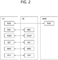
- FIG. 2 shows a control plane of a radio interface protocol of an LTE system.
- FIG. 3 shows a user plane of a radio interface protocol of an LTE system.
- Layers of a radio interface protocol between the UE and the E-UTRAN may be classified into a first layer (L1), a second layer (L2), and a third layer (L3) based on the lower three layers of the open system interconnection (OSI) model that is well-known in the communication system.
- the radio interface protocol between the UE and the E-UTRAN may be horizontally divided into a physical layer, a data link layer, and a network layer, and may be vertically divided into a control plane (C-plane) which is a protocol stack for control signal transmission and a user plane (U-plane) which is a protocol stack for data information transmission.
- C-plane control plane
- U-plane user plane
- the layers of the radio interface protocol exist in pairs at the UE and the E-UTRAN, and are in charge of data transmission of the Uu interface.
- a physical (PHY) layer belongs to the L1.
- the PHY layer provides a higher layer with an information transfer service through a physical channel.
- the PHY layer is connected to a medium access control (MAC) layer, which is a higher layer of the PHY layer, through a transport channel.
- MAC medium access control
- a physical channel is mapped to the transport channel.
- Data is transferred between the MAC layer and the PHY layer through the transport channel.
- the physical channel is modulated using an orthogonal frequency division multiplexing (OFDM) scheme, and utilizes time and frequency as a radio resource.
- OFDM orthogonal frequency division multiplexing
- the PHY layer uses several physical control channels.
- a physical downlink control channel (PDCCH) reports to a UE about resource allocation of a paging channel (PCH) and a downlink shared channel (DL-SCH), and hybrid automatic repeat request (HARQ) information related to the DL-SCH.
- the PDCCH may carry a UL grant for reporting to the UE about resource allocation of UL transmission.
- a physical control format indicator channel (PCFICH) reports the number of OFDM symbols used for PDCCHs to the UE, and is transmitted in every subframe.
- a physical hybrid ARQ indicator channel (PHICH) carries an HARQ acknowledgement (ACK)/non-acknowledgement (NACK) signal in response to UL transmission.
- ACK HARQ acknowledgement
- NACK non-acknowledgement
- a physical uplink control channel (PUCCH) carries UL control information such as HARQ ACK/NACK for DL transmission, scheduling request, and CQI.
- a physical uplink shared channel (PUSCH) carries a UL-uplink shared channel (SCH).
- a physical channel consists of a plurality of subframes in time domain and a plurality of subcarriers in frequency domain.
- One subframe consists of a plurality of symbols in the time domain.
- One subframe consists of a plurality of resource blocks (RBs).
- One RB consists of a plurality of symbols and a plurality of subcarriers.
- each subframe may use specific subcarriers of specific symbols of a corresponding subframe for a PDCCH. For example, a first symbol of the subframe may be used for the PDCCH.
- the PDCCH carries dynamic allocated resources, such as a physical resource block (PRB) and modulation and coding scheme (MCS).
- a transmission time interval (TTI) which is a unit time for data transmission may be equal to a length of one subframe. The length of one subframe may be 1 ms.
- a DL transport channel for transmitting data from the network to the UE includes a broadcast channel (BCH) for transmitting system information, a paging channel (PCH) for transmitting a paging message, a DL-SCH for transmitting user traffic or control signals, etc.
- BCH broadcast channel
- PCH paging channel
- DL-SCH DL-SCH for transmitting user traffic or control signals
- the DL-SCH supports HARQ, dynamic link adaptation by varying the modulation, coding and transmit power, and both dynamic and semi-static resource allocation.
- the DL-SCH also may enable broadcast in the entire cell and the use of beamforming.
- the system information carries one or more system information blocks. All system information blocks may be transmitted with the same periodicity. Traffic or control signals of a multimedia broadcast/multicast service (MBMS) may be transmitted through the DL-SCH or a multicast channel (MCH).
- MCH multicast channel
- a UL transport channel for transmitting data from the UE to the network includes a random access channel (RACH) for transmitting an initial control message, a UL-SCH for transmitting user traffic or control signals, etc.
- RACH random access channel
- the UL-SCH supports HARQ and dynamic link adaptation by varying the transmit power and potentially modulation and coding.
- the UL-SCH also may enable the use of beamforming.
- the RACH is normally used for initial access to a cell.
- a MAC layer belongs to the L2.
- the MAC layer provides services to a radio link control (RLC) layer, which is a higher layer of the MAC layer, via a logical channel.
- RLC radio link control
- the MAC layer provides a function of mapping multiple logical channels to multiple transport channels.
- the MAC layer also provides a function of logical channel multiplexing by mapping multiple logical channels to a single transport channel.
- a MAC sublayer provides data transfer services on logical channels.
- the logical channels are classified into control channels for transferring control plane information and traffic channels for transferring user plane information, according to a type of transmitted information. That is, a set of logical channel types is defined for different data transfer services offered by the MAC layer.
- the logical channels are located above the transport channel, and are mapped to the transport channels.
- the control channels are used for transfer of control plane information only.
- the control channels provided by the MAC layer include a broadcast control channel (BCCH), a paging control channel (PCCH), a common control channel (CCCH), a multicast control channel (MCCH) and a dedicated control channel (DCCH).
- the BCCH is a downlink channel for broadcasting system control information.
- the PCCH is a downlink channel that transfers paging information and is used when the network does not know the location cell of a UE.
- the CCCH is used by UEs having no RRC connection with the network.
- the MCCH is a point-to-multipoint downlink channel used for transmitting MBMS control information from the network to a UE.
- the DCCH is a point-to-point bi-directional channel used by UEs having an RRC connection that transmits dedicated control information between a UE and the network.
- Traffic channels are used for the transfer of user plane information only.
- the traffic channels provided by the MAC layer include a dedicated traffic channel (DTCH) and a multicast traffic channel (MTCH).
- DTCH dedicated traffic channel
- MTCH multicast traffic channel
- the DTCH is a point-to-point channel, dedicated to one UE for the transfer of user information and can exist in both uplink and downlink.
- the MTCH is a point-to-multipoint downlink channel for transmitting traffic data from the network to the UE.
- Uplink connections between logical channels and transport channels include the DCCH that can be mapped to the UL-SCH, the DTCH that can be mapped to the UL-SCH and the CCCH that can be mapped to the UL-SCH.
- Downlink connections between logical channels and transport channels include the BCCH that can be mapped to the BCH or DL-SCH, the PCCH that can be mapped to the PCH, the DCCH that can be mapped to the DL-SCH, and the DTCH that can be mapped to the DL-SCH, the MCCH that can be mapped to the MCH, and the MTCH that can be mapped to the MCH.
- An RLC layer belongs to the L2.
- the RLC layer provides a function of adjusting a size of data, so as to be suitable for a lower layer to transmit the data, by concatenating and segmenting the data received from an upper layer in a radio section.
- QoS quality of service
- the RLC layer provides three operation modes, i.e., a transparent mode (TM), an unacknowledged mode (UM), and an acknowledged mode (AM).
- TM transparent mode
- UM unacknowledged mode
- AM acknowledged mode
- the AM RLC provides a retransmission function through an automatic repeat request (ARQ) for reliable data transmission.
- a function of the RLC layer may be implemented with a functional block inside the MAC layer. In this case, the RLC layer may not exist.
- a packet data convergence protocol (PDCP) layer belongs to the L2.
- the PDCP layer provides a function of header compression function that reduces unnecessary control information such that data being transmitted by employing IP packets, such as IPv4 or IPv6, can be efficiently transmitted over a radio interface that has a relatively small bandwidth.
- the header compression increases transmission efficiency in the radio section by transmitting only necessary information in a header of the data.
- the PDCP layer provides a function of security.
- the function of security includes ciphering which prevents inspection of third parties, and integrity protection which prevents data manipulation of third parties.
- a radio resource control (RRC) layer belongs to the L3.
- the RLC layer is located at the lowest portion of the L3, and is only defined in the control plane.
- the RRC layer takes a role of controlling a radio resource between the UE and the network. For this, the UE and the network exchange an RRC message through the RRC layer.
- the RRC layer controls logical channels, transport channels, and physical channels in relation to the configuration, reconfiguration, and release of RBs.
- An RB is a logical path provided by the L1 and L2 for data delivery between the UE and the network. That is, the RB signifies a service provided the L2 for data transmission between the UE and E-UTRAN.
- the configuration of the RB implies a process for specifying a radio protocol layer and channel properties to provide a particular service and for determining respective detailed parameters and operations.
- the RB is classified into two types, i.e., a signaling RB (SRB) and a data RB (DRB).
- SRB signaling RB
- DRB data RB
- the SRB is used as a path for transmitting an RRC message in the control plane.
- the DRB is used as a path for transmitting user data in the user plane.
- a Non-Access Stratum (NAS) layer placed over the RRC layer performs functions, such as session management and mobility management.
- functions such as session management and mobility management.
- the RLC and MAC layers may perform functions such as scheduling, automatic repeat request (ARQ), and hybrid automatic repeat request (HARQ).
- the RRC layer (terminated in the eNB on the network side) may perform functions such as broadcasting, paging, RRC connection management, RB control, mobility functions, and UE measurement reporting and controlling.
- the NAS control protocol (terminated in the MME of gateway on the network side) may perform functions such as a SAE bearer management, authentication, LTE_IDLE mobility handling, paging origination in LTE_IDLE, and security control for the signaling between the gateway and UE.
- the RLC and MAC layers may perform the same functions for the control plane.
- the PDCP layer may perform the user plane functions such as header compression, integrity protection, and ciphering.
- An RRC state indicates whether an RRC layer of the UE is logically connected to an RRC layer of the E-UTRAN.
- the RRC state may be divided into two different states such as an RRC connected state and an RRC idle state.
- RRC connection When an RRC connection is established between the RRC layer of the UE and the RRC layer of the E-UTRAN, the UE is in RRC_CONNECTED, and otherwise the UE is in RRC_IDLE. Since the UE in RRC_CONNECTED has the RRC connection established with the E-UTRAN, the E-UTRAN may recognize the existence of the UE in RRC_CONNECTED and may effectively control the UE.
- the UE in RRC_IDLE may not be recognized by the E-UTRAN, and a CN manages the UE in unit of a TA which is a larger area than a cell. That is, only the existence of the UE in RRC_IDLE is recognized in unit of a large area, and the UE must transition to RRC_CONNECTED to receive a typical mobile communication service such as voice or data communication.
- the UE may receive broadcasts of system information and paging information while the UE specifies a discontinuous reception (DRX) configured by NAS, and the UE has been allocated an identification (ID) which uniquely identifies the UE in a tracking area and may perform public land mobile network (PLMN) selection and cell reselection. Also, in RRC_IDLE state, no RRC context is stored in the eNB.
- DRX discontinuous reception
- PLMN public land mobile network
- the UE In RRC_CONNECTED state, the UE has an E-UTRAN RRC connection and a context in the E-UTRAN, such that transmitting and/or receiving data to/from the eNB becomes possible. Also, the UE can report channel quality information and feedback information to the eNB.
- the E-UTRAN knows the cell to which the UE belongs. Therefore, the network can transmit and/or receive data to/from UE, the network can control mobility (handover and inter-radio access technologies (RAT) cell change order to GSM EDGE radio access network (GERAN) with network assisted cell change (NACC)) of the UE, and the network can perform cell measurements for a neighboring cell.
- RAT inter-radio access technologies
- GERAN GSM EDGE radio access network
- NACC network assisted cell change
- the UE specifies the paging DRX cycle. Specifically, the UE monitors a paging signal at a specific paging occasion of every UE specific paging DRX cycle.
- the paging occasion is a time interval during which a paging signal is transmitted.
- the UE has its own paging occasion.
- a paging message is transmitted over all cells belonging to the same tracking area. If the UE moves from one TA to another TA, the UE will send a tracking area update (TAU) message to the network to update its location.
- TAU tracking area update
- the UE When the user initially powers on the UE, the UE first searches for a proper cell and then remains in RRC_IDLE in the cell. When there is a need to establish an RRC connection, the UE which remains in RRC_IDLE establishes the RRC connection with the RRC of the E-UTRAN through an RRC connection procedure and then may transition to RRC_CONNECTED. The UE which remains in RRC_IDLE may need to establish the RRC connection with the E-UTRAN when uplink data transmission is necessary due to a user's call attempt or the like or when there is a need to transmit a response message upon receiving a paging message from the E-UTRAN.
- EMM-REGISTERED EPS mobility management-REGISTERED
- EMM-DEREGISTERED EMM-DEREGISTERED
- ECM EPS connection management
- ECM-CONNECTED ECM-CONNECTED
- the UE in the ECM-IDLE state performs a UE-based mobility related procedure such as cell selection or reselection without having to receive a command of the network.
- a UE-based mobility related procedure such as cell selection or reselection without having to receive a command of the network.
- mobility of the UE is managed by the command of the network. If a location of the UE in the ECM-IDLE state becomes different from a location known to the network, the UE reports the location of the UE to the network through a tracking area update procedure.
- FIG. 4 shows the structure of a wireless local area network (WLAN).
- WLAN wireless local area network
- FIG. 4(a) illustrates the structure of an infrastructure network of Institute of Electrical and Electronics Engineers (IEEE) 802.11.
- FIG. 4(b) illustrates an independent BSS.
- IEEE Institute of Electrical and Electronics Engineers
- a WLAN system may include one or more basic service sets (BSSs) 400 and 405.
- the BSSs 400 and 405 are a set of an access point (AP) and a station (STA), such as an AP 425 and STA1 400-1, which are successfully synchronized to communicate with each other, and are not a concept indicating a specific region.
- the BSS 405 may include one AP 430 and one or more STAs 405-1 and 405-2 that may be connected to the AP 430.
- An infrastructure BSS may include at least one STA, APs 425 and 430 providing a distribution service, and a distribution system (DS) 410 connecting a plurality of APs.
- STA station-to-live
- APs 425 and 430 providing a distribution service
- DS distribution system
- the distribution system 410 may configure an extended service set (ESS) 440 by connecting a plurality of BSSs 400 and 405.
- ESS 440 may be used as a term indicating one network configured by connecting one or more APs 425 or 430 through the distribution system 410.
- APs included in one ESS 440 may have the same service set identification (SSID).
- a portal 420 may serve as a bridge that connects the WLAN (IEEE 802.11) and another network (for example, 802.X).
- a network between the APs 425 and 430 and a network between the APs 425 and 430 and the STAs 400-1, 405-1, and 405-2 may be configured.
- a network configured between STAs in the absence of the APs 425 and 430 to perform communication is defined as an ad hoc network or independent basic service set (BSS).
- an independent BSS is a BSS that operates in an ad hoc mode.
- the IBSS includes no AP and thus has no centralized management entity that performs a management function at the center. That is, in the IBSS, STAs 450-1, 450-2, 450-3, 455-4, and 455-5 are managed in a distributed manner. In the IBSS, all STAs 450-1, 450-2, 450-3, 455-4, and 455-5 may be mobile STAs. Further, the STAs are not allowed to access the DS and thus establish a self-contained network.
- An STA is a functional medium including medium access control (MAC) and a physical layer interface for a radio medium according to IEEE 802.11 specifications and may be used to broadly mean both an AP and a non-AP STA.
- MAC medium access control
- IEEE 802.11 specifications
- An STA may also be referred to as various names, such as a mobile terminal, a wireless device, a wireless transmit/receive unit (WTRU), user equipment (UE), a mobile station (MS), a mobile subscriber unit, or simply a user.
- WTRU wireless transmit/receive unit
- UE user equipment
- MS mobile station
- subscriber unit simply a user.
- a technique for boosting an LTE speed by using an unlicensed WLAN band is being standardized in 3GPP.
- LTE-U/LAA LTE in Unlicensed/LTE Assisted Access
- LTE-U/LAA (LTE in Unlicensed/LTE Assisted Access) is a technique for extending a carrier aggregation (CA) of LTE to an unlicensed band.
- the LTE-U/LAA is similar to carrier aggregation of LTE in a sense that all channels are accessed with LTE, but is differentiated from the carrier aggregation of LTE in a sense that an unlicensed band of 5GHz is used as an operating frequency band.
- An LTE channel is used as a primary channel, and an unlicensed channel is used as a secondary channel.
- the secondary channel plays only a role of assisting LTE data transmission, and is not used alone.
- the unlicensed band may be used in a small-cell environment in general since transmission output strength is limited.
- LWA LTE-WLAN Aggregation
- LTE-U/LAA Although an unlicensed band is used in LTE-U/LAA, a UE and a small cell need to be equipped with a new 5GHz LTE hardware to provide a service. Therefore, LWA has been proposed as an alternative to utilize the existing UE and eNB. Similarly to the LTE-U/LAA, the LWA uses the unlicensed band to deliver LTE traffic. On the other hand, unlike in the LTE-U/LAA, the LWA delivers the LTE traffic to a WLAN. Therefore, in case of the LWA, the LTE traffic may be delivered by utilizing a WLAN AP without a 5GHz hardware for LTE. In addition, the WLAN AP may directly use a function (e.g., authentication, security, etc.) of an LTE core network without having to use an additional GW. Further, the LTW does not have an effect on the existing native WLAN AP.
- a function e.g., authentication, security, etc.
- FIG. 5 shows an LWA structure
- the LWA structure may consist of an LWA eNB 510, a WLAN AP 520, and a UE 530.
- the LWA eNB may schedule a PDCP packet in a PDCP layer and transmit a part thereof to LTE, and may transmit the part thereof by encapsulating it within a WLAN frame through a WLAN AP.
- the UE may receive LTE traffic together from the LTE and the WLAN, and may combine it in a PDCP layer.
- the WLAN AP coupled to the LWA eNB may report a WLAN channel state to the LWA eNB, and the LWA eNB may determine whether to operate the WLAN AP through LWA.
- the LWA eNB may manage a radio resource on a real-time basis according to an RF state and load state of the LTE and WLAN, which may lead to LTE performance improvement.
- the WLAN AP does not operate through the LWA, it may operate as a native WLAN AP.
- the LTE uses an LTE band
- the WLAN uses a WLAN band. Therefore, unlike in the LTE-U/LAA, there is no fairness or regulation problem between the existing WLAN and LTE.
- LTE data must be combined again in the UE after being separated in the eNB, an LWA function needs to be added to the eNB, the WLAN AP, and the UE.
- An interface between the eNB and the WLAN AP may be defined as Xw.
- Xw is an interface similar to X2.
- User data may be delivered through an IP tunnel (GTP tunnel).
- a control message may be delivered as an Xw-AP message on an SCTP connection.
- Downlink user traffic may be delivered to LTE and WLAN by being separated in a PDCP layer.
- a PDCP packet may be transmitted through a data radio bearer (DRB).
- DRB data radio bearer
- the eNB may configure an LWA PDU by adding the same DRB ID to the PDCP packet delivered to the WLAN.
- the LWA PDU may be delivered to the WLAN AP through the Xw interface.
- the PDCP layer may collect, re-order, and combine PDCP packets belonging to the same bearer on the basis of a DRB ID.
- WLAN termination (WT) additional preparation procedure will be described.
- FIG. 6 shows a WT addition preparation procedure.
- FIG. 6(a) shows a case where the WT additional preparation procedure is successfully performed.
- FIG. 6(b) shows a case where the WT additional preparation procedure fails.
- the purpose of the WT addition preparation procedure is to request a WT to allocate resources for an LWA operation with respect to a specific UE.
- the WT addition preparation procedure uses UE-associated signalling.
- an eNB may initiate the WT additional preparation procedure by transmitting a WT Addition Request message to the WT.
- the WT may perform the following operation.
- the eNB may receive a WT Addition Request Acknowledge message from the WT.
- the WT Addition Request Acknowledge message may include a result of all requested E-RABs.
- a list of E-RABs which are successfully established may be included in an E-RABs Admitted To Be Added List IE.
- a list of E-RABs which fail in the establishment may be included in an E-RABs Not Admitted List IE.
- the eNB may initiate the WT additional preparation procedure by transmitting a WT Addition Request Message to the WT.
- the WT may transmit a WT Addition Request Reject message to the eNB together with a proper cause value.
- WLAN termination (WT) modification preparation procedure will be described.
- FIG. 7 shows a WT modification preparation procedure.
- FIG. 7(a) shows a case where the WT modification preparation procedure is successfully performed.
- FIG. 7(b) shows a case where the WT modification preparation procedure fails.
- the WT modification preparation procedure may be used to enable an eNB to request a WT to modify UE context of the WT.
- the WT modification preparation procedure uses UE-associated signalling.
- the eNB may initiate the WT modification preparation procedure by transmitting a WT Modification Request message to the WT.
- the WT Modification Request message may include an E-RAB to be added.
- the WT Modification Request message may include an E-RAB to be modified.
- the WT Modification Request message may include an E-RAB to be released.
- the WT Modification Request message may include WLAN security information.
- the WLAN security information may be included in a WLAN Security Information IE.
- the WT may store information included in the WLAN Security Information IE.
- the WLAN Security Information IE may be used to establish a necessary security relation for the UE.
- the WT may modify a part of related UE context.
- the WT may transmit a WT Modification Request Acknowledge message to the eNB.
- the WT may allow an E-RABs Admitted To Be Added List IE to include an E-RAB for a resource added in the WT.
- the WT may allow an E-RABs Admitted To Be Modified List IE to include an E-RAB for a resource modified in the WT.
- the WT may allow an E-RABs Admitted To Be Released List IE to include an E-RAB for a resource released in the WT.
- the WT may allow an E-RABs Not Admitted List IE to include a non-admitted E-RAB together with a proper cause value.
- the eNB may initiate the WT modification preparation procedure by transmitting the WT Modification Request message to the WT.
- the WT may transmit a WT Modification Request Reject message to the eNB.
- the WT Modification Request Reject message may include a Cause IE having a proper value.
- the eNB may support LWA.
- FIG. 8 shows a WT arrangement structure
- an eNB and a WLAN termination may be connected through an Xw interface.
- the WT may include at least one WLAN AP.
- the WT is a logical node in which the Xw interface is terminated on a WLAN.
- the Xw interface may be established through an Xw setup procedure.
- a radio access network (RAN) sharing support may be necessarily considered in an LWA operation.
- a first WLAN AP is installed by a first operator
- a second WLAN AP is installed by a second operator.
- Each operator may desire to provide a service to a UE by sharing the first WLAN AP and the second WLAN AP.
- each operator may desire to allocate a resource preferentially to a customer of the operator. That is, in an RAN sharing environment, the first operator who installs the first WLAN AP may desire to preferentially provide a service to a customer of the first operator through the first WLAN AP, and the second operator who installs the second WLAN AP may desire to preferentially provide a service to a customer of the second operator through the second WLAN AP.
- the above policy may be further required in a congested RAN sharing environment.
- the WT cannot know whether a UE which has moved to a region of the WT is a UE to which a service is provided by a certain operator. Therefore, for example, in the RAN sharing environment, it may be difficult for a specific operator to control a UE of the specific operator to have access to a WLAN AP of the specific operator. Accordingly, there is a need to propose a method of providing a serving PLMN ID to the WT, and an apparatus supporting the method.
- an eNB may consider access restriction information and roaming for a UE.
- the eNB may provide the serving PLMN ID to the WT by using a WT addition preparation procedure.
- the eNB may provide the serving PLMN ID to the WT by using a WT modification preparation procedure.
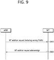
- FIG. 9 shows a method of transmitting a serving PLMN ID by an eNB by using a WT additional preparation procedure according to an embodiment of the present invention.
- the eNB may transmit a serving public land mobile network identity (PLMN ID) to the WT.
- the serving PLMN ID may be transmitted through a WT additional preparation procedure.
- the serving PLMN ID may be included in a WT Addition Request message.
- the WT may include at least one WLAN AP.
- the WT Addition Request message may be defined by Table 1. [Table 1] IE/Group Name Presence Semantics description Criticality Assigned Criticality Message Type M YES reject eNB UE XwAP ID M Assigned by the eNB YES reject UE Identity M YES reject WLAN Security Information O YES reject Serving PLMN O The serving PLMN for the UE.
- the WT Addition Request message may include a serving PLMN.
- the serving PLMN may be a serving PLMN for a UE.
- the serving PLMN and the serving PLMN ID may be used in the same concept.
- the WT Addition Request message may be a UE-specific message. That is, the WT Addition Request message may be transmitted in a UE specific manner for a specific UE.
- the serving PLMN ID may be one PLMN ID selected from at least one PLMN ID.
- the eNB may receive the at least one PLMN ID from the WT.
- the at least one PLMN ID may be received from the WT through an Xw setup procedure.
- the at least one PLMN ID may be included in an Xw Setup Response message.
- the Xw Setup Response message may be defined by Table 2. [Table 2] IE/Group Name Presence Semantics description Criticality Assigned Criticality Message Type M YES reject WT ID M YES reject WLAN Identifier List List of identifiers supported by the WT YES reject >WLAN Identifier Item >>WLAN Information M Criticality Diagnostics O YES ignore
- the Xw Setup Response message may include a WT ID.
- the WT ID may be an IE used to distinguish the WT.
- the WT ID may be defined by Table 3. [Table 3] IE/Group Name Presence Semantics description CHOICE WT ID Type M >WT ID Type 1 >>PLMN ID M >>Short WT ID M >WT ID Type 2
- the WT ID may include a PLMN ID. That is, the PLMN ID may be transmitted to the eNB by being included in the Xw Setup Response message.
- the WT may use the received serving PLMN ID for the purpose of managing a radio resource. That is, if the WT Addition Request message includes the serving PLMN ID, the WT may consider the serving PLMN ID in resource allocation for LWA. In addition, in step S920, the WT may transmit a WT Addition Request Acknowledge message to the eNB.
- the serving PLMN ID may be used for the purpose of managing the radio resource as follows.
- the WT may receive the serving PLMN ID, and may compare the received serving PLMN ID with a PLMN ID of a specific WLAN AP included in the WT. If the received serving PLMN ID coincides with the PLMN ID of the specific WLAN AP, the WT may preferentially allocate the radio resource to a UE corresponding to the serving PLMN ID through the specific WLAN AP. Alternatively, the WT may allow the UE corresponding to the serving PLMN ID to have a right to preferentially access the specific WLAN AP. Therefore, in the RAN sharing environment in which a plurality of WLAN APs are shared between operators, the operator may allocate a radio resource preferentially to a customer of the operator according to a policy, or may assign a preferential access right.
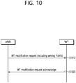
- FIG. 10 shows a method in which an eNB transmits a serving PLMN ID by using a WT modification preparation according to an embodiment of the present invention.
- the eNB may transmit the serving PLMN ID to a WT.
- the serving PLMN ID may be transmitted through the WT modification preparation procedure.
- the serving PLMN ID may be included in a WT Modification Request message.
- the WT may include at least one WLAN AP.
- the WT Modification Request message may be defined by Table 4. [Table 4] IE/Group Name Presence Semantics description Criticality Assigned Criticality Message Type M YES reject eNB UE XwAP ID M Assigned by the eNB YES reject WT UE XwAP ID M Assigned by the WT YES reject Cause M YES ignore Serving PLMN O The serving PLMN for the UE.
- the WT Modification Request message may include a serving PLMN.
- the serving PLMN may be a serving PLMN for a UE.
- the serving PLMN and the serving PLMN ID may be used in the same concept.
- the WT Modification Request message may be a UE-specific message. That is, the WT Modification Request message may be transmitted in a UE specific manner for a specific UE.
- the serving PLMN ID may be one PLMN ID selected from at least one PLMN ID.
- the eNB may receive the at least one PLMN ID from the WT.
- the at least one PLMN ID may be received from the WT through an Xw setup procedure.
- the at least one PLMN ID may be included in an Xw Setup Response message.
- the Xw Setup Response message may be defined by Table 2 above. Referring to Table 2 above, the Xw Setup Response message may include a WT ID.
- the WT ID may be an IE used to distinguish the WT.
- the WT ID may be defined by Table 3 above. Referring to Table 3 above, the WT ID may include a PLMN ID. That is, the PLMN ID may be transmitted to the eNB by being included in the Xw Setup Response message.
- the WT may use the received serving PLMN ID for the purpose of managing a radio resource. That is, if the WT Modification Request message includes the serving PLMN ID, the WT may consider the serving PLMN ID in resource allocation for LWA.
- the WT may transmit a WT Modification Request Acknowledge message to the eNB. If at least any one of modification requests based on the WT Modification Request message is allowed, the WT Modification Request Acknowledge message may be transmitted to the eNB.
- the operator may allocate a radio resource preferentially to a customer of the operator according to a policy, or may assign a preferential access right.
- FIG. 11 shows an example of allocating a radio resource based on a serving PLMN ID in an RAN sharing environment according to an embodiment of the present invention.
- an eNB may be an eNB shared by a first operator and a second operator.
- a WT may be a WT shared by the first operator and the second operator. That is, the WT may include a WLAN AP of the first operator and a WLAN AP of the second operator. It is assumed that a first WLAN AP, a third WLAN AP, and a fourth WLAN AP are WLAN APs of the first operator. It is assumed that a second WLAN AP and a fifth WLAN AP are WLAN APs of the second operator. It is assumed that a first UE is a UE served by the first operator, and the second UE is a UE served by the second operator. It is assumed that the first UE and the second UE are UEs capable of performing an LWA operation.
- the second operator may be configured such that the second UE can preferentially have access to the second WLAN AP and the fifth WLAN AP in comparison with the first UE.
- the second operator may be configured such that the second UE can preferentially allocate a radio resource through the second WLAN AP and the fifth WLAN AP in comparison with the first UE.
- FIG. 12 is a block diagram showing a method in which an eNB supports RAN sharing according to an embodiment of the present invention.
- the eNB transmits a WT Addition Request message to a WLAN termination (WT).
- the WT Addition Request message may include a serving public land mobile network identity (PLMN ID).
- the eNB may receive at least one PLMN ID from the WT.
- the at least one PLMN ID may be included in an Xw Setup Response message.
- the serving PLMN ID may be one PLMN ID selected from the at least one PLMN ID.
- the serving PLMN ID may be used by the WT to manage a radio resource of the WT. If the WT Addition Request message includes the serving PLMN ID, the serving PLMN ID may be used by the WT to allocate a resource for LTE-WLAN aggregation (LWA).
- LWA LTE-WLAN aggregation
- the eNB may receive a WT Addition Request Acknowledge message from the WT in response to the WT Addition Request message.
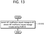
- FIG. 13 is a block diagram showing a method in which an eNB supports RAN sharing according to an embodiment of the present invention.
- the eNB transmits a WT Modification Request message to a WLAN termination (WT).
- the WT Modification Request message may include a serving public land mobile network identity (PLMN ID).
- the eNB may receive at least one PLMN ID from the WT.
- the at least one PLMN ID may be included in an Xw Setup Response message.
- the serving PLMN ID may be one PLMN ID selected from the at least one PLMN ID.
- the serving PLMN ID may be used by the WT to manage a radio resource of the WT. If the WT Modification Request message includes the serving PLMN ID, the serving PLMN ID may be used by the WT to allocate a resource for LTE-WLAN aggregation (LWA).
- LWA LTE-WLAN aggregation
- the eNB may receive a WT Modification Request Acknowledge message from the WT in response to the WT Modification Request message.
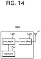
- FIG. 14 is a block diagram illustrating a wireless communication system according to the embodiment of the present invention.
- a BS 1400 includes a processor 1401, a memory 1402 and a transceiver 1403.
- the memory 1402 is connected to the processor 1401, and stores various information for driving the processor 1401.
- the transceiver 1403 is connected to the processor 1401, and transmits and/or receives radio signals.
- the processor 1401 implements proposed functions, processes and/or methods. In the above embodiment, an operation of the base station may be implemented by the processor 1401.
- the processor may include an application-specific integrated circuit (ASIC), a separate chipset, a logic circuit, and/or a data processing unit.
- the memory may include a read-only memory (ROM), a random access memory (RAM), a flash memory, a memory card, a storage medium, and/or other equivalent storage devices.
- the transceiver may include a base-band circuit for processing a wireless signal.
- the aforementioned methods can be implemented with a module (i.e., process, function, etc.) for performing the aforementioned functions.
- the module may be stored in the memory and may be performed by the processor.
- the memory may be located inside or outside the processor, and may be coupled to the processor by using various well-known means.
Landscapes
- Engineering & Computer Science (AREA)
- Computer Networks & Wireless Communication (AREA)
- Signal Processing (AREA)
- Computer Security & Cryptography (AREA)
- Mobile Radio Communication Systems (AREA)
Applications Claiming Priority (2)
| Application Number | Priority Date | Filing Date | Title |
|---|---|---|---|
| US201562222162P | 2015-09-22 | 2015-09-22 | |
| PCT/KR2016/010150 WO2017052121A1 (fr) | 2015-09-22 | 2016-09-09 | Procédé et dispositif permettant à une station de base de prendre en charge le partage de réseau ran |
Publications (2)
| Publication Number | Publication Date |
|---|---|
| EP3355651A1 true EP3355651A1 (fr) | 2018-08-01 |
| EP3355651A4 EP3355651A4 (fr) | 2019-03-13 |
Family
ID=58386246
Family Applications (1)
| Application Number | Title | Priority Date | Filing Date |
|---|---|---|---|
| EP16848847.6A Withdrawn EP3355651A4 (fr) | 2015-09-22 | 2016-09-09 | Procédé et dispositif permettant à une station de base de prendre en charge le partage de réseau ran |
Country Status (4)
| Country | Link |
|---|---|
| US (1) | US20180288815A1 (fr) |
| EP (1) | EP3355651A4 (fr) |
| CN (1) | CN108141898A (fr) |
| WO (1) | WO2017052121A1 (fr) |
Families Citing this family (4)
| Publication number | Priority date | Publication date | Assignee | Title |
|---|---|---|---|---|
| GB2544111A (en) * | 2015-11-06 | 2017-05-10 | Nec Corp | Communication system |
| EP3422769B1 (fr) * | 2016-04-01 | 2020-03-04 | Kyocera Corporation | Procédé de communication, processeur, station de base et dispositif de réseau |
| CN109874161B (zh) * | 2017-12-04 | 2021-08-31 | 成都鼎桥通信技术有限公司 | 提高业务转向wlan成功率的方法及系统 |
| WO2019241235A1 (fr) | 2018-06-11 | 2019-12-19 | Ofinno, Llc | Configuration de partage de réseau d'une station de base |
Family Cites Families (5)
| Publication number | Priority date | Publication date | Assignee | Title |
|---|---|---|---|---|
| CN102780990A (zh) * | 2011-05-11 | 2012-11-14 | 中兴通讯股份有限公司 | 一种网络共享下移动性参数修改的方法和系统 |
| WO2013063429A2 (fr) * | 2011-10-28 | 2013-05-02 | Research In Motion Limited | Procédés et appareil de gestion de supports pendant une opération de repli sur commutation de circuits |
| CN103327481B (zh) * | 2012-03-21 | 2018-08-17 | 中兴通讯股份有限公司 | 建立数据连接的方法、装置以及系统 |
| EP2978250B1 (fr) * | 2012-08-24 | 2017-05-10 | Huawei Device Co., Ltd. | Procédé, dispositif associé et système de configuration de dispositif de réseau local sans fil |
| CN105144830B (zh) * | 2013-10-28 | 2019-07-05 | Lg电子株式会社 | 用于在异构网络中执行双重连接的方法和装置 |
-
2016
- 2016-09-09 WO PCT/KR2016/010150 patent/WO2017052121A1/fr not_active Ceased
- 2016-09-09 US US15/761,797 patent/US20180288815A1/en not_active Abandoned
- 2016-09-09 CN CN201680054802.8A patent/CN108141898A/zh active Pending
- 2016-09-09 EP EP16848847.6A patent/EP3355651A4/fr not_active Withdrawn
Also Published As
| Publication number | Publication date |
|---|---|
| CN108141898A (zh) | 2018-06-08 |
| EP3355651A4 (fr) | 2019-03-13 |
| US20180288815A1 (en) | 2018-10-04 |
| WO2017052121A1 (fr) | 2017-03-30 |
Similar Documents
| Publication | Publication Date | Title |
|---|---|---|
| US11638320B2 (en) | Method and apparatus for resuming RRC connection in CU-DU division scenario | |
| US10932254B2 (en) | Method and apparatus for performing offloading procedures for WLAN-LTE integration and interworking in wireless communication system | |
| US11109349B2 (en) | Method for transmitting a paging message and device supporting the same | |
| US10425926B2 (en) | Method and apparatus for requesting additional system information | |
| US11089571B2 (en) | Method for performing a RAN based paging and device supporting the same | |
| US10798624B2 (en) | Method and apparatus for transmitting data in CU-DU split scenario | |
| US9713142B2 (en) | Method and apparatus for managing data radio bearers for dual connectivity in wireless communication system | |
| CN104541539B (zh) | 无线通信系统中关于设备对设备连接的干扰的信息的方法和设备 | |
| US10412649B2 (en) | Method and apparatus for performing handover procedure in wireless communication system | |
| US10609759B2 (en) | Method and apparatus for handling duplicated E-RABS for dual connectivity in wireless communication system | |
| EP3355644B1 (fr) | Procédés et dispositifs au moyen duquel un service d'ordre prioritaire est transmis | |
| US10980080B2 (en) | Method for reporting RRC state of terminal and apparatus for supporting same | |
| US20160119809A1 (en) | Method and apparatus for transmitting cell load information in wireless communication system | |
| JP2017525275A (ja) | 無線通信システムにおける二重接続のためのアクセス制御またはメンバーシップ検証を行う方法及び装置 | |
| US20200120476A1 (en) | Method for performing rlau procedure and device supporting the same | |
| EP3355651A1 (fr) | Procédé et dispositif permettant à une station de base de prendre en charge le partage de réseau ran | |
| US20150358972A1 (en) | Method and apparatus for transmitting cell load information in wireless communication system | |
| US20170303155A1 (en) | Method and apparatus for providing measurement results in a wireless communication system | |
| JP6513834B2 (ja) | 無線通信システムにおけるlte−wlanの調整を向上させるための方法及び装置 | |
| US10560838B2 (en) | Method and apparatus for deleting UE information by single base station |
Legal Events
| Date | Code | Title | Description |
|---|---|---|---|
| STAA | Information on the status of an ep patent application or granted ep patent |
Free format text: STATUS: THE INTERNATIONAL PUBLICATION HAS BEEN MADE |
|
| PUAI | Public reference made under article 153(3) epc to a published international application that has entered the european phase |
Free format text: ORIGINAL CODE: 0009012 |
|
| STAA | Information on the status of an ep patent application or granted ep patent |
Free format text: STATUS: REQUEST FOR EXAMINATION WAS MADE |
|
| 17P | Request for examination filed |
Effective date: 20180418 |
|
| AK | Designated contracting states |
Kind code of ref document: A1 Designated state(s): AL AT BE BG CH CY CZ DE DK EE ES FI FR GB GR HR HU IE IS IT LI LT LU LV MC MK MT NL NO PL PT RO RS SE SI SK SM TR |
|
| AX | Request for extension of the european patent |
Extension state: BA ME |
|
| DAV | Request for validation of the european patent (deleted) | ||
| DAX | Request for extension of the european patent (deleted) | ||
| RIC1 | Information provided on ipc code assigned before grant |
Ipc: H04W 92/20 20090101ALI20170411BHEP Ipc: H04W 76/02 20090101AFI20170411BHEP Ipc: H04W 88/08 20090101ALI20170411BHEP |
|
| A4 | Supplementary search report drawn up and despatched |
Effective date: 20190211 |
|
| RIC1 | Information provided on ipc code assigned before grant |
Ipc: H04W 92/20 20090101ALN20190205BHEP Ipc: H04W 48/18 20090101AFI20190205BHEP |
|
| STAA | Information on the status of an ep patent application or granted ep patent |
Free format text: STATUS: EXAMINATION IS IN PROGRESS |
|
| 17Q | First examination report despatched |
Effective date: 20191021 |
|
| STAA | Information on the status of an ep patent application or granted ep patent |
Free format text: STATUS: THE APPLICATION IS DEEMED TO BE WITHDRAWN |
|
| 18D | Application deemed to be withdrawn |
Effective date: 20200303 |