EP3356148B1 - Têtes d'impression - Google Patents
Têtes d'impression Download PDFInfo
- Publication number
- EP3356148B1 EP3356148B1 EP16889607.4A EP16889607A EP3356148B1 EP 3356148 B1 EP3356148 B1 EP 3356148B1 EP 16889607 A EP16889607 A EP 16889607A EP 3356148 B1 EP3356148 B1 EP 3356148B1
- Authority
- EP
- European Patent Office
- Prior art keywords
- printing material
- pressure equalization
- housing
- print nozzle
- reservoir
- Prior art date
- Legal status (The legal status is an assumption and is not a legal conclusion. Google has not performed a legal analysis and makes no representation as to the accuracy of the status listed.)
- Not-in-force
Links
Images


Classifications
-
- B—PERFORMING OPERATIONS; TRANSPORTING
- B41—PRINTING; LINING MACHINES; TYPEWRITERS; STAMPS
- B41J—TYPEWRITERS; SELECTIVE PRINTING MECHANISMS, i.e. MECHANISMS PRINTING OTHERWISE THAN FROM A FORME; CORRECTION OF TYPOGRAPHICAL ERRORS
- B41J2/00—Typewriters or selective printing mechanisms characterised by the printing or marking process for which they are designed
- B41J2/005—Typewriters or selective printing mechanisms characterised by the printing or marking process for which they are designed characterised by bringing liquid or particles selectively into contact with a printing material
- B41J2/01—Ink jet
- B41J2/135—Nozzles
- B41J2/145—Arrangement thereof
- B41J2/155—Arrangement thereof for line printing
-
- B—PERFORMING OPERATIONS; TRANSPORTING
- B41—PRINTING; LINING MACHINES; TYPEWRITERS; STAMPS
- B41J—TYPEWRITERS; SELECTIVE PRINTING MECHANISMS, i.e. MECHANISMS PRINTING OTHERWISE THAN FROM A FORME; CORRECTION OF TYPOGRAPHICAL ERRORS
- B41J2/00—Typewriters or selective printing mechanisms characterised by the printing or marking process for which they are designed
- B41J2/005—Typewriters or selective printing mechanisms characterised by the printing or marking process for which they are designed characterised by bringing liquid or particles selectively into contact with a printing material
- B41J2/01—Ink jet
- B41J2/135—Nozzles
- B41J2/14—Structure thereof only for on-demand ink jet heads
-
- B—PERFORMING OPERATIONS; TRANSPORTING
- B41—PRINTING; LINING MACHINES; TYPEWRITERS; STAMPS
- B41J—TYPEWRITERS; SELECTIVE PRINTING MECHANISMS, i.e. MECHANISMS PRINTING OTHERWISE THAN FROM A FORME; CORRECTION OF TYPOGRAPHICAL ERRORS
- B41J2/00—Typewriters or selective printing mechanisms characterised by the printing or marking process for which they are designed
- B41J2/005—Typewriters or selective printing mechanisms characterised by the printing or marking process for which they are designed characterised by bringing liquid or particles selectively into contact with a printing material
- B41J2/01—Ink jet
- B41J2/17—Ink jet characterised by ink handling
- B41J2/175—Ink supply systems ; Circuit parts therefor
-
- B—PERFORMING OPERATIONS; TRANSPORTING
- B41—PRINTING; LINING MACHINES; TYPEWRITERS; STAMPS
- B41J—TYPEWRITERS; SELECTIVE PRINTING MECHANISMS, i.e. MECHANISMS PRINTING OTHERWISE THAN FROM A FORME; CORRECTION OF TYPOGRAPHICAL ERRORS
- B41J2/00—Typewriters or selective printing mechanisms characterised by the printing or marking process for which they are designed
- B41J2/005—Typewriters or selective printing mechanisms characterised by the printing or marking process for which they are designed characterised by bringing liquid or particles selectively into contact with a printing material
- B41J2/01—Ink jet
- B41J2/17—Ink jet characterised by ink handling
- B41J2/175—Ink supply systems ; Circuit parts therefor
- B41J2/17503—Ink cartridges
- B41J2/17513—Inner structure
-
- B—PERFORMING OPERATIONS; TRANSPORTING
- B41—PRINTING; LINING MACHINES; TYPEWRITERS; STAMPS
- B41J—TYPEWRITERS; SELECTIVE PRINTING MECHANISMS, i.e. MECHANISMS PRINTING OTHERWISE THAN FROM A FORME; CORRECTION OF TYPOGRAPHICAL ERRORS
- B41J2/00—Typewriters or selective printing mechanisms characterised by the printing or marking process for which they are designed
- B41J2/005—Typewriters or selective printing mechanisms characterised by the printing or marking process for which they are designed characterised by bringing liquid or particles selectively into contact with a printing material
- B41J2/01—Ink jet
- B41J2/17—Ink jet characterised by ink handling
- B41J2/175—Ink supply systems ; Circuit parts therefor
- B41J2/17566—Ink level or ink residue control
-
- B—PERFORMING OPERATIONS; TRANSPORTING
- B41—PRINTING; LINING MACHINES; TYPEWRITERS; STAMPS
- B41J—TYPEWRITERS; SELECTIVE PRINTING MECHANISMS, i.e. MECHANISMS PRINTING OTHERWISE THAN FROM A FORME; CORRECTION OF TYPOGRAPHICAL ERRORS
- B41J2/00—Typewriters or selective printing mechanisms characterised by the printing or marking process for which they are designed
- B41J2/005—Typewriters or selective printing mechanisms characterised by the printing or marking process for which they are designed characterised by bringing liquid or particles selectively into contact with a printing material
- B41J2/01—Ink jet
- B41J2/17—Ink jet characterised by ink handling
- B41J2/175—Ink supply systems ; Circuit parts therefor
- B41J2/17596—Ink pumps, ink valves
-
- B—PERFORMING OPERATIONS; TRANSPORTING
- B41—PRINTING; LINING MACHINES; TYPEWRITERS; STAMPS
- B41J—TYPEWRITERS; SELECTIVE PRINTING MECHANISMS, i.e. MECHANISMS PRINTING OTHERWISE THAN FROM A FORME; CORRECTION OF TYPOGRAPHICAL ERRORS
- B41J2/00—Typewriters or selective printing mechanisms characterised by the printing or marking process for which they are designed
- B41J2/005—Typewriters or selective printing mechanisms characterised by the printing or marking process for which they are designed characterised by bringing liquid or particles selectively into contact with a printing material
- B41J2/01—Ink jet
- B41J2/135—Nozzles
- B41J2/14—Structure thereof only for on-demand ink jet heads
- B41J2002/14419—Manifold
-
- B—PERFORMING OPERATIONS; TRANSPORTING
- B41—PRINTING; LINING MACHINES; TYPEWRITERS; STAMPS
- B41J—TYPEWRITERS; SELECTIVE PRINTING MECHANISMS, i.e. MECHANISMS PRINTING OTHERWISE THAN FROM A FORME; CORRECTION OF TYPOGRAPHICAL ERRORS
- B41J2202/00—Embodiments of or processes related to ink-jet or thermal heads
- B41J2202/01—Embodiments of or processes related to ink-jet heads
- B41J2202/07—Embodiments of or processes related to ink-jet heads dealing with air bubbles
Definitions
- Printing devices include systems and devices for applying printing material to media.
- some printing devices such as inkjet printers, use print engines that spray or jet ink or other printing material onto print media.
- Such print engines often referred to as inkjets, use thermal or piezoelectric mechanisms to generate carefully timed and spaced droplets of ink to create a printed image.
- Inkjet printhead dies can be manufactured using various types of mechanical or semiconductor manufacturing and processing techniques. Individual printhead dies can be combined to create larger or wider inkjet printheads, sometimes referred to as page wide arrays.
- US2009/109268A1 discloses a printhead in which bubblers are provided between nozzles.
- US5363130A discloses an orientation sensitive valve operable with a bubble generator that provides a restricted flow of air bubbles into a reservoir of an ink-jet pen to relieve excessive back pressure in the pen.
- US2005/007427A1 discloses a print cartridge temperature control apparatus in which ink passes from a first chamber, across a printhead, and to a second chamber to control the temperature of the printhead.
- Inkjet printheads can include various mechanisms for applying ink to a media.
- a printhead can include a jet or sprayer nozzle array formed as an individual inkjet die in a mechanical or semiconductor manufacturing process.
- the terms "inkjet die” or “die” are used herein interchangeably to refer to any type of thermal or piezoelectric array of nozzles from which ink, or other printing material, can be ejected in a coordinated manner to generate a printed image.
- the nozzles in a particular die can be supplied with an ink or printing material from a corresponding reservoir.
- ink and “printing material” are used interchangeably to refer to any material that can be ejected from a nozzle or an inkjet die to form or finish a printed image.
- various colors of ink may ejected by a set of nozzles to generate a printed color image, while a topcoat or curing agent can be ejected by another set of nozzles to cure, protect, or otherwise finish the printed image.
- implementations of the present disclosure include pressure equalization elements that allow air into the printing material reservoir.
- the pressure equalization elements can include pressure sensitive valves or surface tension type bubblers (e.g., specifically dimensioned holes) that allow air to enter the printing material reservoir when the back pressure reaches a particular threshold level.
- a print nozzle array and a pressure equalization element can be disposed in a common side of a housing that includes a printing material reservoir.
- the nozzles of the die array can be coupled to the printing material reservoir through one duct or channel, while the pressure equalization element can be coupled to the printing material reservoir through another duct or channel. Accordingly, as air is drawn into the pressure equalization element and through the corresponding duct or channel, the flow of printing material to the nozzles can remain uninterrupted.
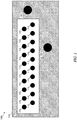
- FlG. 1 depicts a schematic of a side view 100 of a housing 105 that includes a print nozzle array 110 and pressure equalization elements 120.
- the aspect of the housing 105 shown can include an over-molded element formed around the print nozzle array 110 to extend the perimeter of the array 110.
- the housing and the over-molded element can include various moldable materials, such as plastic, composites, metal alloys, and the like.
- pressure equalization elements 120 can be formed in the over-molded element or the housing.
- the housing and the over-molded element can be a single integrated body.
- the print nozzle array 110 can include an inkjet die that includes an array of multiple print nozzles 115.
- the print nozzle array 110 can be formed in one process and then joined with the over-molded portion of the housing 105 in another process.
- the print nozzle array 110 can include various combinations of materials, such as metals, semiconductors, and plastics.
- the pressure equalization elements 120 can be disposed in the over-molded portion of the housing 105.
- Each of the print nozzles 115 and the pressure equalization elements 120 can be coupled to a printing material reservoir in the housing 105 by corresponding ducts or channels (not shown).
- the displacement of the pressure equalization elements 120 from the print nozzles 115 can be determined based on the location of the ducts or channels that feed the print nozzles 115 and/or the ducts or channels that couple the pressure equalization elements 120 to the printing material reservoir.
- FIG. 2 depicts side view 200 of an example housing 205 and corresponding cross-sectional views of an example housing 205 that includes a print nozzle array 110 having an array of print nozzles 115.
- the cross-sectional views are from the perspective of direction A to illustrate the functionality of example pressure equalization element 120 to allow air into the corresponding printing material reservoir 225 that equalizes the back pressure caused by the depletion of the printing material therein.
- the print nozzles 115 are coupled to the main printing material reservoir 225 by corresponding channel 215.
- the print nozzles 115 selectively eject drops of printing material, the level of the printing material in the reservoir 225 is depleted as it flows through the channel 215.
- an air can bubble can form in the channel 220 through the pressure equalization element 120. This process is illustrated in steps 1 through 4 in FIG. 2 .
- the pressure equalization element 120 can begin to allow air, or other gas, to form an initial air bubble 241 within the channel 220 that couples the pressure equalization element 120 to the printing material reservoir 225, as shown at step 1.
- the air bubble 243 expands to touch the side walls of channel 220.
- the bubble 245 increases in size in step 3, it further blocks the channel 220 and moves up into the printing material reservoir 225.
- step 4 when the bubble 247 has sufficient volume, buoyancy, or tension to overcome the friction with the walls of the channel 220, it moves into the printing material reservoir 225 to compensate the back pressure due to the depletion of the printing material.
- the placement of the pressure equalization element 120 in a position in the housing 205 at a particular distance from the print nozzles 115 can help prevent the occlusion of the channel 215 that could cut off the supply of printing material to the print nozzles 115.
- the printing material can be more fully utilized by allowing the remaining amount of printing material to flow through the channel 215 to the print nozzles 115 that might otherwise be prevented from flowing due to the back pressure.
- the channel 215, or other element of the housing 205 can include a printing material level sensor to determine when the printing material has been depleted past a threshold level. Because the pressure equalization element 120 is coupled to the printing material reservoir 225 by a separate channel 220, an air bubble formed in channel 220 to equalize the back pressure does not interfere with the functionality of the printing material level sensor.
- FIG. 3 depicts a view 201 of an example housing 305 according to an implementation of the present disclosure that includes multiple print nozzle arrays 110.
- multiple print nozzles arrays 110 can be aligned or staggered to form a page wide array printhead to print across the width of a page of print media in one pass without scanning the printhead.
- Each of the multiple print nozzle arrays can be included in an inkjet die coupled to corresponding separate printing material reservoirs by corresponding separate channels 215.
- each separate printing material reservoir is coupled to a corresponding pressure equalization element 120 by corresponding channel 220.
- the separate printing material reservoirs can store and dispense printing materials through the corresponding channels 215 and print nozzles 115.
- the separate printing material reservoirs are coupled to one another by additional pressure equalization or printing material distribution valves disposed between the reservoirs.
- FIG. 4 depicts a view 203 of the example housing 305 in which the printing material reservoirs 225 are shown as being connected a corresponding pressure equalization valve 315.
- printing material can flow from one printing material reservoir 225 to another printing material reservoir 225.
- Such implementations help ensure that one printing material reservoir coupled to a particular array of print nozzles 115 does not run dry before other printing material reservoirs 225 have been depleted.
- the lower pressure in the printing material reservoir 225-2 can cause the printing material to move in the direction indicated by the arrow 401.
- printing material can flow through the valve 315 from the printing material reservoir 225-1 to the printing material reservoir 225-2 once the difference in pressure between the two reservoirs is greater than a threshold difference.
- the pressure equalization mechanism of moving the printing material from one printing material reservoir 225 to another printing material reservoir 225 can augment or supplement the functionality of the pressure equalization elements 120.
- the pressure differential threshold of the valve 315 between printing material reservoirs 225 can be lower than, equal to, or greater than the threshold pressure differential required to activate the pressure equalization mechanism of the pressure equalization element 120.
- printing material can be distributed amongst the printing material reservoirs 225 before, during, or after air is allowed to enter through the pressure equalization element 120.
Landscapes
- Ink Jet (AREA)
Claims (7)
- Ensemble tête d'impression, comprenant :un boîtier (305) ayant un premier réservoir de matériau d'impression (225-1) et un second réservoir de matériau d'impression (225-2) ;des premier et second réseaux de buses d'impression (110) disposés dans un côté du boîtier (305) et accouplés à ceux respectifs des premier et second réservoirs de matériau d'impression (225-1, 225-2) au travers de premiers canaux respectifs (215) comportant le réseau de buses d'impression respectif (110) ; etun mécanisme d'égalisation de pression comprenant :des premier et second éléments d'égalisation de pression (120-1, 120-2) disposés sur le côté du boîtier (305) et accouplés à ceux respectifs des premier et second réservoirs de matériau d'impression (225-1, 225-2) à travers le second respectivement des canaux (220-1, 220-2) pour permettre à l'air d'entrer dans le réservoir de matériau d'impression respectif (225-1, 225-2) lorsqu'une pression dans ce réservoir de matériau d'impression (225-1, 225-2) change, et caractérisé en ce que le mécanisme d'égalisation de pression comprendune soupape d'égalisation de pression (315) accouplant les premier et second réservoirs de matériau d'impression (225-1, 225-2) pour égaliser les pressions à travers les premier et second réservoirs de matériau d'impression (225-1, 225-2) avant, pendant ou après que l'air puisse entrer par les éléments d'égalisation de pression.
- Ensemble tête d'impression selon la revendication 1, les premier et second réseaux de buses d'impression (110) étant disposés dans une première région du côté du boîtier (305) et les premier et second éléments d'égalisation de pression (120-1, 120-2) étant disposé dans une seconde région du côté du boîtier (305) déplacée de la première région d'une distance supérieure à une dimension des réseaux de buses d'impression (110) qui est suffisante pour empêcher l'occlusion du matériau d'impression entre les première et seconde régions.
- Ensemble tête d'impression selon la revendication 1 ou 2, comprenant en outre un capteur de niveau de matériau d'impression disposé dans chaque premier canal (215) pour détecter la présence ou l'absence d'un matériau d'impression dans le premier canal (215).
- Ensemble tête d'impression selon la revendication 3, les premier et second réseaux de buses d'impression (110) comprenant les capteurs de niveau de matériau d'impression.
- Ensemble tête d'impression selon l'une quelconque des revendications précédentes, chaque réseau de buses d'impression (110) comprenant un réseau de buses (115) disposées dans un matériau semi-conducteur, le boîtier (305) comprenant une matière plastique, et les premier et second éléments d'égalisation de pression (120-1, 120-2) comportent des ouvertures respectives dans la matière plastique.
- Ensemble tête d'impression selon l'une quelconque des revendications précédentes, chaque élément d'égalisation de pression (120-1, 120-2) comprenant un élément de barbotage passif.
- Ensemble tête d'impression selon l'une quelconque des revendications précédentes, comprenant en outre :
un élément surmoulé accouplé aux premier et second réseaux de buses d'impression (110) pour étendre le périmètre des réseaux de buses d'impression (110) et comprenant les premier et second éléments d'égalisation de pression (120-1, 120-2).
Applications Claiming Priority (1)
| Application Number | Priority Date | Filing Date | Title |
|---|---|---|---|
| PCT/US2016/016683 WO2017135959A1 (fr) | 2016-02-05 | 2016-02-05 | Têtes d'impression |
Publications (3)
| Publication Number | Publication Date |
|---|---|
| EP3356148A1 EP3356148A1 (fr) | 2018-08-08 |
| EP3356148A4 EP3356148A4 (fr) | 2019-05-22 |
| EP3356148B1 true EP3356148B1 (fr) | 2020-11-04 |
Family
ID=59499811
Family Applications (1)
| Application Number | Title | Priority Date | Filing Date |
|---|---|---|---|
| EP16889607.4A Not-in-force EP3356148B1 (fr) | 2016-02-05 | 2016-02-05 | Têtes d'impression |
Country Status (5)
| Country | Link |
|---|---|
| US (1) | US10363745B2 (fr) |
| EP (1) | EP3356148B1 (fr) |
| CN (1) | CN108290415B (fr) |
| TW (1) | TW201728468A (fr) |
| WO (1) | WO2017135959A1 (fr) |
Family Cites Families (20)
| Publication number | Priority date | Publication date | Assignee | Title |
|---|---|---|---|---|
| US5363130A (en) * | 1991-08-29 | 1994-11-08 | Hewlett-Packard Company | Method of valving and orientation sensitive valve including a liquid for controlling flow of gas into a container |
| US6585359B1 (en) | 1997-06-04 | 2003-07-01 | Hewlett-Packard Development Company, L.P. | Ink container providing pressurized ink with ink level sensor |
| US6398344B1 (en) | 2000-06-30 | 2002-06-04 | Silverbrook Research Pty Ltd | Print head assembly for a modular commercial printer |
| JP2002103597A (ja) * | 2000-07-25 | 2002-04-09 | Sony Corp | プリンタ及びプリンタヘッド |
| US6984029B2 (en) * | 2003-07-11 | 2006-01-10 | Hewlett-Packard Development Company, Lp. | Print cartridge temperature control |
| US6902256B2 (en) | 2003-07-16 | 2005-06-07 | Lexmark International, Inc. | Ink jet printheads |
| JP4054742B2 (ja) * | 2003-09-29 | 2008-03-05 | キヤノン株式会社 | インク供給システムおよび記録装置 |
| US7210771B2 (en) | 2004-01-08 | 2007-05-01 | Eastman Kodak Company | Ink delivery system with print cartridge, container and reservoir apparatus and method |
| KR100657950B1 (ko) * | 2005-02-05 | 2006-12-14 | 삼성전자주식회사 | 잉크 공급 장치와 이를 구비한 잉크젯 프린트헤드 패키지 |
| US9452605B2 (en) * | 2007-10-25 | 2016-09-27 | Hewlett-Packard Development Company, L.P. | Bubbler |
| KR20060134410A (ko) * | 2005-06-22 | 2006-12-28 | 삼성전자주식회사 | 마이크로 히트파이프를 구비한 어레이 프린트헤드 |
| CN101287606B (zh) | 2006-03-03 | 2010-11-03 | 西尔弗布鲁克研究有限公司 | 脉冲阻尼射流结构 |
| WO2007098524A1 (fr) | 2006-03-03 | 2007-09-07 | Silverbrook Research Pty Ltd | Structure fluidique à amortissement d'impulsions |
| EP1923215A1 (fr) * | 2006-11-14 | 2008-05-21 | Nederlandse Organisatie voor toegepast-natuurwetenschappelijk Onderzoek TNO | Système d'impression à haute pression à flux constant |
| US20090027457A1 (en) * | 2007-07-25 | 2009-01-29 | Clark Garrett E | Fluid ejection device |
| US8919938B2 (en) * | 2007-12-20 | 2014-12-30 | Hewlett-Packard Development Company, L.P. | Droplet generator |
| WO2009102322A1 (fr) | 2008-02-12 | 2009-08-20 | Hewlett-Packard Development Company, L.P. | Détection de fin de vie de tête d'impression intégrée |
| US7878635B2 (en) | 2008-03-03 | 2011-02-01 | Silverbrook Research Pty Ltd | Method of minimizing nozzle drooling during printhead priming |
| WO2013002762A1 (fr) * | 2011-06-27 | 2013-01-03 | Hewlett-Packard Development Company, L.P. | Détecteur de niveau d'encre et procédés associés |
| US8668304B1 (en) | 2012-08-31 | 2014-03-11 | Eastman Kodak Company | Inkjet printing system |
-
2016
- 2016-02-05 EP EP16889607.4A patent/EP3356148B1/fr not_active Not-in-force
- 2016-02-05 WO PCT/US2016/016683 patent/WO2017135959A1/fr not_active Ceased
- 2016-02-05 CN CN201680064862.8A patent/CN108290415B/zh not_active Expired - Fee Related
- 2016-02-05 US US15/772,358 patent/US10363745B2/en not_active Expired - Fee Related
-
2017
- 2017-02-03 TW TW106103667A patent/TW201728468A/zh unknown
Non-Patent Citations (1)
| Title |
|---|
| None * |
Also Published As
| Publication number | Publication date |
|---|---|
| TW201728468A (zh) | 2017-08-16 |
| US20180311959A1 (en) | 2018-11-01 |
| WO2017135959A1 (fr) | 2017-08-10 |
| EP3356148A1 (fr) | 2018-08-08 |
| CN108290415A (zh) | 2018-07-17 |
| EP3356148A4 (fr) | 2019-05-22 |
| CN108290415B (zh) | 2020-03-20 |
| US10363745B2 (en) | 2019-07-30 |
Similar Documents
| Publication | Publication Date | Title |
|---|---|---|
| US7997709B2 (en) | Drop on demand print head with fluid stagnation point at nozzle opening | |
| US9694582B1 (en) | Single jet recirculation in an inkjet print head | |
| US8596756B2 (en) | Offset inlets for multicolor printheads | |
| US10259218B2 (en) | Ejection device for inkjet printers | |
| EP2794276B1 (fr) | Distributeur de fluide | |
| EP2043869B1 (fr) | Cartouche d'impression | |
| TWI568597B (zh) | 具墨水進給孔橋接器的流體噴出裝置 | |
| EP3369574B1 (fr) | Ensemble chariot pour une imprimante ayant des réservoirs indépendants | |
| KR20190024692A (ko) | 고 충진 밀도 잉크젯 프린트 헤드들 내에서의 재순환을 위한 유체 디자인 | |
| EP3536508B1 (fr) | Tête d'impression | |
| US20080122912A1 (en) | Printhead reservoir with filter external to jet fluid path | |
| EP3356148B1 (fr) | Têtes d'impression | |
| CN109963699B (zh) | 分配不同大小的流体的流体喷射装置 | |
| US10144217B2 (en) | Recording apparatus, recording method, and liquid ejection head for recording an image by ejecting liquid droplets toward a recording medium while moving the liquid ejection head and the recording medium relative to each other | |
| US20160375689A1 (en) | Printhead assembly with fluid interconnect cover | |
| US10016984B2 (en) | Replaceable integrated printhead cartridge | |
| US20180281405A1 (en) | Liquid droplet jetting head | |
| US10780699B2 (en) | Printhead with removable printhead cover | |
| US11970010B2 (en) | Printhead with circulation channel | |
| US20150151539A1 (en) | Single jet fluidic design for high packing density in inkjet print heads | |
| US11214065B2 (en) | Fluid ejection die interlocked with molded body | |
| US8622531B1 (en) | Ink tank having a single gasket | |
| JP2017030352A (ja) | バブルスクリーンを有する単一噴射 |
Legal Events
| Date | Code | Title | Description |
|---|---|---|---|
| STAA | Information on the status of an ep patent application or granted ep patent |
Free format text: STATUS: THE INTERNATIONAL PUBLICATION HAS BEEN MADE |
|
| PUAI | Public reference made under article 153(3) epc to a published international application that has entered the european phase |
Free format text: ORIGINAL CODE: 0009012 |
|
| STAA | Information on the status of an ep patent application or granted ep patent |
Free format text: STATUS: REQUEST FOR EXAMINATION WAS MADE |
|
| 17P | Request for examination filed |
Effective date: 20180503 |
|
| AK | Designated contracting states |
Kind code of ref document: A1 Designated state(s): AL AT BE BG CH CY CZ DE DK EE ES FI FR GB GR HR HU IE IS IT LI LT LU LV MC MK MT NL NO PL PT RO RS SE SI SK SM TR |
|
| AX | Request for extension of the european patent |
Extension state: BA ME |
|
| DAV | Request for validation of the european patent (deleted) | ||
| DAX | Request for extension of the european patent (deleted) | ||
| RAP1 | Party data changed (applicant data changed or rights of an application transferred) |
Owner name: HEWLETT-PACKARD DEVELOPMENT COMPANY, L.P. |
|
| A4 | Supplementary search report drawn up and despatched |
Effective date: 20190418 |
|
| RIC1 | Information provided on ipc code assigned before grant |
Ipc: B41J 2/135 20060101ALI20190412BHEP Ipc: B41J 2/175 20060101AFI20190412BHEP Ipc: B41J 2/155 20060101ALI20190412BHEP Ipc: B41J 2/14 20060101ALI20190412BHEP |
|
| GRAP | Despatch of communication of intention to grant a patent |
Free format text: ORIGINAL CODE: EPIDOSNIGR1 |
|
| STAA | Information on the status of an ep patent application or granted ep patent |
Free format text: STATUS: GRANT OF PATENT IS INTENDED |
|
| INTG | Intention to grant announced |
Effective date: 20200618 |
|
| GRAS | Grant fee paid |
Free format text: ORIGINAL CODE: EPIDOSNIGR3 |
|
| GRAA | (expected) grant |
Free format text: ORIGINAL CODE: 0009210 |
|
| STAA | Information on the status of an ep patent application or granted ep patent |
Free format text: STATUS: THE PATENT HAS BEEN GRANTED |
|
| AK | Designated contracting states |
Kind code of ref document: B1 Designated state(s): AL AT BE BG CH CY CZ DE DK EE ES FI FR GB GR HR HU IE IS IT LI LT LU LV MC MK MT NL NO PL PT RO RS SE SI SK SM TR |
|
| REG | Reference to a national code |
Ref country code: GB Ref legal event code: FG4D |
|
| REG | Reference to a national code |
Ref country code: CH Ref legal event code: EP |
|
| REG | Reference to a national code |
Ref country code: AT Ref legal event code: REF Ref document number: 1330315 Country of ref document: AT Kind code of ref document: T Effective date: 20201115 |
|
| REG | Reference to a national code |
Ref country code: IE Ref legal event code: FG4D |
|
| REG | Reference to a national code |
Ref country code: DE Ref legal event code: R096 Ref document number: 602016047483 Country of ref document: DE |
|
| REG | Reference to a national code |
Ref country code: NL Ref legal event code: MP Effective date: 20201104 |
|
| REG | Reference to a national code |
Ref country code: AT Ref legal event code: MK05 Ref document number: 1330315 Country of ref document: AT Kind code of ref document: T Effective date: 20201104 |
|
| PG25 | Lapsed in a contracting state [announced via postgrant information from national office to epo] |
Ref country code: NO Free format text: LAPSE BECAUSE OF FAILURE TO SUBMIT A TRANSLATION OF THE DESCRIPTION OR TO PAY THE FEE WITHIN THE PRESCRIBED TIME-LIMIT Effective date: 20210204 Ref country code: RS Free format text: LAPSE BECAUSE OF FAILURE TO SUBMIT A TRANSLATION OF THE DESCRIPTION OR TO PAY THE FEE WITHIN THE PRESCRIBED TIME-LIMIT Effective date: 20201104 Ref country code: PT Free format text: LAPSE BECAUSE OF FAILURE TO SUBMIT A TRANSLATION OF THE DESCRIPTION OR TO PAY THE FEE WITHIN THE PRESCRIBED TIME-LIMIT Effective date: 20210304 Ref country code: GR Free format text: LAPSE BECAUSE OF FAILURE TO SUBMIT A TRANSLATION OF THE DESCRIPTION OR TO PAY THE FEE WITHIN THE PRESCRIBED TIME-LIMIT Effective date: 20210205 Ref country code: FI Free format text: LAPSE BECAUSE OF FAILURE TO SUBMIT A TRANSLATION OF THE DESCRIPTION OR TO PAY THE FEE WITHIN THE PRESCRIBED TIME-LIMIT Effective date: 20201104 |
|
| PG25 | Lapsed in a contracting state [announced via postgrant information from national office to epo] |
Ref country code: ES Free format text: LAPSE BECAUSE OF FAILURE TO SUBMIT A TRANSLATION OF THE DESCRIPTION OR TO PAY THE FEE WITHIN THE PRESCRIBED TIME-LIMIT Effective date: 20201104 Ref country code: AT Free format text: LAPSE BECAUSE OF FAILURE TO SUBMIT A TRANSLATION OF THE DESCRIPTION OR TO PAY THE FEE WITHIN THE PRESCRIBED TIME-LIMIT Effective date: 20201104 Ref country code: BG Free format text: LAPSE BECAUSE OF FAILURE TO SUBMIT A TRANSLATION OF THE DESCRIPTION OR TO PAY THE FEE WITHIN THE PRESCRIBED TIME-LIMIT Effective date: 20210204 Ref country code: LV Free format text: LAPSE BECAUSE OF FAILURE TO SUBMIT A TRANSLATION OF THE DESCRIPTION OR TO PAY THE FEE WITHIN THE PRESCRIBED TIME-LIMIT Effective date: 20201104 Ref country code: PL Free format text: LAPSE BECAUSE OF FAILURE TO SUBMIT A TRANSLATION OF THE DESCRIPTION OR TO PAY THE FEE WITHIN THE PRESCRIBED TIME-LIMIT Effective date: 20201104 Ref country code: IS Free format text: LAPSE BECAUSE OF FAILURE TO SUBMIT A TRANSLATION OF THE DESCRIPTION OR TO PAY THE FEE WITHIN THE PRESCRIBED TIME-LIMIT Effective date: 20210304 Ref country code: SE Free format text: LAPSE BECAUSE OF FAILURE TO SUBMIT A TRANSLATION OF THE DESCRIPTION OR TO PAY THE FEE WITHIN THE PRESCRIBED TIME-LIMIT Effective date: 20201104 |
|
| REG | Reference to a national code |
Ref country code: LT Ref legal event code: MG9D |
|
| PG25 | Lapsed in a contracting state [announced via postgrant information from national office to epo] |
Ref country code: HR Free format text: LAPSE BECAUSE OF FAILURE TO SUBMIT A TRANSLATION OF THE DESCRIPTION OR TO PAY THE FEE WITHIN THE PRESCRIBED TIME-LIMIT Effective date: 20201104 |
|
| PG25 | Lapsed in a contracting state [announced via postgrant information from national office to epo] |
Ref country code: SM Free format text: LAPSE BECAUSE OF FAILURE TO SUBMIT A TRANSLATION OF THE DESCRIPTION OR TO PAY THE FEE WITHIN THE PRESCRIBED TIME-LIMIT Effective date: 20201104 Ref country code: LT Free format text: LAPSE BECAUSE OF FAILURE TO SUBMIT A TRANSLATION OF THE DESCRIPTION OR TO PAY THE FEE WITHIN THE PRESCRIBED TIME-LIMIT Effective date: 20201104 Ref country code: EE Free format text: LAPSE BECAUSE OF FAILURE TO SUBMIT A TRANSLATION OF THE DESCRIPTION OR TO PAY THE FEE WITHIN THE PRESCRIBED TIME-LIMIT Effective date: 20201104 Ref country code: CZ Free format text: LAPSE BECAUSE OF FAILURE TO SUBMIT A TRANSLATION OF THE DESCRIPTION OR TO PAY THE FEE WITHIN THE PRESCRIBED TIME-LIMIT Effective date: 20201104 Ref country code: RO Free format text: LAPSE BECAUSE OF FAILURE TO SUBMIT A TRANSLATION OF THE DESCRIPTION OR TO PAY THE FEE WITHIN THE PRESCRIBED TIME-LIMIT Effective date: 20201104 Ref country code: SK Free format text: LAPSE BECAUSE OF FAILURE TO SUBMIT A TRANSLATION OF THE DESCRIPTION OR TO PAY THE FEE WITHIN THE PRESCRIBED TIME-LIMIT Effective date: 20201104 |
|
| REG | Reference to a national code |
Ref country code: DE Ref legal event code: R097 Ref document number: 602016047483 Country of ref document: DE |
|
| PG25 | Lapsed in a contracting state [announced via postgrant information from national office to epo] |
Ref country code: DK Free format text: LAPSE BECAUSE OF FAILURE TO SUBMIT A TRANSLATION OF THE DESCRIPTION OR TO PAY THE FEE WITHIN THE PRESCRIBED TIME-LIMIT Effective date: 20201104 |
|
| PLBE | No opposition filed within time limit |
Free format text: ORIGINAL CODE: 0009261 |
|
| STAA | Information on the status of an ep patent application or granted ep patent |
Free format text: STATUS: NO OPPOSITION FILED WITHIN TIME LIMIT |
|
| PG25 | Lapsed in a contracting state [announced via postgrant information from national office to epo] |
Ref country code: MC Free format text: LAPSE BECAUSE OF FAILURE TO SUBMIT A TRANSLATION OF THE DESCRIPTION OR TO PAY THE FEE WITHIN THE PRESCRIBED TIME-LIMIT Effective date: 20201104 |
|
| 26N | No opposition filed |
Effective date: 20210805 |
|
| REG | Reference to a national code |
Ref country code: BE Ref legal event code: MM Effective date: 20210228 |
|
| PG25 | Lapsed in a contracting state [announced via postgrant information from national office to epo] |
Ref country code: LI Free format text: LAPSE BECAUSE OF NON-PAYMENT OF DUE FEES Effective date: 20210228 Ref country code: LU Free format text: LAPSE BECAUSE OF NON-PAYMENT OF DUE FEES Effective date: 20210205 Ref country code: IT Free format text: LAPSE BECAUSE OF FAILURE TO SUBMIT A TRANSLATION OF THE DESCRIPTION OR TO PAY THE FEE WITHIN THE PRESCRIBED TIME-LIMIT Effective date: 20201104 Ref country code: NL Free format text: LAPSE BECAUSE OF FAILURE TO SUBMIT A TRANSLATION OF THE DESCRIPTION OR TO PAY THE FEE WITHIN THE PRESCRIBED TIME-LIMIT Effective date: 20201104 Ref country code: AL Free format text: LAPSE BECAUSE OF FAILURE TO SUBMIT A TRANSLATION OF THE DESCRIPTION OR TO PAY THE FEE WITHIN THE PRESCRIBED TIME-LIMIT Effective date: 20201104 Ref country code: CH Free format text: LAPSE BECAUSE OF NON-PAYMENT OF DUE FEES Effective date: 20210228 |
|
| PG25 | Lapsed in a contracting state [announced via postgrant information from national office to epo] |
Ref country code: SI Free format text: LAPSE BECAUSE OF FAILURE TO SUBMIT A TRANSLATION OF THE DESCRIPTION OR TO PAY THE FEE WITHIN THE PRESCRIBED TIME-LIMIT Effective date: 20201104 |
|
| PG25 | Lapsed in a contracting state [announced via postgrant information from national office to epo] |
Ref country code: IE Free format text: LAPSE BECAUSE OF NON-PAYMENT OF DUE FEES Effective date: 20210205 |
|
| PGFP | Annual fee paid to national office [announced via postgrant information from national office to epo] |
Ref country code: GB Payment date: 20220119 Year of fee payment: 7 Ref country code: DE Payment date: 20220119 Year of fee payment: 7 |
|
| PG25 | Lapsed in a contracting state [announced via postgrant information from national office to epo] |
Ref country code: IS Free format text: LAPSE BECAUSE OF FAILURE TO SUBMIT A TRANSLATION OF THE DESCRIPTION OR TO PAY THE FEE WITHIN THE PRESCRIBED TIME-LIMIT Effective date: 20210304 |
|
| PGFP | Annual fee paid to national office [announced via postgrant information from national office to epo] |
Ref country code: FR Payment date: 20220120 Year of fee payment: 7 |
|
| PG25 | Lapsed in a contracting state [announced via postgrant information from national office to epo] |
Ref country code: BE Free format text: LAPSE BECAUSE OF NON-PAYMENT OF DUE FEES Effective date: 20210228 |
|
| PG25 | Lapsed in a contracting state [announced via postgrant information from national office to epo] |
Ref country code: CY Free format text: LAPSE BECAUSE OF FAILURE TO SUBMIT A TRANSLATION OF THE DESCRIPTION OR TO PAY THE FEE WITHIN THE PRESCRIBED TIME-LIMIT Effective date: 20201104 |
|
| PG25 | Lapsed in a contracting state [announced via postgrant information from national office to epo] |
Ref country code: HU Free format text: LAPSE BECAUSE OF FAILURE TO SUBMIT A TRANSLATION OF THE DESCRIPTION OR TO PAY THE FEE WITHIN THE PRESCRIBED TIME-LIMIT; INVALID AB INITIO Effective date: 20160205 |
|
| REG | Reference to a national code |
Ref country code: DE Ref legal event code: R119 Ref document number: 602016047483 Country of ref document: DE |
|
| GBPC | Gb: european patent ceased through non-payment of renewal fee |
Effective date: 20230205 |
|
| PG25 | Lapsed in a contracting state [announced via postgrant information from national office to epo] |
Ref country code: GB Free format text: LAPSE BECAUSE OF NON-PAYMENT OF DUE FEES Effective date: 20230205 |
|
| PG25 | Lapsed in a contracting state [announced via postgrant information from national office to epo] |
Ref country code: GB Free format text: LAPSE BECAUSE OF NON-PAYMENT OF DUE FEES Effective date: 20230205 Ref country code: FR Free format text: LAPSE BECAUSE OF NON-PAYMENT OF DUE FEES Effective date: 20230228 Ref country code: DE Free format text: LAPSE BECAUSE OF NON-PAYMENT OF DUE FEES Effective date: 20230901 |
|
| PG25 | Lapsed in a contracting state [announced via postgrant information from national office to epo] |
Ref country code: MK Free format text: LAPSE BECAUSE OF FAILURE TO SUBMIT A TRANSLATION OF THE DESCRIPTION OR TO PAY THE FEE WITHIN THE PRESCRIBED TIME-LIMIT Effective date: 20201104 |
|
| PG25 | Lapsed in a contracting state [announced via postgrant information from national office to epo] |
Ref country code: MT Free format text: LAPSE BECAUSE OF FAILURE TO SUBMIT A TRANSLATION OF THE DESCRIPTION OR TO PAY THE FEE WITHIN THE PRESCRIBED TIME-LIMIT Effective date: 20201104 |
|
| PG25 | Lapsed in a contracting state [announced via postgrant information from national office to epo] |
Ref country code: TR Free format text: LAPSE BECAUSE OF FAILURE TO SUBMIT A TRANSLATION OF THE DESCRIPTION OR TO PAY THE FEE WITHIN THE PRESCRIBED TIME-LIMIT Effective date: 20201104 |